

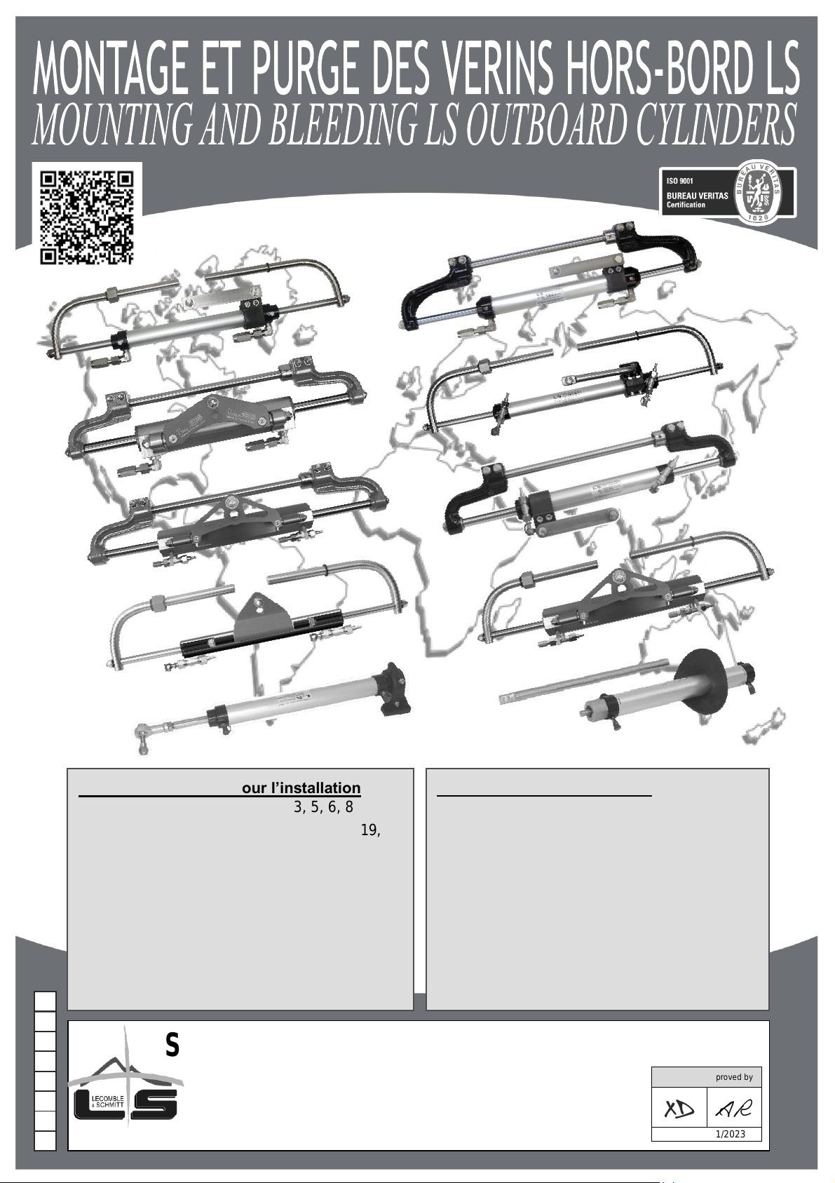
LECOMBLE & SCHMITT VHM 26 ST HB, VHM 28 ST HB, VHM 32 ST HB, VHM 28 ST HBR, VHM EX 80 HP User guide
...Page 1
Outillage nécessaire pour l’installation
- 1 jeu de clés mâles six pans : 3, 5, 6, 8
- 1 jeu de clés plates : 7, 8, 13, 14, 15, 17, 19, 27
- 1 jeu de tournevis plats
- 1 cutter
- 1 perceuse + 1 forêt 9
- 1 paire de tenaille
- 1 clé dynamométrique
- 1 tube de frein filet (type Loctite® n°222)
- huile de coupe entière (type Filduc 1879)
Tools required for the installation
- 1 set of hexagon keys: 3, 5, 6, 8
- 1 set of spanners: 7, 8, 13, 14, 15, 17, 19, 27
- 1 set of straight screwdrivers
- 1 cutter
- 1 drilling machine + 1 drill bit Ø 9
- 1 pair of pliers
- 1 torque wrench
- 1 tube of liquid nut-lock (type Loctite® n°222)
- neat cutting oil (type Filduc 1879)
M
0 1 2
-
T
O
N
S.A.S
LECOMBLE & SCHMITT
156 Route de Briscous - 64240 URT - FRANCE
T
+
33(0)559 562 646 -
v +
33(0)559 569 571
Validé par / Approved by
Date : 16/01/2023
Page 2
MONTAGE ET PURGE DES VERINS HORS-BORD LS
MOUNTING AND BLEEDING LS OUTBOARD CYLINDERS
SOMMAIRE Page
CONTENTS Page
Recommandations importantes ..................................................... 2
Instructions de montage des vérins
VHM 26 ST HB – VHM 28 ST HB – VHM 32 ST HB .......... 3
VHM 28 ST HBR.................................................................. 4
VHM EX 80 HP .................................................................... 5
VHM EX 125 HP .................................................................. 6
VHM EX 175 HP .................................................................. 7
VHM EX 225 HP .................................................................. 8
VHM 226 – VHM 228 ........................................................... 9
VHM 232 H ........................................................................ 10
VHM 232 COMPACT ......................................................... 11
VHM EX 350 HP – VHM EX 3500 HP ............................... 12
Types de raccordements ..................................................... 13 à 15
Montage et réorientation des raccords coudés orientables ......... 16
Remplissage et purge .......................................................... 17 à 20
Opérations de fin de purge ................................................ 20
Vérification du bon fonctionnement ............................................. 20
Déclaration de conformité de mécanismes de direction aux exigences
de la directive européenne 2013/53/UE du 20 Novembre 2013
Important Recommendations .................................................................... 2
Mounting Instructions for Cylinders
VHM 26 ST HB – VHM 28 ST HB – VHM 32 ST HB ............... 3
VHM 28 ST HBR .......................................................................... 4
VHM EX 80 HP ............................................................................ 5
VHM EX 125 HP .......................................................................... 6
VHM EX 175 HP .......................................................................... 7
VHM EX 225 HP .......................................................................... 8
VHM 226 – VHM 228 ................................................................... 9
VHM 232 H ................................................................................. 10
VHM 232 COMPACT ................................................................. 11
VHM EX 350 HP – VHM EX 3500 HP ..................................... 12
Types of Connection ...................................................................... 13 to 15
Mounting and reorienting swivel elbows ................................................ 16
Filling up and Bleeding ................................................................. 17 to 20
Procedure After Bleeding ............................................................ 20
Test Check Operation ............................................................................. 20
Declaration of conformity for steering mechanisms complying with the
requirements of European directive 2013/53/UE of 20 November 2013
Page 3
RECOMMANDATIONS IMPORTANTES
IMPORTANT RECOMMENDATIONS
! Toutes les cotes indiquées sont exprimées en millimètre
! All dimensions are quoted in mm
•Le vérin doit être installé par une personne ayant toutes les
compétences requises pour procéder au montage.
•Le vérin ne doit pas servir de marche pied.
•Le tube fileté du moteur
T devra être ajusté selon les schémas ci-
dessous et graissé avec un produit adapté.
•Pour les moteurs Hors-bord il est nécessaire de graisser
périodiquement l’intérieur du tube moteur, ainsi que les liaisons
bras/tige vérin et bras/arbre moteur. Sans graissage, les bras peuvent
s’oxyder dans le tube moteur et/ou sur leurs liaisons, ce qui pourrait
nuire au bon fonctionnement de la direction hydraulique.
•Pendant toute la durée d’installation, protéger le vérin et plus
particulièrement la tige contre tout risque de choc, de rayure ou de tout
autre type de dégradation.
•N’utiliser que la visserie d’origine fournie avec le vérin.
•Pour éviter tout grippage lors du vissage vis/écrou, nous préconisons
d’appliquer sur la vis de l’huile de coupe entière de type Filduc 1879.
•Par mesure de sécurité, nous recommandons de ne pas réutiliser les
écrous indesserrables (auto-freinés) après démontage.
•Il est impératif de respecter les couples de serrage indiqués
( … Nm)
pour chaque type de vérin.
•Aucune impureté ne doit pénétrer à l’intérieur du vérin. Les flexibles et
raccords doivent être nettoyés avant tout raccordement.
•Aucun élément étranger ne doit entraver le bon fonctionnement du
vérin (câblage électrique, tuyaux, objets rigides, etc.).
•Avant et après le raccordement de la tuyauterie, s’assurer que le
vérin reste libre dans tous ses déplacements :
- En déplaçant le moteur de butée à butée.
- En effectuant le relevage complet du moteur.
•Ne pas installer ce matériel dans une zone où la température excède
77°C.
• The cylinder should be installed by a qualified person.
•
Do not use the cylinder as a footboard.
•
The motor screw tube T must be adjusted as per the drawings below and
greased with a suitable product.
•
It
On outboard motors, it is necessary to grease the inside of the engine screw
tube and the connections bullhorn/cylinder rod and bullhorn/cylinder shaft
on a regular basis. If this is not done, the cylinder bullhorns may oxidize in
the engine screw tube and/or on their connections which could affect the
proper operation of the hydraulic steering system.
•
Protect the cylinder and more particularly the cylinder rod against risks of
impact, scratches and any other degradation during the installation procedure.
•
Use only original screws and bolts supplied with the cylinder.
• To prevent seizing while screwing in the screw/nut, we recommend that the
screw be greased with whole cutting oil (type Filduc 1879).
•
For safety reasons, we recommend not to reuse self locking nuts after
removal.
•
It is imperative to follow the indicated tightening torque ( … Nm) for each
cylinder type.
•
No impurities should enter the cylinder. Hydraulic hoses and fittings
should be cleaned prior to connection.
•
No foreign body should hinder the cylinder operation (electrical cabling,
tubing, rigid objects, etc.).
•
Before and after connecting the tubes, make sure that the cylinder can
move freely:
- by moving the motor from lock to lock.
- by fully tilting the motor.
• Do not install this equipment in an area where the temperature exceeds 77°C.
2
Page 4
Instructions de montage
Mounting instructions
Type de vérin
Type of Cylinder
VHM 26 ST HB
VHM 28 ST HB
VHM 32 ST HB
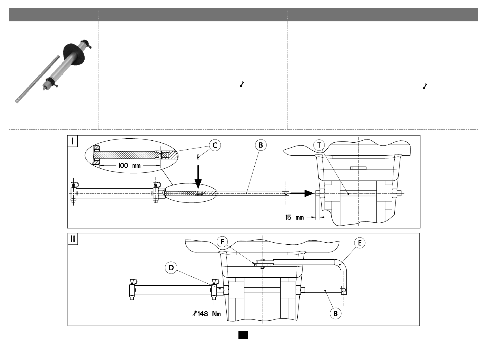
1. (Fig.I) Régler le tube fileté du moteur T à 15 mm.
2. (Fig.I) Faire sortir la tige du vérin de 100 mm puis accoupler la
rallonge B à la tige du vérin à l’aide de la goupille C.
3. (Fig.I) Graisser la rallonge B et l’emmancher totalement dans
le tube fileté T.
!Vérifier que la rallonge coulisse librement dans le tube fileté T.
4. (Fig.II) Visser l’écrou du vérin D et le bloquer ( 148 Nm),
purgeurs du vérin orientés vers le haut.
5. (Fig.II) Accoupler le bras de liaison E fourni avec le moteur à
l’extrémité de la rallonge du vérin B et au levier du moteur F
selon les préconisations du fabricant du moteur.
1. (Dwg I) Adjust the engine screw tube T at 15 mm.
2. (Dwg I) Pull out the cylinder rod by 100 mm and connect it to the
extension rod B with pin C.
3. (Dwg I) Grease extension rod B and fully insert it into the engine
screw tube T.
!Check that the extension rod can move freely inside the engine screw
tube T.
4. (Dwg II) Tighten the cylinder nut D and lock it ( 148 Nm) with the
cylinder bleeders upwards.
5. (Dwg II) Connect the linkage E supplied with the motor to the end
of the extension rod B and to the motor lever F as per the
recommendations of the motor manufacturer.
3
Page 5
Instructions de montage
Mounting instructions
Type de vérin
Type of Cylinder
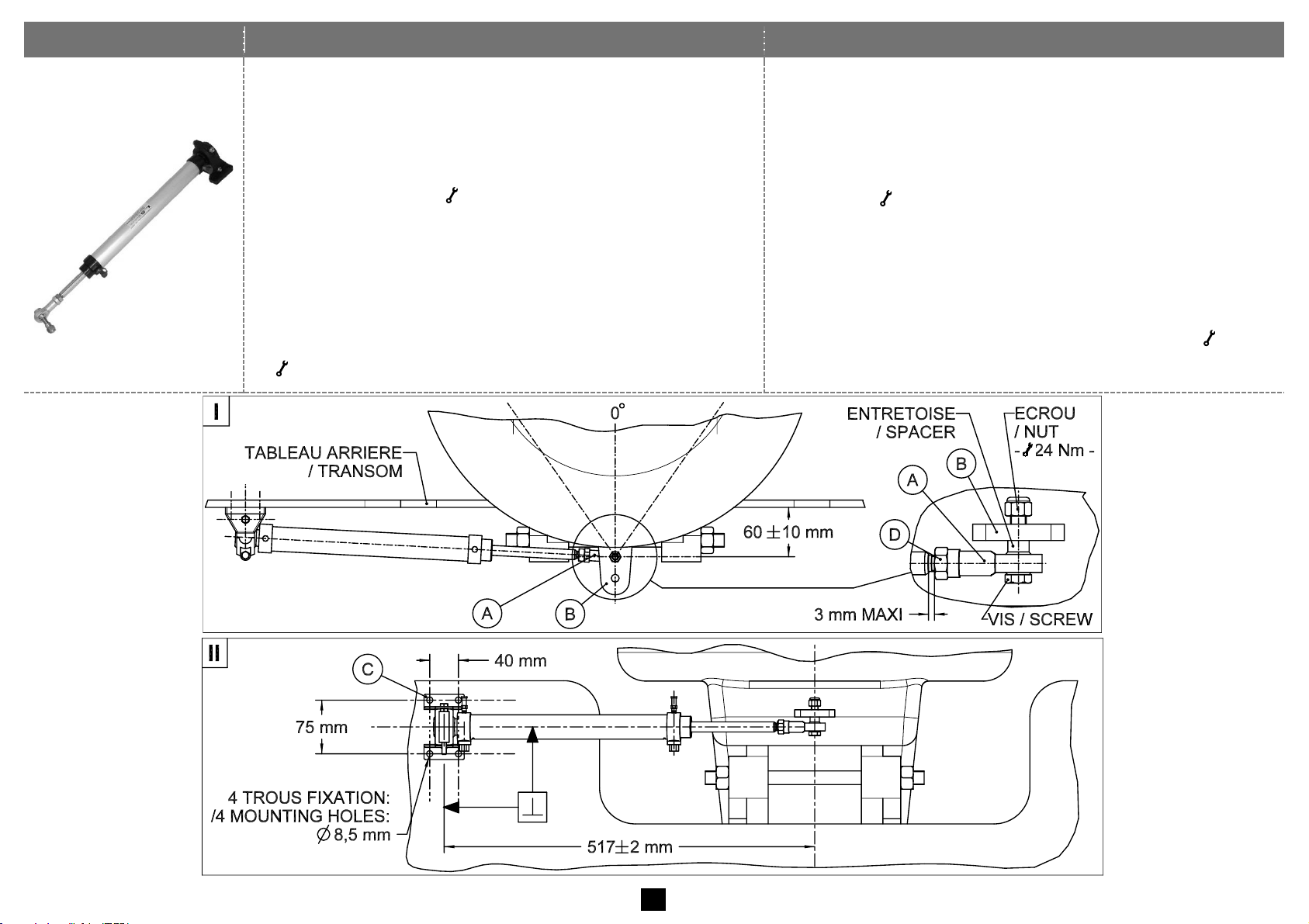
VHM 28 ST HBR
1. Mettre le moteur en position verticale et le positionner au centre
de sa course (idem navigation en ligne droite – Fig.I).
2. (Fig.I) Accoupler la chape à rotule A au levier du moteur B en
respectant :
- la cote de 60 10 mm
- l’empilage vis, entretoise et écrou
- le couple de serrage ( 24 Nm)
3. (Fig.II) Faire sortir la tige du vérin à mi-course de manière à
respecter la cote de 517 2 mm et fixer le palier C sur le
tableau arrière (à l’aide d’une visserie appropriée aux quatre
trous de fixation 8,5 mm) en ayant pris soin de le positionner
perpendiculairement à l’axe du vérin. ! Le palier C est livré
préréglé et ne doit pas être réajusté.
4. (Fig.I) Bloquer le contre-écrou D contre la chape à rotule A
( 15 Nm).
1. Position the motor vertically and in the middle of its travel (as when
navigating in a straight line – Dwg I).
2. (Dwg I) Connect the swivel yoke A to the motor lever B by
observing the following:
- the dimension of 60 10 mm
- the mounting order of screw, spacer and nut
- the torque ( 24 Nm)
3. (Dwg II) Pull out the cylinder rod at half-stroke to reach the
dimension of 517 2 mm and fix the bearing C on the transom (at
the four 8.5 mm mounting holes with appropriate screws and bolts).
Make sure the bearing is perpendicular to the cylinder axis. ! The
bearing C is pre-adjusted in factory and should not be readjusted.
4. (Dwg I) Lock the counternut D against the swivel yoke A ( 15 Nm).
4
Page 6
Instructions de montage
Mounting instructions
Type de vérin
Type of Cylinder
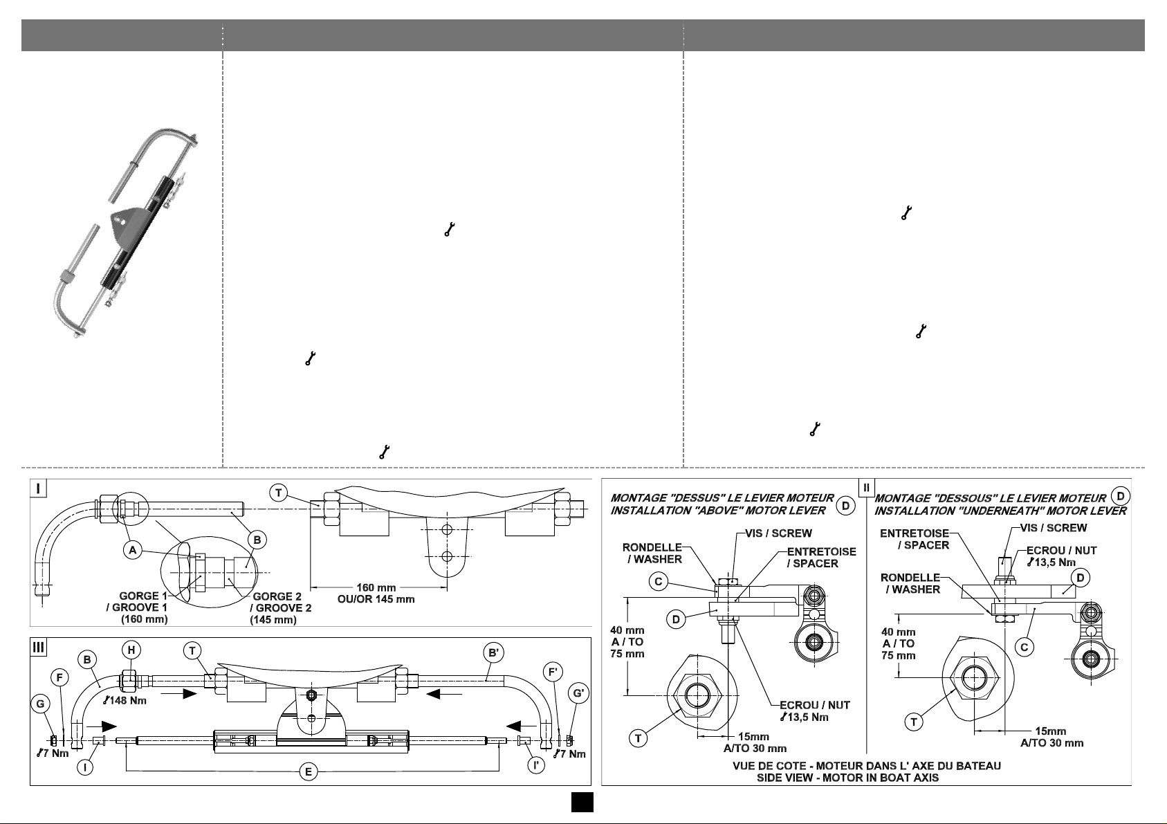
VHM EX 80 HP
1. (Fig.I) Régler le tube fileté du moteur T à 160 mm de l'axe du
moteur. Sur certains moteurs, cette cote est fixée à 145 mm ;
dans ce cas, déplacer la bague A de la gorge 1 vers la
gorge 2 sur le bras B du vérin.
2. (Fig.II) En fonction du montage "Dessus" ou "Dessous",
présenter le vérin sans ses bras de manière à fixer l'attache C
au levier du moteur D.
! Respecter les cotes 40 à 75 mm et 15 à 30 mm par rapport
à l'axe du tube fileté du moteur T ainsi que l'empilage vis,
rondelle, entretoise et écrou ( 13,5 Nm).
3. Raccorder les flexibles (voir page 13) puis purger la direction
(voir page 15).
4. (Fig.III) Accoupler le bras B à l'extrémité de la tige E avec la
rondelle F, l'écrou G et le fourreau I en l'emmanchant
simultanément dans le tube du moteur T. Visser l'écrou
tournant H associé à du frein filet (type Loctite® n°222) et le
bloquer ( 148 Nm).
Accoupler le bras b à l’autre extrémité de la tige E avec la
rondelle f, l'écrou g et le fourreau i en l'emmanchant
simultanément dans le tube fileté du moteur T.
5. (Fig.III) Terminer le montage du vérin en bloquant simultanément
les écrous G et g ( 7 Nm) à l'aide de 2 clés plates.
1. (Dwg I) Adjust the engine screw tube T at 160 mm from the motor
central axis. On some motors this dimension is 145 mm; in this case,
shift ring A from groove 1 to groove 2 on the cylinder bullhorn B.
2. (Dwg II) In function of the installation "above" or "underneath" the
motor lever, position the cylinder without its bullhorns to connect the
cylinder connection plate C to the motor lever D.
! Observe the dimensions 40 to 75 mm and 15 to 30 mm from the
engine screw tube axis T and the correct mounting order of the
screw, washer, spacer and nut ( 13.5 Nm).
3. Connect the flexible tubes (see page 13), then bleed the steering
system (see page 15).
4. (Dwg III) Connect the bullhorn B to the rod end E with washer F
,nut G and the adapter I by simultaneously inserting the bullhorn
into the engine screw tube T. Tighten the nut H and glue it (glue
type Loctite® n°222) then lock it ( 148 Nm).
Connect the bullhorn b to the other rod end E with washer f,nut
g and the adapter i by simultaneously inserting the bullhorn into
the engine screw tube T.
5. (Dwg III) Finalise the cylinder installation by simultaneously locking
nuts G and g ( 7 Nm) with 2 spanners.
5
Page 7
Instructions de montage
Mounting instructions
Type de vérin
Type of Cylinder
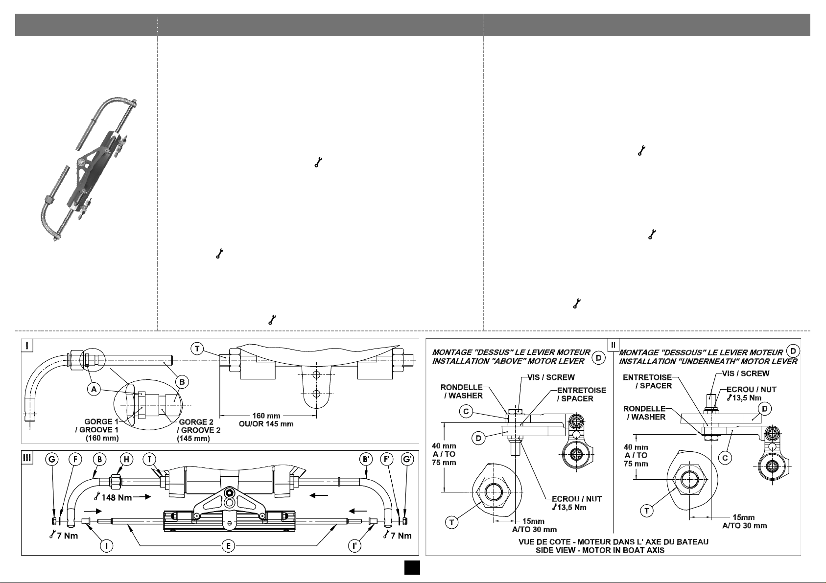
VHM EX 125 HP
1. (Fig.I) Régler le tube fileté du moteur T à 160 mm de l'axe du
moteur. Sur certains moteurs, cette cote est fixée à 145 mm ;
dans ce cas, déplacer la bague A de la gorge 1 vers la
gorge 2 sur le bras B du vérin.
2. (Fig.II) En fonction du montage "Dessus" ou "Dessous",
présenter le vérin sans ses bras de manière à fixer l'attache C
au levier du moteur D.
! Respecter les cotes 40 à 75 mm et 15 à 30 mm par rapport
à l'axe du tube fileté du moteur T ainsi que l'empilage vis,
rondelle, entretoise et écrou ( 13,5 Nm).
3. Raccorder les flexibles (voir page 13) puis purger la direction
(voir page 15).
4. (Fig.III) Accoupler le bras B à l'extrémité de la tige E avec la
rondelle F, l'écrou G et le fourreau I en l'emmanchant
simultanément dans le tube du moteur T. Visser l'écrou
tournant H associé à du frein filet (type Loctite® n°222) et le
bloquer ( 148 Nm).
Accoupler le bras b à l’autre extrémité de la tige E avec la
rondelle f, l'écrou g et le fourreau i en l'emmanchant
simultanément dans le tube fileté du moteur T.
5. (Fig.III) Terminer le montage du vérin en bloquant simultanément
les écrous G et g ( 7 Nm) à l'aide de 2 clés plates.
1. (Dwg I) Adjust the engine screw tube T at 160 mm from the motor
central axis. On some motors this dimension is 145 mm; in this case,
shift ring A from groove 1 to groove 2 on the cylinder bullhorn B.
2. (Dwg II) In function of the installation "above" or "underneath" the
motor lever, position the cylinder without its bullhorns to connect the
cylinder connection plate C to the motor lever D.
! Observe the dimensions 40 to 75 mm and 15 to 30 mm from the
engine screw tube axis T and the correct mounting order of the
screw, washer, spacer and nut ( 13.5 Nm).
3. Connect the flexible tubes (see page 13), then bleed the steering
system (see page 15).
4. (Dwg III) Connect the bullhorn B to the rod end E with washer F
,nut G and the adapter I by simultaneously inserting the bullhorn
into the engine screw tube T. Tighten the nut H and glue it (glue
type Loctite® n°222) then lock it ( 148 Nm).
Connect the bullhorn b to the other rod end E with washer f,nut
g and the adapter i by simultaneously inserting the bullhorn into
the engine screw tube T.
5. (Dwg III) Finalise the cylinder installation by simultaneously locking
nuts G and g ( 7 Nm) with 2 spanners.
6
Page 8
Instructions de montage
Mounting instructions
Type de vérin
Type of Cylinder
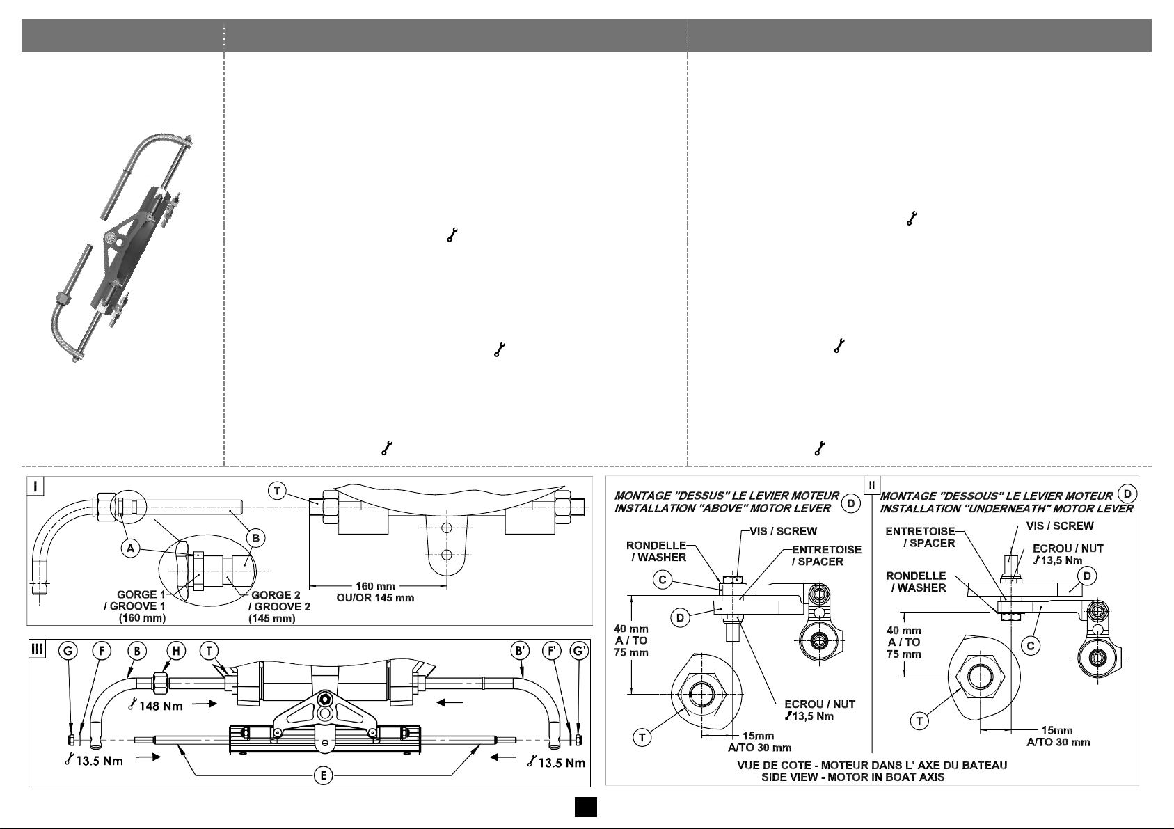
VHM EX 175 HP
1. (Fig.I) Régler le tube fileté du moteur T à 160 mm de l'axe du
moteur. Sur certains moteurs, cette cote est fixée à 145 mm ;
dans ce cas, déplacer la bague A de la gorge 1 vers la
gorge 2 sur le bras B du vérin.
2. (Fig.II) En fonction du montage "Dessus" ou "Dessous",
présenter le vérin sans ses bras de manière à fixer l'attache C
au levier du moteur D.
! Respecter les cotes 40 à 75 mm et 15 à 30 mm par rapport
à l'axe du tube fileté du moteur T ainsi que l'empilage vis,
rondelle, entretoise et écrou ( 13,5 Nm).
3. Raccorder les flexibles (voir page 13) puis purger la direction
(voir page 15).
4. (Fig.III) Accoupler le bras B à l'extrémité de la tige E avec la
rondelle F et l'écrou G en l'emmanchant simultanément dans le
tube du moteur T. Visser l'écrou tournant H associé à du frein
filet (type Loctite® n°222) et le bloquer ( 148 Nm).
Accoupler le bras b à l’autre extrémité de la tige E avec la
rondelle f et l'écrou g en l'emmanchant simultanément dans
le tube fileté du moteur T.
5. (Fig.III) Terminer le montage du vérin en bloquant simultanément
les écrous G et g ( 13,5 Nm) à l'aide de 2 clés plates.
1. (Dwg I) Adjust the engine screw tube T at 160 mm from the motor
central axis. On some motors this dimension is 145 mm; in this case,
shift ring A from groove 1 to groove 2 on the cylinder bullhorn B.
2. (Dwg II) In function of the installation "above" or "underneath" the
motor lever, position the cylinder without its bullhorns to connect the
cylinder connection plate C to the motor lever D.
! Observe the dimensions 40 to 75 mm and 15 to 30 mm from the
engine screw tube axis T and the correct mounting order of the
screw, washer, spacer and nut ( 13.5 Nm).
3. Connect the flexible tubes (see page 13), then bleed the steering
system (see page 15).
4. (Dwg III) Connect the bullhorn B to the rod end E with washer F
and nut G by simultaneously inserting the bullhorn into the engine
screw tube T. Tighten the nut H and glue it (glue type Loctite®
n°222) then lock it ( 148 Nm).
Connect the bullhorn b to the other rod end E with washer f and
nut g by simultaneously inserting the bullhorn into the engine screw
tube T.
5. (Dwg III) Finalise the cylinder installation by simultaneously locking
nuts G and g ( 13.5 Nm) with 2 spanners.
7
Page 9
Instructions de montage
Mounting instructions
Type de vérin
Type of Cylinder
VHM EX 225 HP
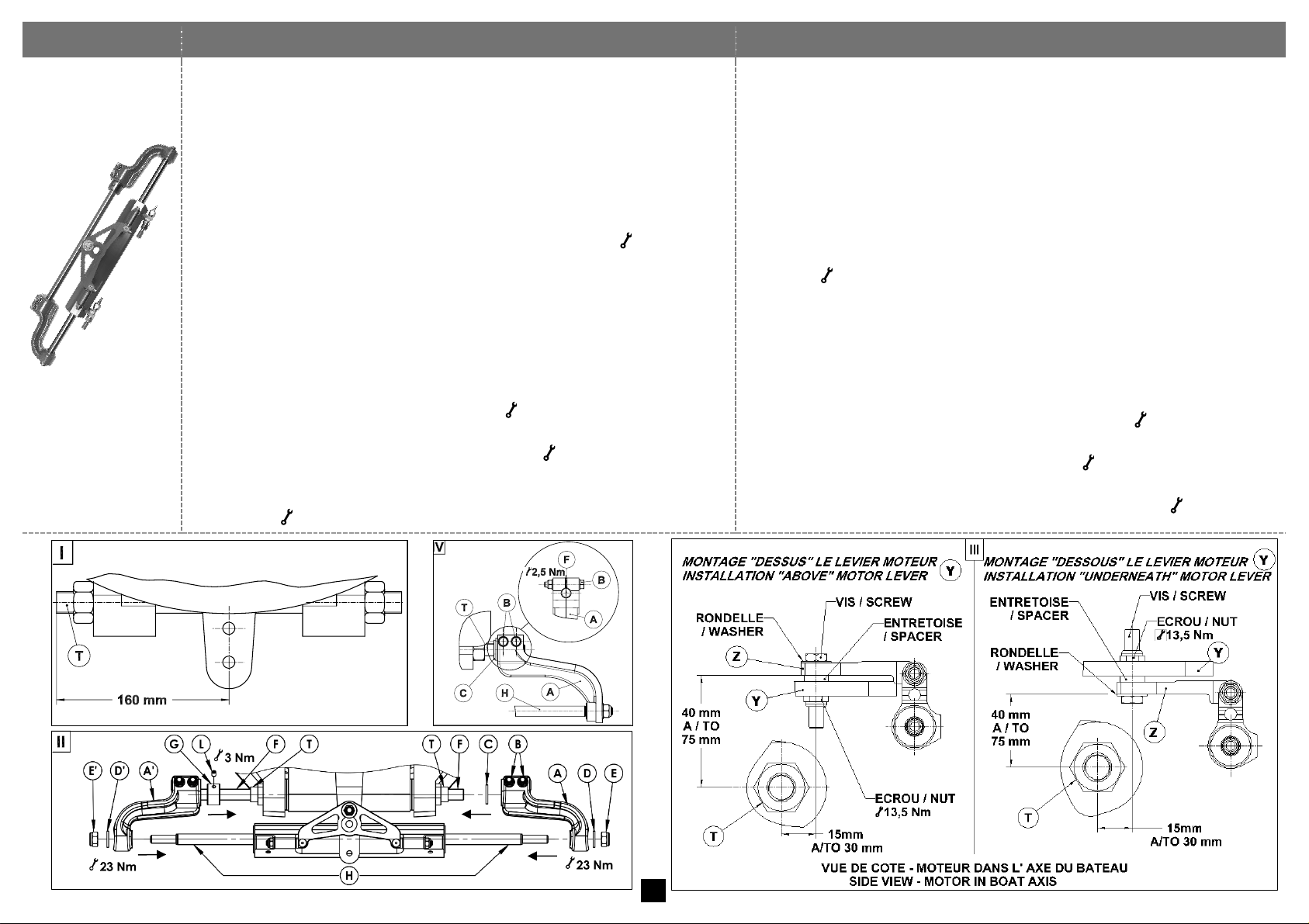
1. (Fig.I) Régler le tube fileté du moteur T à 160 mm de l'axe du moteur.
2. (Fig.II) Désaccoupler entièrement le bras A du vérin en desserrant les
vis B et en retirant les rondelles et écrous EDC. Retirer l’écrou e et
la rondelle d du bras a. Desserrer légèrement la vis L afin de retirer
l’écrou G de l’arbre F puis désaccoupler le bras a de la tige H.
3. (Fig.III) En fonction du montage "Dessus" ou "Dessous", présenter le vérin
sans ses bras afin de fixer l'attache Z au levier du moteur Y.
! Respecter les cotes 40 à 75 mm et 15 à 30 mm par rapport à l'axe du tube
fileté du moteur T ainsi que l'empilage vis, rondelle, et écrou ( 13,5 Nm).
4. Raccorder les flexibles (page 13) puis purger la direction (page 15).
5. (Fig.II) Visser entièrement l’écrou G sur le tube moteur T. Présenter
l’ensemble aF afin d’emmancher simultanément l’arbre F dans le
tube du moteur T et le bras a dans la tige H jusqu’à arriver en butée
sur l’écrou G. Remonter la rondelle d et l’écrou e.
Insérer la rondelle C dans l’arbre F. Emmancher simultanément le
bras A dans l’arbre F et la tige H. Remonter la rondelle D et l’écrou
E. Visser et bloquer les écrous E et e ( 23 Nm).
6. (Fig.IV et Fig.II) S'assurer que l'extrémité de l'arbre F arrive au ras de la
face extérieure du bras A et bloquer les vis B ( 2,5 Nm).
7. (Fig.II) Terminer le montage du vérin en dévissant l'écrou G pour l'amener
en butée contre le bras a de manière à supprimer le jeu latéral ; bloquer
la vis L ( 3 Nm).
1. (Dwg I) Adjust the engine screw tube T at 160 mm from the motor central axis.
2. (Dwg II) Remove the cylinder bullhorn A by undoing the screws Band
removing washers and nuts EDC. Remove nut e and its washer d from
the bullhorn a. Slightly loosen screw L in order to remove nut G from shaft
Fand then disconnect bullhorn a from rod H.
3. (Dwg III) In function of the installation "above" or "underneath" the motor
lever, position the cylinder without its bullhorns to connect the cylinder
connection plate Z to the motor lever Y.
! Observe the dimensions 40 to 75 mm and 15 to 30 mm from the engine
screw tube axis T and the correct mounting order of screw, washer, spacer
and nut ( 13.5 Nm).
4. Connect the flexible tubes (page 13) then bleed the steering system (page 15)
5. (Dwg II) Screw nut G completely on the motor screw tube T. Prepare and
position the assembly a F in order to insert simultaneously the shaft F into the
motor screw tube T and the bullhorn a on the cylinder rod H until it comes
against nut G.Put back washer d and nut e. Insert the washer C onto shaft
F. Insert simultaneously bullhorn A into shaft F and rod H. Reassemble the
washer D and nut E. Screw and tighten nuts E and e ( 23 Nm).
6. (Dwg IV and Dwg II) Make sure that the end part of shaft F is flush with the
exterior face of bullhorn A. Tighten screws B ( 2.5 Nm).
7. (Dwg II) Finalise the cylinder installation by undoing nut G and move it against
bullhorn a in order to eliminate lateral play. Tighten screw L ( 3 Nm).
8
Page 10
Instructions de montage
Mounting instructions
Type de vérin
Type of Cylinder
VHM 226
VHM 228
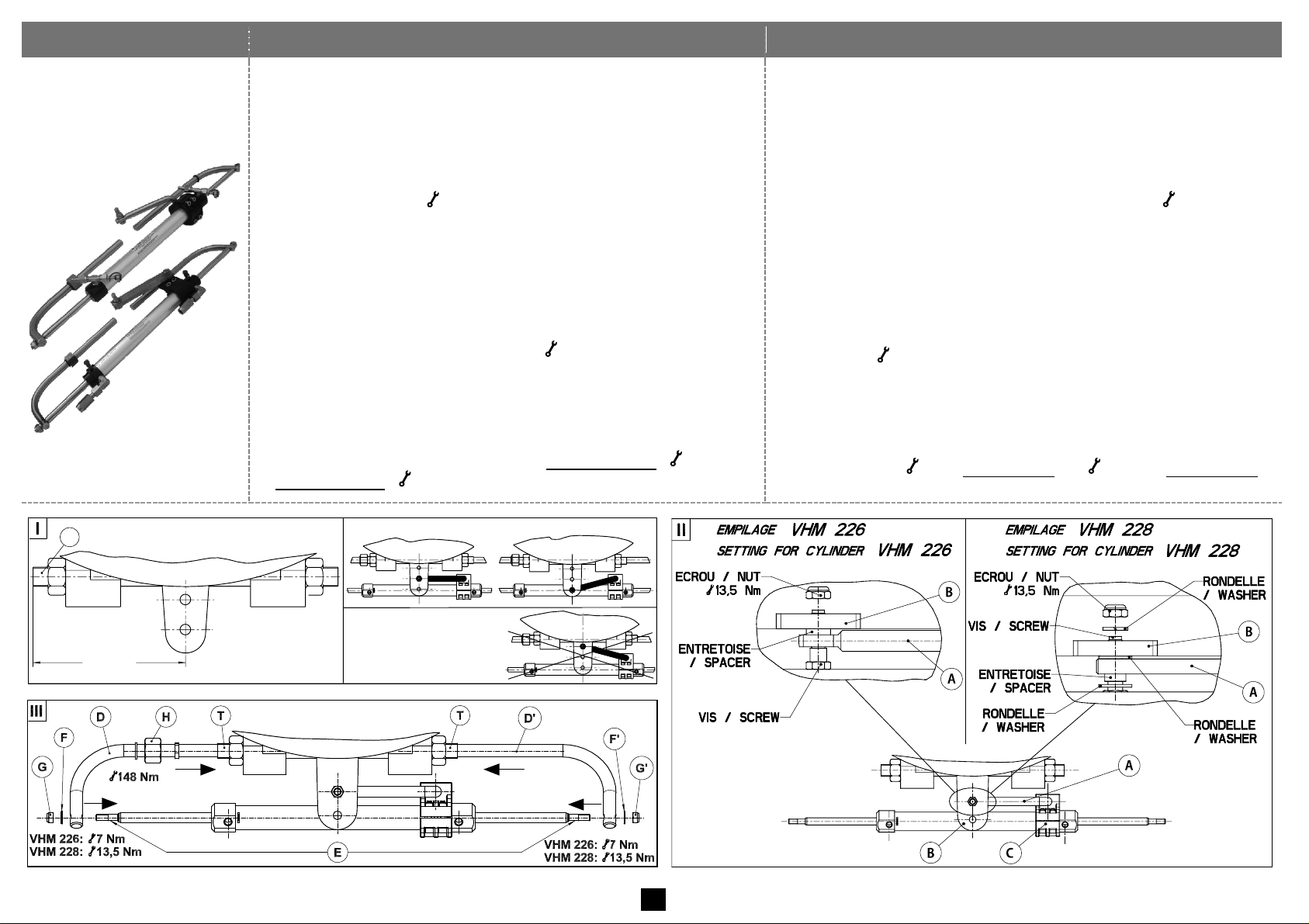
1. (Fig.I) Régler le tube fileté du moteur T à 160 mm de l'axe du
moteur.
2. (Fig.II) ! la bride C est préréglée et serrée en usine, son
réglage ne doit en aucun cas être modifié.
Présenter le vérin sans ses bras de manière à fixer l'attache A
au levier du moteur B en respectant l'empilage vis, rondelle,
entretoise et écrou ( 13,5 Nm).
3. Raccorder les flexibles (voir page 13) puis purger la direction
(voir page 15).
4. (Fig.III) Accoupler le bras D à l'extrémité de la tige E avec la
rondelle (VHM 226) F ou l'entretoise (VHM 228) F et l'écrou
G en l'emmanchant simultanément dans le tube fileté du
moteur T. Visser l'écrou tournant H associé à du frein filet
(type Loctite® n°222) et le bloquer ( 148 Nm).
Accoupler le bras d à l’autre extrémité de la tige E avec la
rondelle (VHM 226) f ou l'entretoise (VHM 228) f et l'écrou g
en l'emmanchant simultanément dans le tube fileté du moteur T.
5. (Fig.III) Terminer le montage du vérin en bloquant
simultanément les écrous G et g (pour VHM 226 : 7 Nm et
pour VHM 228 : 13,5 Nm) à l'aide de 2 clés plates.
1. (Dwg I) Adjust the engine screw tube T at 160 mm from the motor
axis.
2. Dwg II) ! The flange C is pre-adjusted and tightened in factory.
Under no circumstances should this adjustment be modified.
Position the cylinder without its bullhorns to connect the cylinder
connection lever A to the motor lever B.Observe the correct
mounting order of the screw, washer, spacer and nut ( 13.5 Nm).
3. Connect the flexible tubes (see page 13), then bleed the steering
system (see page 15).
4. Dwg III)Connect the bullhorn D to the rod end E with washer
(VHM 226) F or spacer (VHM 228) F and nut G by
simultaneously inserting the cylinder bullhorn into the engine screw
tube T. Tighten the nut H and glue it (glue type Loctite® n°222)
then lock it ( 148 Nm).
Connect the bullhorn d to the other rod end E with washer (VHM
226) f or spacer (VHM 228) f and nut g by simultaneously
inserting the bullhorn into the engine screw tube T.
5. (Dwg III) Finalise the cylinder installation by simultaneously locking
nuts G and g ( 7 Nm for VHM 226 and 13.5 Nm for VHM 228)
with 2 spanners.
mm
160
MONTAGE NON CONFORME
/ WRONG MOUNTING
MONTAGE CONFORME / CORRECT MOUNTING
T
9
Page 11
Instructions de montage
Mounting instructions
Type de vérin
Type of Cylinder
VHM 232 H
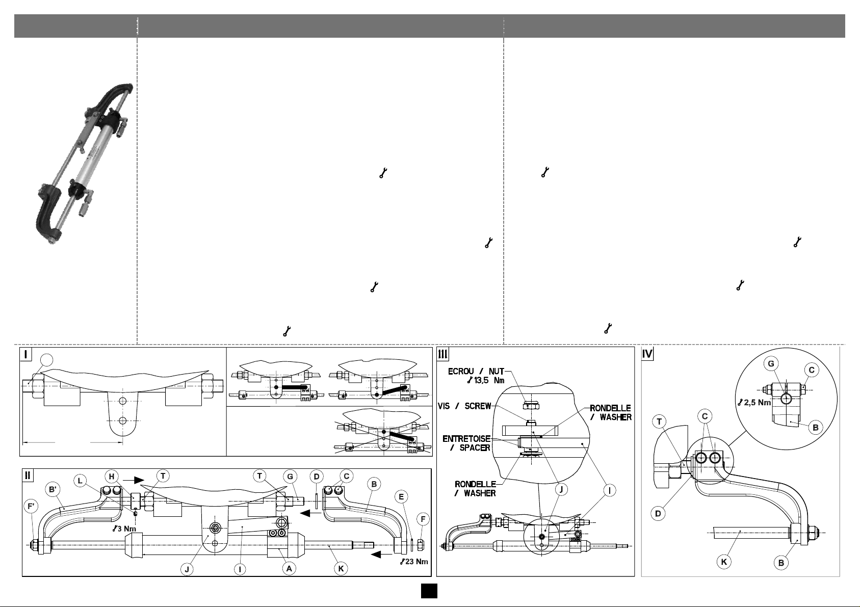
1. (Fig.I) Régler le tube fileté du moteur T à 160 mm de l'axe du
moteur.
2. (Fig.II) ! la bride A est préréglée et serrée en usine, son
réglage ne doit en aucun cas être modifié.
Désaccoupler le bras B en desserrant les vis C et en retirant les
rondelles et écrous DEF. Emmancher l'arbre G dans le tube fileté
du moteur T pour arriver en butée sur l'écrou H. Visser l'écrou H
sur le tube T sans le bloquer.
3. (Fig.III) Fixer l'attache I au levier du moteur J en respectant
l'empilage vis, rondelles, entretoise et écrou ( 13,5 Nm).
4. Raccorder les flexibles (voir page 13) puis purger la direction (voir
page 15).
5. (Fig.II) Accoupler le bras B simultanément à l'extrémité de la tige K
et de l'arbre G en insérant la rondelle D entre le bras B et le tube
fileté du moteur T. Remonter la rondelle E et bloquer l'écrou F (
23 Nm) en tenant l'écrou f.
6. (Fig.IV) S'assurer que l'extrémité de l'arbre G arrive au ras de la face
extérieure du bras B et bloquer les vis C ( 2,5 Nm).
7. (Fig.II) Terminer le montage du vérin en dévissant l'écrou H pour
l'amener en butée contre le bras b de manière à supprimer le jeu
latéral ; bloquer la vis L ( 3 Nm).
1. (Dwg I) Adjust the engine screw tube T at 160 mm from the motor axis.
2. (Dwg II) ! The flange A is pre-adjusted and tightened in factory.
Under no circumstances should this adjustment be modified.
Disconnect the bullhorn B by undoing the screws C and removing
washers and nuts DEF. Insert bullhorn G into the engine screw
tube T until it comes in contact with nut H. Screw nut H on the tube
T without locking it.
3. (Dwg III) Fix the cylinder connection lever I to the motor lever J.
Observe the correct mounting order of the screw, washers, spacer and
nut ( 13.5 Nm).
4. Connect the flexible tubes (see page 13, then bleed the steering system
(see page 15).
5. (Dwg II) Connect the bullhorn B simultaneously to the end of rod K
and shaft G by inserting washer D between the bullhorn B and the
engine screw tube T. Mount washer E and lock the nut F ( 23 Nm)
by holding nut f.
6. (Dwg IV) Make sure that the end part of shaft G is flush with the
exterior face of bullhorn B. Tighten screws C ( 2.5 Nm).
7. (Dwg II) Finalise the cylinder installation by undoing nut H and
displace it against bullhorn b in order to eliminate lateral play.
Tighten screw L ( 3 Nm).
mm
160
MONTAGE NON CONFORME
/ WRONG MOUNTING
MONTAGE CONFORME / CORRECT MOUNTING
T
10
Page 12
Instructions de montage
Mounting instructions
Type de vérin
Type of Cylinder
VHM 232 COMPACT
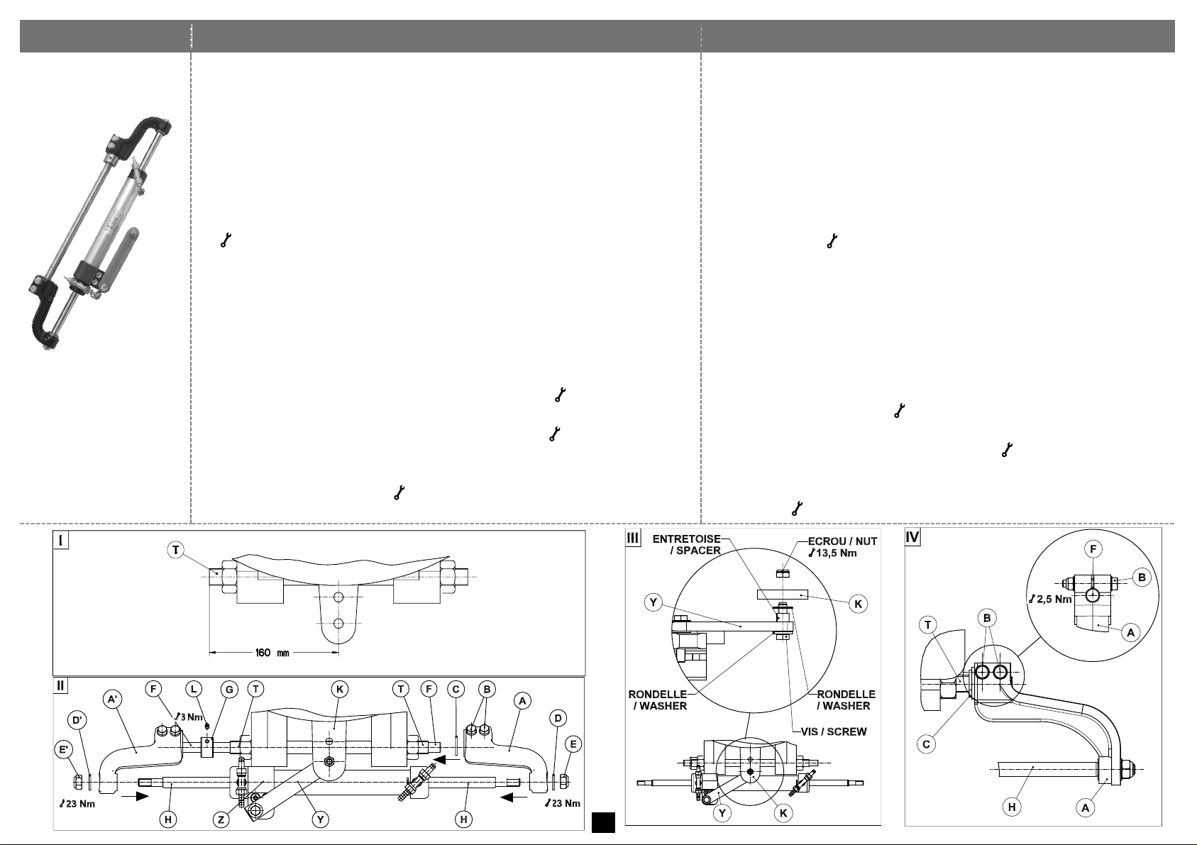
1. (Fig.I) Régler le tube fileté du moteur T à 160 mm de l'axe du moteur.
2. (Fig.II) ! la bride Z est préréglée et serrée en usine, son
réglage ne doit en aucun cas être modifié.
(Fig.II) Désaccoupler entièrement le bras A du vérin en desserrant les
vis B et en retirant les rondelles et écrous EDC. Retirer l’écrou e et
la rondelle d du bras a. Desserrer légèrement la vis L afin de retirer
l’écrou G de l’arbre F puis désaccoupler le bras a de la tige H.
3. (Fig.III) Fixer l'attache du vérin Y au trou taraudé du levier du
moteur K en respectant l'empilage vis, rondelles, entretoise et écrou
( 13,5 Nm).
4. Raccorder les flexibles (page 13) puis purger la direction (page 15)
5. (Fig.II) Visser entièrement l’écrou G sur le tube moteur T.
Présenter l’ensemble aF afin d’emmancher simultanément l’arbre
F dans le tube du moteur T et le bras a dans la tige H jusqu’à
arriver en butée sur l’écrou G. Remonter la rondelle d et l’écrou e.
Insérer la rondelle C dans l’arbre F. Emmancher simultanément le
bras A dans l’arbre F et la tige H. Remonter la rondelle D et
l’écrou E. Visser et bloquer les écrous E et e ( 23 Nm).
6. (Fig.IV) S'assurer que l'extrémité de l'arbre F arrive au ras de la
face extérieure du bras A et bloquer les vis B ( 2,5 Nm).
7. (Fig.II) Terminer le montage du vérin en dévissant l'écrou G pour
l'amener en butée contre le bras a de manière à supprimer le jeu
latéral ; bloquer la vis L ( 3 Nm).
1. (Dwg I) Adjust the engine screw tube T at 160 mm from the motor axis.
2. (Dwg II) ! The flange Z is pre-adjusted and tightened in factory.
Under no circumstances should this adjustment be modified.
(Dwg II) Remove the cylinder bullhorn A by undoing the screws Band
removing washers and nuts
EDC
. Remove nut e and its washer
d
from the bullhorn a. Slightly loosen screw L in order to remove nut G
from shaft F and then disconnect bullhorn a from rod H.
3. (Dwg III) Fix the cylinder connection plate Y to the threaded hole on
the motor lever K. Observe the mounting order of screw, washers,
spacer and nut ( 13.5 Nm).
4. Connect the flexible tubes (page 13), then bleed the steering system (page 15).
5. Dwg II) Screw nut G completely on the motor screw tube T. Prepare
and position the assembly a F in order to insert simultaneously
shaft F into the motor screw tube T and the bullhorn a on the
cylinder rod H until it comes against nut G.Put back washer d and
nut e.
Insert the washer C onto shaft F. Insert simultaneously bullhorn A
into shaft F and rod H. Reassemble the washer D and nut E. Screw
and tighten nuts E and e ( 23 Nm).
6. (Dwg IV) Make sure that the end part of shaft F is flush with the
exterior face of bullhorn A. Lock screws B ( 2.5 Nm).
7. (Dwg II) Finalise the cylinder installation by undoing nut G and
move it against bullhorn a in order to eliminate lateral play. Lock
screw L ( 3 Nm).
11
Page 13
Instructions de montage
Mounting instructions
Type de vérin
Type of Cylinder
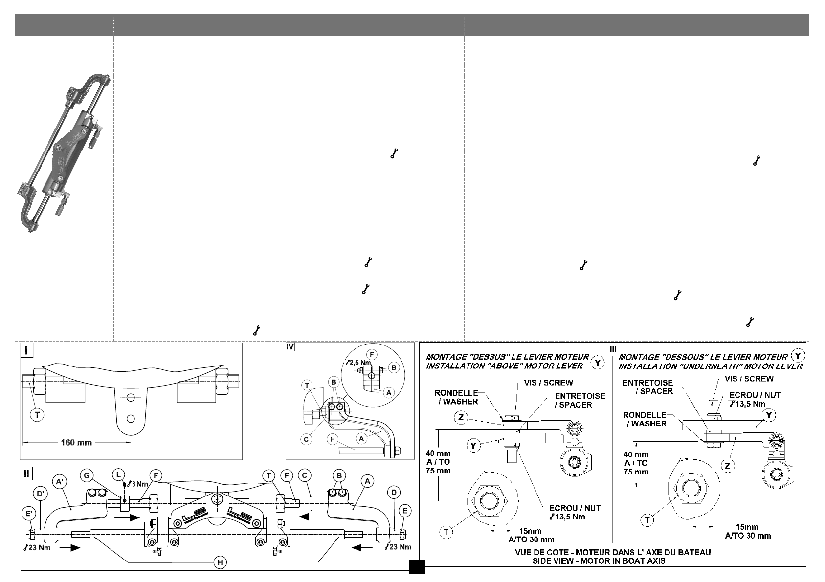
VHM EX 350 HP
VHM EX 3500 HP
1. (Fig.I) Régler le tube fileté du moteur T à 160 mm de l'axe du moteur.
2. (Fig.II) Désaccoupler entièrement le bras A du vérin en desserrant les
vis B et en retirant les rondelles et écrous EDC. Retirer l’écrou e et
la rondelle d du bras a. Desserrer légèrement la vis L afin de retirer
l’écrou G de l’arbre F puis désaccoupler le bras a de la tige H.
3. (Fig.III) En fonction du montage "Dessus" ou "Dessous", présenter le
vérin sans ses bras afin de fixer l'attache Z au levier du moteur Y.
! Respecter les cotes 40 à 75 mm et 15 à 30 mm par rapport à l'axe du tube
fileté du moteur T ainsi que l'empilage vis, rondelle, et écrou ( 13,5 Nm).
4. Raccorder les flexibles (page 13) puis purger la direction (page 15)
5. (Fig.II) Visser entièrement l’écrou G sur le tube moteur T.
Présenter l’ensemble aF afin d’emmancher simultanément l’arbre
F dans le tube du moteur T et le bras a dans la tige H jusqu’à
arriver en butée sur l’écrou G. Remonter la rondelle d et l’écrou e.
Insérer la rondelle C dans l’arbre F. Emmancher simultanément le
bras A dans l’arbre F et la tige H. Remonter la rondelle D et
l’écrou E. Visser et bloquer les écrous E et e ( 23 Nm).
6. (Fig.IV et Fig.II) S'assurer que l'extrémité de l'arbre F arrive au ras de
la face extérieure du bras A et bloquer les vis B ( 2,5 Nm).
7. (Fig.II) Terminer le montage du vérin en dévissant l'écrou G pour
l'amener en butée contre le bras a de manière à supprimer le jeu
latéral ; bloquer la vis L ( 3 Nm).
1. (Dwg I) Adjust the engine screw tube T at 160 mm from the motor central axis.
2. (Dwg II) Remove the cylinder bullhorn A by undoing the screws Band
removing washers and nuts
EDC
. Remove nut e and its washer d from
the bullhorn a. Slightly loosen screw L in order to remove nut G from
shaft F and then disconnect bullhorn a from rod H.
3. (Dwg III) In function of the installation "above" or "underneath" the motor lever,
position the cylinder without its bullhorns to connect the cylinder connection plate
Z to the motor lever Y.
! Observe the dimensions 40 to 75 mm and 15 to 30 mm from the engine screw tube
axis T and the correct mounting order of screw, washer, spacer and nut ( 13.5 Nm).
4. Connect the flexible tubes (see page 13), then bleed the steering system (see page 15)
5. Dwg II) Screw nut G completely on the motor screw tube T. Prepare
and position the assembly a F in order to insert simultaneously shaft F
into the motor screw tube T and the bullhorn a on the cylinder rod H
until it comes against nut G.Put back washer d and nut e.
Insert the washer C onto shaft F. Insert simultaneously bullhorn A into
shaft F and rod H. Reassemble the washer D and nut E. Screw and
tighten nuts E and e ( 23 Nm).
6. (Dwg IV and Dwg II) Make sure that the end part of shaft F is flush with the
exterior face of bullhorn A. Tighten screws B ( 2.5 Nm).
7. (Dwg II) Finalise the cylinder installation by undoing nut G and displace it against
bullhorn a in order to eliminate the lateral play. Tighten screw L ( 3 Nm).
12
Page 14
TYPES DE RACCORDEMENTS
• Par collier de serrage
• Par raccord à visser
• Par raccord à sertir
• Par raccord et flexible présertis
TYPES OF CONNECTION
• Clamp fitting
• Screwed connection
• Crimp connection
• Swaged Fittings and Flexible Tubes with Swaged Fittings
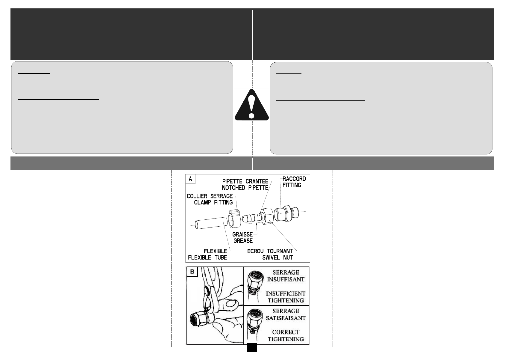
Par collier de serrage
Clamp fitting
Figure A :
▪ Séparer l’écrou tournant et la pipette crantée
du raccord.
▪ Visser la partie raccord sur les utilisations de
la pompe en respectant les couples de
serrage indiqués.
▪ Graisser la pipette crantée.
▪ Passer le flexible dans le collier.
▪ Emmancher le flexible sur la pipette crantée
jusqu’à 1 mm de l’écrou tournant.
Drawing A :
▪ Loosen the swivel nut and the pipette from
the fitting.
▪ Screw the fitting (union piece) in the pump
outlets as per the indicated torque.
▪ Grease the notched pipette.
▪ Insert the tube through the clamp.
▪ Push the tube on the notched pipette up to
1 mm from the swivel nut.
Figure B :
▪ Placer le collier à environ 3 à 5 mm de la face
de l’écrou tournant et le sertir.
▪ Remonter l’écrou tournant sur le raccord de la
pompe (couple de serrage 6 Nm) tout en
maintenant le raccord avec une clé plate.
Drawing B :
▪ Move the clamp to approx. 3 to 5 mm from
the swivel nut and crimp it.
▪ Tighten the swivel nut on the fitting, while
holding the fitting with a spanner (torque =
6 N.m).
Raccords
Ne pas utiliser de raccords coniques. Ils doivent être
nettoyés avant tout raccordement.
Sertissage des flexibles
La coupe des flexibles devra être franche et perpendiculaire.
Ne pas couper les flexibles trop courts : tenir compte du
déplacement du vérin et des rayons de courbure minimum
(R 90 mm).
Aucune impureté ne doit pénétrer dans les flexibles. Ils
doivent être nettoyés avant tout raccordement.
13
Fittings
Do not use conic fittings. They should be cleaned prior to
connection.
Crimping of Flexible Tubes
Make a clean and perpendicular cut on the flexible tubes.
Do not cut them too short to allow for the cylinder displacement
and the minimum bending radius of the pipes (R 90 mm).
No impurities are to enter the pipes. They should be cleaned prior
to connection.
Page 15
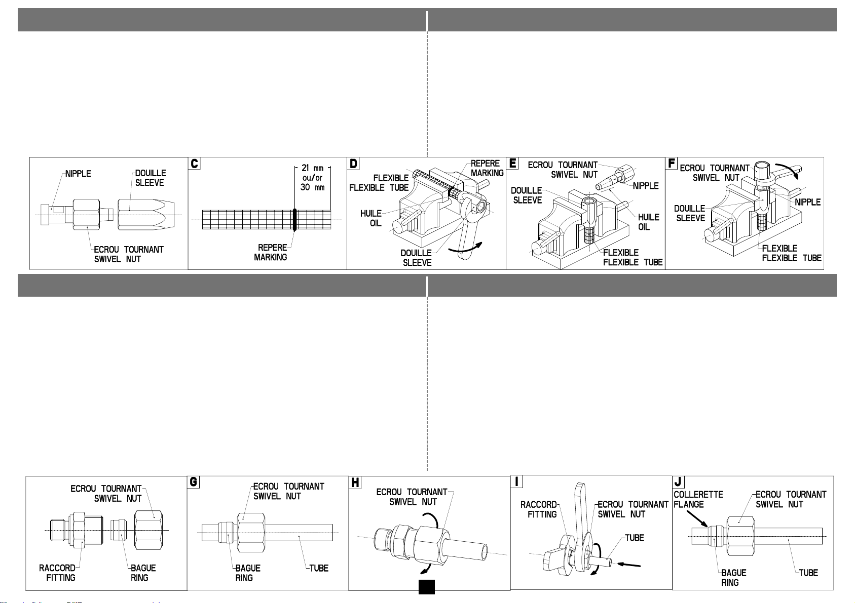
Par raccord à visser
Screwed connection
▪ Séparer l’écrou tournant, la douille et la nipple du raccord.
▪ Visser la partie raccord sur les utilisations de la pompe en respectant les
couples de serrage indiqués.
▪ Tracer un repère à 21 mm pour int. 8 mm ou à 30 mm pour int. 10 mm
(Fig. C).
▪ Huiler le bout du flexible et le bloquer en rotation sans l’écraser (Fig. D).
▪ Visser la douille jusqu’au repère, sens de rotation anti-horaire (Fig. D).
▪ Placer la douille dans l’étau (Fig. E) et huiler la nipple.
▪ Visser la nipple jusqu’à la limite du filetage, sens de rotation horaire (Fig. F).
▪ Separate the swivel nut, the sleeve and the nipple from the fitting.
▪ Screw the fitting (union piece) in the pump outlets as per the indicated torque.
▪ Mark a point of reference at 21 mm for 8 mm inner Ø tube or 30 mm for
10 mm inner Ø tube (Dwg C).
▪ Lubricate the end of the hose and immobilize it without squeezing it (Dwg
D).
▪ Screw the sleeve up to the marking in anticlockwise direction (Dwg D).
▪ Immobilize the sleeve in a vice (Dwg E) and lubricate the nipple.
▪ Screw the nipple to the thread end in clockwise direction (Dwg F).
Par raccord à sertir
Crimp connection
▪ Séparer l’écrou tournant et la bague des raccords.
▪ Visser la partie raccords sur les utilisations de la pompe en respectant les
couples de serrage indiqués.
▪ Glisser l’écrou tournant et la bague sur le tube (Fig. G).
▪ Visser l’écrou tournant jusqu’en début de butée (Fig. H).
▪ Enfoncer fermement le tube dans le corps du raccord jusqu’en butée.
Puis à l’aide d’une clé, serrer l’écrou tournant d’environ 1 ½ tour (Fig. I).
▪ Contrôle : démonter l’écrou tournant. Une collerette visible doit remplir
l’espace situé devant la face avant de l’arête. La bague peut tourner, mais
aucun déplacement axial n’est autorisé (Fig. J).
Remontage : visser l’écrou tournant sur le raccord jusqu’en début de butée
puis serrer d’environ 1/8 de tour à l’aide d’une clé.
▪ Separate the swivel nut and the ring from the fittings.
▪ Screw the fittings (union pieces) in the pump outlets as per the indicated torque.
▪ Slip the swivel nut and the ring on the tube (Dwg G).
▪ Screw on the swivel nut until it makes contact. Do not tighten. (Dwg H).
▪ Firmly insert the tube inside the fitting until it comes to a stop. Tighten the
swivel nut with a spanner by approximately 1 ½ turn (Dwg I).
▪ Checking: loosen the swivel nut. A visible flange must occupy the space in
front of the edge front face. The ring can turn but no axial movement is
allowed (Dwg J).
Reassembly: screw on the swivel nut until it makes contact, then tighten it by
about 1/8 turn with a spanner.
14
Page 16
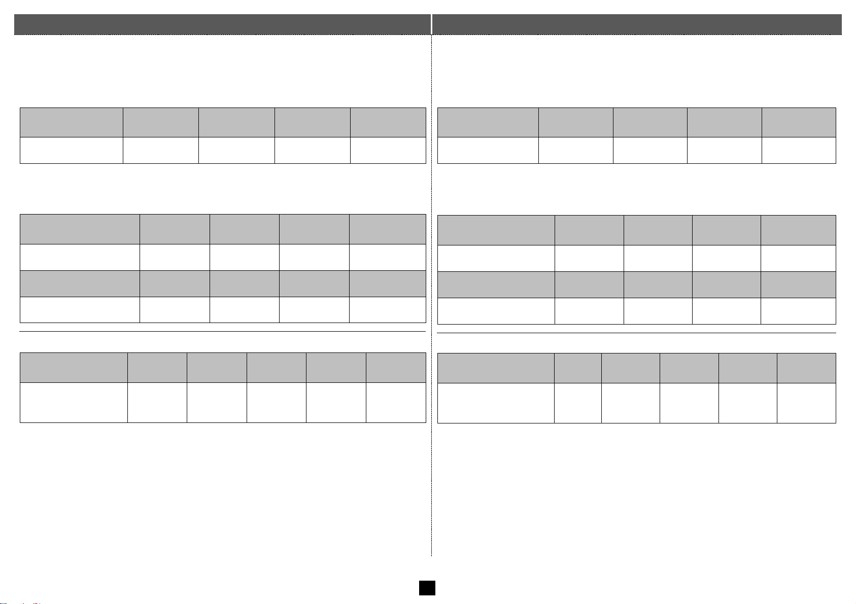
Par raccord et flexible présertis
Swaged Fittings and Flexible Tubes with Swaged Fittings
▪ Enlever les bouchons de protection sur le vérin et les raccords.
▪ Visser le raccord sens horaire, joint du raccord vers le vérin puis le
serrer. Pour les raccords coudés orientables, se reporter à la page 16.
1/8’ BSPP
1/4’ BSPP
3/8’ BSPP
1/2’ BSPP
" Nm
9
35
45
65
▪ Enlever le bouchon de protection du flexible.
▪ Visser le flexible sens horaire sur le raccord puis le serrer.
▪ Répéter la même opération avec l’autre flexible.
Série raccord
10 L
12 L
15 L
17 L
" Nm
35
45
55
65
Série raccord
18 L
21 L
JIC 7/8
JIC 9/16
" Nm
65
90
85
28
Série Ø flexible
DN8
DN10
DN13
DN16
DN19
Rayon courbure mini
(mm)
90
110
150
175
215
▪ Remove the protective caps from the cylinder and fittings.
▪ Screw the fitting clockwise into the pump with the fitting seal on the
cylinder side then tighten it. For swivel elbow fittings, see page 16.
1/8’ BSPP
1/4’ BSPP
3/8’ BSPP
1/2’ BSPP
" Nm
9
35
45
65
▪ Remove the protective cap from the flexible tube.
▪ Screw the flexible tube clockwise on the fitting and tighten it.
▪ Repeat the same operation with the other flexible tube.
Fittings Range
10 L
12 L
15 L
17 L
" Nm
35
45
55
65
Fittings Range
18 L
21 L
JIC 7/8
JIC 9/16
" Nm
65
90
85
28
Flexible tubes Range Ø
DN8
DN10
DN13
DN16
DN19
Minimum Bending
Radius (mm)
90
110
150
175
215
15
Page 17

Montage des raccords coudés orientables ¼ BSPP male +
joint – male JIC 9/16
Instructions for reorienting the ¼ male cylindrical swivel
elbow fitting(s) + seal - male JIC 9/16
1- Visser le raccords à la main.
2- Puis à l’aide d’une clé, visser le raccord jusqu’à ce que les rondelles et
le joint torique soient remontés en butée dans leurs logements et en
contact avec le corps du vérin.
3- !S’assurer que le joint torique soit en position haute de son
logement.
4- Puis à l’aide de la même clé, visser le raccord d’un tour maxi à la
position souhaitée.
5- Serrer le contre-écrou ( 35 Nm).
1- Screw the fitting by hand.
2- Then, using a spanner, screw in the fitting until the washers and O-ring
are back in their seats and in contact with the cylinder body.
3- !Check that the O-ring is in the upper position of its housing.
4- Then, using the same spanner, screw the fitting back to the desired
position by one turn maximum.
5- Tighten the locknut ( 35 Nm).
Instruction pour réorienter le ou les raccords coudés
orientables ¼ BSPP male + joint – male JIC 9/16
Instructions for reorienting the ¼ male cylindrical swivel
elbow fitting(s) + seal - male JIC 9/16
1- Dévisser le contre-écrou.
2- Dévisser le raccord orientable
maximum de ½ tours (180°).
Si la présence d’un purgeur
empêche de dévisser le raccord
orientable (VHM EX3500 HP),
dévisser le purgeur et le retirer.
! Ne jamais visser le raccord
orientable pour le réorienter,
cela peut entrainer la
destruction du joint.
3- Serrer le contre-écrou ( 35 Nm).
4- Si besoin, visser le purgeur
préalablement retiré ( 3,5 Nm).
1- Unscrew the lock nut.
2- Unscrew the swivel elbow
fitting by up to ½ turn (180°).
If the presence of a bleeder
cook prevents swivel elbow
fitting from being unscrewed
(VHM EX3500 HP), unscrew
the bleeder cook and remove it.
! Never screw swivel elbow
fitting to reorient it, as this
may destroy the seal.
3- Tighten the lock nut ( 35 Nm).
4- If necessary, screw on the
drain valve previously removed
( 3.5 Nm).
16
Page 18
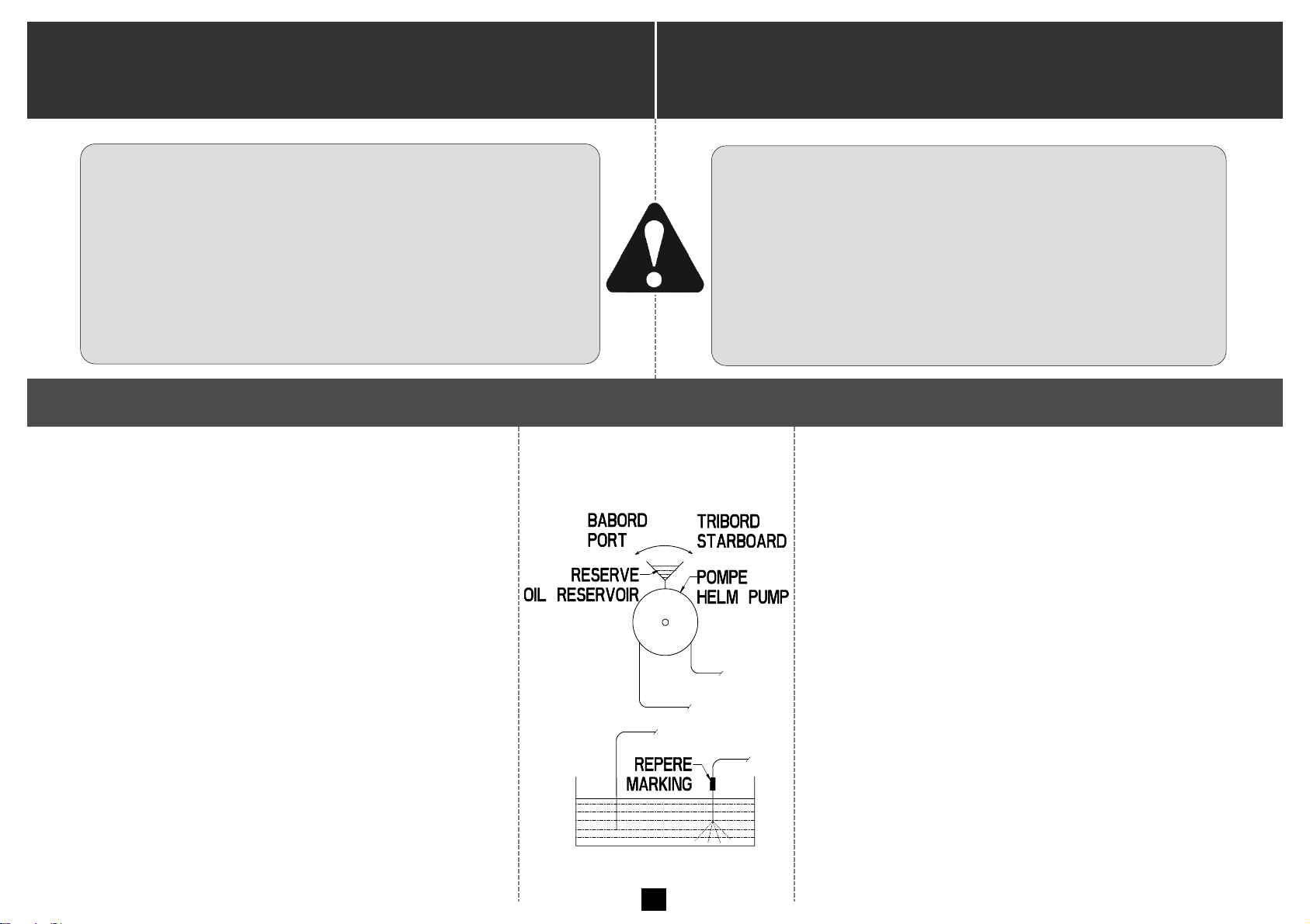
REMPLISSAGE ET PURGE DE VOTRE DIRECTION
Simples postes de pilotage
Doubles postes de pilotage
FILLING UP AND BLEEDING YOUR STEERING SYSTEM
Single steering Station Systems
Double steering Station Systems
Opération commune pour les simples postes de pilotage / Procedure Applying to Single Steering Station Systems
▪ Brancher les flexibles d’utilisation sur la pompe et
plonger l’autre extrémité des flexibles dans un
récipient d’huile.
▪ Installer une réserve sur la pompe et la maintenir
constamment remplie d’huile pendant la purge du
circuit.
▪ Faire tourner la pompe lentement côté tribord (environ
quinze tours en fonction de la longueur de votre
circuit). Lorsque le flexible ne rejette plus d’air,
repérer ce flexible (voir figure).
▪ Faire tourner la pompe côté bâbord jusqu’à ce qu’il n’y
ait plus d’air qui sorte du flexible non repéré.
Pour la suite de la purge reportez-vous au paragraphe A
ou B selon votre modèle de direction.
▪ Connect the utilization tubes to the pump and put the
other ends of the tubes into an oil reservoir.
▪ Put an oil reservoir on the pump and keep it full of oil
during the bleeding operation.
▪ Slowly turn the pump steering wheel to starboard (by
about 15 turns in function of your circuit length). Once
there is no air coming out of the tube mark this flexible
tube (see drawing).
▪ Turn the pump steering wheel to port until there is no
air coming out of the unmarked flexible tube.
To pursue the bleeding procedure, see paragraph A or B
in function of your steering model.
Utiliser uniquement de l’huile DEXRON II (ATF DII).
Assurez-vous dans tous les cas que votre
tuyauterie et votre huile restent parfaitement
propres, toutes impuretés pouvant entraîner une
détérioration des organes de la direction
hydraulique.
Only use oil DEXRON II (ATF DII).
Make sure that the hydraulic piping is perfectly clean
and keep the oil free from impurities which may
cause the deterioration of the components of your
hydraulic steering system.
17
Page 19
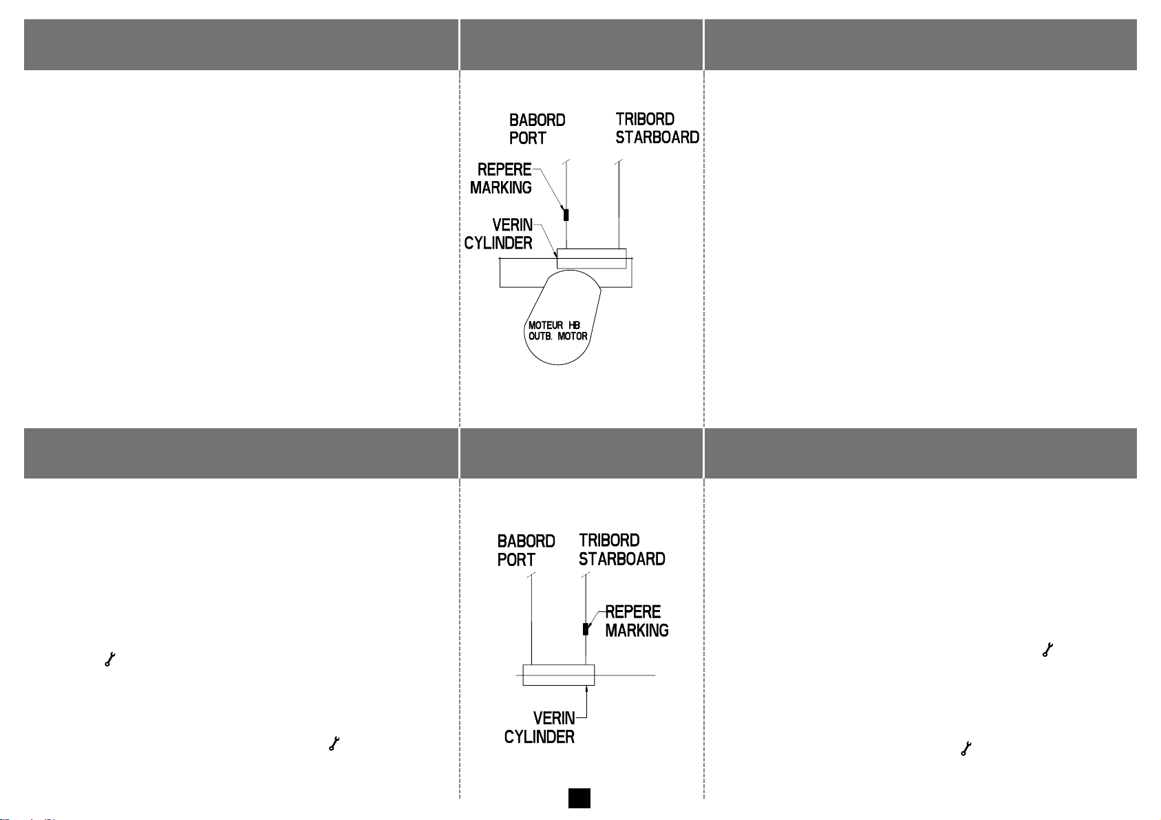
A) Direction hors-bord (montage frontal)
A) Outboard Steering (front mount)
▪ Positionner le vérin de façon à ce que la tige soit
entièrement sortie côté bâbord de votre bateau.
▪ Brancher le flexible repéré au vérin, côté tige sortie.
▪ Brancher le flexible non repéré au vérin côté tige
rentrée et ouvrir le purgeur bâbord (côté tige sortie).
▪ Faire tourner la pompe lentement côté tribord et lorsqu’il
ne sort plus d’air du purgeur bâbord, le fermer.
▪ Ouvrir le purgeur tribord (côté tige rentrée).
▪ Faire tourner la pompe lentement côté tribord jusqu’à
ce que la tige soit complètement sortie côté tribord.
▪ Faire tourner la pompe lentement côté bâbord et lorsqu’il
ne sort plus d’air du purgeur tribord, le fermer.
Pour la suite reportez-vous au paragraphe E puis
retournez aux instructions de montage de votre vérin.
▪ Position the cylinder so that the cylinder rod fully comes out
on port side on the boat.
▪ Connect the marked flexible tube to the cylinder on the side
where the rod is extended.
▪ Connect the unmarked flexible tube to the cylinder on the side
where the rod is retracted and open the bleeder cock on the port
side (rod extended side).
▪ Turn the steering wheel slowly to starboard. Once no air
comes out anymore from the port bleeder cock, close it.
▪ Open the bleeder cock on starboard (rod retracted side).
▪ Turn the steering wheel slowly to starboard until the rod is
fully extended to starboard.
▪ Turn the steering wheel slowly to port. Once no air comes
out anymore from the starboard bleeder cock, close it.
See paragraph E for continuation, then go back to the cylinder
mounting instructions.
B) Direction hors-bord (montage latéral)
et Z-Drive
B) Outboard Steering (side mount)
and Z-Drive
▪ Positionner le vérin de façon à ce que la tige soit
entièrement sortie côté tribord de votre bateau.
▪ Brancher le flexible repéré au vérin, côté tige sortie.
Ne pas ouvrir le purgeur côté tribord.
▪ Brancher le flexible non repéré au vérin, côté tige
rentrée et ouvrir le purgeur côté bâbord.
▪ Faire tourner la pompe lentement côté bâbord et
lorsqu’il ne sort plus d’air du purgeur côté bâbord, le
fermer ( 3,5 Nm).
▪ Ouvrir le purgeur tribord côté tige sortie.
▪ Faire tourner la pompe lentement côté tribord et lorsque
la tige s’est complètement déplacée et qu’il ne sort plus
d’air du purgeur côté tribord, le fermer ( 3,5 Nm).
Pour la suite reportez-vous au paragraphe E.
▪ Position the cylinder so that the cylinder rod fully comes
out on your boat starboard side.
▪ Connect the marked flexible tube to the cylinder on the
side where the rod is extended. Do not open the
starboard bleeder cock.
▪ Connect the unmarked flexible tube to the cylinder on the
side where the rod is retracted. Open the po rt bleeder cock.
▪ Turn the steering wheel slowly to port and once no air comes
out anymore from the port bleeder cock, close it ( 3,5 Nm).
▪ Open the starboard bleeder cock on the side where the
cylinder rod is extended.
▪ Turn the steering wheel slowly to starboard. Once the cylinder
rod has fully moved to the other side and no air comes out of
the starboard bleeder cock, close it ( 3,5 Nm).
See paragraph E for continuation.
18
Page 20
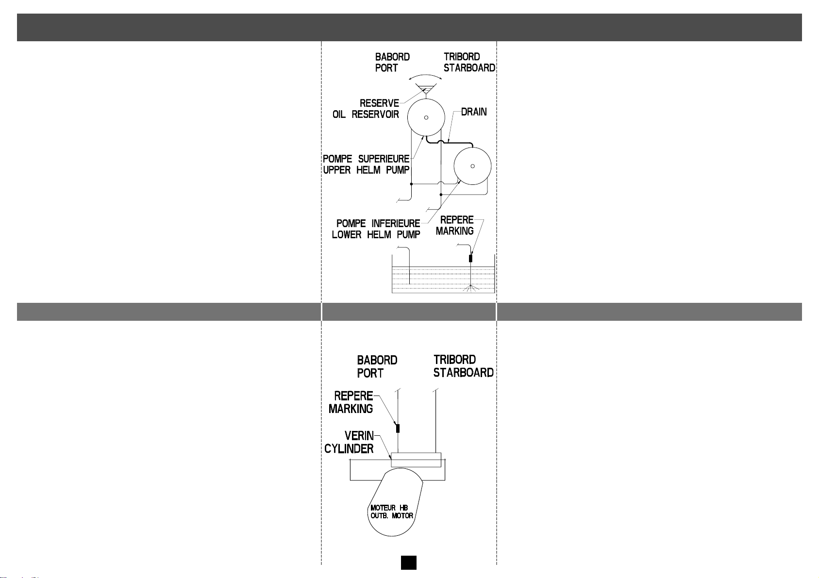
Opération commune pour les doubles postes de pilotage / Procedure Applying to Double Steering Station Systems
▪ Brancher les flexibles d’utilisation sur les pompes et plonger
l’autre extrémité des flexibles dans un récipient d’huile.
▪ Brancher le drain entre les deux pompes.
▪ Installer une réserve sur la pompe supérieure et la
maintenir constamment remplie d’huile pendant la
purge du circuit.
▪ Ouvrir le bouchon de remplissage de la pompe inférieure et
lorsque la pompe est remplie d’huile remettre le bouchon.
▪ Faire tourner la pompe supérieure lentement côté tribord
(environ quinze tours en fonction de la longueur de votre
circuit) puis la pompe inférieure lentement côté tribord.
Lorsque le flexible ne rejette plus d’air, repérer ce flexible
(voir fig.).
▪ Faire tourner la pompe inférieure côté bâbord, puis la
pompe supérieure lentement côté bâbord, jusqu’à ce qu’il
n’y ait plus d’air qui sorte du flexible non repéré.
Pour la suite de la purge reportez-vous au paragraphe C ou D
selon votre modèle de direction.
▪ Connect the utilization tubes to the pumps and put the other
ends of the tubes into an oil reservoir.
▪ Connect the drain between the two pumps.
▪ Put an oil reservoir on the upper pump and keep it full of
oil during the bleeding operation.
▪ Open the filler cap on the lower helm pump. Once the pump
is full of oil put back the filler cap.
▪ Turn the upper pump steering wheel slowly to starboard (by
about 15 turns in function of your circuit length) and then
turn the lower pump slowly to starboard. Once there is no
air coming out from the flexible tube, mark this tube (see
drawing).
▪ Turn the lower pump steering wheel to port and then the
upper pump slowly to port until there is no air coming out
from the unmarked flexible tube.
To pursue the bleeding procedure, go to paragraph C or D in
function of your steering model.
C) Direction hors-bord (montage frontal)
C) Outboard Steering (front mount)
▪ Positionner le vérin de façon à ce que la tige soit
entièrement sortie côté bâbord de votre bateau.
▪ Brancher le flexible repéré au vérin, côté tige sortie.
▪ Brancher le flexible non repéré au vérin, côté tige
rentrée et ouvrir le purgeur côté bâbord (côté tige
sortie).
▪ Faire tourner la pompe supérieure lentement côté
tribord, puis la pompe inférieure lentement côté
tribord. Lorsqu’il ne sort plus d’air du purgeur côté
bâbord, le fermer.
▪ Ouvrir le purgeur tribord (côté tige rentrée).
▪ Faire tourner la pompe inférieure lentement côté
tribord jusqu’à ce que la tige du vérin soit entièrement
sortie côté tribord, puis la pompe supérieure
lentement côté tribord jusqu’à ce qu’il ne sorte plus
d’air du purgeur côté tribord.
▪ Position the cylinder so that the cylinder rod fully comes
out on your boat port side.
▪ Connect the marked flexible tube to the cylinder on the
side where the rod is extended.
▪ Connect the unmarked flexible tube to the cylinder on the
side where the rod is retracted. Open the port bleeder
cock (rod extended side).
▪ Turn the upper steering wheel slowly to starboard and then
the lower steering wheel slowly to starboard. Once no air
comes out anymore from the port bleeder cock, close it.
▪ Open the starboard bleeder cock (rod retracted side).
▪ Turn the lower steering wheel slowly to starboard until
the cylinder rod is fully extended to starboard. Then
turn the upper steering wheel slowly to starboard until
no air comes out from the starboard bleeder cock.
19
Page 21
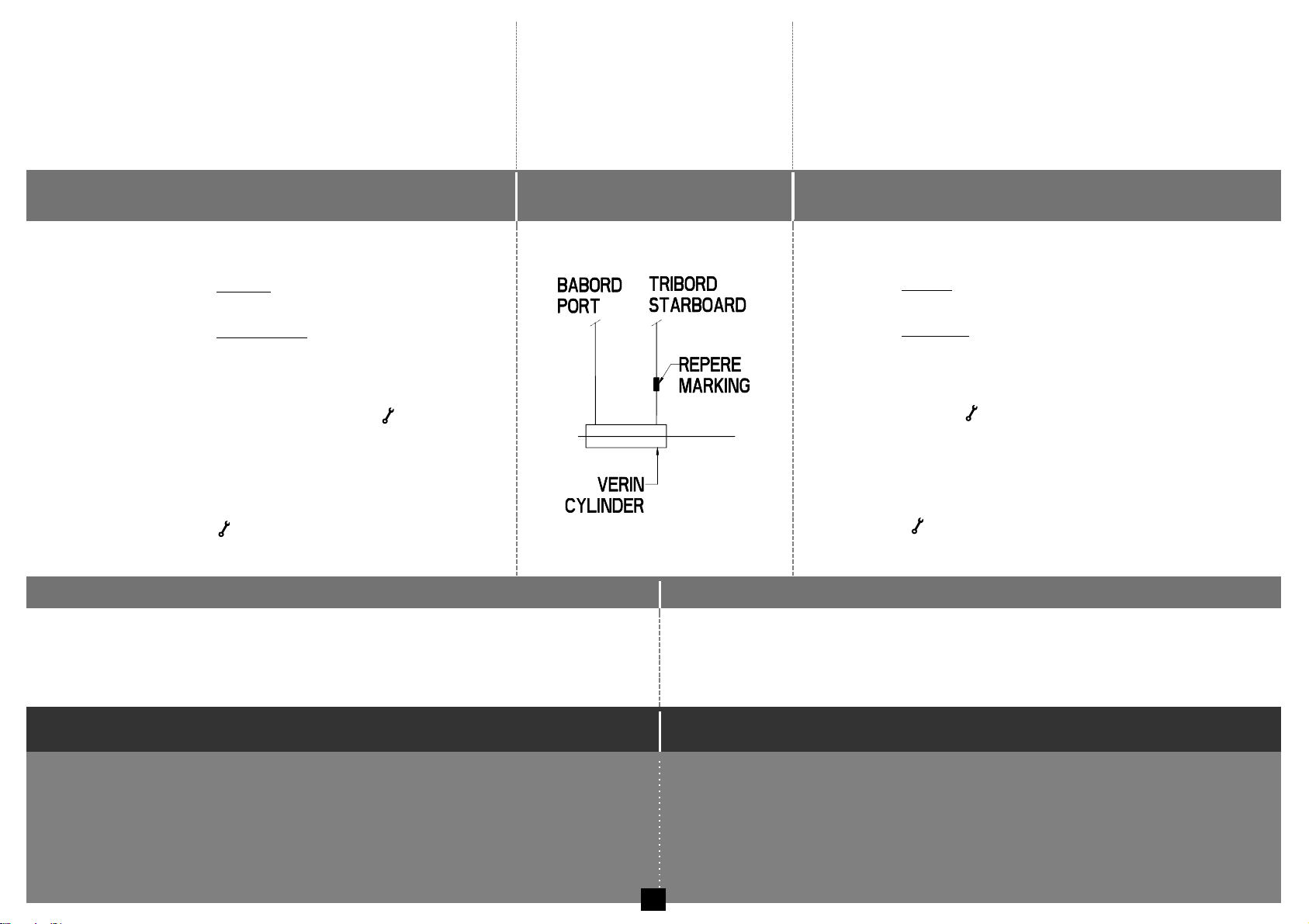
▪ Faire tourner la pompe inférieure lentement côté
bâbord, puis la pompe supérieure lentement côté
bâbord. Lorsqu’il ne sort plus d’air du purgeur côté
tribord, le fermer.
Pour la suite reportez-vous au paragraphe E puis
retournez aux instructions de montage de votre vérin.
▪ Turn the lower steering wheel slowly to port and then
turn the upper steering wheel slowly to port. Once no
air comes out from the starboard bleeder cock, close it.
See paragraph E for continuation, then go back to the cylinder
mounting instructions.
D) Direction hors-bord (montage latéral),
Z-Drive, Inbord (safran)
D) Outboard Steering (side mount),
Z-Drive, Inboard (rudder)
▪ Positionner le vérin de façon à ce que la tige soit
entièrement sortie côté tribord de votre bateau.
▪ Brancher le flexible repéré au vérin, côté tige sortie.
Ne pas ouvrir le purgeur côté tribord.
▪ Brancher le flexible non repéré au vérin, côté tige
rentrée et ouvrir le purgeur côté bâbord.
▪ Faire tourner lentement la pompe supérieure côté
bâbord, puis la pompe inférieure. Lorsqu’il ne sort plus
d’air du purgeur côté bâbord, le fermer ( 3,5 Nm).
▪ Ouvrir le purgeur tribord côté tige sortie.
▪ Faire tourner lentement la pompe inférieure côté
tribord, puis la pompe supérieure. Lorsque la tige s’est
complètement déplacée et qu’il ne sort plus d’air du purgeur
côté tribord le fermer ( 3,5 Nm).
Pour la suite reportez-vous au paragraphe E.
▪ Position the cylinder so that the cylinder rod fully comes out on
your boat starboard side.
▪ Connect the marked flexible tube to the cylinder on the side where
the rod is out. Do not open the bleeder cock on starboard side.
▪ Connect the unmarked flexible tube to the cylinder on the side where
the rod is in. Open the bleeder cock on port side.
▪ Slowly turn the upper pump steering wheel to port and then the
lower pump. Once no air comes out anymore of the bleeder cock
on port side, close it ( 3,5 Nm).
▪ Open the bleeder cock on starboard side where the cylinder rod is out.
▪ Slowly turn the lower pump steering wheel on starboard side and
then the upper pump. Once the cylinder rod has fully moved to the
other side and no air comes out of the bleeder cock on starboard
side, close it ( 3,5 Nm).
See paragraph E for continuation.
E) Opérations finales simples et doubles postes de pilotage
E) Final Check List for Single and Twin Steering Stations
▪ Retirer la réserve d’huile préalablement installée sur la pompe.
▪ Faire le niveau d’huile en laissant environ 25 mm d’air dans la pompe.
▪ Visser le bouchon de remplissage livré dans la pochette de fixation.
▪ Diamètre de roue conseillée = voir tableau « diamètres conseillés ».
▪ Remove the oil reservoir previously installed on the pump.
▪ Fill up the oil in the helm pump by leaving a 25 mm air gap on top.
▪ Screw on the filler cap provided in the mounting kit.
▪ Recommended wheel diameter: see table “Recommended diameters”
Vérification du bon fonctionnement
Test Check Operation
▪ Qu'une rotation du volant à droite (SH) ou tribord, déplace le bateau vers tribord.
▪ Que le circuit est bien purgé.
▪ Qu’il n’y a pas de fuite aux raccords, aux pompes, au vérin et aux flexibles.
▪ Que la pompe est correctement remplie d’huile.
▪ Que les écrous et vis sont bien serrés aux couples indiqués.
▪ Que les flexibles décrivent des courbes normales et qu’ils ne sont pas aplatis.
▪ Toutes ces vérifications sont nécessaires après chaque hivernage.
▪ Check that the rotation of the wheel clockwise to starboard, displaces the boat to starboard.
▪ Check that the circuit has been correctly bled.
▪ Check that the connections, the pumps, the cylinder and the flexible tubes are not leaking.
▪ Check that the oil level in the pump is correct.
▪ Check that the nuts and screws are tightened at the indicated torque.
▪ Check that the tubes follow a normal path without loops and are not squeezed.
▪ These verifications should be carried out after every wintering period.
20
Page 22
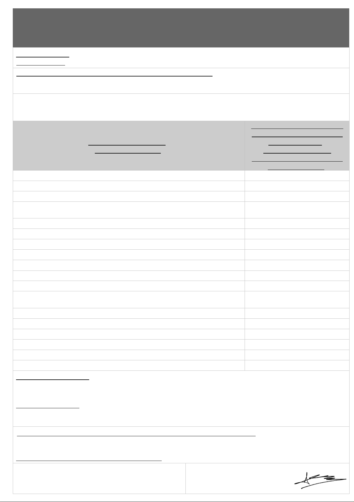
DECLARATION DE CONFORMITE DE MECANISMES DE DIRECTION AUX EXIGENCES DE LA
DIRECTIVE EUROPEENNE 2013/53/UE DU 20 NOVEMBRE 2013
DECLARATION OF CONFORMITY FOR STEERING MECHANISMS COMPLYING WITH THE
REQUIREMENTS OF EUROPEAN DIRECTIVE 2013/53/UE OF 20 NOVEMBRE 2013
Type de produits : Vérins pour appareil à gouverner.
Type of Products: Hydraulic cylinders for steering system.
Nom et adresse du fabricant / Manufacturer’s Name and Address:
SAS Lecomble et Schmitt
156 Route de Briscous - 64240 URT - FRANCE
La présente déclaration de conformité est délivrée sous la seule responsabilité de la société
Lecomble & Schmitt.
This declaration of conformity is issued under the sole responsibility of the company Lecomble & Schmitt.
Références des produits :
References of Products:
N° attestation « CE de type »
émise par l’organisme notifié
décrit ci-dessous :
“EC type” examination
certificate number issued by the
notified body below:
2200805, 2200830, 2201884, 2201912, 2202707, 2202817, 2202830
BE LSM 16111 G
2200020, 2200264, 2200322, 2200391, 2201854, 2201886, 2202724
BE LSM 16112 G
2200596, 2200696, 2201853, 2201888, 2202214, 2202725, 2202809
BE LSM 16113 G
2200033, 2200196, 2200265, 2200354, 2200358, 2200546, 2200571,
2202764, 2202833, 2202982
BE LSM 16114 G
2200344, 2200460, 2200608, 2202085, 2202086
BE LSM 16115 G
2200345, 2200357, 2200424
BE LSM 16116 G
2201768
BE LSM 16137 G
2201981, 2202105, 2202195, 2202307, 2202414, 2202770
BE LSM 16139 G
2203057, 2203167, 2203169
BE LSM 16140 G
2202275, 2202308, 2202828, 2202978, 2203036
BE LSM 16141 G
2203059, 2203123, 2203138, 2203256
BE LSM 16142 G
2202114, 2202829, 2202979, 2203037, 2203061, 2203125, 2203227,
2203257
BE LSM 16154 G
2202754, 2202839, 2203054, 2203062, 2203127
BE LSM 16156 G
2203315, 2203381, 2203382, 2203383, 2203523
BE LSM 16159 G
2203333, 2203384, 2203385, 2203386, 2203387
BE LSM 16160 G
2203334, 2203388, 2203389, 2203779, 2204016, 2204094
BE LSM 16161 G
2203335, 2203390, 2203391, 2203807, 2204017
BE LSM 16162 G
2203572, 2203573, 2203574
BE LSM 16163 G
Procédure d’évaluation : Examen « CE de type » (Modules B et C)
Ces produits sont conformes aux exigences de la directive Européenne 2013/53/UE du 20 Novembre
2013 (Annexe I, 5.4 Direction, 5.4.1 Généralités)
Evaluation Procedure: « EC type » Examination Certificate (Modules B and C)
These products comply with the requirements of European directive 2013/53/UE of 20 Novembre 2013 (Annex I,
5.4 Steering System, 5.4.1 General)
Nom et adresse de l’organisme notifié / Name and Address of the Notified Body:
Institut pour la Certification et la Normalisation dans le Nautisme
40, avenue du Lazaret – 17000 LA ROCHELLE – FRANCE
N° de l’organisme notifié / Notified body number: 0607
Arnaud RISS
Directeur Général de la société Lecomble & Schmitt
Managing Director- Lecomble & Schmitt
15 Juin 2022 / 15 June 2022
A / In Urt
Signature :
Page 23

NOTES
Page 24

GARANTIE
1) Le constructeur garantit les matériels vendus et fournis par lui contre
tout vice ou défaut de fabrication et de fonctionnement, qu’ils
proviennent d’un défaut dans la conception, les matières premières,
la fabrication ou l’exécution et cela sous les conditions et dans les
limites ci-après :
2) La garantie n’est applicable que si le client a satisfait aux obligations
générales du présent contrat et en particulier aux conditions de
paiement.
3) La garantie est strictement limitée aux fournitures vendues par le
constructeur. Elle ne s’étend pas aux matériels dans lequel les
fournitures seraient incorporées et, en particulier, aux performances
de ces matériels.
4) Lorsque les fournitures du constructeur sont incorporées par le client,
ou un tiers, à un quelconque matériel, ceux-ci sont seuls
responsables de l’adaptation, du choix et de l’adéquation des
fournitures du constructeur, les schémas, études et projets du
constructeur n’étant donnés, sauf stipulations particulières dans
l’acceptation de la commande, qu’à titre indicatif. Le constructeur ne
garantit en particulier ni les éléments et matériels non vendus par lui,
ni contre les défauts de montage, d’adaptation, de conception, de
relation et de fonctionnement de l’ensemble ou des parties de
l’ensemble ainsi créés. Les fournitures du constructeur, de même que
l’ensemble créé par le client ou un tiers, sont présumés exploités et
utilisés sous la direction et le contrôle exclusif du client ou du tiers.
5) La durée de garantie est de dix huit mois à compter de la date de la
première utilisation par le consommateur d’origine ou vingt quatre
mois à partir de la date de livraison des produits au transporteur, au
distributeur ou grossiste. Le constructeur est en droit d’exiger du client
la justification de la date de mise en service indiquée sur la demande
de garantie. Ce délai n’est ni prorogé ni interrompu par la réclamation
amiable ou judiciaire du client. A l’expiration de ce délai, la garantie
cesse de plein droit.
6) L’obligation de garantie du constructeur ne pourra jouer que si le
client établit que le vice s’est manifesté dans les conditions d’emploi
normalement prévues pour le type de fourniture, ou indiquées par le
constructeur par écrit, et en cours d’utilisation normale. Elle ne
s’applique pas en cas de faute de l’utilisateur, négligence,
imprudence, défaut de surveillance ou d’entretien, inobservation des
consignes de préconisation ou d’emploi, utilisation d’une huile de
qualité insuffisante. La responsabilité du constructeur est dégagée
pour tous dégâts provoqués par pertes d’huile ou fuites. Toute
garantie est également exclue pour des incidents résultants de cas
fortuits ou de force majeure, ainsi que pour les détériorations,
remplacements ou réparations qui résulteraient de l’usure normale du
matériel.
7) La garantie est limitée dans l’obligation de remettre en état dans les
ateliers du constructeur, à ses frais et dans le meilleur délai possible,
les matériels et pièces fournis par lui, reconnus défectueux par ses
services techniques, et qui lui auront été adressés franco, sans qu'il
puisse lui être réclamé aucune indemnité pour tout préjudice subi, tel
que accident aux personnes, dommages à des biens autres que
ceux formant l'objet du présent contrat, privation de jouissance, perte
d'exploitation, préjudice commercial ou manque à gagner. Durant la
période de garantie , les frais de main d’œuvre, de démontage et de
remontage du matériel hors des ateliers du constructeur, les frais de
transfert du matériel défectueux ou remplacé ou réparé, les frais de
voyage et de séjour des techniciens sont à la charge du client.
Lorsque les garanties sont données quant aux résultats industriels
d’un matériel donné, la définition de ces résultats et les
conséquences de cet engagement feront l’objet d’un accord spécial
entre les parties.
8) Pour pouvoir invoquer le bénéfice de la garantie, le client doit aviser le
constructeur sans retard et par écrit, des vices qu’il impute à son
matériel et fournir toutes justifications quant à la réalité de ceux-ci. Il
doit donner au constructeur toutes facilités pour procéder à la
constatation des vices et pour y porter remède. La garantie ne
s’applique pas si le matériel n’est pas retourné au constructeur dans
l’état où il est tombé en panne, ou s’il a été préalablement déplombé,
démonté, réparé, modifié, soit par un tiers, soit par l’utilisateur ou le
client. Après avoir été régulièrement avisé du vice de son matériel, le
constructeur remédiera à ce vice dans les meilleurs délais possibles,
en se réservant, le cas échéant, le droit de modifier tout ou partie du
matériel, de manière à satisfaire ses obligations.
9) Le client convient que le constructeur ne sera pas responsable de
dommages causés par le fait que le client n’a pas rempli l’une
quelconque des obligations telles que définies ci-dessus.
GUARANTEE
1) The manufacturer guarantees the equipment sold and supplied
against any faulty manufacturing or defects whether they are the
result of the design, the raw material, the manufacturing or
construction under the terms and restrictions indicated below:
2) The guarantee is applicable only if the client has satisfied the
general obligations of this contract, in particular, the terms of
payment.
3) The guarantee only includes equipment sold by the manufacturer.
It does not extend to equipment in which the manufacturer's
supply has been installed and, in particular, to the performances
of this equipment.
4) When the manufacturer's supplies are installed by the client or a
third party into any other equipment, they remain solely
responsible for this installation, the selection and suitability of
the manufacturer's supplies as the manufacturer's diagrams,
designs and proposals are given as an indication only, unless
otherwise specified in the order. In particular, the manufacturer
does not guarantee components or equipment not sold by him, nor
the assembly adaptation, design or operation of the assembly or
parts of the assembly thus created. The manufacturer's supply, as
well as the assembly created by the client or a third party, are
assumed to be operated under the exclusive control of the client
or the third party.
5) The period of the guarantee is eighteen months starting from the
date of first use by the original consumer or twenty four months
from the date of delivery of the products to the transporter,
distributor or wholesaler. The manufacturer has the right to
require from the client proof of the commissioning date specified
on the guarantee request. This delay is neither extended nor
interrupted through legal or amicable claims on the part of the
client. At the end of this period, the guarantee is terminated
without further consideration.
6) The obligation of the guarantee only applies if the client
establishes that the defect appeared under normal operating
conditions stipulated for this type of supply, or indicated by the
manufacturer in writing and during normal operation. It does not
apply in case of negligence, faulty maintenance or supervision,
operator's responsibility, imprudence, non observance of
recommended or operating instructions, or the use of oil of
insufficient quality for the equipment. The manufacturer is
released from responsibility for any damage caused by loss of oil
or leaks. The guarantee also does not apply for any incidents
resulting from Acts of God, as well as any damage, replacement
or repairs exceeding the normal material wear.
7) The guarantee is limited to the repair in the manufacturer’s shop
at his own cost within the shortest possible time, of the equipment
and parts supplied by him, identified as defective by the technical
department. These parts must be sent pre-paid. No claim may be
made for compensation for any damage such as personal injury,
damage to goods other than those concerned in this contract,
privation of possession, operating losses, commercial damage or
loss of earnings. During the guarantee period, the cost of labour,
dismantling and reassembly of the equipment outside the
manufacturer’s plant, the shipping costs for repaired, replaced or
faulty equipment, travelling and accommodation expenses for
technicians are the responsibility of the client.
When guarantees are given on the industrial results a specific
equipment is to achieve, these results and consequences of this
undertaking will be recorded in a special agreement between the
parties.
8) In order to take advantage of this guarantee, the client must
notify the manufacturer in writing as soon as possible of the
defects attributed to the equipment and provide any proof
concerning these defects. He must do his best for the
manufacturer to be able to ascertain these defects and to carry
out corrective actions. The guarantee does not apply if the
equipment is not returned to the manufacturer in the state in
which it broke down or if it has previously been disassembled,
repaired, modified either by a third party, the user or the client.
After receiving proper notification of the failure, the
manufacturer shall correct this fault as soon as possible,
reserving the right, if applicable, to modify all or part of
equipment in order to fulfil the obligations.
9) The client agrees that the manufacturer will not be responsible
for damage due to the fact that the client has not satisfied anyone
of the obligations defined above.
 Loading...