

Page 1
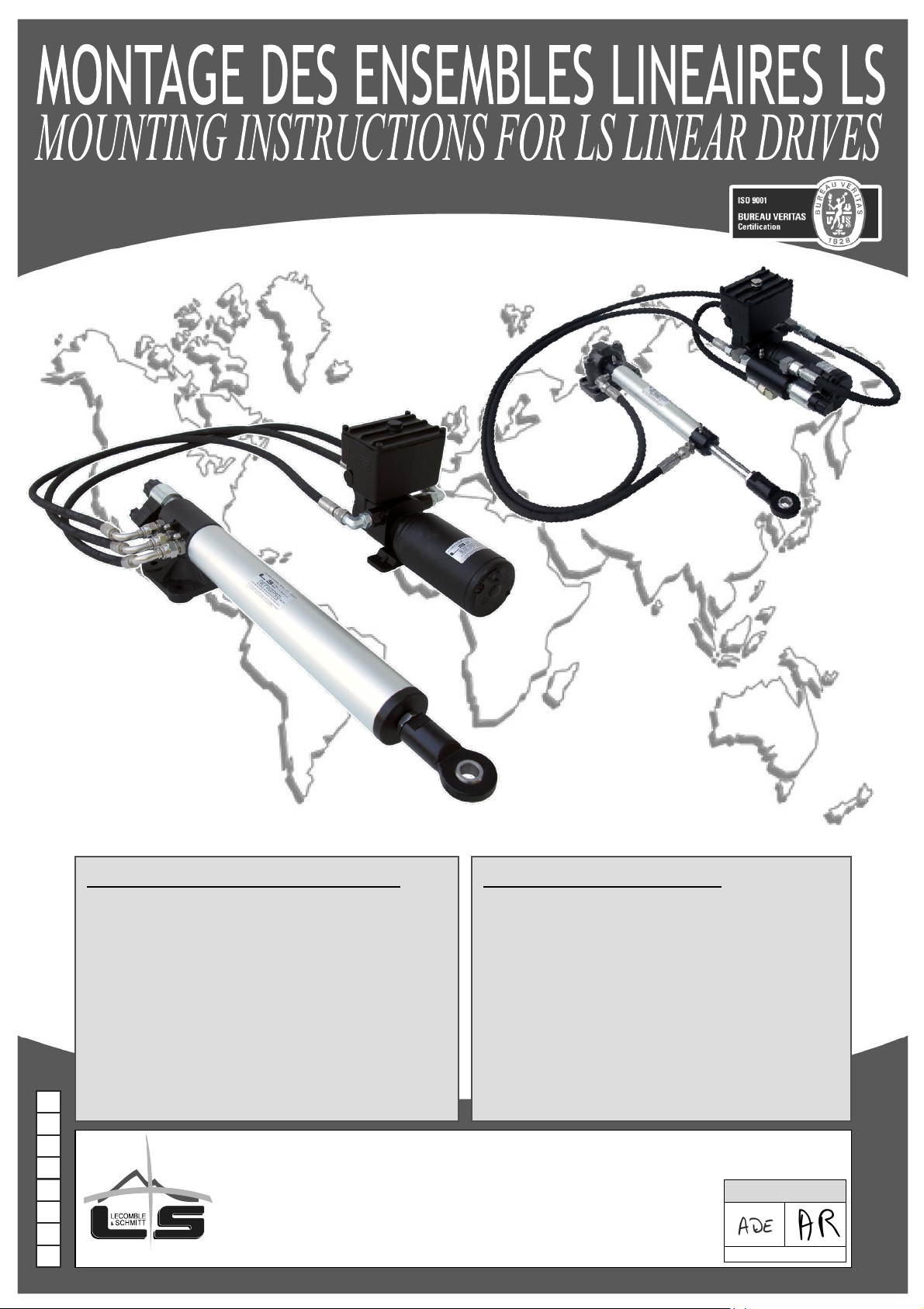
Outillage nécessaire pour l’installation
- 1 jeu de clés plates : 7 à 32
- 1 clé à molette
- 1 jeu de tournevis plats
- 1 jeu de clés mâles 6 pans
- 1 cutter
- 1 perceuse + 1 jeu de forets
- 1 paire de tenaille
- 1 clé dynamométrique
Tools required for the installation
- 1 set of spanners: 7 to 32
- 1 adjustable spanner
- 1 set of straight screwdrivers
- 1 set of hexagon keys
- 1 cutter
- 1 drilling machine + 1 set of drill bits
- 1 pair of pliers
- 1 torque wrench
I
1
0
4
-
T
O
N
S.A.S
LECOMBLE & SCHMITT
156 Route de Briscous - 64240 URT - FRANCE
T
+
33(0)559 562 646 -
v +
33(0)559 569 571
Validé par / Approved by
Date : 04-05-2021
Page 2
MONTAGE DES ENSEMBLES LINEAIRES LS
MOUNTING INSTRUCTIONS FOR LS LINEAR DRIVES
SOMMAIRE Page
CONTENTS Page
Recommandations importantes ..................................................... 2
Instructions de montage
Ensembles linéaires hydrauliques – Montage intérieur
32 ST 16 – 40 ST 16 – 50 ST 20 – 50 ST 203 ................... 3 à 4
63 ST 28 ............................................................................. 5 à 6
Ensembles linéaires hydrauliques – Montage extérieur
28 DTP RV07 BP ............................................................... 7 à 8
32 ST 16 BP – 40 T 254 BP ............................................. 9 à 10
Schémas de câblage électriques pour
32 ST 16 – 40 ST 16 – 50 ST 20 – 50 ST 203 – 63 ST 28
28 DTP RV07 – 32 ST 16 BP – 40 T 254 BP ........................ 11
Purge du circuit :
Ensembles linéaires hydrauliques - Montage extérieur ... 12
Important Recommendations .................................................................... 2
Mounting Instructions
Hydraulic Linear Drives – Internal Installation
32 ST 16 – 40 ST 16 – 50 ST 20 – 50 ST 203 .............................. 3 to 4
63 ST 28 ........................................................................................ 5 to 6
Hydraulic Linear Drives – External Installation
28 DTP RV07 BP ......................................................................... 7 to 8
32 ST 16 BP – 40 T 254 BP ....................................................... 9 to 10
Electric Connection Drawing for
32 ST 16 – 40 ST 16 – 50 ST 20 – 50 ST 203 – 63 ST 28
28 DTP RV07 – 32 ST 16 BP – 40 T 254 BP ................................... 11
Bleeding of the Circuit:
Hydraulic Linear Drives – External Installation ............................ 12
Page 3
RECOMMANDATIONS IMPORTANTES
IMPORTANT RECOMMENDATIONS
! Toutes les cotes indiquées sont exprimées en millimètre.
! All dimensions are quoted in mm.
• Power pack units should be:
- installed by a qualified person with the required competency.
- located in a well ventilated environment, allowing easy access to all
the unit components
• Check that the supply voltage on the boat matches the one on the
power pack assembly (motor, electro-valve, etc.) and that the wiring
section is correctly sized in function of your installation.
• The power pack assembly and more particularly the cylinder rod
should be protected against risks of impacts, scratches or other
damages during the installation.
• No impurities are to enter the components of the power pack assembly.
Hydraulic hoses, hydraulic piping and fittings should be cleaned prior
to connection.
• No foreign body should hinder the linear cylinder operation (electrical
cables, tubing, earth connection braiding, rigid objects, etc.).
Make sure that the cylinder can move freely and that the bleeder cocks
are accessible, whatever way the cylinder has been installed (ceiling,
floor or bulkhead mounted).
• The mounting areas for the cylinder support plate and the power pack
mounting brackets must be perfectly even and free of foreign bodies.
• The electro-pump must be positioned as close as possible to the boat
lubber line,away from possible water projections.
• The screws and bolts to fix the linear cylinder must be selected in
function of the hole diameters K and F in the support plate and the
swivel yoke (see the dimension table for your cylinder). Strictly follow
the torque indications ( … Nm).
• Grease the ball swivel of the swivel yoke on a regular basis
(cylinder/tiller arm connection).
• When bleeding the system, make sure that no impurity enters the
circuit.
• L'ensemble groupe de pilotage doit :
- être installé par une personne ayant toutes les compétences
requises.
- être installé dans un environnement bien ventilé, permettant l'accès
aux éléments qui le composent.
• Vérifier que la tension d'alimentation correspond à celle des organes de
l'ensemble groupe de pilotage (moteur, électrovanne, etc.) et que la
section de câblage soit dimensionnée en fonction de votre installation.
• Pendant toute la durée d’installation, protéger l'ensemble groupe de
pilotage, et plus particulièrement la tige du vérin contre tout risque
de choc, de rayure ou de tout autre type de dégradation.
• Aucune impureté ne doit pénétrer à l’intérieur de l'ensemble groupe
de pilotage. Les flexibles, la tuyauterie et les raccords doivent être
nettoyés avant tout raccordement.
• Aucun élément étranger ne doit entraver le bon fonctionnement du
vérin linéaire (câblage électrique, tuyaux, tresses de masse, objets
rigides, etc.).
S’assurer que le vérin reste libre dans tous ses déplacements et
que, quel que soit le montage (plancher, plafond, cloison), les
purgeurs soient accessibles.
• La surface d'appui des paliers ou pattes de fixation groupe et vérin
doivent être parfaitement planes, sans corps étrangers.
• Le groupe électro-pompe doit être placé au plus près de la ligne de
foi du bateau et à l’abri de toutes projections d’eau.
• La visserie de fixation du vérin linéaire doit être choisie en fonction
des diamètres K et F des trous de fixation des paliers et de la chape
(Voir tableau des cotes correspondant à votre vérin). Il est impératif
de respecter les couples de serrage indiqués ( … Nm).
• Graisser périodiquement les rotules des chapes (liaison
vérin/bras de mèche).
• En cas d’opération de purge, veiller à ce qu’aucune impureté n’entre
dans le circuit.
2
Page 4
ENSEMBLES LINEAIRES HYDRAULIQUES – MONTAGE INTERIEUR
HYDRAULIC LINEAR DRIVES – INTERNAL INSTALLATION
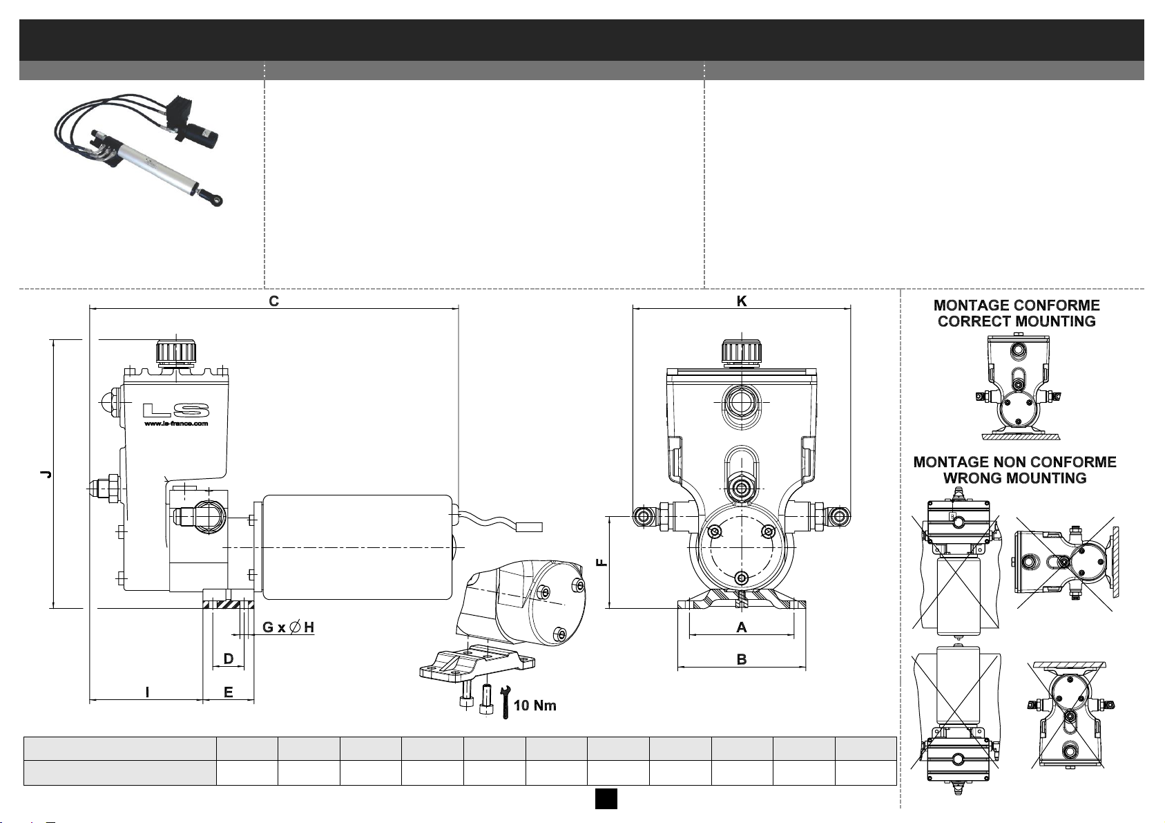
Instructions de montage côté GROUPE
Mounting instructions of POWER PACK UNIT
Ensembles linéaires
Linear drives
32 ST 16 – 40 ST 16
50 ST 20 – 50 ST 203
! Ne pas ouvrir le circuit hydraulique (raccords, purgeurs…).
Ces ensembles sont livrés pré-remplis et purgés.
Avant la mise en route, remplacer le bouchon étanche par le
bouchon clapet livré avec l'ensemble linéaire.
1. Positionner et fixer le groupe RV1 ST, RV2 ST ou RV3 ST à
l'emplacement choisi selon notre paragraphe
"Recommandations importantes". En fonction de
l'emplacement choisi, veillez à respecter un rayon de
courbure minimum des flexibles de 90 mm.
2. Procéder au branchement électrique selon notre paragraphe
"Schéma de câblage électrique".
! Do not open the hydraulic circuit (fittings, bleeder cocks…). The
drives are supplied filled with oil and bled.
Before putting the unit into service, replace the non vented plug by
the flap plug supplied with the linear drive.
1. Position and secure power pack RV1 ST, RV2 ST or RV3 ST at the
selected location as per our paragraph “Important
recommendations”. Observe a minimum bending radius of the
flexible pipes of 90 mm.
2. Proceed with the electric connections by following the
recommendations in paragraph “electric connection drawing”.
A B C D E F G
Ø H I J
K
RV1 ST / RV2 ST / RV3 ST
80
98
290
24
39
70 4 6,5
90
206
168
3
Page 5
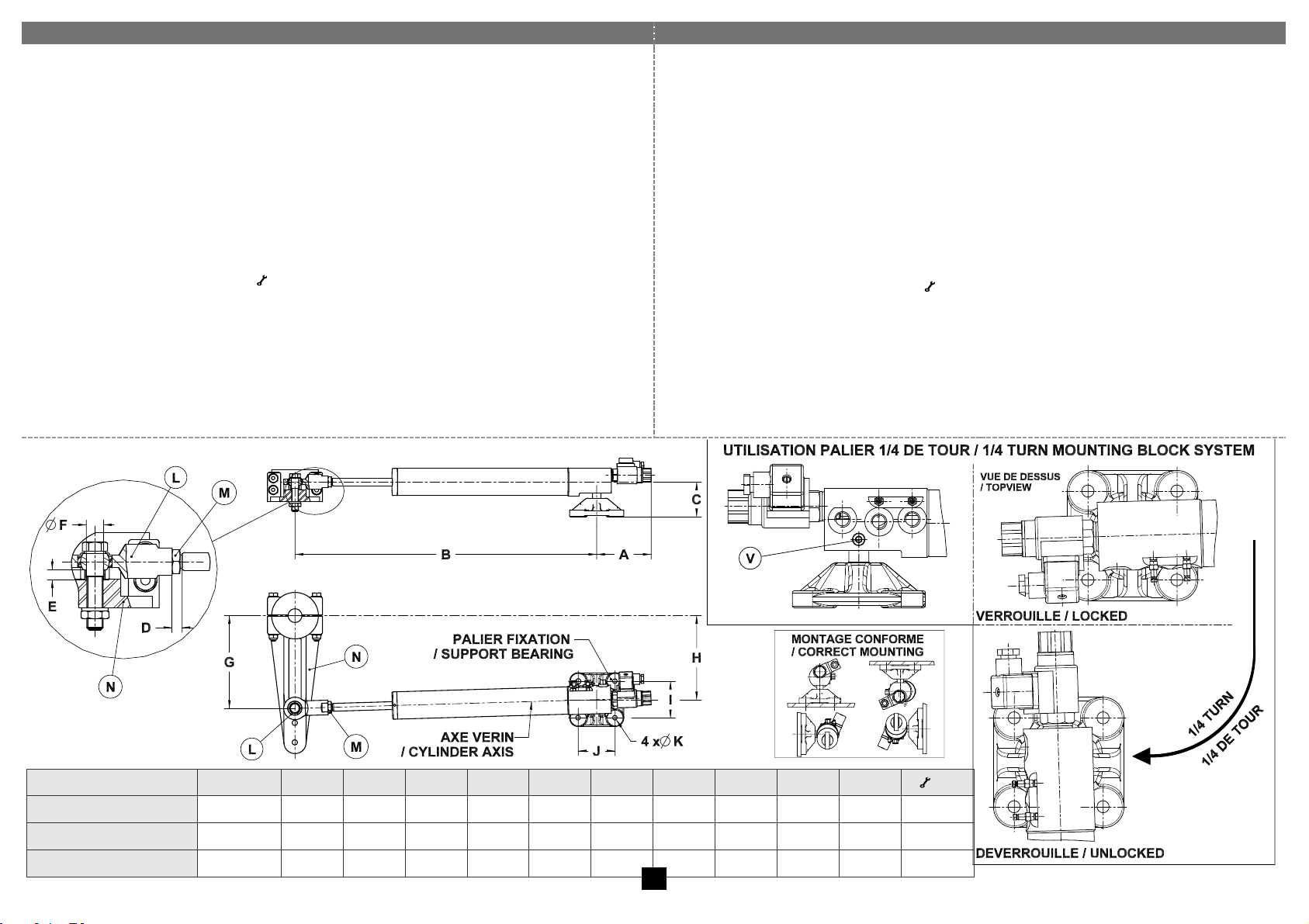
Instructions de montage côté VERIN
Mounting instructions for the CYLINDER
! Ne pas ouvrir le circuit hydraulique (raccords, flexibles). Ces ensembles sont
livrés pré-remplis et purgés.
Pour désaccoupler et utiliser la fonction palier ¼ de tour, retirer la vis V.
A chaque montage du vérin sur son palier, s’assurer que le palier est verrouillé
(1/4 de tour) et que la vis V est en place.
3. Positionner le bras de mèche N (ou le safran) à 0° (navigation en ligne droite).
4. Régler la tige à mi-course (cote B) en respectant impérativement les cotes G et
H. Ce réglage permet d'obtenir 70° (2 x 35°) de battement du safran. En
fonction de l'emplacement choisi, veillez à respecter un rayon de courbure
minimum des flexibles de 90 mm.
5. Régler la chape à rotule L en respectant la cote D. Bloquer l'écrou chape M
contre la chape à rotule L ( Nm : voir tableau).
6. Nous recommandons de positionner la chape à rotule L du vérin sur la face
supérieure du bras de mèche N (ou du secteur) en respectant impérativement
la cote E à l'aide d'une entretoise.
7. Solidariser le vérin au bras de mèche N (ou au secteur) et au bateau avec les
visseries appropriées, puis les bloquer.
8. Procéder au branchement électrique selon notre paragraphe "Schéma de
câblage électrique".
! Do not open the hydraulic circuit (fittings, flexible tubes…). The drives are supplied
filled with oil and bled.
To disconnect the cylinder by using the ¼ turn function on the mounting block, remove screw V.
When mounting the cylinder on its mounting block, make sure that the mounting block
is locked (1/4 turn) and that screw V is tight.
3. Position the tiller arm N (or the rudder) at 0° (navigation straight ahead)
4. Position the cylinder at half stroke (dimension B) and follow the dimensions G and H
strictly. This configuration is necessary to obtain 70° (2 x 35°) total rudder angle. In
function of the selected location for the installation, please note that the minimum
bending radius of the flexible pipes is 90 mm.
5. Adjust swivel yoke L by ensuring that dimension D is accurate. Lock the swivel yoke
nut M against the swivel yoke L ( Nm : see torque chart).
6. We recommend that swivel yoke L is positioned above tiller arm N (or quadrant).
Ensure that dimension E is strictly observed by inserting a spacer.
7. Connect the cylinder to the tiller arm N (or to the quadrant). Fix the cylinder on the
boat by using appropriate nuts and bolts. Tighten all nuts and bolts.
8. Proceed with the electric connection by following the recommendations in paragraph
“electric connection drawing”.
A B C D E
Ø F G H I J
Ø K
( Nm)
VHM 32 ST 16 DE BP
111
563
71 9 9
15
170
160
75
75
11
36,3
VHM 40 ST 16 DE BP
111
613
71 9 9
15
190
172
75
75
11
36,3
VHM 50 ST 20 DE BP
111
715
76 8 9
17
240
218
75
75
11
55,89
4
Page 6
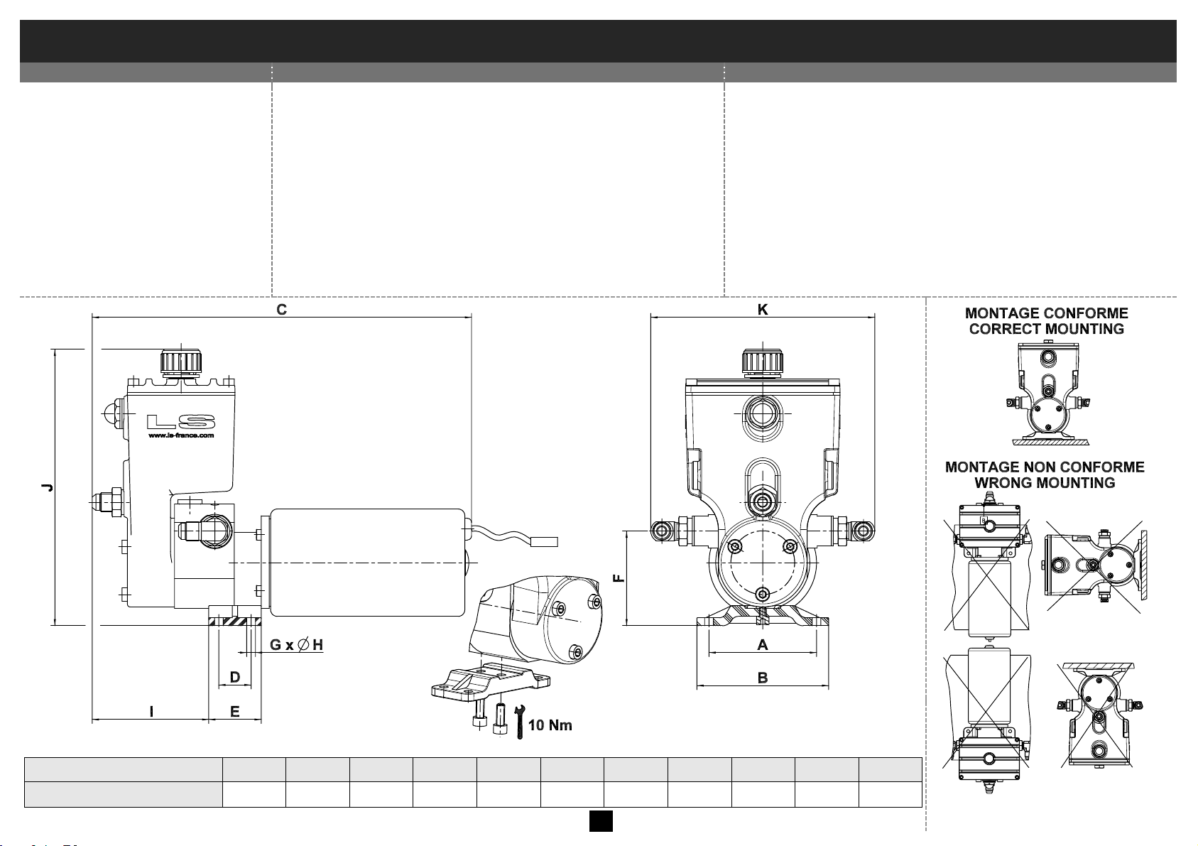
ENSEMBLES LINEAIRES HYDRAULIQUES – MONTAGE INTERIEUR
HYDRAULIC LINEAR DRIVES – INTERNAL INSTALLATION
Instructions de montage côté GROUPE
Mounting instructions of POWER PACK UNIT
Ensembles linéaires
Linear drives
63 ST 28
! Ne pas ouvrir le circuit hydraulique (raccords, purgeurs…).
Ces ensembles sont livrés pré-remplis et purgés.
Avant la mise en route, remplacer le bouchon étanche par le
bouchon clapet livré avec l'ensemble linéaire.
1. Positionner et fixer le groupe RV3 ST à l'emplacement choisi
selon notre paragraphe "Recommandations importantes".
En fonction de l'emplacement choisi, veillez à respecter un
rayon de courbure minimum des flexibles de 90 mm.
2. Procéder au branchement électrique selon notre paragraphe
"Schéma de câblage électrique".
! Do not open the hydraulic circuit (fittings, bleeder cocks…). The
drives are supplied filled with oil and bled.
Before putting the unit into service, replace the non vented plug by
the flap plug supplied with the linear drive.
1. Position and secure power pack RV3 ST at the selected location as
per our paragraph “Important recommendations”. Observe a
minimum bending radius of the flexible pipes of 90 mm.
2. Proceed with the electric connections by following the
recommendations in paragraph “electric connection drawing”.
A B C D E F G
Ø H I J
K
RV3 ST
80
98
290
24
39
70 4 6,5
90
206
168
5
Page 7
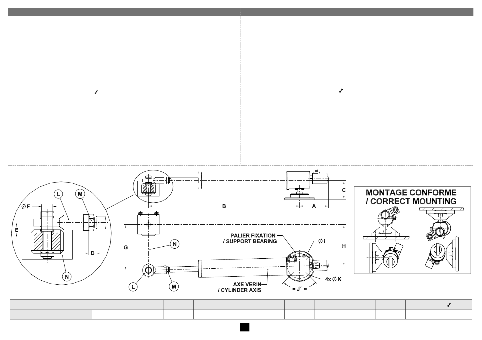
Instructions de montage côté VERIN
Mounting instructions for the CYLINDER
! Ne pas ouvrir le circuit hydraulique (raccords, flexibles). Ces ensembles sont
livrés pré-remplis et purgés.
3. Positionner le bras de mèche N (ou le safran) à 0° (navigation en ligne droite).
4. Régler la tige à mi-course (cote B) en respectant impérativement les cotes G et
H. Ce réglage permet d'obtenir 70° (2 x 35°) de battement du safran. En
fonction de l'emplacement choisi, veillez à respecter un rayon de courbure
minimum des flexibles de 90 mm.
5. Régler la chape à rotule L en respectant la cote D. Bloquer l'écrou chape M
contre la chape à rotule L ( Nm : voir tableau).
6. Nous recommandons de positionner la chape à rotule L du vérin sur la face
supérieure du bras de mèche N (ou du secteur) en respectant impérativement
la cote E à l'aide d'une entretoise.
7. Solidariser le vérin au bras de mèche N (ou au secteur) et au bateau avec les
visseries appropriées, puis les bloquer.
8. Procéder au branchement électrique selon notre paragraphe "Schéma de
câblage électrique".
! Do not open the hydraulic circuit (fittings, flexible tubes…). The drives are supplied
filled with oil and bled.
3. Position the tiller arm N (or the rudder) at 0° (navigation straight ahead)
4. Position the cylinder at half stroke (dimension B) and follow the dimensions G and H
strictly. This configuration is necessary to obtain 70° (2 x 35°) total rudder angle. In
function of the selected location for the installation, please note that the minimum
bending radius of the flexible pipes is 90 mm.
5. Adjust swivel yoke L by ensuring that dimension D is accurate. Lock the swivel yoke
nut M against the swivel yoke L ( Nm : see torque chart).
6. We recommend that swivel yoke L is positioned above tiller arm N (or quadrant).
Ensure that dimension E is strictly observed by inserting a spacer.
7. Connect the cylinder to the tiller arm N (or to the quadrant). Fix the cylinder on the
boat by using appropriate nuts and bolts. Tighten all nuts and bolts.
8. Proceed with the electric connection by following the recommendations in paragraph
“electric connection drawing”.
A B C D E
Ø F G H
ØI
J°
Ø K
( Nm)
VHM 63 ST 28 DE BP
152
802
100
17
13
25
240
218
130
90
12.5
188
6
Page 8
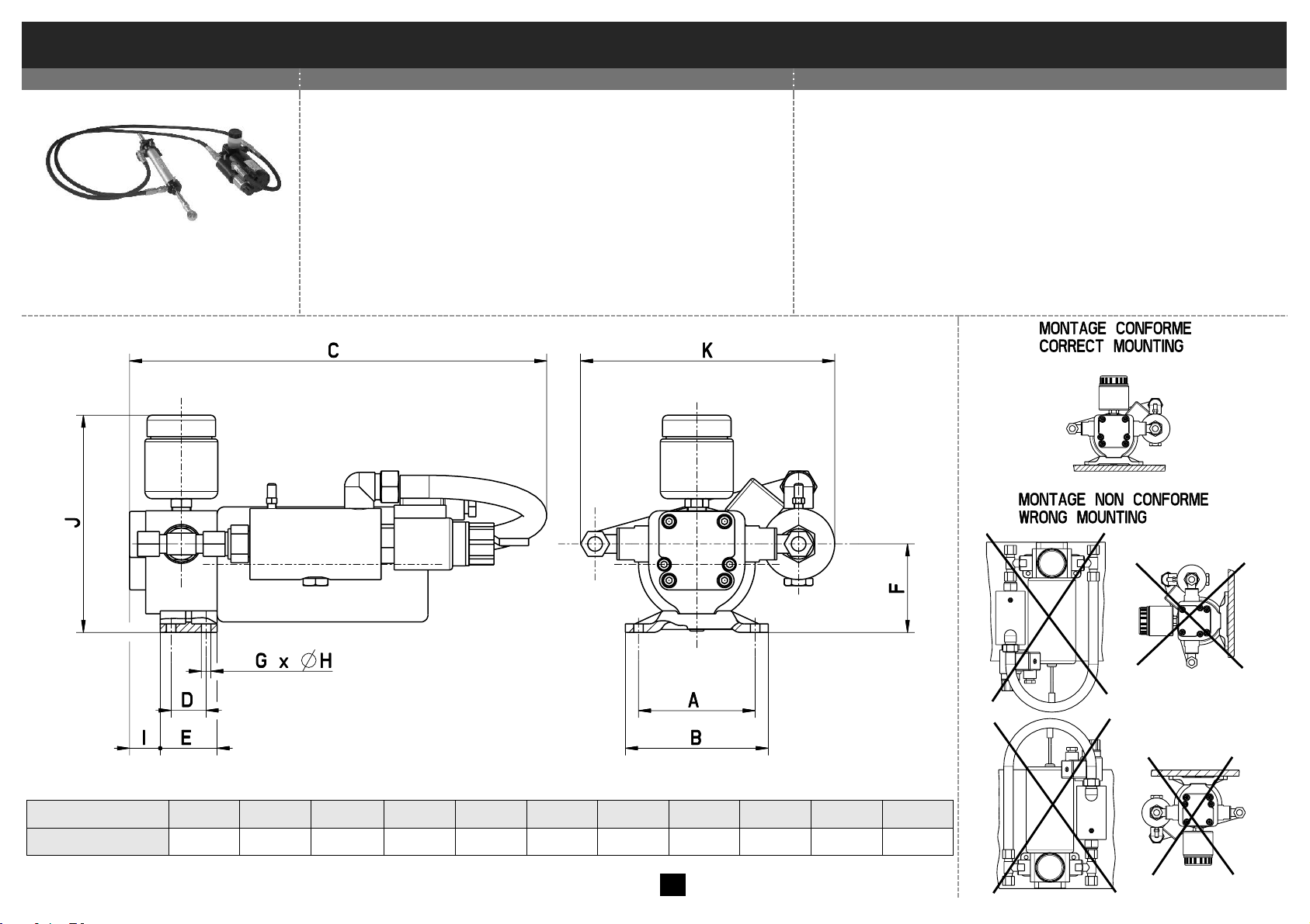
ENSEMBLES LINEAIRES HYDRAULIQUES – MONTAGE EXTERIEUR
HYDRAULIC LINEAR DRIVES – EXTERNAL INSTALLATION
Instructions de montage côté GROUPE
Mounting instructions for the POWER PACK UNIT
Ensembles linéaires
Linear drives
28 DTP RV07 BP
! Ne pas ouvrir le circuit hydraulique (raccords, purgeurs…).
Ces ensembles sont livrés pré-remplis et purgés.
1. Positionner et fixer le groupe RV07 ST à l'emplacement choisi
selon notre paragraphe "Recommandations importantes".
En fonction de l'emplacement choisi, veillez à respecter un
rayon de courbure minimum des flexibles de 90 mm.
2. Procéder au branchement électrique selon notre paragraphe
"Schéma de câblage électrique".
! Do not open the hydraulic circuit (fittings, bleeder cocks…).
The drives are supplied filled with oil and bled.
1. Position and secure power pack RV 07 ST at the selected location
as per our paragraph “Important recommendations”. Observe a
minimum bending radius of the flexible pipes of 90 mm.
2. Proceed with the electric connections by following the
recommendations in paragraph “electric connection drawing”.
A B C D E F G
Ø H I J K RV07 ST
80
98
280±10
24
39
65 4 6,5
21
150±5
177±5
7
Page 9
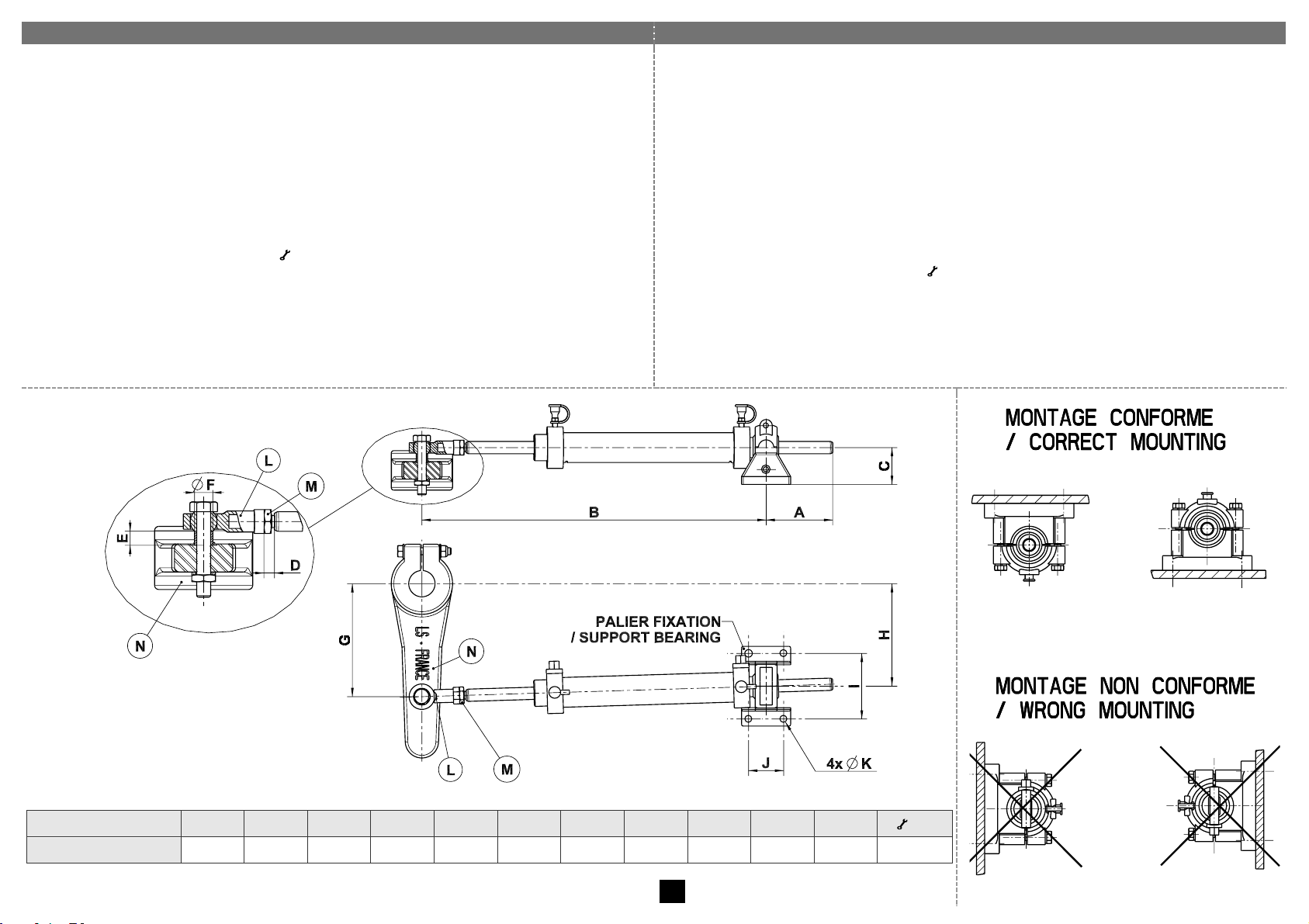
Instructions de montage côté VERIN
Mounting instructions for the CYLINDER
! Ne pas ouvrir le circuit hydraulique (raccords, flexibles). Ces ensembles sont
livrés pré-remplis et purgés. Si l’installation nécessite le démontage des
flexibles (côté vérin), se reporter au paragraphe « purge du circuit » page 12.
3. Positionner le bras de mèche N (ou le safran) à 0° (navigation en ligne droite).
4. Présenter le vérin, tige réglée à mi-course (cote B) en respectant
impérativement les cotes G et H. Ce réglage permet d'obtenir 70° (2 x 35°) de
battement du safran. En fonction de l'emplacement choisi, veillez à respecter
un rayon de courbure minimum des flexibles de 90 mm.
5. Régler la chape à rotule L en respectant la cote D. Bloquer l'écrou de chape
M contre la chape à rotule L ( Nm : voir tableau).
6. Nous recommandons de positionner la chape à rotule L du vérin sur la face
supérieure du bras de mèche N (ou du secteur) en respectant impérativement
la cote E à l'aide d'une entretoise.
7. Solidariser le vérin au bras de mèche N (ou au secteur) et au bateau avec les
visseries appropriées, puis les bloquer.
! Do not open the hydraulic circuit (fittings, flexible tubes…). The drives are supplied
filled with oil and bled. If the installation requires the dismantling of the flexible tubes
(on the cylinder side), please refer to paragraph « Bleeding of the Circuit » on page 12.
3. Position the tiller arm N (or the rudder) at 0° (navigation straight ahead)
4. Position the cylinder at half stroke (dimension B) and follow the dimensions G and H
strictly. This configuration is necessary to obtain 70° (2 x 35°) total rudder angle. In
function of the selected location for the installation, please note that the minimum
bending radius of the flexible pipes is 90 mm.
5. Adjust swivel yoke L by ensuring that dimension D is observed. Lock the swivel yoke
nut M against the swivel yoke L ( Nm : see torque chart).
6. We recommend to position swivel yoke L above the tiller arm N (or quadrant).
Ensure that dimension E is strictly observed by inserting a spacer.
7. Connect the cylinder to the tiller arm N (or to the quadrant). Fix the cylinder on the
boat by using appropriate nuts and bolts. Tighten all nuts and bolts.
A B C D E
Ø F G H I J
Ø K
( Nm)
VHM 28 DTP
76
393
42
10
10
10
129
117
75
40
8,5
13,40
8
Page 10
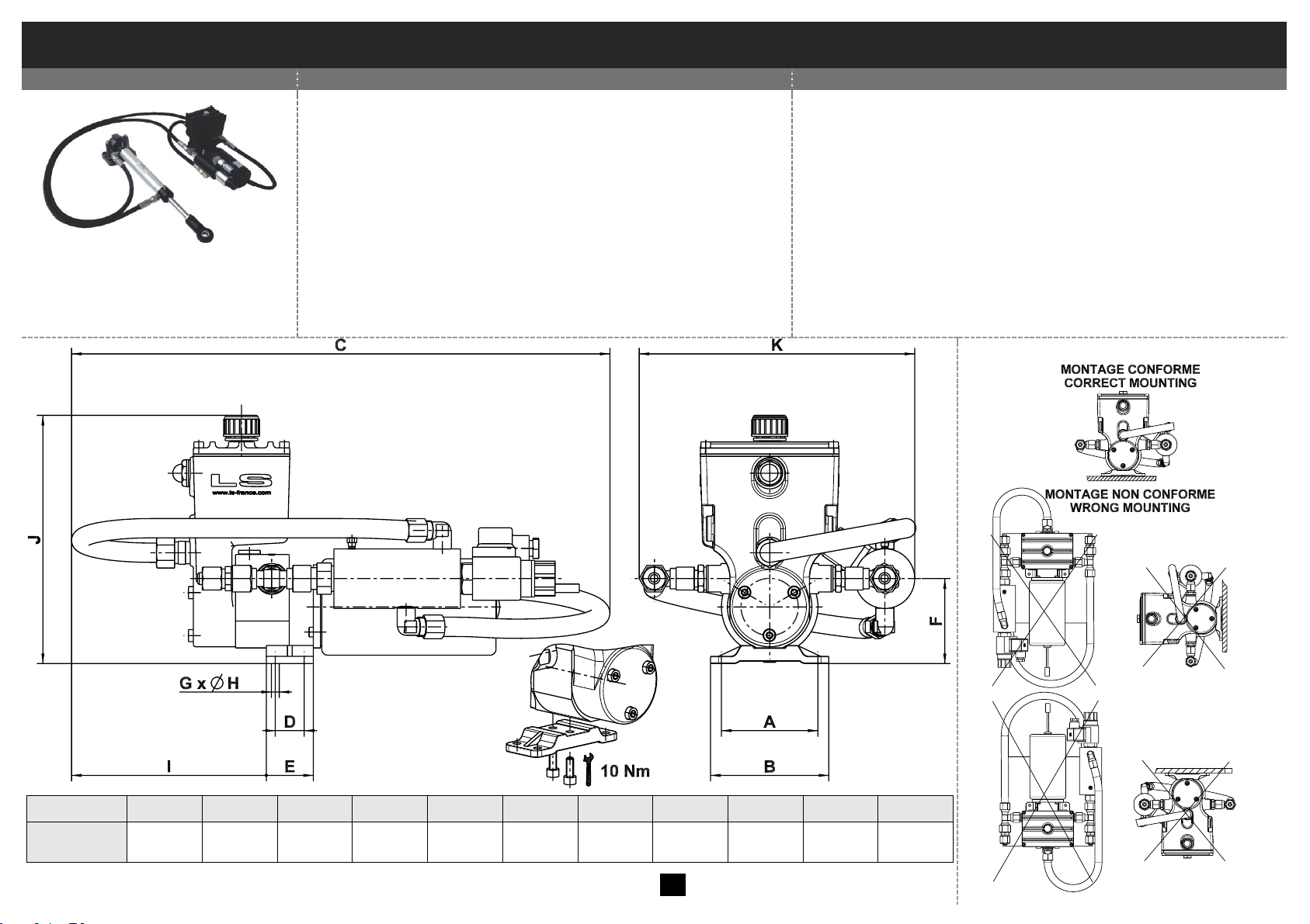
ENSEMBLES LINEAIRES HYDRAULIQUES – MONTAGE EXTERIEUR
HYDRAULIC LINEAR DRIVES – EXTERNAL INSTALLATION
Instructions de montage côté GROUPE
Mounting instructions for the POWER PACK UNIT
Ensemble linéaire
Linear drive
32 ST16 BP - 40 T 254 BP
! Ne pas ouvrir le circuit hydraulique (raccords, purgeurs…).
Ces ensembles sont livrés pré-remplis et purgés.
Avant la mise en route, remplacer le bouchon étanche par le
bouchon clapet livré avec l'ensemble linéaire.
1. Positionner et fixer le groupe RV1 BP ou RV2 BP à
l'emplacement choisi selon notre paragraphe
"Recommandations importantes". En fonction de
l'emplacement choisi, veillez à respecter un rayon de
courbure minimum des flexibles de 90 mm.
2. Procéder au branchement électrique selon notre paragraphe
"Schéma de câblage électrique".
! Do not open the hydraulic circuit (fittings, bleeder cocks…). The
drives are supplied filled with oil and bled.
Before putting the unit into service, replace the non vented plug by
the flap plug supplied with the linear drive.
1. Position and secure power pack RV1 BP or RV2 BP at the
selected location as per our paragraph “Important
recommendations”. Observe a minimum bending radius of the
flexible pipes of 90 mm.
2. Proceed with the electric connections by following the
recommendations in paragraph “electric connection drawing”.
A B C D E F G Ø H I J
K
RV1 BP
RV2 BP
80
98
450
24
39
70,5 4 6,5
160
206
230
9
Page 11
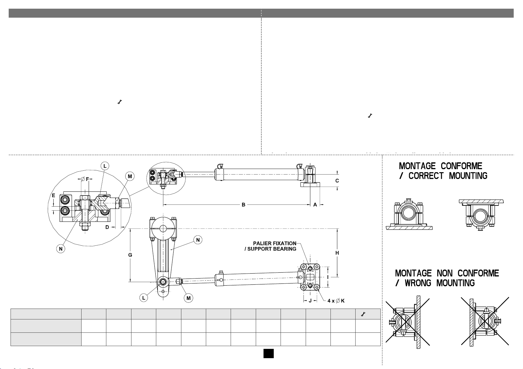
Instructions de montage côté VERIN
Mounting instructions for the CYLINDER
! Ne pas ouvrir le circuit hydraulique (raccords, flexibles). Ces ensembles
sont livrés pré-remplis et purgés. Si l’installation nécessite le démontage des
flexibles (côté vérin), se reporter au paragraphe « purge du circuit » page 12.
3. Positionner le bras de mèche N (ou le safran) à 0° (navigation en ligne droite).
4. Présenter le vérin, tige réglée à mi-course (cote B) en respectant
impérativement les cotes G et H. Ce réglage permet d'obtenir 70° (2 x 35°) de
battement du safran. En fonction de l'emplacement choisi, veillez à respecter
un rayon de courbure minimum des flexibles de 90 mm.
5. Régler la chape à rotule L en respectant la cote D. Bloquer l'écrou de chape
M contre la chape à rotule L ( Nm : voir tableau).
6. Nous recommandons de positionner la chape à rotule L du vérin sur la face
supérieure du bras de mèche N (ou du secteur) en respectant impérativement
la cote E à l'aide d'une entretoise.
7. Solidariser le vérin au bras de mèche N (ou au secteur) et au bateau avec les
visseries appropriées, puis les bloquer.
! Do not open the hydraulic circuit (fittings, flexible tubes…). The drives are
supplied filled with oil and bled. If the installation requires the dismantling of the
flexible tubes (on the cylinder side), please refer to paragraph « Bleeding of the
Circuit » on page 12.
3. Position the tiller arm N (or the rudder) at 0° (navigation straight ahead)
4. Position the cylinder at half stroke (dimension B) and follow the dimensions G and H
strictly. This configuration is necessary to obtain 70° (2 x 35°) total rudder angle. In
function of the selected location for the installation, please note that the minimum
bending radius of the flexible pipes is 90 mm.
5. Adjust swivel yoke L by ensuring that dimension D is observed. Lock the swivel yoke
nut M against the swivel yoke L ( Nm : see torque chart).
6. We recommend to position swivel yoke L above the tiller arm N (or quadrant).
Ensure that dimension E is strictly observed by using a spacer.
7. Connect the cylinder to the tiller arm N (or to the quadrant). Fix the cylinder on the
A B C D E
Ø F G H I J
Ø K
( Nm)
VHM 32 ST 16 C172
40
482
51 8 9
15
150
136.5
85
55
11
36,30
VHM 40 T C254
40
609
51
12 9 17
220
200
85
55
11
55,89
10
Page 12
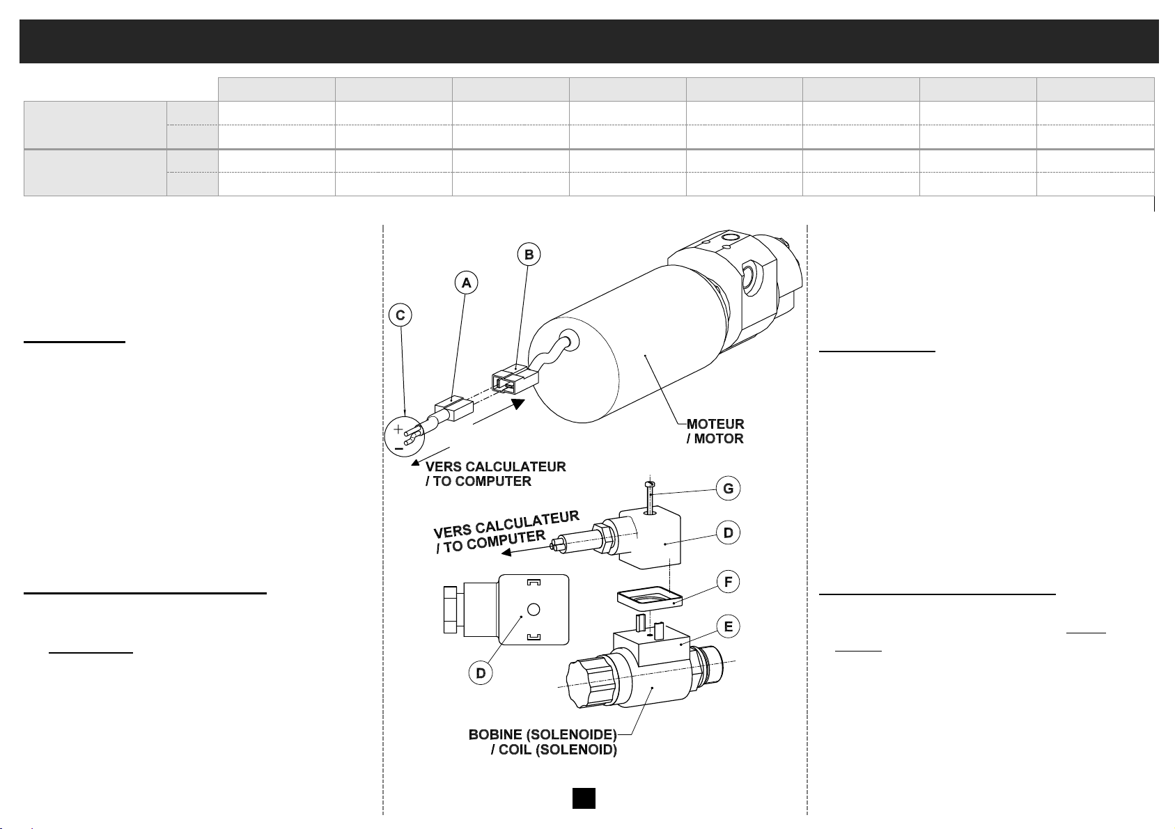
SCHÉMA DE CÂBLAGE ÉLECTRIQUE POUR 32ST16 – 40ST16 – 50ST20 – 50ST203 – 63ST28 – 28DTPRV07 – 32ST16BP – 40T254BP
ELECTRIC CONNECTION DRAWING FOR 32ST16 – 40ST16 – 50ST20 – 50ST203 – 63ST28 – 28DTPRV07 – 32ST16BP – 40T254BP
32 ST 16
40 ST 16
50 ST 20
50 ST 203
63 ST 28
28 DTP RV07
32 ST 16 BP
40 T 254 BP
Protection conseillée
Recommended
protection
12 V
16 A
25 A
25 A
30 A
30 A
16 A
16 A
25 A
24 V
6 A
16 A
16 A
16 A
16 A
6 A
6 A
16 A
Section fil (*)
Wire Cross Section (*)
12 V
4 mm2 / sq.mm
6 mm2 / sq.mm
6 mm2 / sq.mm
10 mm2 / sq.mm
10 mm2 / sq.mm
4 mm2 / sq.mm
4 mm2 / sq.mm
6 mm2 / sq.mm
24 V
2,5 mm2 / sq.mm
4 mm2 / sq.mm
4 mm2 / sq.mm
4 mm2 / sq.mm
4 mm2 / sq.mm
2,5 mm2 / sq.mm
2,5 mm2 / sq.mm
4 mm2 / sq.mm
(*) longueur maxi : 5 mètres / maximum length : 5 meters
! Toutes les opérations décrites ci-dessous
doivent s’effectuer en ayant pris soin de couper
l’alimentation électrique. S’assurer que la
tension d’alimentation (12 ou 24 V) correspond
à la tension indiquée sur le moteur.
Partie : moteur
1. Connecter la ½ prise A fournie avec le groupe
sur les fils d’alimentation électrique C.
2. Connecter les ½ prises A et B sans tenir
compte des polarités + et –
3. Mettre le circuit électrique sous tension.
4. Procéder à la mise en route du pilote selon les
instructions de son fabricant.
5. Si le moteur du groupe tourne dans le mauvais
sens (déplacement du vérin contraire à celui
demandé), inverser les polarités + et – dans la
½ prise A.
Partie : bypass / bobine (solénoïde)
1. Branchez une extrémité du câble préconisé par
le fabricant du calculateur sur la prise femelle D
(Alimentation : bornes en U, aucune polarité à
respecter). Raccorder l’autre extrémité du câble
sur le calculateur.
2. Positionner la prise femelle D sur la prise mâle
E en veillant à bien positionner le joint
d’étanchéité F. Bloquer l’ensemble à l’aide de
la vis G.
!
All the electrical connections below must
be carried out once the electrical supply has
been cut off. Check that the supply voltage
(12 or 24 V) is the same as the one specified
on the motor.
Motor Connection
1. Connect the “half plug” A supplied with the
power pack to the electric wires C.
2. Fit together both “half-plugs” A and B without
taking into account the + and – polarities.
3. Turn the power on.
4. Put the autopilot electronics into service as per
the manufacturer’s instructions.
5. If the power pack motor turns the wrong way round
(motion of the cylinder in the wrong direction), simply
inverse + and – polarities in the “half-plug” A.
By-Pass Valve (Solenoid) Connection
1. Connect the cable preconised by the electronics
manufacturer to the female plug D. (Power
Supply: U-shaped terminals, irrespective of
polarity). Connect the other wire end to the
autopilot computer.
2. Fit together Female plug D on male plug E.
Make sure that seal F is correctly positioned.
Secure the assembly with screw G.
11
Page 13
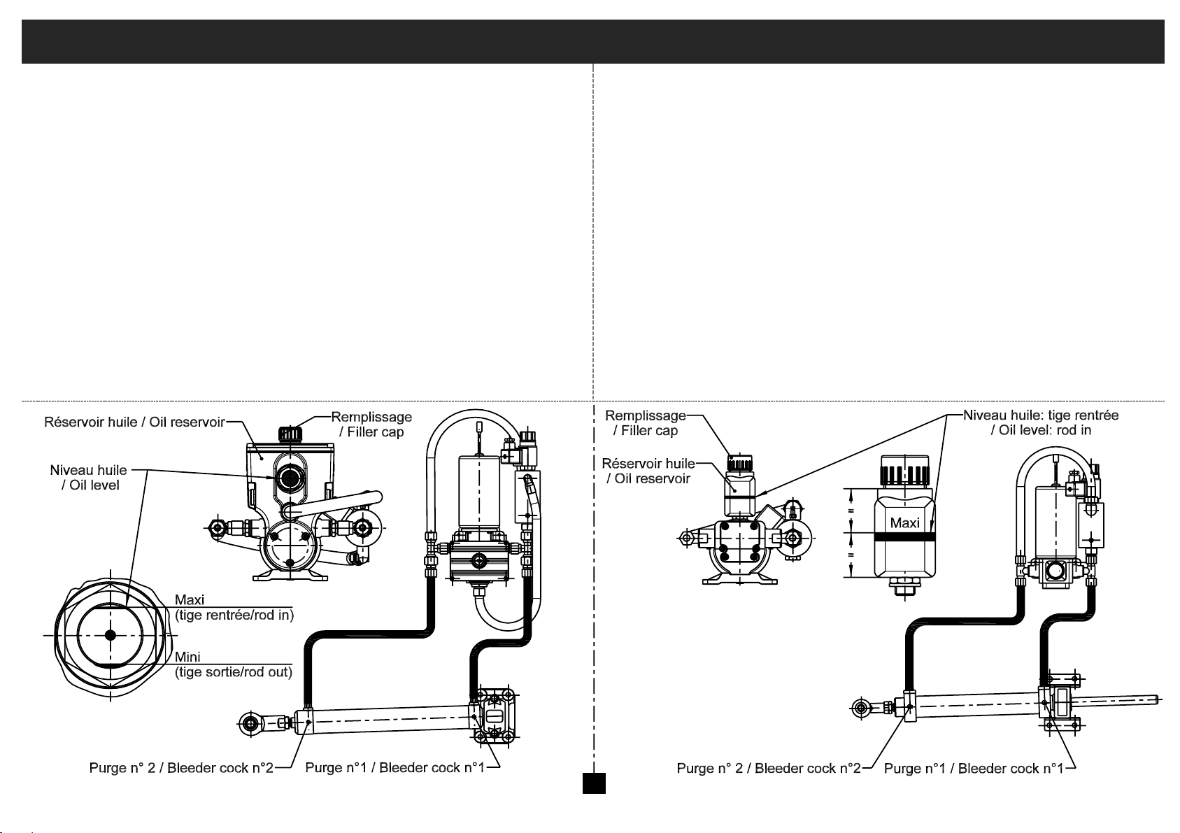
PURGE DU CIRCUIT: ENSEMBLES LINEAIRES HYDRAULIQUES – MONTAGE EXTERIEUR
BLEEDING OF THE CIRCUIT: HYDRAULIC LINEAR DRIVES – EXTERNAL INSTALLATION
! Cette partie concerne uniquement les ensembles linéaires montage
extérieur dont les flexibles ont été démontés.
Le réservoir d’huile devra être constamment rempli d’huile pendant
toute l’opération de purge (huile LS ou de viscosité ISO 22).
1. Désaccoupler le vérin du bras de mèche ou du secteur et le mettre en position
« tige rentrée » (voir schémas).
2. Ouvrir la purge n°1.
3. Exciter l’électrovanne.
4. Faire tourner le groupe dans le bon sens de façon à ce que l’huile sorte par la
purge n°1 et que la tige du vérin sorte totalement jusqu’au bout de sa course.
5. Le groupe continue à tourner : lorsque l’huile sort sans air, arrêter le groupe.
6. Fermer la purge n°1 (" 3,5 Nm).
7. Ouvrir la purge n°2.
8. Faire tourner le groupe en sens inverse ; lorsque la tige est rentrée et que
l’huile sort sans air de la purge n°2, fermer la purge n°2 (" 3,5 Nm).
9. Faire le niveau d’huile au niveau maxi, tige rentrée (voir schémas).
! This part only concerns linear drives for external installation of the cylinder when
the flexible tubes had to be dismantled.
The oil reservoir must be kept full of oil during the complete bleeding procedure
(LS oil or oil with ISO22 viscosity grade).
1. Disconnect the cylinder from the quadrant or tiller arm and retract the rod fully inside
the cylinder tube (see drawings).
2. Open bleeder cock n°1.
3. Energise the electro-valve.
4. Run the power pack in the correct direction so that the oil is pushed out through
bleeder cock n° 1 and until the cylinder rod is fully extended).
5. Let the power pack run until the oil coming out is free of air bubbles.Then turn the
power pack off.
6. Close bleeder cock n°1 (" 3,5 Nm).
7. Open bleeder cock n°2.
8. Run the power pack in opposite direction. Once the rod is retracted and the oil
coming out of bleeder cock n°2 is free of air bubbles, close bleeder n°2 (" 3,5 Nm).
9. Top up oil to the maximum level (rod in - see drawings).
12
Page 14

NOTES
Page 15

NOTES
Page 16

GARANTIE
1) Le constructeur garantit les matériels vendus et fournis par lui contre
tout vice ou défaut de fabrication et de fonctionnement, qu’ils
proviennent d’un défaut dans la conception, les matières premières,
la fabrication ou l’exécution et cela sous les conditions et dans les
limites ci-après :
2) La garantie n’est applicable que si le client a satisfait aux obligations
générales du présent contrat et en particulier aux conditions de
paiement.
3) La garantie est strictement limitée aux fournitures vendues par le
constructeur. Elle ne s’étend pas aux matériels dans lequel les
fournitures seraient incorporées et, en particulier, aux performances
de ces matériels.
4) Lorsque les fournitures du constructeur sont incorporées par le client,
ou un tiers, à un quelconque matériel, ceux-ci sont seuls
responsables de l’adaptation, du choix et de l’adéquation des
fournitures du constructeur, les schémas, études et projets du
constructeur n’étant donnés, sauf stipulations particulières dans
l’acceptation de la commande, qu’à titre indicatif. Le constructeur ne
garantit en particulier ni les éléments et matériels non vendus par lui,
ni contre les défauts de montage, d’adaptation, de conception, de
relation et de fonctionnement de l’ensemble ou des parties de
l’ensemble ainsi créés. Les fournitures du constructeur, de même que
l’ensemble créé par le client ou un tiers, sont présumés exploités et
utilisés sous la direction et le contrôle exclusif du client ou du tiers.
5) La durée de garantie est de dix-huit mois à compter de la date de la
première utilisation par le consommateur d’origine ou vingt-quatre
mois à partir de la date de livraison des produits au transporteur, au
distributeur ou grossiste. Le constructeur est en droit d’exiger du client
la justification de la date de mise en service indiquée sur la demande
de garantie. Ce délai n’est ni prorogé ni interrompu par la réclamation
amiable ou judiciaire du client. A l’expiration de ce délai, la garantie
cesse de plein droit.
6) L’obligation de garantie du constructeur ne pourra jouer que si le
client établit que le vice s’est manifesté dans les conditions d’emploi
normalement prévues pour le type de fourniture, ou indiquées par le
constructeur par écrit, et en cours d’utilisation normale. Elle ne
s’applique pas en cas de faute de l’utilisateur, négligence,
imprudence, défaut de surveillance ou d’entretien, inobservation des
consignes de préconisation ou d’emploi, utilisation d’une huile de
qualité insuffisante. La responsabilité du constructeur est dégagée
pour tous dégâts provoqués par pertes d’huile ou fuites. Toute
garantie est également exclue pour des incidents résultants de cas
fortuits ou de force majeure, ainsi que pour les détériorations,
remplacements ou réparations qui résulteraient de l’usure normale du
matériel.
7) La garantie est limitée dans l’obligation de remettre en état dans les
ateliers du constructeur, à ses frais et dans le meilleur délai possible,
les matériels et pièces fournis par lui, reconnus défectueux par ses
services techniques, et qui lui auront été adressés franco, sans qu'il
puisse lui être réclamé aucune indemnité pour tout préjudice subi, tel
que accident aux personnes, dommages à des biens autres que
ceux formant l'objet du présent contrat, privation de jouissance, perte
d'exploitation, préjudice commercial ou manque à gagner. Durant la
période de garantie, les frais de main d’œuvre, de démontage et de
remontage du matériel hors des ateliers du constructeur, les frais de
transfert du matériel défectueux ou remplacé ou réparé, les frais de
voyage et de séjour des techniciens sont à la charge du client.
Lorsque les garanties sont données quant aux résultats industriels
d’un matériel donné, la définition de ces résultats et les
conséquences de cet engagement feront l’objet d’un accord spécial
entre les parties.
8) Pour pouvoir invoquer le bénéfice de la garantie, le client doit aviser le
constructeur sans retard et par écrit, des vices qu’il impute à son
matériel et fournir toutes justifications quant à la réalité de ceux-ci. Il
doit donner au constructeur toutes facilités pour procéder à la
constatation des vices et pour y porter remède. La garantie ne
s’applique pas si le matériel n’est pas retourné au constructeur dans
l’état où il est tombé en panne, ou s’il a été préalablement déplombé,
démonté, réparé, modifié, soit par un tiers, soit par l’utilisateur ou le
client. Après avoir été régulièrement avisé du vice de son matériel, le
constructeur remédiera à ce vice dans les meilleurs délais possibles,
en se réservant, le cas échéant, le droit de modifier tout ou partie du
matériel, de manière à satisfaire ses obligations.
9) Le client convient que le constructeur ne sera pas responsable de
dommages causés par le fait que le client n’a pas rempli l’une
quelconque des obligations telles que définies ci-dessus.
GUARANTEE
1) The manufacturer guarantees the equipment sold and supplied
against any faulty manufacturing or defects whether they are the
result of the design, the raw material, the manufacturing or
construction under the terms and restrictions indicated below:
2) The guarantee is applicable only if the client has satisfied the
general obligations of this contract, in particular, the terms of
payment.
3) The guarantee only includes equipment sold by the manufacturer.
It does not extend to equipment in which the manufacturer's
supply has been installed and, in particular, to the performances
of this equipment.
4) When the manufacturer's supplies are installed by the client or a
third party into any other equipment, they remain solely
responsible for this installation, the selection and suitability of
the manufacturer's supplies as the manufacturer's diagrams,
designs and proposals are given as an indication only, unless
otherwise specified in the order. In particular, the manufacturer
does not guarantee components or equipment not sold by him, nor
the assembly adaptation, design or operation of the assembly or
parts of the assembly thus created. The manufacturer's supply, as
well as the assembly created by the client or a third party, are
assumed to be operated under the exclusive control of the client
or the third party.
5) The period of the guarantee is eighteen months starting from the
date of first use by the original consumer or twenty four months
from the date of delivery of the products to the transporter,
distributor or wholesaler. The manufacturer has the right to
require from the client proof of the commissioning date specified
on the guarantee request. This delay is neither extended nor
interrupted through legal or amicable claims on the part of the
client. At the end of this period, the guarantee is terminated
without further consideration.
6) The obligation of the guarantee only applies if the client
establishes that the defect appeared under normal operating
conditions stipulated for this type of supply, or indicated by the
manufacturer in writing and during normal operation. It does not
apply in case of negligence, faulty maintenance or supervision,
operator's responsibility, imprudence, non observance of
recommended or operating instructions, or the use of oil of
insufficient quality for the equipment. The manufacturer is
released from responsibility for any damage caused by loss of oil
or leaks. The guarantee also does not apply for any incidents
resulting from Acts of God, as well as any damage, replacement
or repairs exceeding the normal material wear.
7) The guarantee is limited to the repair in the manufacturer’s shop
at his own cost within the shortest possible time, of the equipment
and parts supplied by him, identified as defective by the technical
department. These parts must be sent pre-paid. No claim may be
made for compensation for any damage such as personal injury,
damage to goods other than those concerned in this contract,
privation of possession, operating losses, commercial damage or
loss of earnings. During the guarantee period, the cost of labour,
dismantling and reassembly of the equipment outside the
manufacturer’s plant, the shipping costs for repaired, replaced or
faulty equipment, travelling and accommodation expenses for
technicians are the responsibility of the client.
When guarantees are given on the industrial results a specific
equipment is to achieve, these results and consequences of this
undertaking will be recorded in a special agreement between the
parties.
8) In order to take advantage of this guarantee, the client must
notify the manufacturer in writing as soon as possible of the
defects attributed to the equipment and provide any proof
concerning these defects. He must do his best for the
manufacturer to be able to ascertain these defects and to carry
out corrective actions. The guarantee does not apply if the
equipment is not returned to the manufacturer in the state in
which it broke down or if it has previously been disassembled,
repaired, modified either by a third party, the user or the client.
After receiving proper notification of the failure, the
manufacturer shall correct this fault as soon as possible,
reserving the right, if applicable, to modify all or part of
equipment in order to fulfil the obligations.
9) The client agrees that the manufacturer will not be responsible
for damage due to the fact that the client has not satisfied anyone
of the obligations defined above.
 Loading...