

Page 1
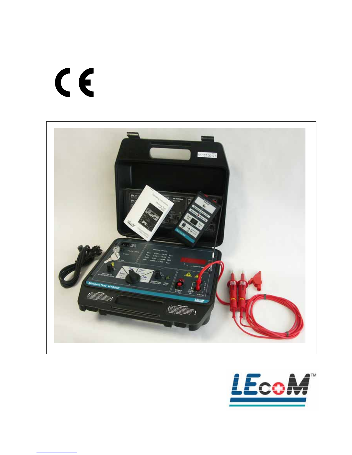
ORDER REFERENCE
1
Operating Instructions
MachineTest MT300E
WWW.LECOM.CN
Page 2

ORDER REFERENCE
2
Order Reference Order No.
MachineTest MT300E SA 9100 E
1 Basic instrument
1 residual voltage tester
2 safety test leads with fixed test tips, 2m, red
1 alligator clip, insulated
1 Mains cord – Euro plug, 2m
1 Operating instructions E/G/F
1 Test certificate with measured values
1 Declaration of conformity
1 Pack of Report templates (E/G/F)
Options:
1 Special high voltage safety measuring probe 2m, red SB 1000 E
1 Highly flexible measuring lead extension, 2m, red SB 1005 E
1 Highly flexible measuring lead extension, 15m, red SB 1015 E
Page 3

CONTENTS
3
Table of contents
1 INTRODUCTION .............................................................................................................4
1.1. General description...................................................................................................4
1.2. List of measured parameters.....................................................................................4
1.3. Standards applied .....................................................................................................4
2 SAFETY REGULATIONS.................................................................................................5
3 INSTRUMENT DESCRIPTION.........................................................................................7
3.1. Front panel................................................................................................................7
3.2. Accessory compartment and short instruction panel.................................................8
3.3 Front panel of hand-held residual voltage tester .......................................................9
3.4. Accessories.............................................................................................................10
4 MEASUREMENTS..........................................................................................................11
4.1 Voltage drop across PE conductor / resistance of PE conductor............................11
4.2 Insulation resistance................................................................................................13
4.3 Residual voltage......................................................................................................15
4.4 HV dielectric test (withstanding voltage test)...........................................................20
5 TECHNICAL SPECIFICATIONS.....................................................................................22
5.1 General (basic instrument)......................................................................................22
5.2 Functions (basic instrument)...................................................................................22
5.3 General (Residual Voltage Tester)..........................................................................23
5.4 Function (Residual Voltage Tester).........................................................................23
6 MAINTENANCE..............................................................................................................24
6.1 Cleaning..................................................................................................................24
6.2 Fuses ......................................................................................................................24
6.3 Periodic calibration..................................................................................................24
7 SERVICE........................................................................................................................25
Page 4

GENERAL
4
1. INTRODUCTION
Congratulations on your purchase of this test instrument which was developed to offer
realisation of all required tests and measurements on machines according to the
International Standard IEC 60204 and the European Standard EN 60204.
1.1. General description
The MachineTest MT300E offers very simple operation, easy to read large LED display
which enables reliable reading of test results even in dark environment. Due to
simplicity of the instrument it is sufficient for the operator to read this short booklet to be
familiar with operation procedures.
Portable double-wall plastic housing protects the instrument against mechanical shocks,
front panel with operating elements is protected by a rough cover.
A great advantages against similar products are two uniform test leads connected to
uniform test terminals which serve for all measurement functions.
All included accessories are placed under protection cover and cannot get lost. There is
also a clear short instruction label under the cover to remind the operator anytime how
to connect test leads to tested object and what are the limit values prescribed by the EN
60204 standard.
1.2. List of measured parameters
The following parameters can be tested /measured:
Voltage drop across PE conductor / Resistance of PE conductor
• test voltage <12 V AC
• test current >10 A AC
Insulation Resistance
• nominal test voltage 500 V DC
• test current >1 mA up to Rins = 500 kΩ
Residual voltage
• measurement after 1s / 5s
• safe level of residual voltage 60 V DC
HV Dielectric test (withstanding voltage)
• test voltage >1000 V AC supplied by isolated transformer having rated
power of 500 VA
• selection of tripping currents 10/50/100/200mA (due to capacitances)
1.3. Standards applied
IEC/EN 61010-1 ...........Basic safety standard
IEC/EN 61326-1 ...........EMC standard (noise and immunity)
IEC/EN 60204...............Safety of electrical equipment of electrical machines
DIN VDE 0113 .............Safety of electrical equipment of electrical machines
DIN VDE 0104
DIN VDE 0701
Page 5

SAFETY REGULATIONS
5
2. SAFETY REGULATIONS
This measuring device is only to be installed and operated by qualified
personnel and according to the technical data in compliance with the
safety precautions and regulations set forth below. Additionally, the use
of this equipment requires compliance with all legal and safety
regulations pertaining to each specific application. Similar regulations
apply to the use of accessories.
Operating electrical devices implies that parts of the device carry
dangerous voltages. Disregarding warning notices may lead to serious
physical injury and material damage.
It can be assumed that safe operation is no longer possible if the device
• Shows visible damage,
• Has been exposed to unfavourable conditions (e.g. storage beyond the
permissible climatic limits without adaptation to the ambient climate,
dewing etc.) or
• Has been exposed to major strain during transport
(e.g. been dropped from some height without visible external damage etc.).
Qualified Personnel
Are persons familiar with the setting up, installation, starting off and operation of the
device and possess a formal qualification required for such activities.
Special warnings in order to assure operator’s safety while carrying out the tests:
If the test instrument is used in manner not specified in this manual the
protection provided by the instrument may be impaired!
Do not use the instrument in explosive atmosphere!
In case of blown any fuse, follow the instructions in this manual to replace it!
Service intervention or calibration procedure is allowed to be carried out only by
a competent authorised person!
Page 6
SAFETY REGULATIONS
6
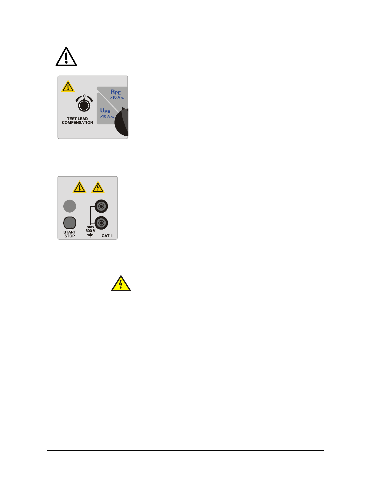
This symbol means: Please read the operating instructions with particular care!
Meaning of the symbol: Hazardous voltage generated by the
instrument may be applied to the test terminals!
- Intermittent use! An acoustic signal (beep) will
indicate a measuring time of 10s. To avoid
unintended overheating don’t measure continuously
with 10A. If the instrument is overheated the “HOT”
control LED at the display will indicate this and stop
the measurement.
- Use only standard or optional test leads supplied by your
dealer, otherwise the tests may be highly dangerous!
- Avoid direct contact with test tips, hazardous voltage
may be applied!
- Do not connect external voltage to test terminals
otherwise the instrument may be damaged or internal
fuse may blow!
- If the START/STOP control lamp can not be switched off
pressing the START/STOP key, then stop the
measurements immediately, unplug the mains cord and
let the instrument to be serviced!
+
∼
∼
_
Page 7
INSTRUMENT DESCRIPTION
7
3 INSTRUMENT DESCRIPTION
3.1 Front panel
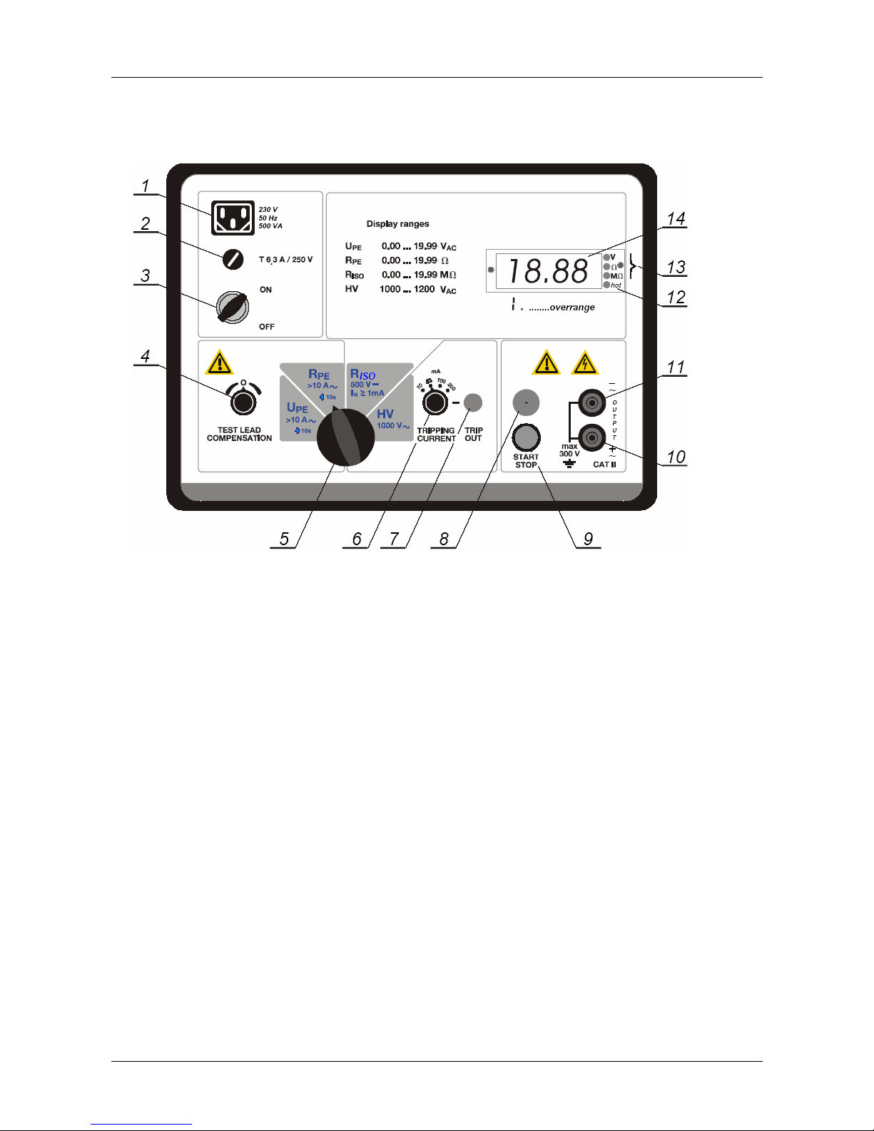
Fig. 01: Front panel
1 ............. Euro mains socket 230 V / 50 Hz, 500 VA.
2 ............. General fuse T 6.3 A / 250 V (5 × 20 mm).
3 ............. Mains key type ON / OFF switch.
4 ............. TEST LEAD COMPENSATION button to compensate resistance of test
leads in functions U
PE and RPE.
5 ............. Rotary switch to select one of four available measurement functions.
6 ............. TRIPPING CURRENT select tripping current for HV test (in case there is
some capacitive or resistive leakage current present at the tested machine).
7 ............. Yellow TRIP OUT control lamp to inform the operator that break-through
and thus trip out test voltage has occurred.
8 ............. MEASUREMENT ON control lamp which will light when any measurement is
running – take care, dangerous voltage may be applied to test terminals.
9 ............. START / STOP key to start or stop any measurement.
10 ........... Test terminal + ∼.
11 ........... Test terminal - ∼.
12 ........... Hot control lamp. It will light if the instrument is overheated in functions UPE
or R
PE. START button will not be operational (only in UPE and RPE functions)
until the lamp is off.
13 ........... Unit of displayed result.
14 ........... Red LED display.
Page 8
INSTRUMENT DESCRIPTION
8
3.2. Accessory compartment and short instruction panel
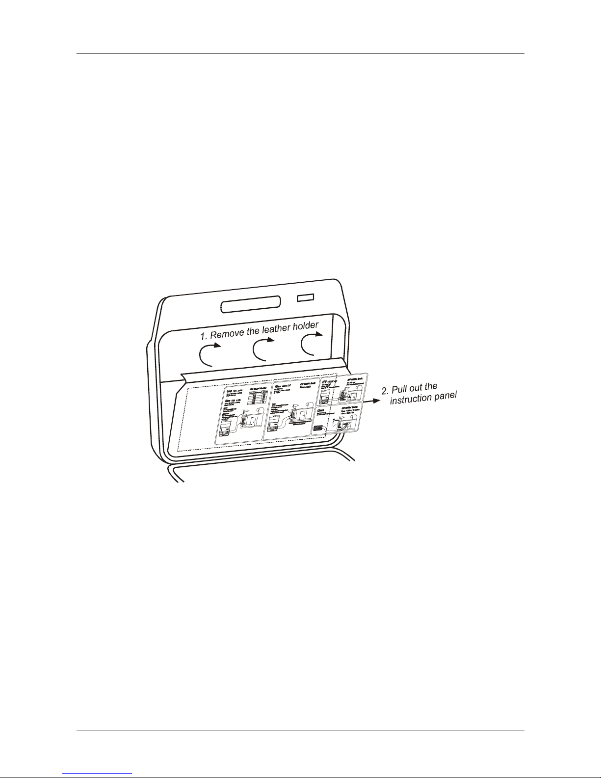
All required test accessories are kept in appropriate accessory compartment under the
casing cover. There is also an instruction panel with short instructions how to connect
test leads for a certain measurement as well as limit values of test results prescribed by
the EN 60204 European standard. The instruction panel is both side printed (EnglishFrench on one side and German on the other). The user can simply swap it to change
the language.
How to swap the instruction panel?
The panel is placed behind transparent foil, that is why it is necessary to remove black
leather holder at least at the upper side first, then the panel can be pulled out and
swapped, see the figure below.
Fig. 02: Instruction panel
Page 9
INSTRUMENT DESCRIPTION
9
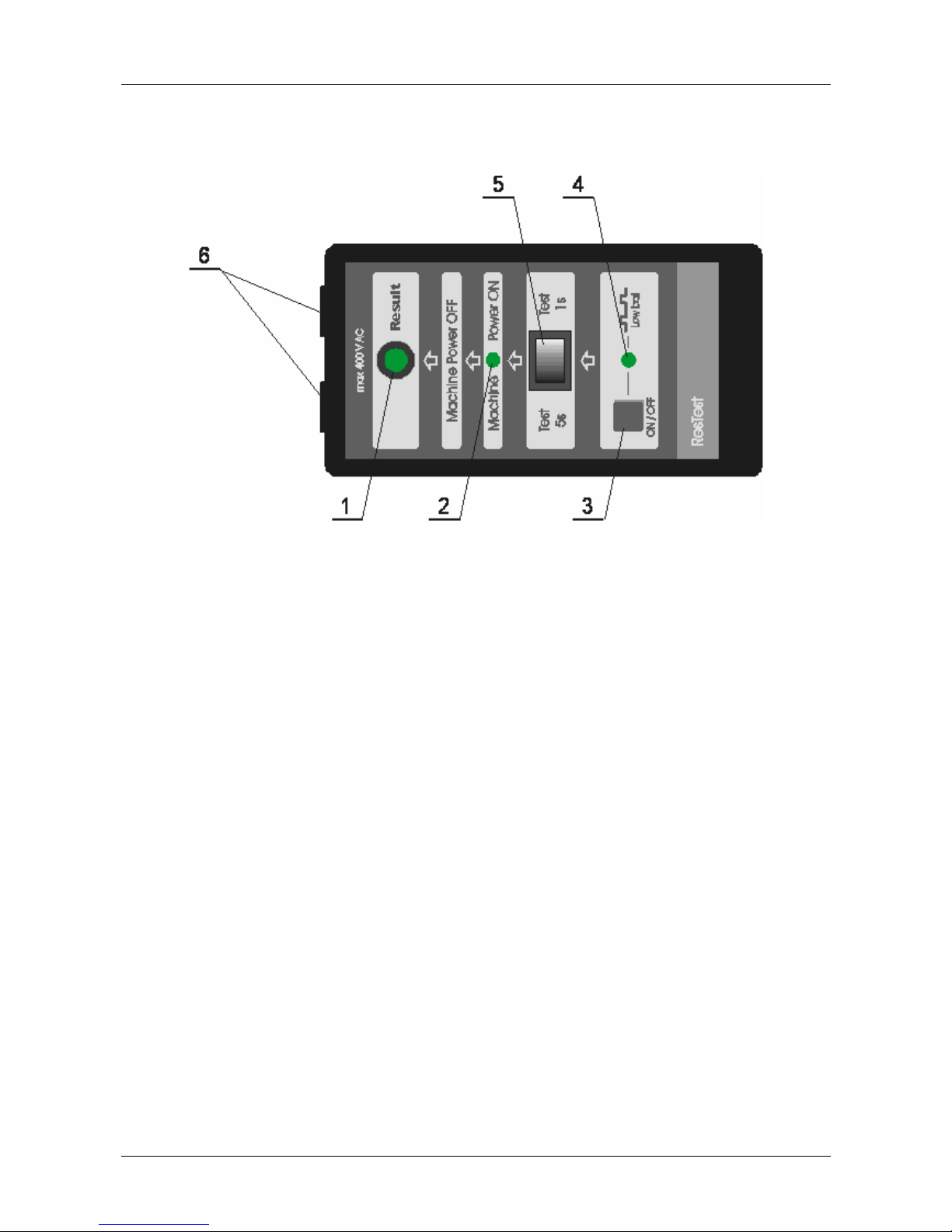
3.3 Front panel of hand-held Residual Voltage Tester
Fig. 03: Front panel of Residual Voltage Tester
1............. Green/red Result control lamp. Green colour is “on” when the value of
Residual Voltage (result) is below 60 V DC 1s / 5s after switching off tested
machine. Red colour is “on” when the value of Residual Voltage (result) is
above 60 V DC 1s / 5s after switching off tested machine.
2............. Red Machine Power on control lamp. It is automatically switched “on” a
few seconds after detecting stable mains AC or DC voltage connected to
test terminals.
3............. ON/OFF key to switch the tester “on” or “off”. Automatic “off” occurs in case
the tester has not been used for more than 5 minutes.
-Linear mode (Description see 4.3):
Switch on the tester pressing the on/off key and keeping it pressed for
approx. 2s until all three red control lamps (bat, Machine Power on and
Result) go “on”, then release the on/off key. After 1s two lamps go “off” while
the bat lamp stays “on”. Residual Voltage Tester is thus in Linear mode.
-Non-linear mode (Description see 4.3):
Switch on the tester pressing the on/off key and releasing it. Bat lamp goes
“on”, Residual Voltage Tester is thus in linear mode.
4............. Red Bat control lamp. The lamp continuously lights if battery is in good
condition and starts to blink when the battery is in empty condition.
5............. Test duration switch to select waiting time (1s – plug test or 5s – internal
test) activated after automatic recognition of switching “off” tested machine.
6............. Test terminals (banana sockets).
Page 10
INSTRUMENT DESCRIPTION
10
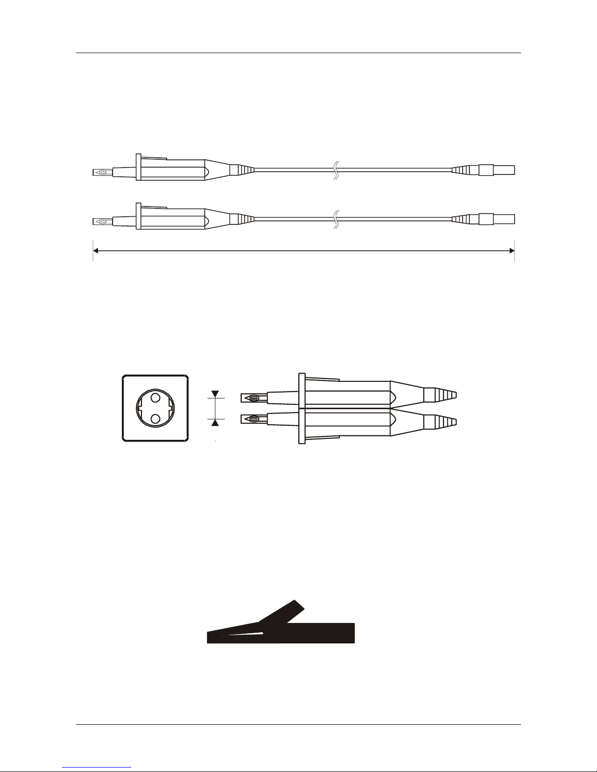
3.4 Accessories
Two test leads CAT III, 1000V, double insulation
Fig. 04: Test leads, parallel combination of both test tips which fit to mains outlet
Alligator clip
Fig. 05. Insulated alligator clip
l = 2 m
19 mm
Page 11
MEASUREMENTS
11
4 MEASUREMENTS
4.1 Voltage drop across PE conductor / resistance of PE conductor
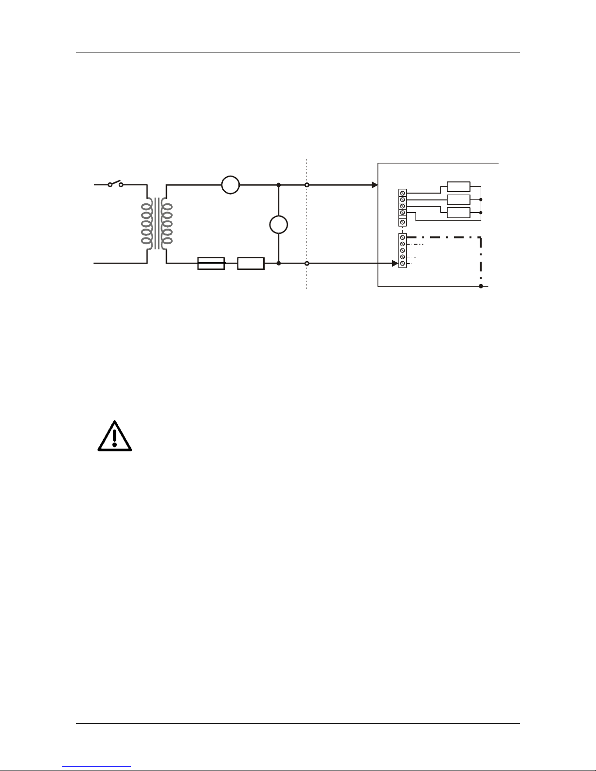
Measurement principle
Fig. 06. Voltage drop / resistance measurement principle
Rt.l.......... test lead resistance
Result in voltage drop measurement is given in (V) and is scaled to test current of 10 A.
Result in resistance measurement is given in (Ω).
Warnings!
• Make sure tested object to be disconnected from mains voltage!
• Do not apply any external voltage to test terminals, internal fuse
may be blown and the instrument may be damaged! (Instrument is
protected against extraneous overvoltage up to 250 V AC)
• Make sure contact between test tips (alligator) and tested object to
be good (remove oxide or colour at the surface of tested object
before carrying out the test)!
• Compensate resistance of test leads before carrying out the test!
Test procedure
STEP 1 Prepare the instrument
- Place it into such position that both test points of tested object will be
reachable by the test tips (take into account the 2 m long test leads) or
use optional test lead extensions.
- Connect the instrument to mains voltage via mains cord.
- Connect test leads to terminals of the instrument.
- Select UPE or RPE function setting rotary switch to UPE or RPE position.
- Switch on the instrument, initial display state is present (- - -).
Rint.
Rt.l.
Rt.l.
Fuse
A
V
230 V
50 Hz
11 V
L1
L2
L3
N
PE
S = 4 mm (example)
2
PE collector
+
_
U (R)
PE PE
∼
∼
Fuse
Page 12
MEASUREMENTS
12
STEP 2 Compensate resistance of test leads
- Connect alligator clip to a test tip.
- Short free test tip and alligator clip.
- Select UPE function (regardless of which function - UPE or RPE will be
carried out later).
- Press the START/STOP key and set display value to 0.00 V adjusting the
TEST LEADS COMPENSATION button.
- Press the START/STOP key again to stop the measurement. The
instrument is now ready for carrying out measurements.
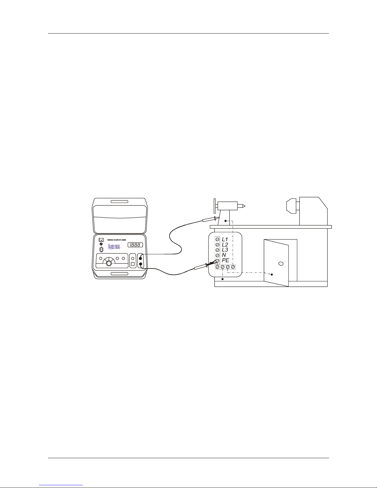
STEP 3 Carry out the measurement
- Connect one test lead to one test point of tested object (PE terminal or a
part of conductive housing) using alligator clip, see the figure below.
- Connect the other test tip to another test point of tested object (assure
good contact).
Fig. 07: Connection of test leads
- Press the START/STOP key to start the measurement, wait 10 s until
acoustic signal (beep) is effected, then read displayed result and press
the START/STOP key to stop the measurement.
- Disconnect test leads.
- Write down read result.
Note!
Voltage drop (UPE) measurement is required by the EN 60204 standard and shall be
carried out whenever test result is to be entered in to the measurement protocol
according to EN 60204 requirements. Result is in (V).
Resistance (RPE) measurement is not required by the EN 60204 standard and shall be
carried out when local prescriptions restrict resistance of the protective conductor or if
the instrument is used for appliance testing. (e.g.: DIN VDE 0701)
Page 13
MEASUREMENTS
13
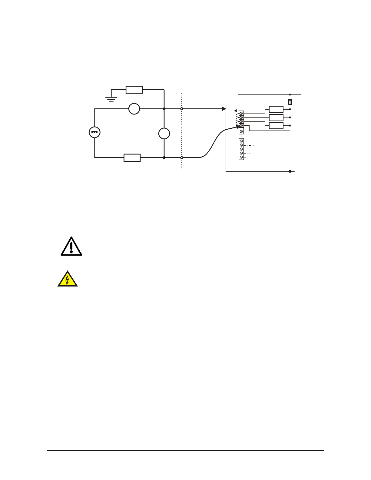
4.2 Insulation Resistance
Measurement principle
Fig. 08: Insulation resistance measurement principle
Practical measurement
Warnings!
• Make sure tested object to be disconnected from mains voltage!
• Do not apply any external voltage to test terminals, make sure object
to be tested is de-energised!
• Switch “on” main switch of tested object as well as other switches,
in order to include all electronic parts of tested object in the test!
• Do not touch any part of tested object during the test!
• Discharge tested object after test end (capacitors may store
dangerous voltages)!
Test procedure
STEP 1 Prepare the instrument
• Place it into such a position that both test points of tested object will be
reachable by the test leads (take into account the 2 m long test leads) or
use optional test lead extensions.
• Connect the instrument to mains voltage via mains cord.
• Connect test leads to test terminals of the instrument.
• Select Rins function setting function rotary switch to Rins position.
• Switch on the instrument, initial display state is present (- - -).
Rint.
A
V
500 V d.c.
L1
L2
L3
N
PE
PE collector
∼Ω
5 M
+
_
Ri
short all
live parts
∼
∼
Page 14
MEASUREMENTS
14
STEP 2 Prepare the object to be tested
- Make sure tested object to be disconnected from mains voltage!
- Switch “on” main switch of tested object as well as other switches, in
order to test all electronic parts of tested object!
- Short all live terminals of tested object (L1, L2, L3, N).
STEP 3 Carry out the measurement
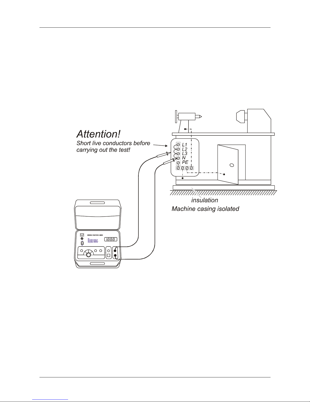
- Connect one test lead to shorted live terminals using alligator clip.
- Connect the other test tip to PE terminal of tested object, see the figure
below.
Fig. 09: Connection of test leads
- Press the START/STOP key to start the measurement, wait until result
is stable then read displayed result.
- Press the START/STOP key to stop the measurement.
- Disconnect test leads.
- Write down read result.
−
∼
ATTENTION !
(only if tested machine is grounded i.e.
not isolated)
Test lead connection to “- ~” test
terminal should be connected to the
housing (PE terminal) otherwise the test
result will be below the actual value
(5MOhm in parallel) !
Page 15
MEASUREMENTS
15
4.3 Residual voltage
Purpose of the measurement is:
• To check if there is no hazardous voltage at mains one-phase or three-phase
plug after pulling out the plug (wall-plug connected machines).
• To check if there is no hazardous voltage at any accessible electric
component inside the tested machine after switching off the machine (wall-plug
and permanently connected machines).
Safe conditions must be assured with appropriate electric and/or mechanic construction
of tested machine. The conditions must be assured also during the machine is powered
but we must be aware that some components can become accessible only after deenergizing the machine e.g. plug pins or components behind electrically blocked
barriers.
Test of residual voltage is to be done only if there is an electric charge present
higher than 45µC, otherwise the charge may be considered as safe one.
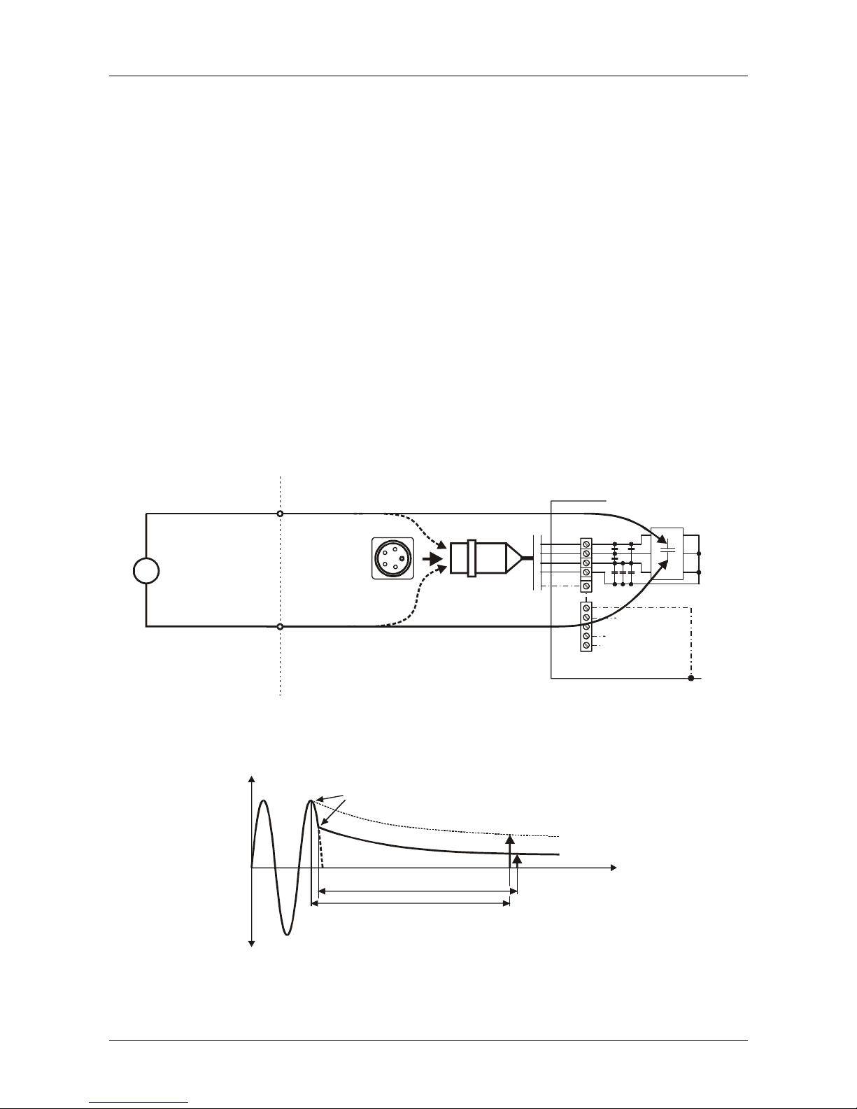
Measurement principle
Fig. 10: Residual voltage measurement principle
Residual voltage measurements of AC voltage can be carried out in linear mode or nonlinear mode – see next page for detailed explanations.
Fig. 11. Graphic presentation of URES in case of measurement at mains plug or
inside tested machine (AC voltage)
V
L1
L2
L3
N
PE
PE collector
all combinations
among mains plug
terminals
MAINS
+
_
C
60 V d.c.max
after 1s
60 V d.c.max
after 5s
∼
∼
1s / 5s
U (correct value)
RES
U
RES
1s / 5s
U
coincidental switch off
at any mains voltage
t
Page 16
MEASUREMENTS
16
In case of measurement of DC voltage, only one measurement is enough to be carried
out (as the result is repeatable).
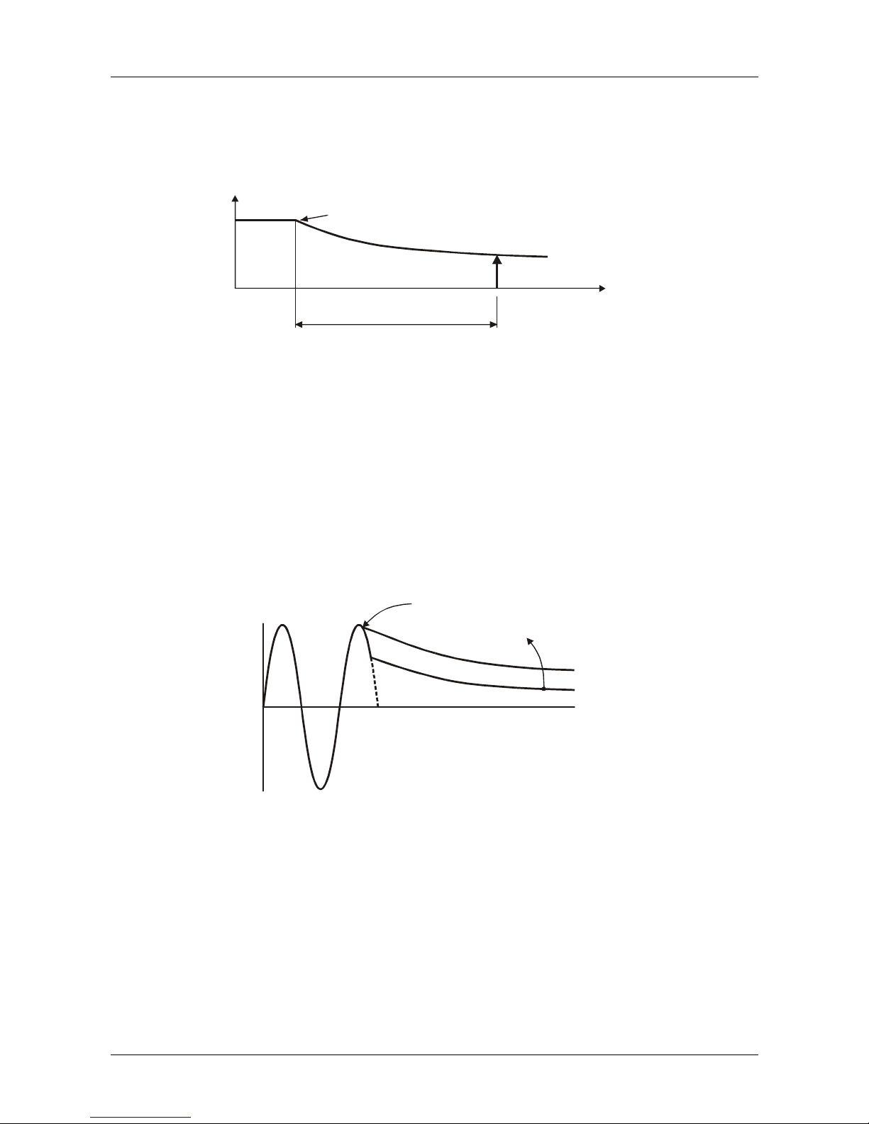
Fig. 12. Graphic presentation of U
RES in case of measurement inside tested
machine (DC voltage)
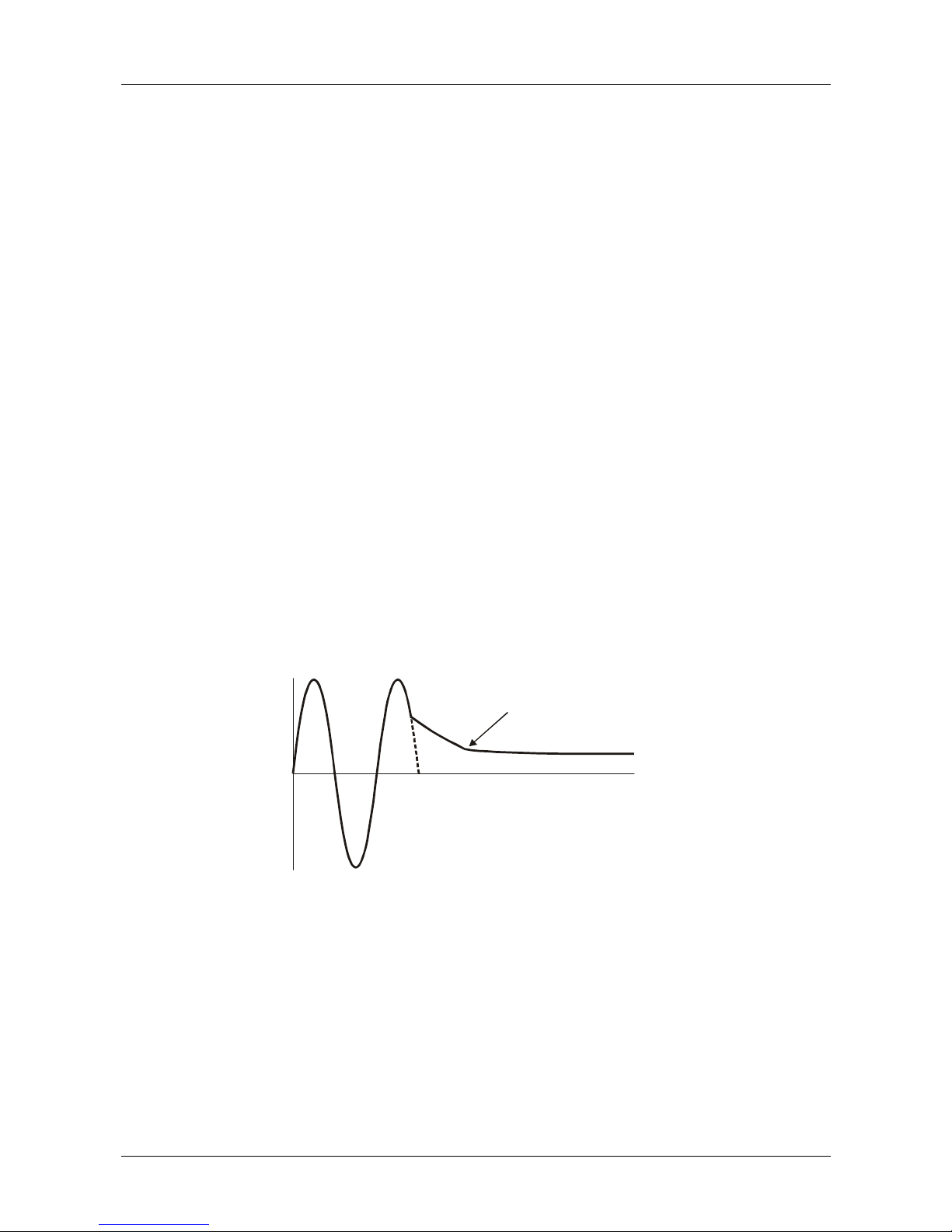
In order to avoid inconvenient repeating of the measurement in some cases even when
measuring AC voltage, the Residual Voltage Tester offers two modes of measurement
namely:
a) Linear mode
This mode shall be used when dealing with known objects which comprise only
“linear” internal components (R,L,C). In such case simple exponential voltage
decreasing is present after switching off tested object. Such a diagram is then
mathematically scaled to maximal value of mains voltage and thus the
measurement is not required to be repeated, see the figure below.
Fig. 13. Diagram of voltage decreasing in case “linear” components only
are involved
u
diagram is automatically
scaled to max. value of
mains voltage
t
U
RES
1s / 5s
U
switch off always at the same DC voltage
t
Page 17
MEASUREMENTS
17
In linear mode the Residual Voltage Tester recognizes three standard mains
voltages automatically:
110 V ......................Uin = 110 V ± 10%
230 V ......................Uin = 230 V ± 10%
400 V ......................Uin = 400 V ± 10%
In order test result to be always on “safe side”, measured residual voltage is
scaled to maximal possible value i.e.:
171 Vp = 110 V × 1.1 × 1.41 ......standard mains voltage 110 V
357 Vp = 230 V × 1.1 × 1.41 ......standard mains voltage 230 V
620 Vp = 400 V × 1.1 × 1.41 ......standard mains voltage 400 V
If input voltage is out of any standard voltage ± 10%, then the tester scales
result to maximal actual value.
Example: Uin = 173 V (under standard voltage 230 V ± 10%) ⇒ result will be
scaled to 244 Vp = 173 V × 1.41
b) Non-linear mode
This mode shall be used when dealing with non-linear or unknown objects
which consist of R, L, C components and also non-linear internal components
(relays, gas lamps etc.). In this case a diagram of voltage decreasing (after
switching off tested object) may be quite unpredictable, see the figure below,
and can not be scaled to maximal voltage value.
Fig. 14. Diagram of voltage decreasing in case of non-linear components
are involved
Disadvantage of this mode is that the measurement must be repeated several
times in order at least once tested object to be switched off at nearly max. value
of mains voltage.
In order to assure reliable result (switching off at least once at approx. max. mains
voltage) the test should be repeated at least 15 times (mathematical statistics). Final
result is positive if all partial results were positive and is negative if only one partial
result was negative.
u
relay may be
switched off
t
Page 18
MEASUREMENTS
18
Practical measurement
STEP 1 Prepare the tester
• Connect two test leads to the Residual Voltage Tester.
• Select appropriate measurement mode as follows:
• Linear mode
Switch on the tester pressing the on/off key and keeping it pressed for
approx. 2s until all three red control lamps (bat, Machine Power on and
Result) go “on”, then release the on/off key. After 1s two lamps go “down”
while the bat lamp stays “on”. Residual Voltage Tester is thus in Linear
mode.
• Non-linear mode
Switch on the tester pressing the on/off key and releasing it. Bat lamp
goes “on”, Residual Voltage Tester is thus in linear mode.
• Select appropriate waiting time effected from switching-off moment until
taking the measurement of URES. 1s (measurement at mains plug) or 5s
(measurement inside tested machine) can be selected.
STEP 2 Carry out the test
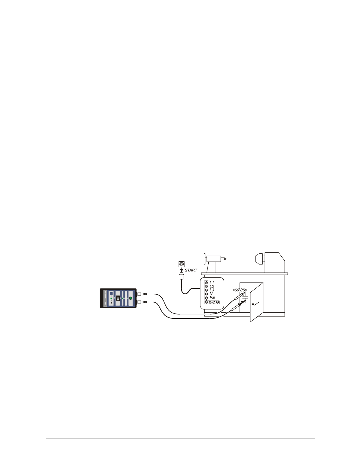
• Connect test leads to tested machine, see the figure below.
Fig. 15. Connection of test leads
In case of measurement at mains plug, corresponding T-distributor
should be used, see the next figure.
max 400 V AC
Result
Machine Power OFF
Machine Power ON
Test
1s
Test
5s
ON / OFF
Low bat
Page 19

MEASUREMENTS
19
Fig. 16. Connection of test leads and tested machine via T-distributor
• Switch on (or connect mains plug to mains outlet), Machine Power ON
lamp goes “on” as soon as stable AC or DC voltage (higher than 60 V DC
or peak AC) is detected at test terminals.
• Pull out mains plug of tested machine (measurement at plug terminals) or
switch off mains switch (measurement inside the machine) and wait for
result to be displayed (red or green control lamp). Green colour means
the level of measured residual voltage is below 60 V DC ⇒ OK while red
one means the level is above 60 V DC ⇒ not OK.
• Valid for non-linear mode only: Repeat the measurement at least 15 times
- see explanation under “Measurement principle”. If none of test results is
above prescribed limit value (always green lamp) the machine can be
considered as to pass the test.
• Write down the test result (OK or not OK).
Notes!
• Linear mode only: If mains voltage is interrupted at too low value (impossible to scale
test result), then the tester requires another measurement flashing green Result lamp!
• If already detected stable mains voltage present at test terminals (green Machine
Power on lamp lights) changes for more than 10%, then the Machine Power on lamp
starts to flash until a new stable voltage is detected!
• Make sure always to take the first test result (displayed within 1s / 5s after mains
voltage disconnection). It might happen at extremely high capacitances (slow voltage
discharge) that the measurement will be started again automatically after completion
the first one. Then a further not valid test result could be displayed.
tester
tester machine
machine
mains
mains
Three-phase distributo r
One-phase distributor
Page 20
MEASUREMENTS
20
4.4 HV Dielectric test (withstanding voltage test)
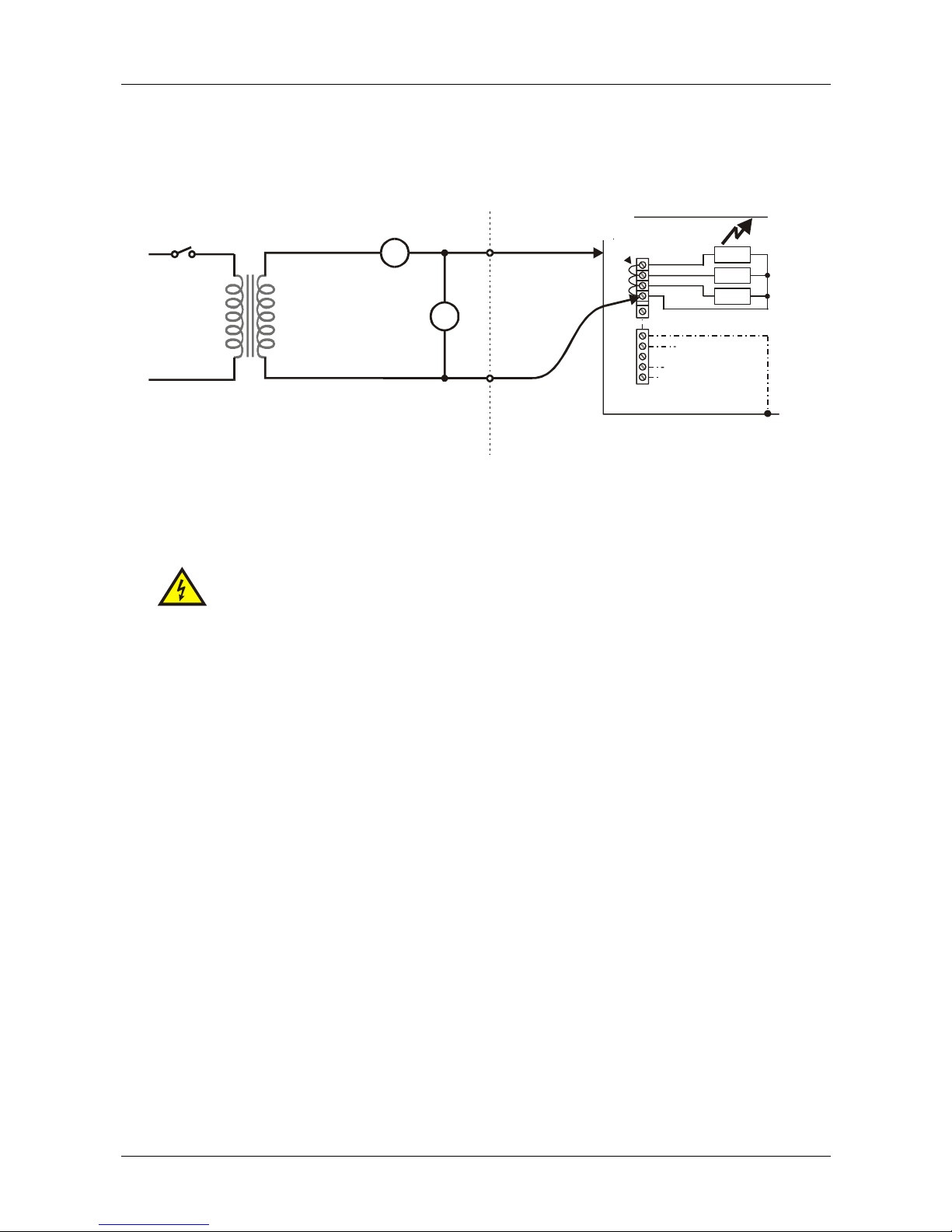
Measurement principle
Fig. 17: Principle: HV Dielectric test
Practical measurement
Warnings!
- Make sure tested object to be disconnected from mains voltage!
- Dangerous measurement! Test voltage of over 1000 V AC supplied
by 500 VA transformer is applied to test tips!
- Make sure there is no third party person around the tested object
when the test is being carried out and national safety requirements
are fulfilled (e.g.: DIN VDE 0104) !
How to carry out the measurement
STEP 1 Prepare the machine to be tested
- Assure tested object to be disconnected from mains voltage.
- Switch “on” main switch of tested object as well as other switches, in
order all electronic parts of tested object to be included in the test!
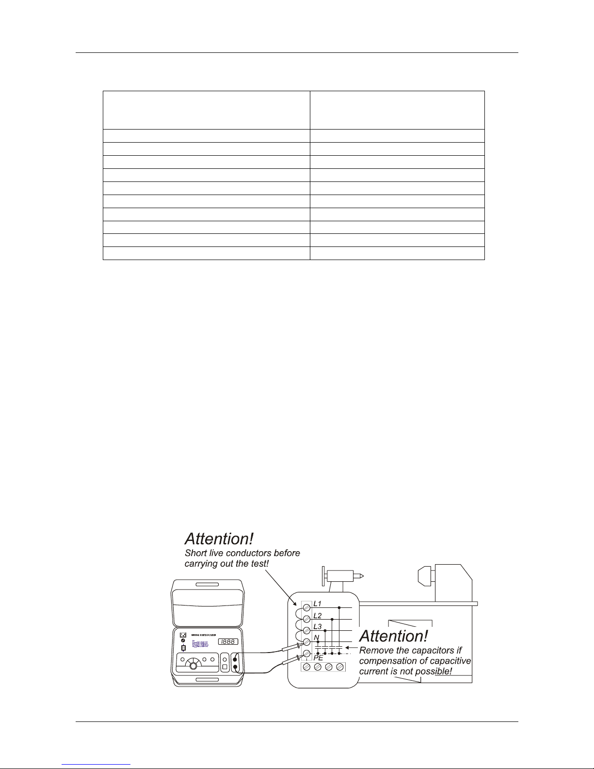
- Short all live terminals of tested object (L1, L2, L3, N).
- Check electric circuit diagram of the machine or the machine itself with
regard to mains part connection. There may be some capacitors
connected between live parts (L1, L2, L3, N) and PE terminal (housing)
which serve as EMC filter or noise suppressor etc., see the figure below.
In case the capacitors are not rated for AC voltage of up to 1000 V, take
care to remove them before carrying out the test otherwise they may be
damaged. If the capacitors are rated for voltages of up to 1000 V AC then
they may remain in place if their capacitance is not too high (capacitive
current can not be compensated if the capacitance is too high), see the
next table.
A
V
230 V
50 Hz
1000 V
L1
L2
L3
N
PE
PE collector
+
_
short all
live parts
min. 1s!
∼
∼
Page 21
MEASUREMENTS
21
Total capacitance C
(parallel connection of all capacitors)
(nF)
Capacitive current Ic
(at test voltage of 1100 V / 50 Hz)
(mA)
4.7 1.6
10 3.5
27 9.3
47 16.2
68 23.5
100 35
220 76
330 114
470 162
680 235
To avoid tripping out test voltage, tripping current at the instrument
shall be set to the closest value above estimated test current.
STEP 2 Prepare the instrument
- Place it into such position that both test points of tested object will be
reachable by the test tips (take into account the 2 m long test leads) or
use optional test lead extensions.
- Connect the instrument to mains voltage via mains cord.
- Connect test leads to test terminals of the instrument.
- Set rotary switch to HV position.
- Switch on the instrument, initial display state is present (- - -).
STEP 3 Carry out the test
- Press the START/STOP key to start the measurement
- Contact one test prod to PE terminal
- Contact with the second test prod the shorted live terminals and wait for
at least 1s (see figure below)
- Remove test prods
- Press the START/STOP key again to stop the measurement.
- Write down the test result (OK or breakdown).
Fig. 18. Connection of test leads
Page 22

TECHNICAL SPECIFICATION
22
5 TECHNICAL SPECIFICATIONS
5.1 General (basic instrument)
Power supply..........................................................230 V ±10%, 50 Hz ±5%
Max. power consumption........................................500 VA
Display....................................................................3 ½ dig. LED, character height 20 mm
Fuses......................................................................T6.3A / 250V (5 × 20 mm)… front panel
T16A / 500V (6.3 × 32 mm)…inside
Dimensions (w × d × h (incl. handle)) .....................345 × 170 × 260 (320) mm
Weight.....................................................................8.5 kg
Protection classification ..........................................Class I (Basic insulation)
Over-voltage category.............................................Cat II 300 V IEC 61010
Pollution degree......................................................2
Degree of protection ...............................................IP 40
Casing.....................................................................double wall plastic, black
Working temperature range....................................-10 to 40°C
Operating temperature range..................................0 to 40°C (acc. refers to this range)
Reference temperature range.................................23 ±2 °C
Storage temperature range.....................................-30 °C to +60 °C
Max. humidity..........................................................85 % RH (0 to 40 °C)
Reference humidity range.......................................40 % to 60 % RH
5.2 Functions (basic instrument)
Voltage drop across PE conductor (scaled to test current of 10 A AC)
Display range..........................................................0.00 to 19.99 V
Accuracy.................................................................±(5% + 0,1V)
Test current.............................................................>10 A AC (at mains voltage 230V
±10%, standard 2m test leads and max.
external resistance of 0.33Ω
Test voltage............................................................<12 V AC, floating output
Measurement principle............................................two-wire (manual compensation of test
Lead resistance)
Compensation of test leads' resistance ..................at least up to 0.09 Ω = two test lead
extensions (with regard to standard test
leads)
Protection in case of test leads connected
to mains voltage......................................................fuse T 16 A / 500 V
Resistance of PE conductor
Display range..........................................................0.00 to 19.99 Ω
Accuracy.................................................................±(5% + 5D)
All other specifications equal as for voltage drop measurement
Page 23

TECHNICAL SPECIFICATION
23
Insulation Resistance
Display range..........................................................0.00 to 19.99 MΩ
Measurement range................................................0.20 to 19.99 MΩ
Accuracy.................................................................±(5% + 5D)
Nominal test voltage ...............................................500 V DC, terminal “-~” grounded
Test current generator capability ............................>1 mA DC
Short circuit test current..........................................<5 mA DC
HV Dielectric test (Withstanding Voltage)
Nominal test voltage...............................................1000 V AC, floating output
Actual test voltage ..................................................1000 up to 1250 V AC (230 V ±10%,
open circuit)
Accuracy of displayed test voltage..........................actual voltage –0 up to +30V
Supply transformer power.......................................>500 VA
Tripping current.......................................................10 mA, 50 mA, 100 mA or 200 mA
Accuracy of tripping current....................................±20% of preset nominal value
Trip out time after reaching set tripping current ......<30 ms
5.3 General (Residual Voltage tester)
Input resistance ......................................................20 MΩ
Power supply..........................................................9V battery
Dimensions (w × d × h)...........................................85 × 35 × 160 mm
Weight.....................................................................0.3 kg
Protection classification ..........................................II (double insulation)
Over-voltage category.............................................II 300 V
Pollution degree......................................................2
Degree of protection ...............................................IP 40
Casing.....................................................................plastic, black
Working temperature range....................................-10 to 40°C
Operating temperature range..................................0 to 40°C (accuracy refers to this
range)
Reference temperature range.................................23 ±2 °C
Storage temperature range.....................................-30 to +60°C
Max. humidity..........................................................85 % RH (0 to 40 °C)
Reference humidity range.......................................40 to 60 % RH
5.4 Function (Residual Voltage Tester)
Residual Voltage
Max input voltage....................................................440 V AC or 620 V DC
Start trigger (automatic)..........................................∆U/∆t > 20 V/s
Waiting time after automatic trigger........................1s or 5s
Safe level of Residual Voltage................................60 V DC
Display....................................................................green/red LED
Measurement principle............................................two-wire
Page 24

MAINTENANCE, SERVICE
24
6 MAINTENANCE
6.1 Cleaning
Use soft patch, slightly moistened with soap water or alcohol to clean the surface of the
instrument or residual voltage tester. Let the testers dry totally after being cleaned
before using them.
Notes!
• Do not use liquids based on petrol or hydrocarbons!
• Do not spill cleaning liquid over the instruments!
6.2 Fuses
There are two fuses in the basic instrument.
a) General fuse (front panel): Type T6.3A / 250 V 5 × 20 mm.
The fuse may be blown if there is no display segment “on” even at
connected mains voltage and mains switch turned “on”. It may be
replaced with a new one by an operator himself. Fuse cover on front
panel (pos. 2, fig. 01) is to be unscrewed and blown fuse replaced. It is
required to use prescribed fuse only otherwise the instrument may be
damaged.
b) Auxiliary fuse (inside the instrument): Type T16A / 500 V 6.3 × 32 mm.
The fuse may be blown if “l .” is displayed in RPE / UPE function even at
short-circuited test leads. It may be replaced by authorized service
personal only. It is required to use prescribed fuse only otherwise the
instrument may be damaged. When opening the instrument it is
recommended to place it to vertical position.
Warning: All the weight (8 kg) is fixed to front panel!
The Residual Voltage Tester does not contain any fuse!
6.3 Periodic calibration
It is essential that measurement instrument (basic instrument as well as residual voltage
tester) is regularly calibrated. For occasional use, we recommend an annual calibration
to be carried out. When the instrument is used continuously every day, we recommend
a calibration interval of sixth months.
Page 25

MAINTENANCE, SERVICE
25
7 SERVICE
Dear customer,
This instrument has been developed, designed and manufactured by experts according
to state-of-the-art aspects.
years
WARRANTY
1 years entitlement to repairs free of charge in case of malfunction of the
instrument excluding damage caused by misuse.
If it is used according to specification we shall guarantee proper functioning and
calibration for two years from the day of purchase. We decline any responsibility for
damages resulting from improper use, inexpert treatment and operation or overstressing.
Should some reason of complaint arise all the same please contact your local service
centre with as detailed a description of the cause of complaint as possible, the serial
number and copy of the invoice or delivery note.
Maintenance work must only be undertaken by trained and qualified staff and during the
warranty period only by authorised service centres.
NOTE:
This manual does not contain all detailed information for all the product types for clarity
reasons and is therefore not able to present every possible case concerning the setting
up, operation or maintenance.
Should you require additional information or encounter particular problems which are
not dealt with in enough detail in the manual please contact the local representative.
Furthermore, please note that the contents of this manual are not part of former or
existing agreements, promises or legal relations, not are they intended to amend these.
All the obligations result from the respective purchase agreement which also contains
the complete and solely valid warranty conditions. These contractual warranty
conditions are neither extended nor restricted by the statements in this manual.
24hr service hot line: +86-10-96096710
www.lecom.cn
1
Page 26

 Loading...