

Leclerc Looms ARTISAT 36 inch, 1009-3628 Assembly Manual
1573 Savoie
C. P. 4 Plessisville, Qc.
G6L 2Y6
TEL: 819-362-7207
FAX: 819-362-2045
www.leclerclooms.com
info@leclerclooms.com
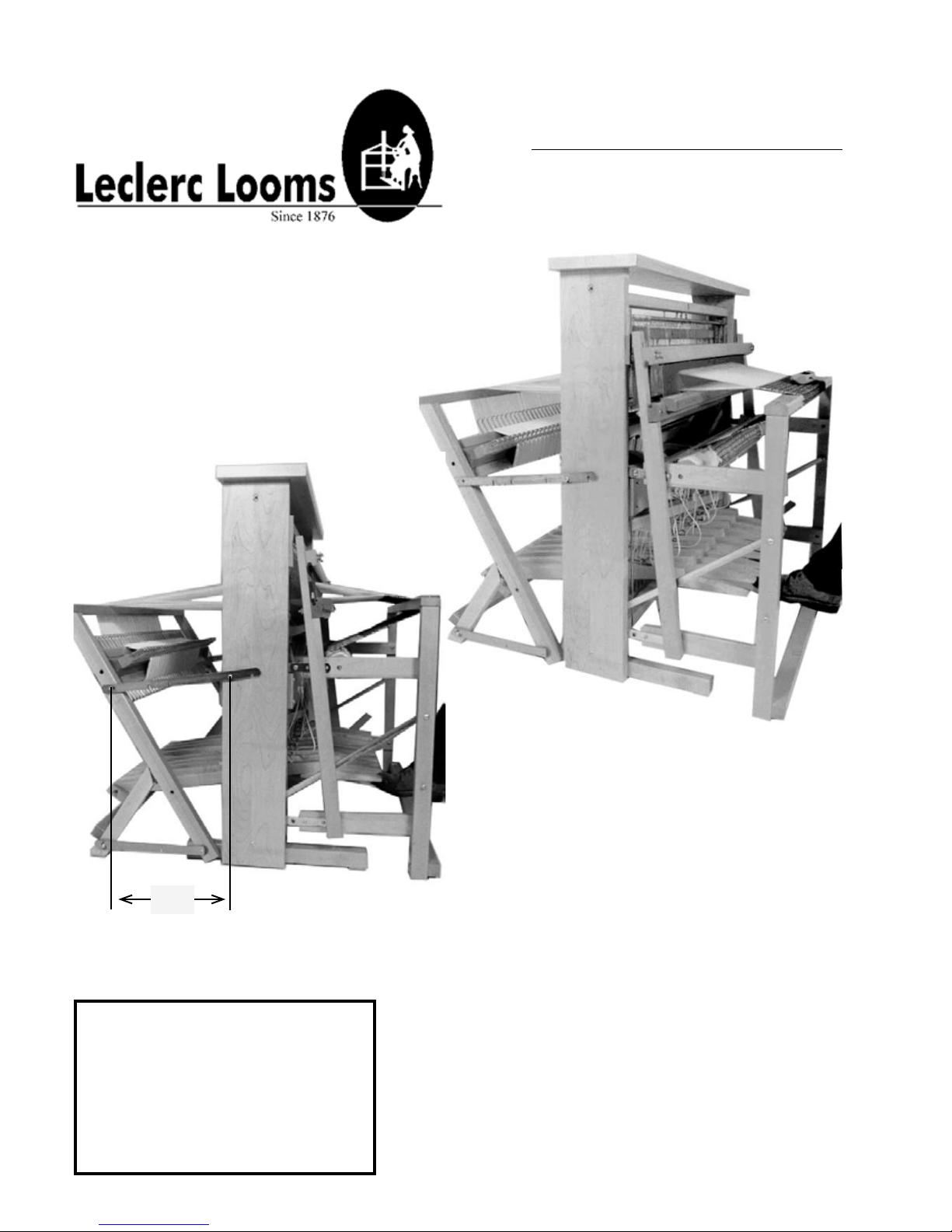
ARTISAT 36” JACK-TYPE
8 SHAFTS BACK HINGE
TREADLES
1009-3628
IMPORTANT
14 1/8"
Loom Prepared by:_____________
Inspected by:_________________
Date:____________________
On receiving the loom, unpack and lay
out the loom components.
Do NOT discard any packing material until all
parts are inventoried.
Check the parts received against the
parts list on pages #2 to #6 of the assembly
instructions. Report any discrepancies to
Leclerc immediately.
To assemble this loom, a minimum of 2
people are needed but it is recommended
you use 3.
1
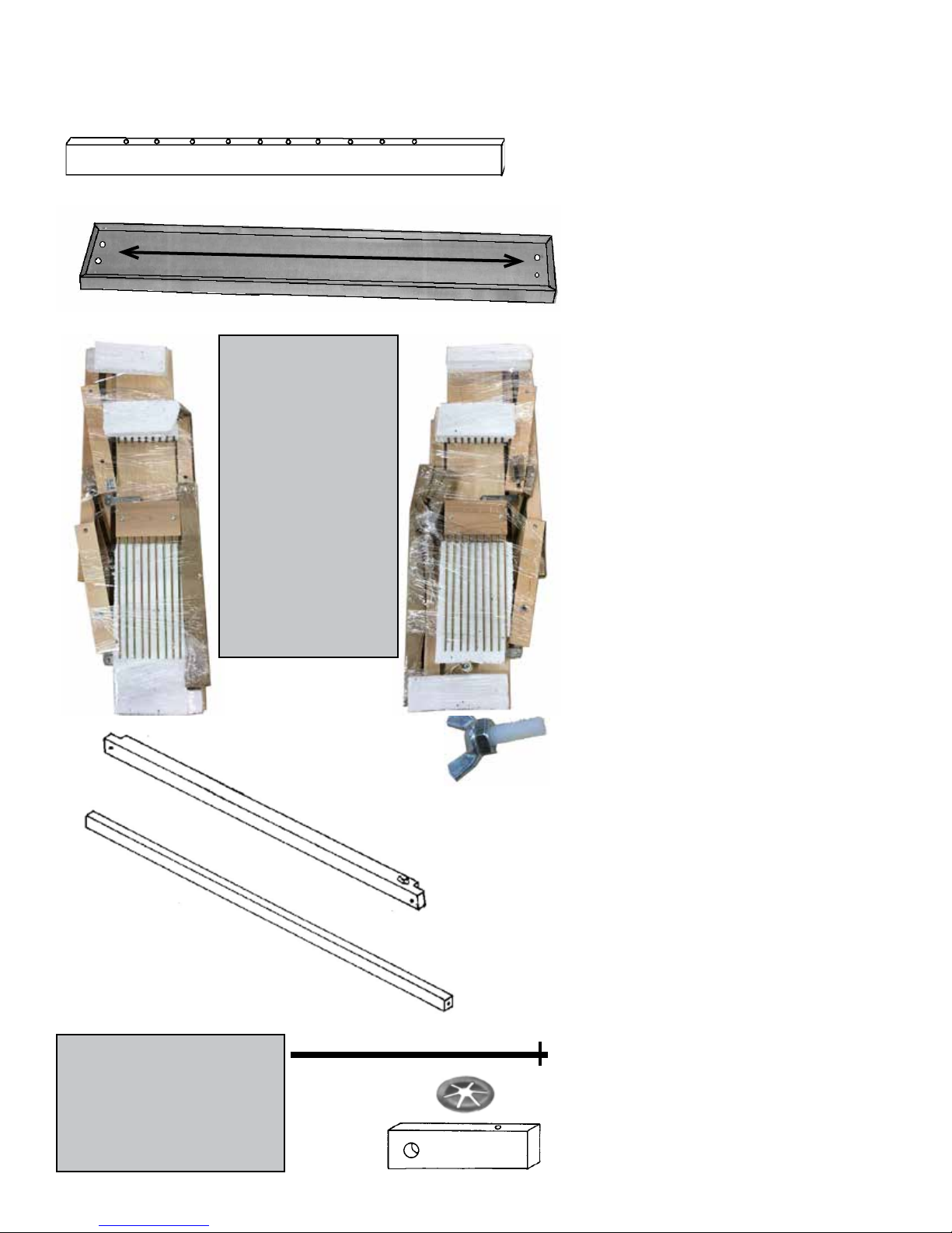
PARTS LIST
39¾"
41½ cc
Note for Leclerc in
French:
1) Poser les 2 vis de la
base de pattes arrière pour
le crochet.
Tête ronde no 12, 1" avec
rondelle de nylon
2) Poser la pièce letée
du contrôle de friction sur
la patte arrière gauche.
3) Faire les trous sur les
sabots pour le séparateur
de pédale + les trous pour
pentures
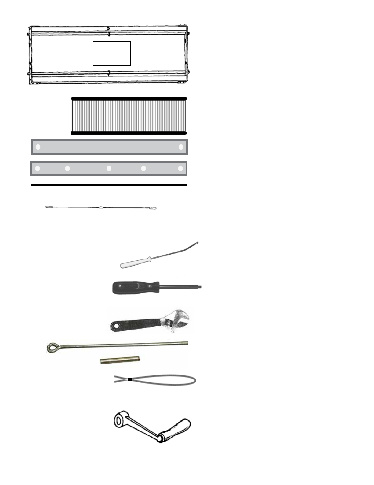
8 FLOATING LAMS
1 CASTLE TOP COVER
1 LEFT-HAND SIDE
with base packed seperatly
1 RIGHT-HAND SIDE
with base and brake treadle packed
seperatly
1 friction control system bolt
Note for Leclerc in French:
4) Corde de frein coton 40"
5) Surveiller l'amanchement
avec les pattes avant.
1 FRONT CROSS-MEMBER
1 MIDDLE LOWER CROSS-MEMBER
1 TREADLE ROD 27 ¾” with one push nut
1 MORE PUSH NUT 7/16”
2 TREADLE set SUPPORTS
2
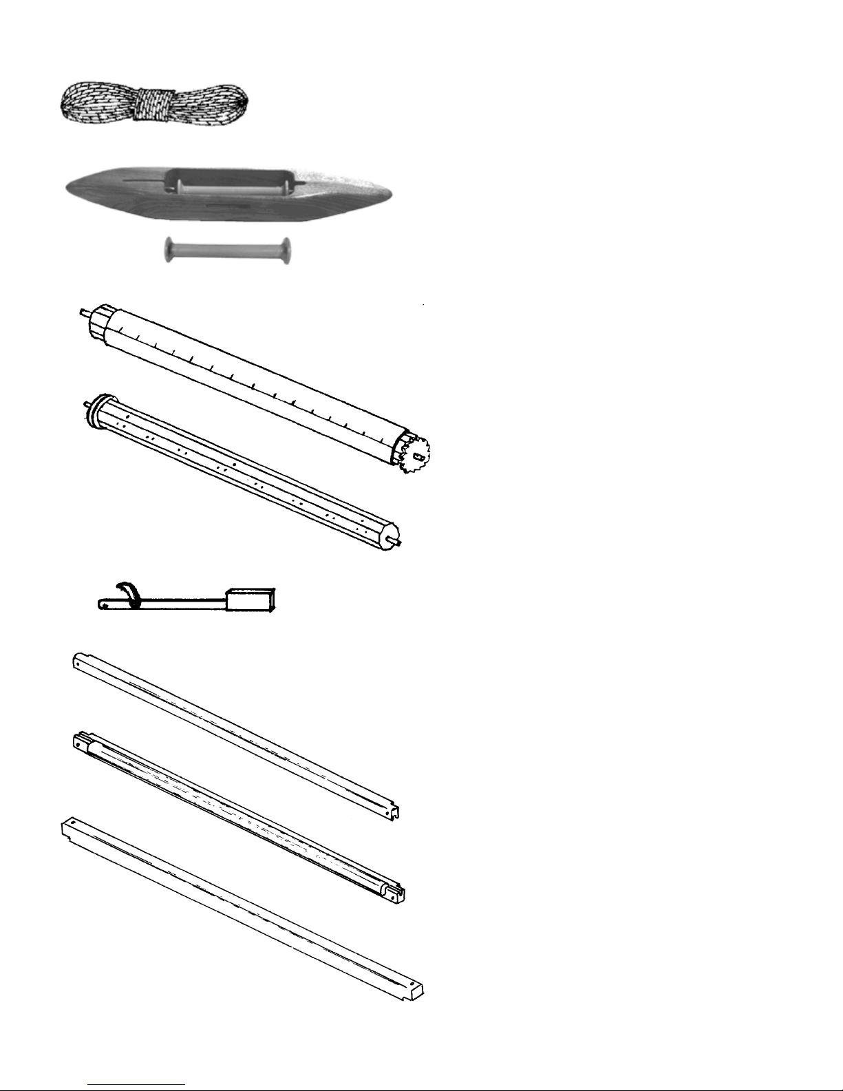
1 PK. 10 YDS FOR BEAM STICK
1 PK 5 YDS FOR BEAMING AND LEASE
STICKS
1 SHUTTLE
1 DOZ. BOBINES 4"
1 CLOTH BEAM WITH RATCHET
WHEEL (wood = 38 1/8")
1 WARP BEAM WITH BRAKE DRUM
(wood = 38 7/8")
1 TAKE-UP MOTION HANDLE
1 BATTEN HANDTREE
1 BATTEN SLEY WITH SHUTTLE RACE
2 BREAST BEAMS
3
(back part)
Note for Leclerc in French: La
planche avant et arrière de la
boite à marmousset doit avoir
les vis pour cordes à bascule
et ressort à pédale
2 X 10 vis #12 x ¸¾”
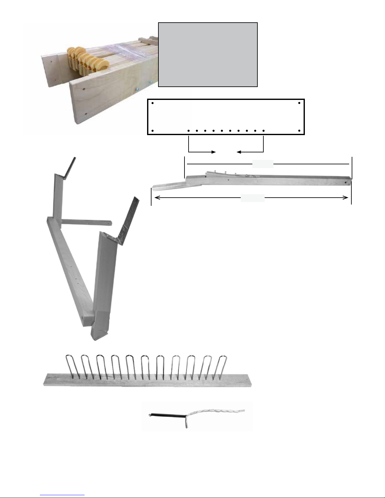
20 3/8"
36 1/8"
1 JACK BOX
(DO NOT REMOVE THE
TAPE UNTILL IT IS
INSTALLED IN THE LOOM)
31¼"
10 treadles with rocker piece
1 stabilizing post cross member
assembly with 2 stabilizing
back posts
1 Treadle Separator 40” long
10 Treadle springs with
Loop cords 9”
4
10.5"
10.5"
8 SHAFT (harness) FRAMES
1 REED
2 LEASE STICKS
1 BEAM STICK
3 WARP RODS
1000 HEDDLES
1 HEDDLE AND REED HOOK 8 5/8” long
6140-9000
1 Black Screwdriver
1 Red Screwdriver
1 Adjustment wrench
10 treadle hooks 10”
10 pegs to lock the treadle hooks
60 TREADLE CORDS 6½”
1 CRANK FOR BACK BEAM
5
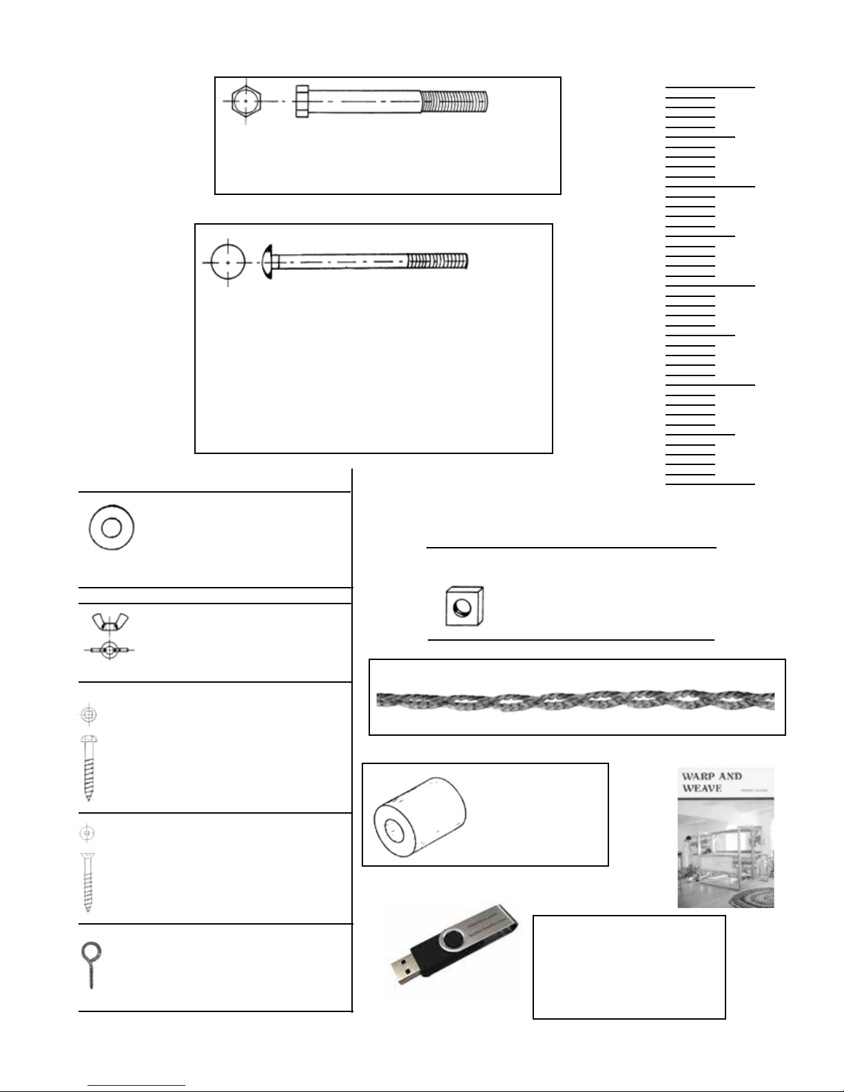
Machine bolts
1X 7/16 X 3½" (12 mm X 90 mm)
0
1"
Carriage Bolts
2 - ¼ X 3¼” (6 mm x 80 mm) (F. Cross-Member)
2 - ¼” X 3” (6 mm x 75 mm) (Treadle blocs)
2 - ¼” X 1¾” (6 mm x 45 mm)
4 - 5/16 X 2½” (8 mm x 65 mm)
2 - 1/4” X 2¼” (stab. hook)
1 - 9/16 cloth beam
2 - 9/16” treadle set
4 - 5/16” (8 mm)
5 - ¼" (6 mm)
Wing nuts
6 X - ¼” (6 mm)
2X - 5/16” (8 mm)
2"
3"
4"
SQUARE NUTS
2 - ¼” (6 mm)
2 - 5/16” (8 mm)
10 Loop cords 18½” long for treadle rocker
Round head screws
6 - #14 X 2” (50 mm)
2 - #8, 1¼” (treadles separator)
8 - #12, 1½” (jack box)
6 - #8, 1” (stab. post hinges)
6 - #14, 2½" (base)
Flat head screws
4X - #12 X 1½” (38 mm)
(castle top)
2X eye screws
1½”
9x Wooden spacers
Instruction Video
showing all stages of the
installation.
6
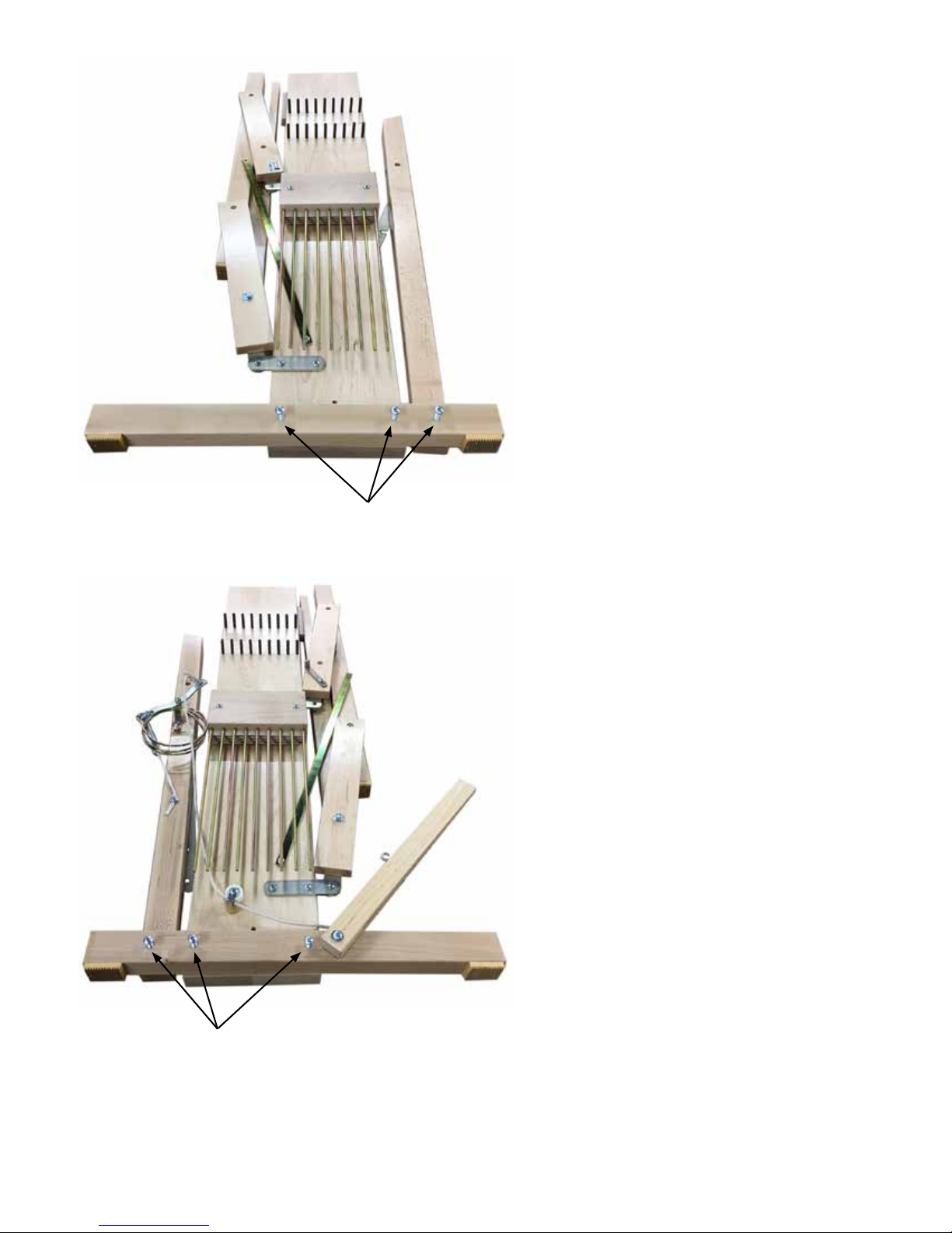
#14 round head screw 2½"
Lay the left side on the oor with
caution (you can put a piece of
cardboard on the oor). Removed
the packing material and using
three #14 round head screw 2½",
afx the base to the left upright
and the back post to the base.
#14 round head screw 2½"
Lay the right side on the oor with
caution (you can put a piece of
cardboard on the oor). Removed
the packing material and using
three #14 round head screw 2½",
afx the base (the brake treadle is
already installed) to the right upright and the back post to the base.
7
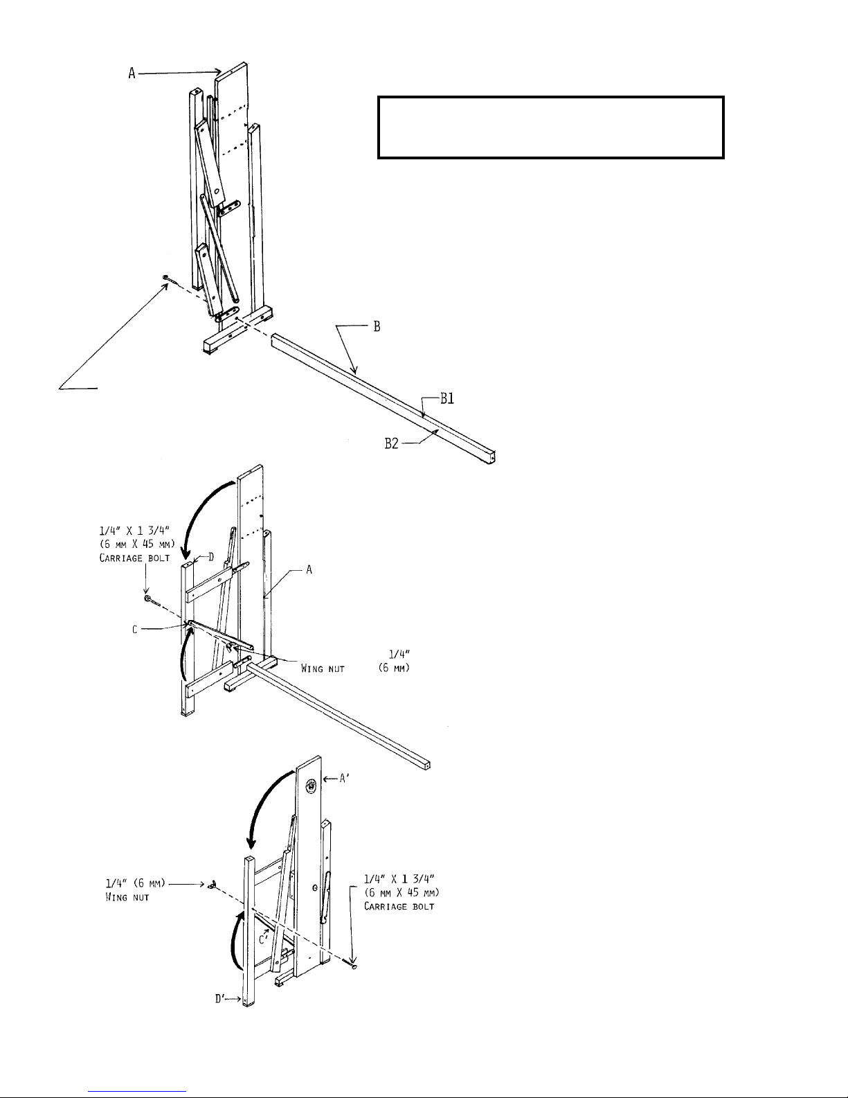
ATTENTION: Application of soap to the
screws will make their insertion easier.
Place right-hand side A straight up beside the
wall.
Using a 2” (50-mm) round-headed screw no 14,
afx lower middle cross-member B to the bottom of left-hand side A.
The lower middle cross-member has a hole at
either end; the narrow sides B1 must be above
and under the cross-member and the wide faces
B2 must be on the sides.
Unfold the front section of left-hand side A. Using
a ¼” x 1¾ (6mm x 45mm) carriage bolt and a ¼”
(6mm) wing nut, afx metal hook C to left-hand
side front post D.
Using a ¼” x 1¾” (6mm x 45mm) carriage bolt
and a ¼” (6mm) wing nut, afx metal hook C’ to
right-hand side front post D’.
8
 Loading...