

Page 1
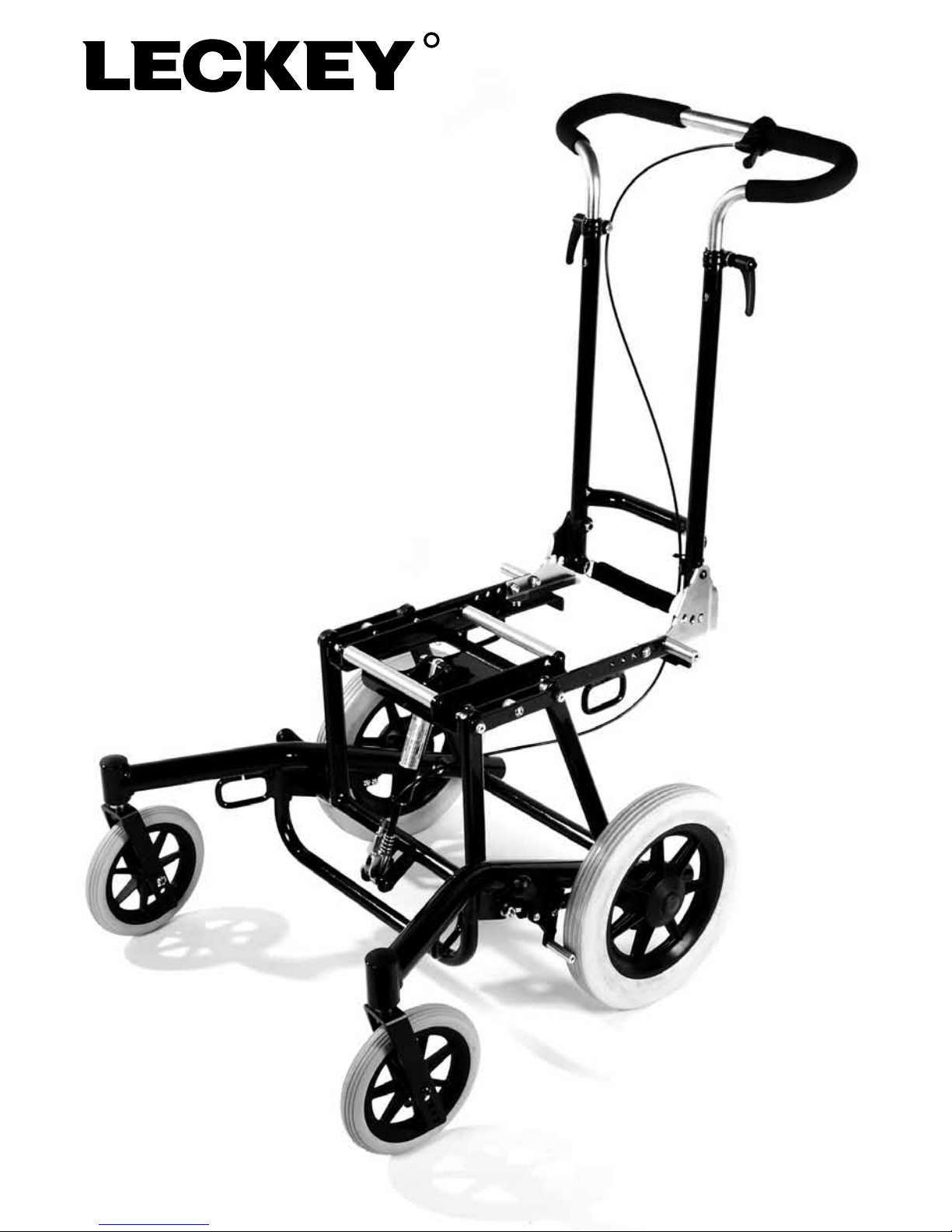
Leckey Tour Mobility Base
User Instructions
Page 2
Page 3

This manual contains information
regarding the use of the Leckey
Tour Mobility Base including its
use for transportation in motor
vehicles. Please read the full
manual to gain the full benefits
offered by this product.
Contents
01 Intended Use
02 Declaration of Conformity
03 Terms of Warranty
04 Product History Record
05 Product Training Record
06 Safety Information
07 Delivery/Preparation
08 Adjusting the mobility base
09 Accessories
10 Maintenance, cleaning and care
11 Instructions for securing the Leckey Tour Mobility Base in a vehicle
12 Crash Test
13 User Restraint Systems
14 Technical Data
Page 4

1. Intended Use
The Leckey Tour Mobility Base is
designed for use with seating systems
intended for a single user. The mobility
base is designed to be suitable for use
indoors and/or outdoors. It is designed to
provide mobility for persons with disability.
It must be adjusted by an orthopaedic or
rehabilitation dealer to integrate with the
seating system being used.
2. Declaration of Conformity
James Leckey Design Ltd as manufacturer
with sole responsibility declares that the
Leckey Seating and Mobility Systems
conform to the requirements of the
93/42/EEC Guidelines, Medical Device
Regulations 2002 and EN 12182 Technical
aids for disabled persons and test
methods.
3. Terms of Warranty
The warranty applies only when the
product is used according to the
specified conditions and for the intended
purposes, following all manufacturers’
recommendations (also see general terms
of sales, delivery and payment). A two
year warranty is provided on all Leckey
manufactured products and components.
4. Product History Record
Your Leckey product is classified as a
Class 1 Medical Device and as such
should only be prescribed, set up or
reissued by a technically competent
person who has been trained in the use
of this product. Leckey recommend that
a written record is maintained to provide
details of all set ups, reissue inspections
and annual inspections of this product.
5. Product Training Record
(Parents, Teachers & Carers)
Your Leckey product is classified as a
Class 1 Medical Device and as such
Leckey recommends that parents,
teachers and carers using the equipment
should be made aware of the following
sections of the user manual by a
technically competent person:
Section 6
Safety Information
Section 9
Instructions for Securing the Mobility Base
in a Motor Vehicle
Page 5

1. Please read the instructions for use
before using this product.
Familiarise yourself with the mobility base
and your chosen seating system on level
ground to avoid potentially dangerous
situations.
2. Park the mobility base on level ground
wherever possible. If parking on a slope is
unavoidable ensure the anti-tipper is in a
functional position.
3. When reaching for objects in front, to
the side or behind the occupant make sure
the occupant does not lean too far out of
the seating system as this may cause the
mobility base to tilt or tip over.
4. Treat your mobility base with care. Do
not drive into or against obstacles without
slowing down.
5. The anti-tipper is designed to prevent
the mobility base with user from tipping
over backwards. The anti-tipper should
not be used to support the base with rear
wheels removed.
6. Do not go up or down stairs without
assistance from another person. If
available make use of ramps and lifts.
In the absence of a ramp or lift, then 2
people should carry the base with seating
system over the obstacle. If only 1 helper is
available, the anti-tipper (if fitted) should be
adjusted or removed as to not contact the
steps, therefore avoiding a potential fall.
Replace anti-tipper afterwards.
7. When lifting the mobility base,
ensure that it is held by firmly attached
components and not by loose or moving
parts.
8. Ensure height adjustable push handle
clamping levers are firmly tightened.
9. Ensure brakes are applied when
stationary on uneven ground and during
transfer.
10. Ensure any tilt and brake cables do not
interfere with any moving parts e.g. wheels.
11. Occupants should be secured with
suitable safety straps, belts or harnesses
at all times.
12. In some combinations of settings
the foot supports may interfere with
the castors. In this case adjust the
settings so that this does not happen as
the manoeuvrability of the base will be
impaired.
13. When using the mobility base in public
areas and streets, ensure local traffic
regulations are observed.
14. Be careful when adjusting the seat
base to avoid finger injuries.
15. Maximum load capacity including
seating system is 110Kg.
16. Ensure that screws are tightened after
adjustment.
6 Safety Information
Page 6

Delivery/
Preparation
7
Contained in the box will be –
Leckey Tour Mobility Base
Instructions for use
Tools required
Accessories as ordered
Page 7

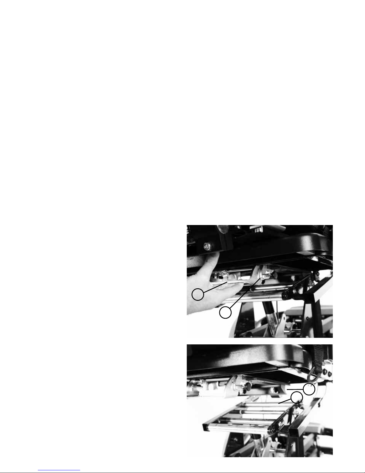
7.2 Handle bar depth
The mobility base will arrive with the handle bar
fitted in a position likely to be suitable for the
seating system to be attached to it. In order to
adjust the position of the handle bar, please
refer to Fig 2.
Remove the 2 screws (A), 2 lap belt posts (B)
and nuts (C) retaining the handle bar assembly
and slide it forward or backwards as desired.
Refit the attachment screws, posts and nuts.
Ensure all nuts & screws are re-tightened to
ensure the handle bars are firmly attached to
the base.
The lap belt posts and screws can be fitted
in either the forward or rearward position,
ensuring the angle of the lap belt is correct (Fig
3) and it does not interfere with any parts of the
base throughout its range of tilt.
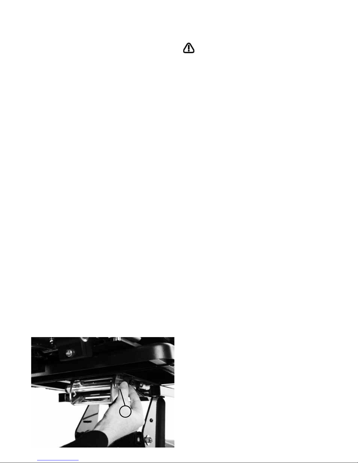
7.1 Seating Interface
The mobility base will arrive with the interface
fitted in a position likely to be suitable for the
seating system to be attached to it. There are
five mounting positions to choose from. The
foremost three positions are suitable for the
Keat Seat and the rearmost are suitable for
the Mygo Seat. In order to adjust the position
of the interface, please refer to Fig 1a and 1b.
Remove the 4 screws (A) and nuts (B)
retaining the interface and slide the interface
forward or backwards as desired. Refit the 4
screws and nuts. Ensure all screws & nuts are
re-tightened to ensure the seating system will
be firmly attached to the base when fitted.
A
B
C
B
A
Fig 2
Fig 3
Fig 1a
Fig 1b
A
B
B
A
Page 8
Refer to Section 9
7.3 Fitting of accessories
To mount the Kit Seating System on the
mobility base release the safety locking pin at
the front of the seat by pulling the pin (A) out
and rotating it through 90 degrees. Carefully
tilt the seat and place it onto the chassis,
locating the channel (B) at the rear of the seat
over the tube at the back of the chassis (C).
Pull the handle (D) at the front of the seat
unit up and then pivot the seat down.
Once the seat is fully lowered, release the
handle and push it forward to ensure it has
fully engaged on the front tube. Rotate the
safety locking pin (A) so that it engages in the
front of the handle.
7.4 Mounting of the
seating system
A
D
B
C
Page 9
To mount the Mygo Seating System on the
mobility base first release the safety locking
pin at the front of the seat. To do this pull
the pin out and rotate through 90 degrees.
Carefully lift the seat and place it into the
chassis. At the rear of the underside of the
seat you will see a receiving channel. Place
this securely over the tube towards the back
of the chassis. Pull the handle at the front
of the seat unit up and then pivot the seat
forward and down. Once the front of the
seat is lowered fully, release the handle and
push it forward to ensure it has fully engaged
on the front tube. Rotate the safety locking
pin so it engages in front of the handle. If it
hits the handle then the seat is not inserted
properly. Remove and repeat process
outlined above.
Once the seat is mounted, ensure that the
static stability of the product is checked. If
the stability is less than 10˚ the user and/
or attendant need to be informed using a
clear warning note, to allow them to take
precautions in interest of the user’s safety.
A
Page 10

Adjusting
the
mobility
base
8
Page 11

8.1 Seat Tilt
The seating system mounting can be tilted
to the rear by approximately 30˚ (Fig 4). This
is achieved by pressing the tilt release lever
(Fig 5). When the desired angle is reached,
release the lever.
Fig 4
Fig 5
Page 12

8.2 Handle bar height
The handle bar can be adjusted to a height
that is suitable for the person pushing the
seat. In order to adjust the height of the
handle bar, please refer to Fig 6.
Loosen the clamping levers (A), Move the
bars to the required height and re-tighten
the clamping levers. The adjustment range is
approximately 230mm. When the handle bar
has reached its maximum height, a popper
will engage in the handle bar outer tube (Fig
7, Item B). Press the popper in once the
clamping levers are loose, while adjusting the
height of the handle bar.
Note - It is recommended that the handle
bar is not adjusted beyond the height at
which the popper engages.
A
A
B
Fig 6
Fig 7
Page 13

8.3 Handle bar angle
The handle bar can be adjusted to an angle
from 90˚ to 120˚ dependant on the desired
back angle of the seating system attached
(fig 8a). In order to adjust the angle of the
handle bar, please refer to Fig 8b.
Pull the lock strap (A), this will release the
locking pins (B) either side of the handle bar.
Adjust the handle bar angle then release the
lock strap. Ensure both locking pins engage
in the locking plate holes (C) after adjustments
are made.
C
B
A
Fig 8b
Fig 8a
Page 14

To operate the friction brakes on a 12” wheel
application, please refer to Fig 9. To operate
the drum brakes on a 22” and 24” wheel
application, please refer to Fig 10.
To apply the friction brake, push the brake
lever (A) forward. To release the friction brake,
push the brake lever rearward. To apply the
drum brake, squeeze the brake lever (B). To
lock the drum brake, squeeze the brake lever
(B) and engage the retaining claw (C) with
your index finger. To unlock the drum brake,
squeeze the brake lever slightly and the
retaining claw will disengage.
Check the brakes weekly to ensure they
are operational and adjust if necessary
(Refer to section 10, ‘Maintenance,
cleaning and care’).
A
C
B
Fig 9
Fig 10
8.4 Brakes
Page 15

Accessories
9
Page 16

9.1 Anti-tippers/Tip assist
The anti-tippers prevent the mobility base
from tipping too far backwards. Please refer
to Fig 11a and 11b.
To fit the anti-tipper for the first time, press
down the popper (A) and slide into the chassis
tube at the rear of the mobility base.
The effectiveness of the anti-tipper is
achieved by adjusting its position. Press the
popper (A) then slide the anti-tipper to the
desired position, ensuring the popper has
engaged in one of the locking holes (B).
The further out the anti-tipper, the more
effective it is.
In order to make tipping the mobility base
easier to clear an obstacle e.g. curbs, tipping
assistance can be achieved by simply
stepping onto the anti-tipper tubes while
pulling back on the handle bar.
Note - To avoid an accident risk, it may be
necessary to adjust the anti-tipper inwards to
clear an obstacle. In some circumstances it
may be necessary to remove the anti-tipper
completely. This is done by pressing in the
popper (A) and sliding the anti-tipper out
completely. Once the obstacle has
been negotiated, re-insert the anti-tipper
ensuring the popper has engaged in one of
the locking holes.
In the event anti-tippers are fitted or
removed, please inform the occupant if
they do not require an attendant.
B
A
Fig 11a Fig 11b
Page 17

9.2 Spoke protectors
In order to reduce the risk of injuries to
the occupant’s fingers, the use of spoke
protectors is encouraged. See fig 12.
To fit the spoke protectors, place it over
the face of the wheel, lining up the hand
rim support posts to the scallops (A) on the
outside edge of the spoke protector. Place
the supplied clips through the slots in the
spoke protector and clip to the spoke directly
behind the slot (B).
B
A
Fig 12
Page 18

9.3 Rear wheels
The rear wheels are available in 3 sizes,
300mm[12”] (Fig 13), 560mm[22”] or
610mm[24”] (Fig 14). The larger 2 sizes are
provided with a quick release axle (Fig 15)
so the wheels can be removed quickly, if
necessary. To fit the wheel, simply press and
hold the centre button (A) and push the wheel
and axle fully on the hub. Ensure the wheels
are fully secure before using the mobility
base. Removal is the reversal to fitting.
A
Fig 13
Fig 14 Fig 15
Page 19

9.4 Front castors
The front castors are available in 3 sizes,
100mm[4”] (Fig 16), 150mm[6”] (Fig 17) and
200mm[8”] (Fig 18). These can be chosen
dependant on the use of the mobility base
and the clearance that is required for the foot
plates of the seating system.
Fig 18Fig 16
Fig 17
Page 20

Maintenance,
cleaning
and care
10
Page 21

10.1 Annual Product
Inspection
The correct function of the mobility base and
seating system should be checked before
every use. The table of checks listed below
are to be carried out by the user at the
intervals shown. Failure to carry out these
checks may lead to problems arising that
could invalidate the warranty.
Check Weekly Monthly
Brake/Wheel lock function
Security of seating system
Firm attachment of wheels
Firm attachment of handle bar
Bearing contamination
Screw connections
Visual examination of wearing parts (e.g. Tires, bearings)
Spoke tension if 22” or 24” wheels are used
Should any defects become apparent,
please contact an authorised dealer.
It is also recommended that your mobility
base is serviced every 12 months by an
authorised dealer.
Page 22

10.2 Adjustable Brake
Force for 12” wheel
To adjust the friction brake, please refer to
Fig 19a and 19b.
By reducing the distance between the
wheel lock friction post (A) and the wheel,
braking force is increased. In order to adjust
the brake, loosen the nuts (B), allowing the
wheel lock to slide. The wheel lock should be
adjusted so that when the wheel lock is not
activated, the distance between the wheel
lock friction post (A) and the tyre is 10mm.
After adjustment tighten the nuts (B). Ensure
the wheels lock when the brake is activated
after adjustment.
Ensure the locking/braking forces of both
wheels are adjusted equally.
B
A
Fig 19bFig 19a
Page 23

10.4 Cleaning and care
To clean your mobility base, use a mild
detergent. It is important to pay particular
attention to certain components of your
mobility base to ensure a smooth operation.
Hair or dirt particles may accumulate between
the castor wheel and the fork, making it
difficult for the castor wheels to rotate.
Remove hair and dirt particles.
When mounting or removing the wheels,
please ensure no oil gets on the brake linings
or brake drum.
If the mobility base gets wet, towel dry it as
soon as possible.
Do not use the mobility base in salt water.
Keep sand or other particles from damaging
wheel bearings.
Check the tightness of all screw connections
regularly. If a screw connection frequently
comes loose, consult your dealer.
10.3 Adjustable Brake
force for 22” and 24” wheel
To adjust the drum braking force, please refer
to Fig 20.
The braking force can be adjusted using
the adjustment screw (A). By unscrewing
the adjustment screw, braking force will be
increased and vice-versa. With the wheel
rotating freely the adjustment screw should
be unscrewed until you can hear the noise
of the wheel being braked. Next screw in
the adjustment screw until the friction noise
disappears. The wheel should run freely. After
adjustment tighten the locking nut (B) against
the post (C). When tightening the locking
nut (B), ensure that the adjustment screw (A)
doesn’t rotate. Ensure the wheels lock only
when the retaining claw (Fig 10, item C) of the
hand brake lever is in the 2nd or 3rd ratchet
position.
Ensure the locking/braking forces of both
wheels are adjusted equally.
A
B
C
Fig 20
Page 24

11 Instructions for securing
the Leckey Tour Mobility
Base in a vehicle
These instructions apply to the Leckey
Tour Mobility Base only. For all other
mobility bases please refer to the
manufacturer’s instructions.
The wheelchair user must be seated in
an upright seating position in the seating
system.
Place the Leckey Tour Mobility Base in a
forward facing direction, centrally between
the tie-down rails on the floor of the vehicle,
then apply the brakes.
Loose parts must be secured separately in
the motor vehicle.
Check that the vehicle anchored restraint
system and the wheelchair restraint system
comply with the appropriate Standard.
Rotate the front wheels of the Leckey Tour
Mobility Base so that they are in a forward
facing direction in order to improve stability
of the unit (Fig 21).
The mobility base must be anchored to the
vehicle using tie-down straps. Ensure that
one end of the tie-down straps are securely
attached to the floor tracks. Attach the other
ends of the straps to the anchor points on
the Leckey Tour Mobility Base on the left/
right sides of the front frame (A) and at the
left / right sides of the rear frame (B). Refer to
figures 22a and 22b.
Fig 21
Fig 22a
Fig 22b
B
A
A
B
Page 25

The tie down straps must be tightened
firmly in accordance with the manufacturer’s
specifications.
Note: The maximum angle of the front
tie-down straps (1) must be 60° and the
maximum angle of the rear tie-down straps
(2) must be 45° (Fig 23).
The vehicle restraint system’s pelvic belt
and shoulder harness must be attached
in accordance with the manufacturer’s
specifications and tightened as firmly
as possible.
If your seating system does not include
them and there is more than 30cm of space
in front of the occupant’s feet, then it is
recommended that leg restraints be used to
keep the user’s legs from extending.
Always ensure that restraint belts are
close to the body and are not distanced
from user’s body by components such as
armrests or wheels.
Fig 23
Page 26

12 Crash test
The Leckey Tour Mobility Base has been
crash tested facing forwards, with an Unwin
Restraint System, pelvic harnesses and chest
harnesses. Please see individual product
User Instructions for further details.
Leckey does not recommend the use of
a mobility base with a seating system
for transportation in a motor vehicle. Our
seating and mobility systems are designed
to be easily manoeuvrable, lightweight
and functional, which can conflict with the
requirements which a seat must fulfil for
transport in a motor vehicle. Furthermore
the incorrect use of additional wheelchair
tie-down systems and occupant restraint
systems may result in an increased safety
risk, which is not the case when using the
vehicle with anchored restraint systems
(seatbelts, headrest, airbags etc.). Leckey
highly recommend, whenever possible,
that the mobility system users transfer to
the seats installed in the motor vehicle and
use the corresponding vehicle restraint
systems. In the event of a motor vehicle
collision, Leckey cannot be held responsible
for any injury caused to the users of Leckey
products, if the occupant’s restraint and tiedown system has not been correctly applied.
An independent pelvic and shoulder
harness should be applied as the user’s
restraint system. The harness must
conform to the standards described in
section 13. If independent harnesses
are not used, an independent vehicleanchored 3 point occupant belt restraint
system must be used instead.
The 4 point tie-down straps used to
secure the mobility base to the vehicle
must conform to the standards listed in
section 13 and be compatible with the
attached brackets on the mobility base.
Wheelchair mounted accessories,
such as trays, respiratory equipment
or communication devices should
be removed and secured elsewhere
during transport. It should be noted that
Leckey’s products have been crash tested
without the accessories being mounted
and Leckey therefore can accept no
accountability for any injuries, should the
vehicle be involved in an accident.
If the Leckey product is involved in
a crash it must no longer be used
for the transport of the occupant(s).
We recommend that the product be
returned to Leckey for assessment or
replaced immediately. The reason for the
immediate replacement is due to the fact
that sudden stops or impacts during the
accident could structurally damage the
mobility base and seating system.
Page 27

The mobility base should only be used in
motor vehicles in a forward-facing seating
position.
The mobility base should only be used
with seating systems which have
passed crash testing, if being used for
transportation in a vehicle.
The mobility base should only be used for
transportation in a motor vehicle fitted
with anchor brackets, which comply with
National and International standards.
The person responsible for the
transportation of the individual in the
mobility base is also responsible for their
safety.
Alterations must not be made to the frame
or structural parts of the Leckey product.
If the mobility base is enabled with back
angle adjustment or tilt in space, the
user must be sitting fully upright during
transportation. If this is not possible
due to the user’s condition a full-risk
assessment should be undertaken to
address the issue of the user’s safety.
During transportation, you must ensure
that there are clear zones around the
mobility base and wheelchair user, as
shown in Figure 24: 650 mm at the front,
when the 3-point shoulder and pelvic belt
occupant restraint is used, and 400mm
at the rear. The required overall height
from the floor is between 1250 mm and
1550mm, depending on the height of the
user.
Fig 24
Page 28

13 User restraint systems
User restraints must conform to the following
standards for transportation in a motor
vehicle/ guidelines:
WTRS: Wheelchair
tie-down and
occupant restraint
system
International
ISO 7176-19
ISO 10542
Page 29

14 Technical Data
Front Castor Diameter
Wheelbase
100mm / 4”
420mm / 16.5”
150mm / 6”
425mm / 16.7”
200mm / 8”
430mm / 16.9”
Configured for: Mygo or KIT
Seat Tilt
Minimum Height When Folded
Push Handle Angle
Push Handle Height
Seat Base Height
Max Combined Weight of
User and Seat
110kg
242.5lbs
450mm
17.7”
1050-1280mm
41.3-50.4”
90°-120°
570mm
22.4”
0-30°
Configured for: Mygo
KIT
30.5cm / 12” 30.5cm / 12”56cm / 22”
61cm / 24”
56cm / 22”
61cm / 24”
Rear Wheel Diameter
23kg
50.7lbs
23kg
50.7lbs
27kg
59.5lbs
27kg
59.5lbs
Chassis Weight
500mm
19.7”
500mm
19.7”
515mm
20.3”
570mm
22.4”
Space Between Wheels
790mm
31.1”
1665mm
65.6”
790mm
31.1”
1665mm
65.6”
645mm
25.4”
645mm
25.4”
850mm
33.5”
1712mm
67.4”
850mm
33.5”
1785mm
70.3”
690mm
27.2”
645mm
25.4”
Overall Width
Overall Length Without Seat
Turning Radius
Page 30

14 Technical Data continued
Turning Radius
To calculate the turning
radius around a braked wheel,
use the following formula -
W = B + √(A²+B²)
A = overall length
B = overall width
W = turning radius
Example:
133-770 with 22” wheel
A = 850mm, B = 690mm
Turning radius = 1785mm
B
W
A
User age range (years)
Seat Depth (b)
Mygo Size 1 Mygo Size 2 KIT Size 1 KIT Size 2
50kg
110lbs
200-325mm
7.8-12.8"
215-350mm
8.5-13.8"
10kg
22lbs
60kg
132lbs
220-345mm
8.7-13.6"
315-470mm
12.4-18.5"
14.5kg
32lbs
75kg
165lbs
215-370mm
8.5-14.6"
330-510mm
13-20.1"
20.5kg
45.1lbs
75kg
165lbs
215-370mm
8.5-14.6"
330-510mm
13-20.1"
21kg
46.2lbs
3 - 10
270-420mm
10.6-16.5"
360-470mm
14.2-18.5"
8 - 14
350-470mm
13.8-18.5"
460-570mm
18.1-22.4"
12 - 18
360-480mm
14.2-18.9"
500-620mm
19.7-24.4"
16 - adult
410-560mm
16.1-22"
560-675mm
22-26.6"
Max. user weight
Backrest Height (c)
Seat Width (a)
Seat to Footplate (d)
Seat unit weight
Page 31

Page 32

24 hour postural
care for babies,
kids & adults.
Sleeping, Sitting,
Standing, Walking,
Moving, Bathing,
Toileting.
Leckey
19 Ballinderry Road
Lisburn
BT28 2SA
Northern Ireland
United Kingdom
T: 028 9260 0750
E: info@leckey.com
W: www.leckey.com
LS259-03
 Loading...