

Page 1
Mygo Stander
User Instructions
Manuale Standing
Posturale Mygo
Benutzerhandbuch
Mygo Stehständer
Mode d’emploi du
Verticalisateur Mygo
Manual del Usuario
del Bipedestador
Mygo Stander
Page 2
Page 3

Contents
01 Intended use
02 Declaration of conformity
03 Terms of warranty
04 Product history record
05 Product Training
06 Safety Information
07 How to unpack and assemble
08 Fitting the Covers
09 Clinical setup for postural management
10 Frequent adjustments for daily use
11 Cleaning and Care Information
12 Daily product inspection
13 Annual Product Inspection
14 Reissuing Leckey products
15 Product servicing
16 Technical Information
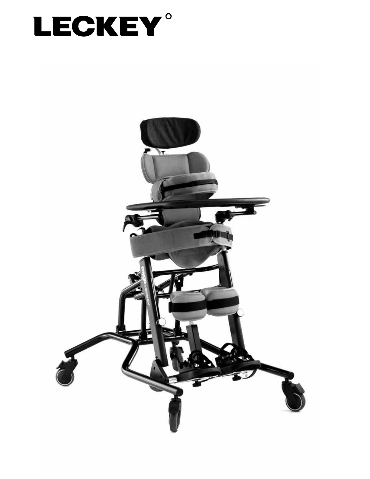
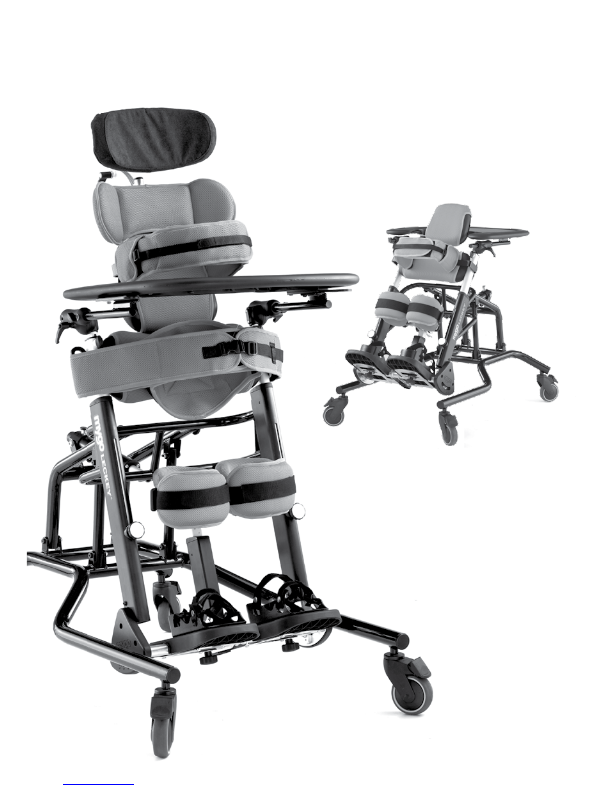
The Mygo Stander can be positioned in prone,
upright or supine, to allow a progressive and varied
standing therapy programme. For use by individual
or multiple children, the Mygo Stander aids and
increases functionality for children of all abilities,
with its intelligent knee supports and dynamic
footplates it can bring standing therapy to children
with fixed knee contractures of up to 25 degrees.
It’s easy and intuitive to use and simplifies the
process of getting your child into a comfortable
and secure standing position. It’s standing made
simple, whilst accommodating a broader range of
complexities. This manual shows you how you can
quickly and easily make use of all of the functions.
The instructions on the safety and maintenance of
the product will ensure that you will enjoy the use of
this product for a long time.
Page 4

1. Intended Use
The Mygo Stander is for use in prone,
supine and upright standing. The Mygo
Stander comes in 2 sizes, size 1 is for kids
aged 4-10 and size 2 is for 8-14 years,
with a maximum user weight of 50kgs
(110lbs) and 60kgs (132lbs) respectively.
2. Declaration of Conformity
James Leckey Design Ltd. as
manufacturer with sole responsibility
declares that the Leckey Mygo Stander
conforms to the requirements of the
93/42/EEC Guidelines and EN12182
Technical aids for disabled persons,
general requirements and test methods.
3. Terms of Warranty
The Warranty applies only when the
product is used according to the
specified conditions and for the intended
purposes, following all manufacturer’s
recommendations (also see general terms
of sales, delivery and payment). A two
year warranty is provided on all Leckey
manufactured products and components.
4. Product History Record
Your Leckey product is classified as
a Class 1 Medical device and as such
should only be prescribed, set up
or reissued for use by a technically
competent person who has been
trained in the use of this product.
Leckey recommend that a written record
is maintained to provide details of all
setups, reissue inspections and annual
inspections of this product.
5. Product Training Record
(Parents, Teachers & Carers)
Your Leckey product is a prescribed Class
1 Medical Device and as such Leckey
recommend that parents, teachers and
carers using the equipment should be
made aware of the following sections
of this user manual by a technically
competent person.
Section 6
Safety Information
Section 9
Clinical Setup for postural management
Section 10
Frequent adjustment for daily use
Section 11
Cleaning & Care Information
Section 12
Daily Product Inspection
Leckey recommend that a written record
is maintained of all those who have been
trained in the correct use of this product.
Page 5
6.1 Always read instructions fully before
use.
6.2 Users should not be left unattended at
any time whilst using Leckey equipment.
6.3 Only use Leckey approved
components with your product. Never
modify the product in any way. Failure
to follow instructions may put the user
or carer at risk and will invalidate the
warranty on the product.
6.4 If in any doubt as to the continued safe
use of your product or if any parts should
fail, please cease using the product and
contact our customer services department
or local dealer as soon as possible.
6.5 Carry out all positional adjustments
and ensure that they are securely fastened
before you put the user into this product.
Some adjustments may require the use
of a tool which is provided with each
product. Keep all tools out of reach of
children.
6.6 When placing the user into the
standing frame, for safety reasons, always
secure the pelvic band first. The chest
and knee straps should then be fastened.
6.7 When used in the supine position it
is important to ensure the knee pads are
fastened securely. Always check the clips
are fully engaged.
6.8 Although the stander is fitted with
castors it is not a mobility device. Always
ensure that the castor brakes are locked
at all times when the frame is in use,
being adjusted or even just stored.
6.9 When adjusting the angle of the
Leckey Mygo Stander ensure that the
user and all parts of the product are well
clear of surrounding furnishings to avoid
potential collisions.
6.10 Fine positional adjustments may be
carried out safely when the user is in the
product. But it is important to support all
pads when adjusting them while the user
is in the product.
6.11 Never leave the product on a sloping
surface greater than 5 degrees. Always
remember to lock all the castors.
6.12 The product contains components
which could present a choking hazard to
small children. Always check that locking
knobs and bolts within the child’s reach
are tightened and secure at all times.
6.13 Leckey products comply with fire
safety regulations in accordance with
EN12182. However the product contains
plastic components and therefore should
be kept away from all direct sources of
heat including naked flames, cigarettes,
electric and gas heaters.
6.14 Never place hot items on the Activity
Tray as they may damage the plastic.
6.15 Clean the product regularly. Do
not use abrasive cleaners. Carry out
maintenance checks on a regular basis to
ensure your product is in good working
condition.
6 Safety Information
Page 6

6.16 The product is designed for indoor
use and when not in use should be
stored in a dry place that is not subjected
to extremes of temperature. The safe
operating temperature range of the
product is +5° to +40° Celsius.
Page 7

How to
unpack and
assemble
7
Your Mygo stander will arrive
flat in a cardboard box. Firstly
remove everything from the box
and check you have all the parts
you have ordered.
Page 8

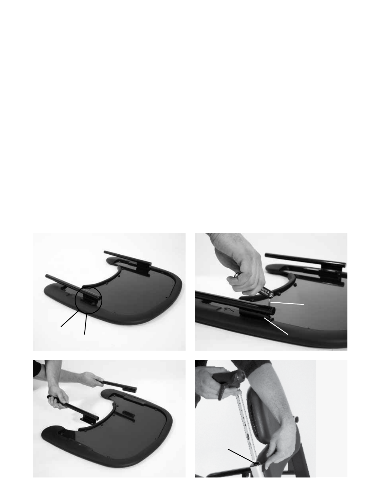
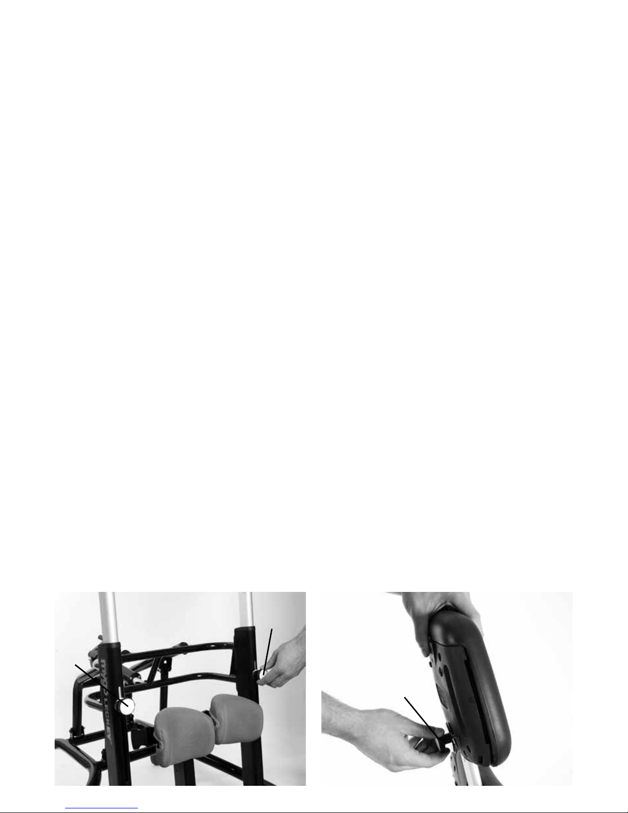
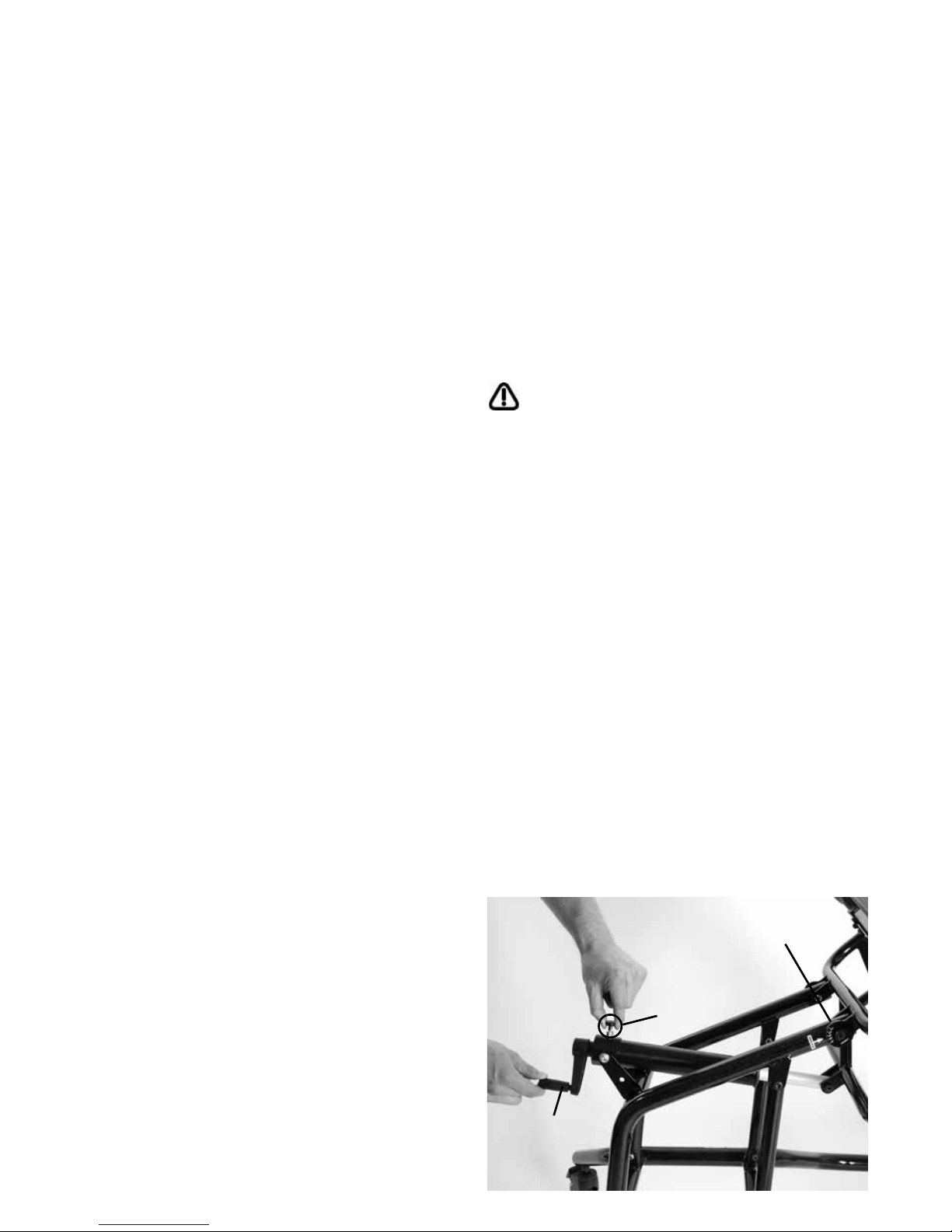
To assemble the product with the stander
upright, lift it up from the cross bar (a), place
vertical tubes in between the free lugs on the
chassis and line up the holes (b) (the groove
in the vertical tube should help with the
location).
Add the bolts and tighten (c). Repeat this
on the other side. Then lift up the manual
actuator to the free lugs on the cross bar and
line up the holes, then add bolts and tighten
(d).
A
C
A
B
D
B
D
Page 9
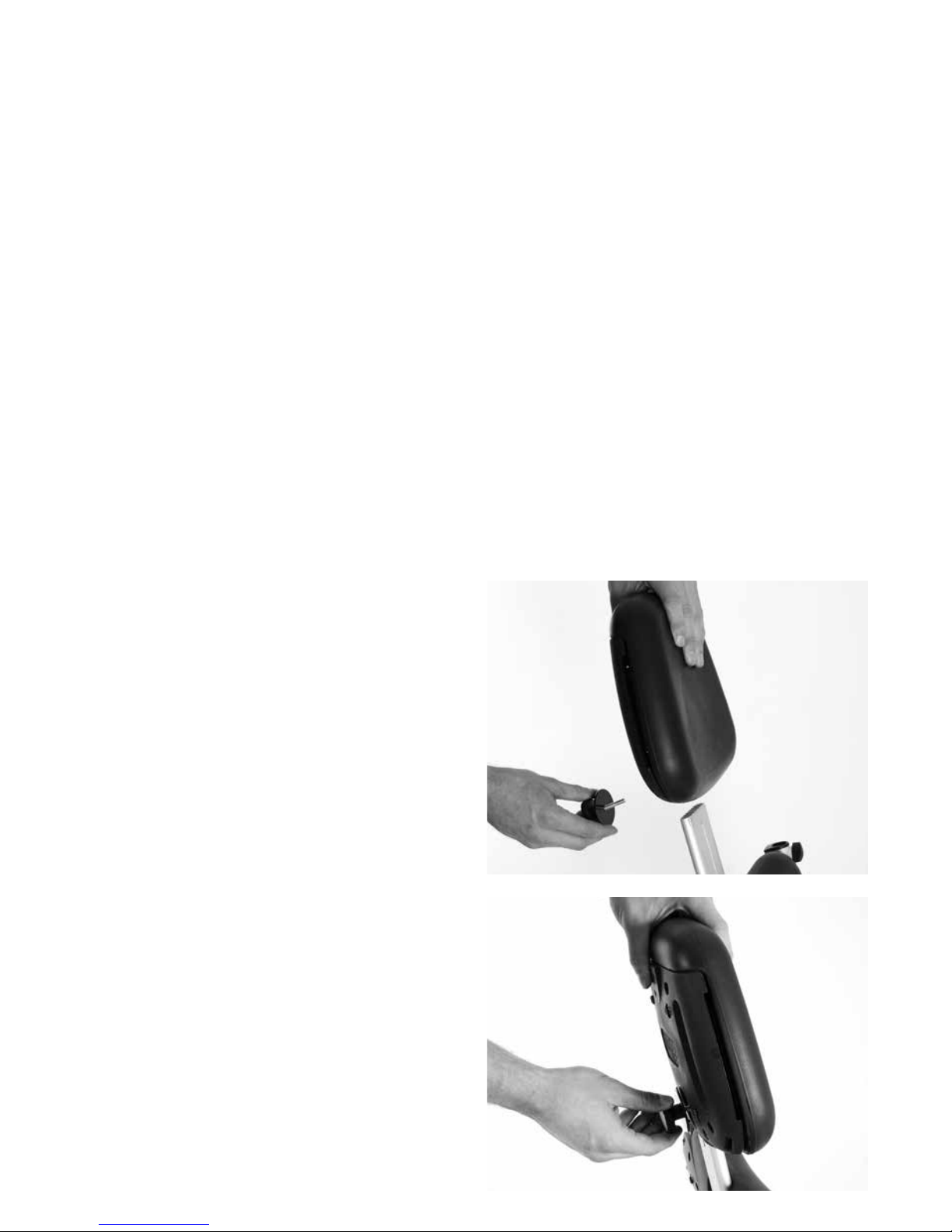
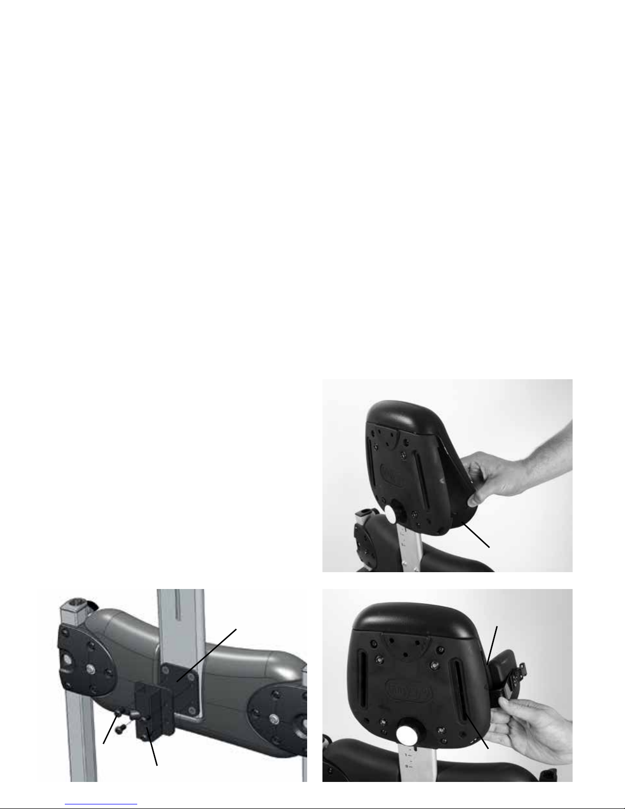
7.2 How to attach the
chest support
Remove the screw on the chest support,
place the chest support onto the metal
extrusion at the required height, replace the
screw and tighten.
7.1 Multi Tool
A number of adjustments will require the use
of a multi tool, which is supplied with each
product.
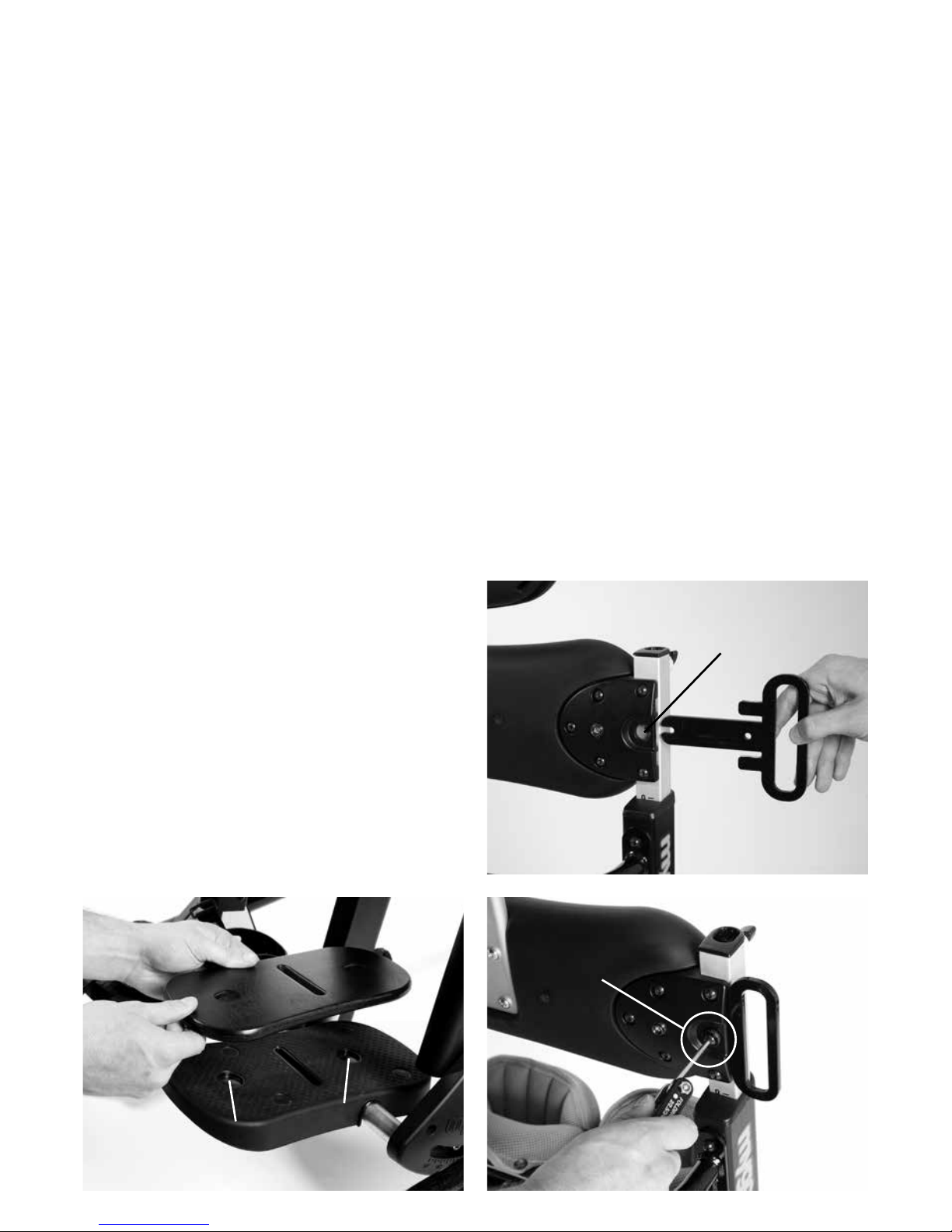
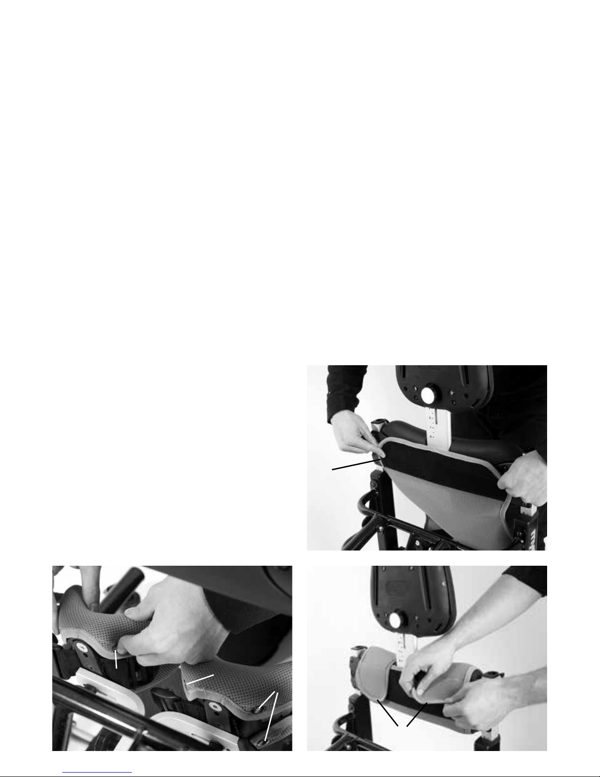
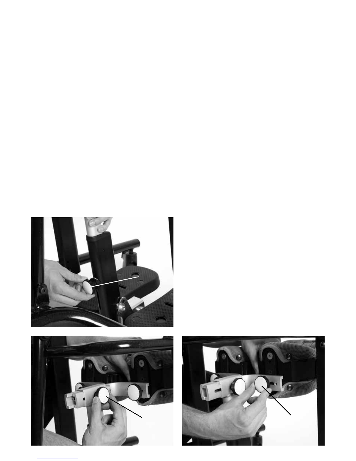
Page 10
Before inserting the tray receivers the clamp
plate for the height adjustment of the tray
must be moved out of the way, as it is
contained in the top of the hip pad extrusion.
To do this; loosen the knob at the top of
the hip pad (f) and push it in, this will push
the clamp plate out of the way of the tray
receiver bar. Then insert the tray receiver
bar into the top of the hip pad extrusion (g),
move it down to the required height and
retighten the knob securely.
Repeat on the opposite side. Now you can
insert your tray by inserting the tray bars into
the receivers to the required depth from the
front for prone and the back for supine then
retighten securely using knob on receiver (h).
B
E
G
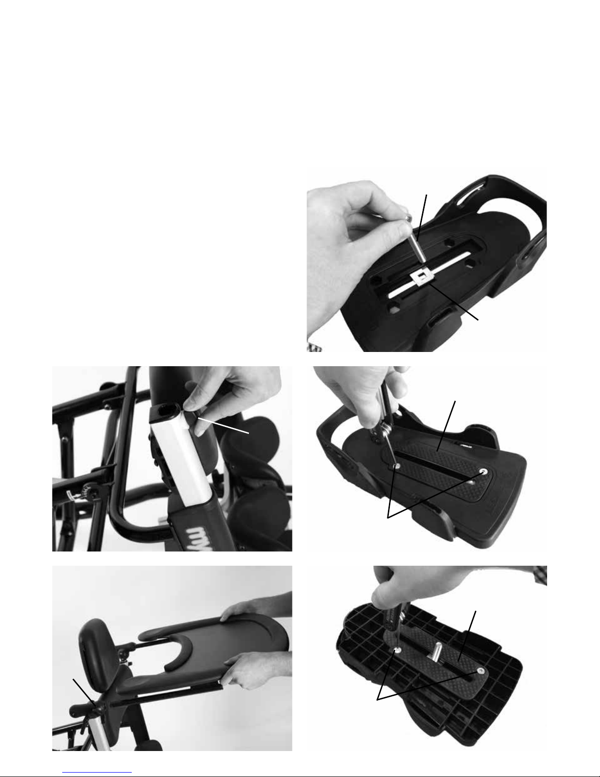
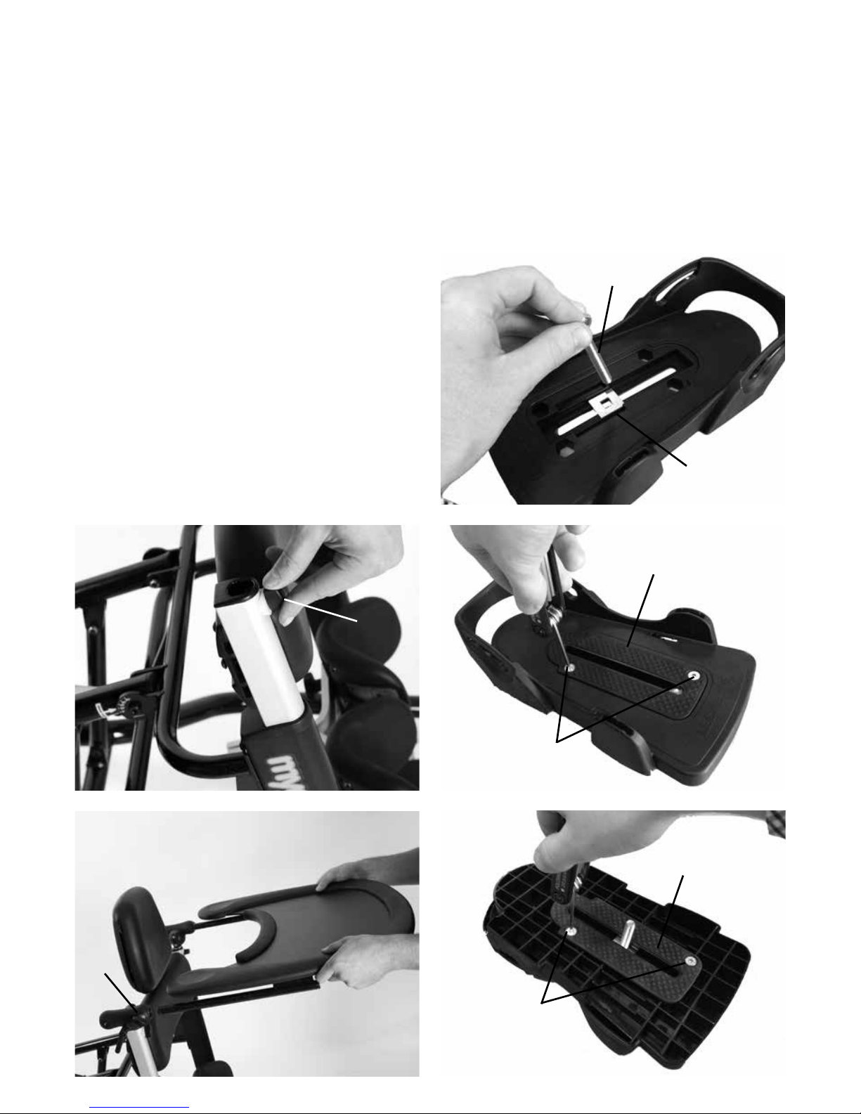
7.3 How to attach the tray
receiver and tray
First of all ensure that your tray is configured
to the size of your stander.
For the Size 1 the brackets on the tray bars
should point outwards (a).
For the Size 2 the brackets on the tray bars
should point inwards (b).
If you need to change the configuration;
remove the Allen bolts (c), swap the bars
over (d) then replace the Allen bolts and
retighten (e).
A
C
D
Page 11
F
H
7.4 Inserting attachment
bolt on Sandals
Insert the required attachment bolt (a)
along with the retention plate (b). Place a
rubber lid (c) on, both, the top and bottom
of the sandal. Fasten using the four screws
(d) provided. To remove or replace the
attachment bolt, reverse this process.
A
1
2
3
B
D
C
D
C
Page 12

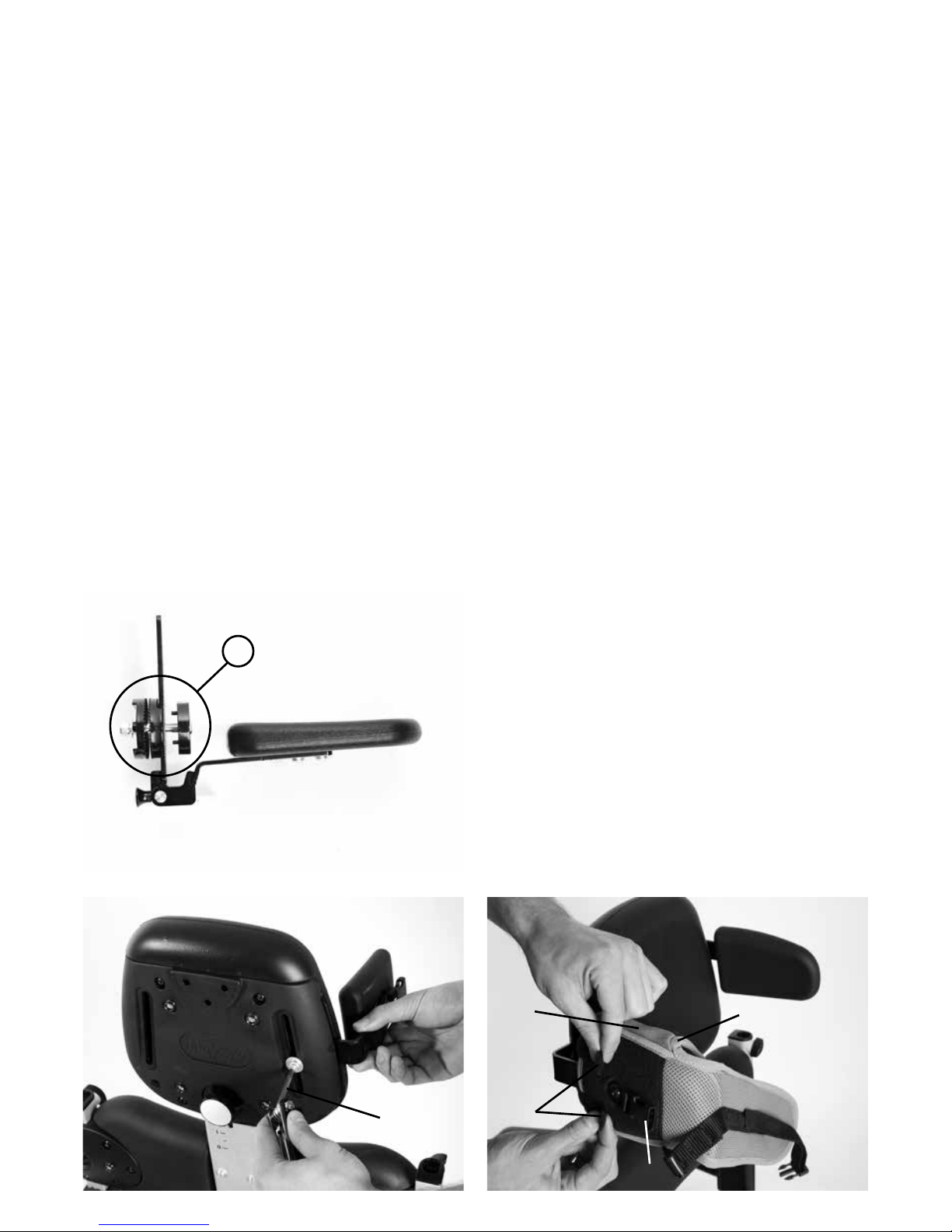
7.6 How to attach the
shoulder support for
supine standing
7.5 Attaching the Sandals
To attach the shoulder support to the stander,
insert the Allen bolt into the bottom hole on
the back of the chest support as shown (a).
Place the shoulder support onto the inserted
Allen bolt and secure with the two further
Allen bolts supplied (b).
Place the sandal so that the attachment bolt
goes through the slot in the footplate. To secure,
on the underside of the footplate place the rubber
washer (a), followed by the metal washer (b) and
then the knob (c) onto the attachment bolt. To
position the sandals, simply loosen the knob
(c) under the footplate, select the position you
require and re-fasten the knob.
A
2
1
C
A
B
C
Page 13
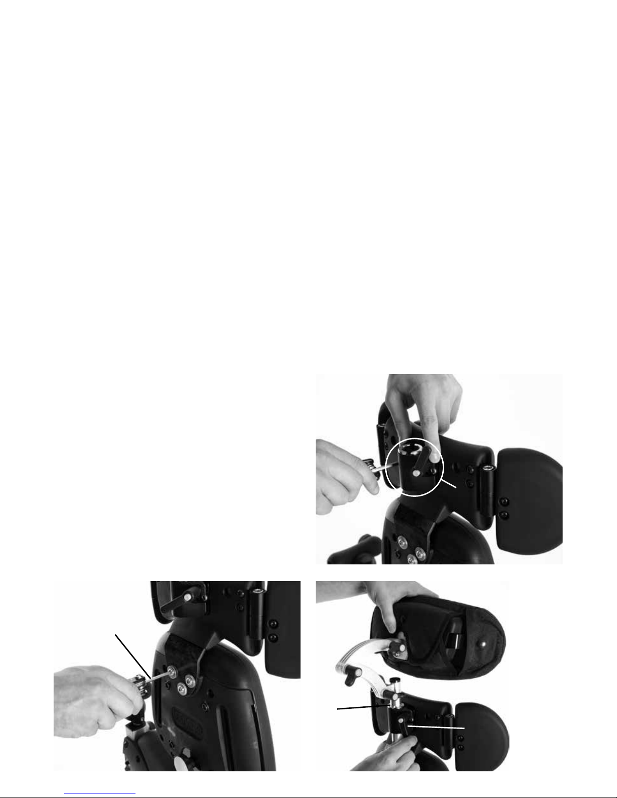
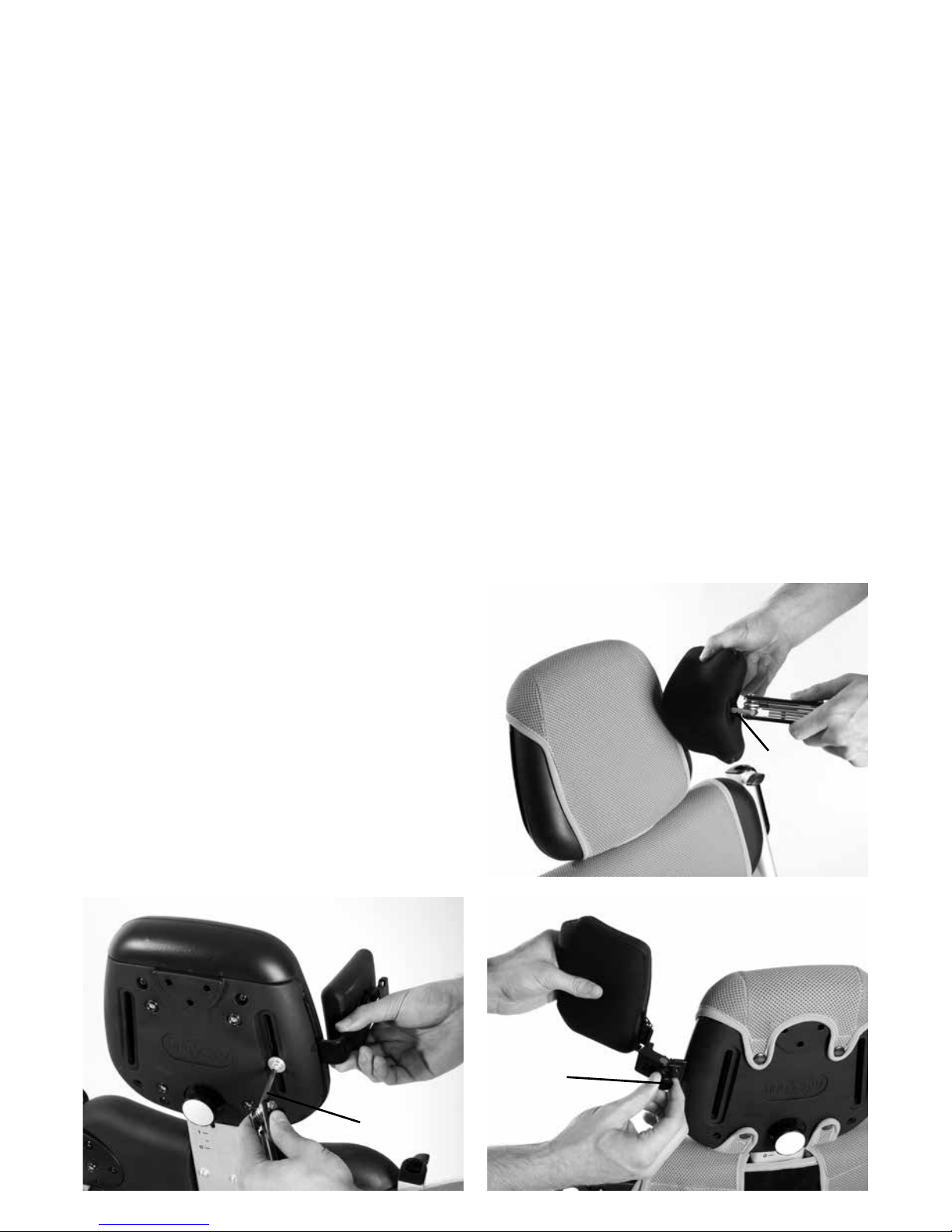
7.7 Attaching the headrest
for supine standing
The head support cannot be used without
the shoulder support for supine standing.
To attach the headrest place the headrest
clamp onto the shoulder support (a) and
secure using the Allen bolts provided. Then
slide the headrest stem into the receiving
bracket (b), set the height required and
secure using the hand lever (c).
A
C
B
B
Page 14
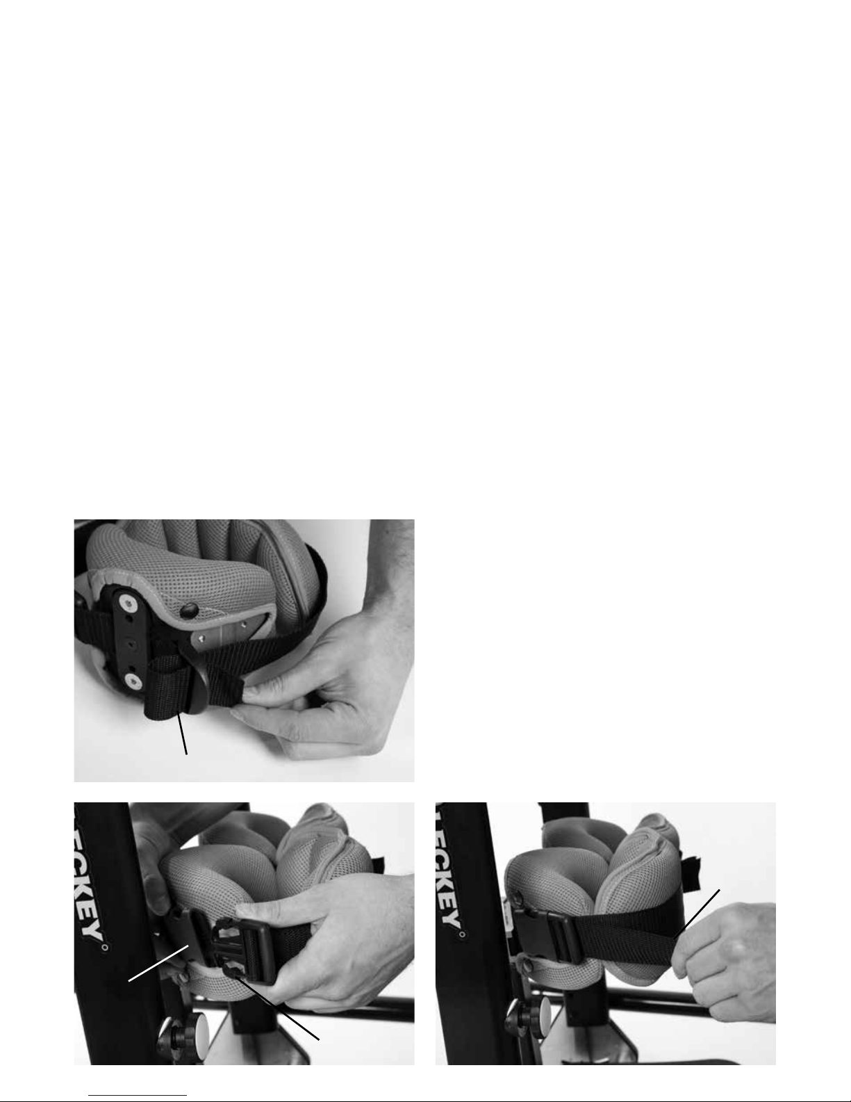
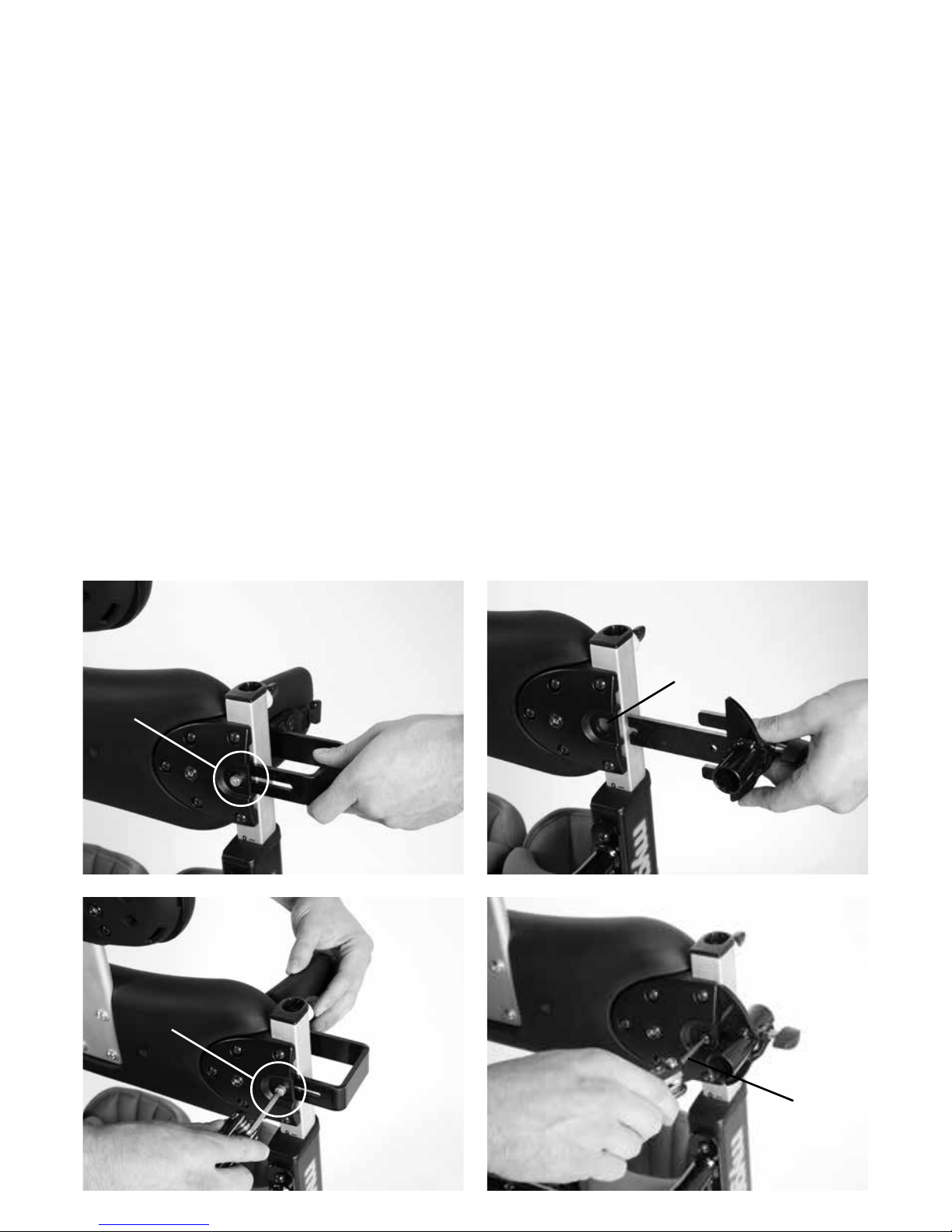
7.8 Attaching the Knee
Straps
First of all you will need to feed the webbing
through the plastic D ring as shown in (a).
To attach the knee straps insert the plastic
clip (b) into the buckle (c) on the side of the
main knee support. Then grab the straps
ends (d) and pull firmly away from the user,
which will secure the strap around the user’s
leg. To remove the strap, simply squeeze the
tabs on the top and bottom of the plastic clip
(b) and the strap will pop off.
A
B
C
D
Page 15
7.10 Attaching the hip belt
bracket
Before you can attach the de-rotation hip
belt you will first of all need to attach the hip
belt bracket. To do this slide the bracket into
the receiving slots in the hip pad metalwork
(a) and secure using the Allen bolt and
washer provided (b). Repeat this on the
other side. The de-rotation hip belt does not
require hip laterals.
7.9 Attaching Sandal
Raisers
If sandal raisers have been ordered,
attach them by placing them onto their
corresponding building block style recesses
on the footplate (a & b). Put the sandal on
top and secure with the sandal bolt (as per
section 7.4).
A
B
A
B
Page 16

7.11 Attaching the hip
laterals
The hip wrap around harness requires hip
laterals. To attach the hip laterals slide the
bracket into the receiving slot in the hip
pad metalwork (a) to the required width
and secure with the washer and Allen bolt
provided (b). Repeat this on the other side.
A
B
A
B
7.12 Attaching the
Posterior Support and
Pommel Receivers
If a posterior support is required, first attach
the posterior support receiver by sliding the
bracket into the receiving slots in the hip pad
metalwork (a) and secure with the washer
and allen bolts provided (b). Repeat this on
the other side.
Page 17
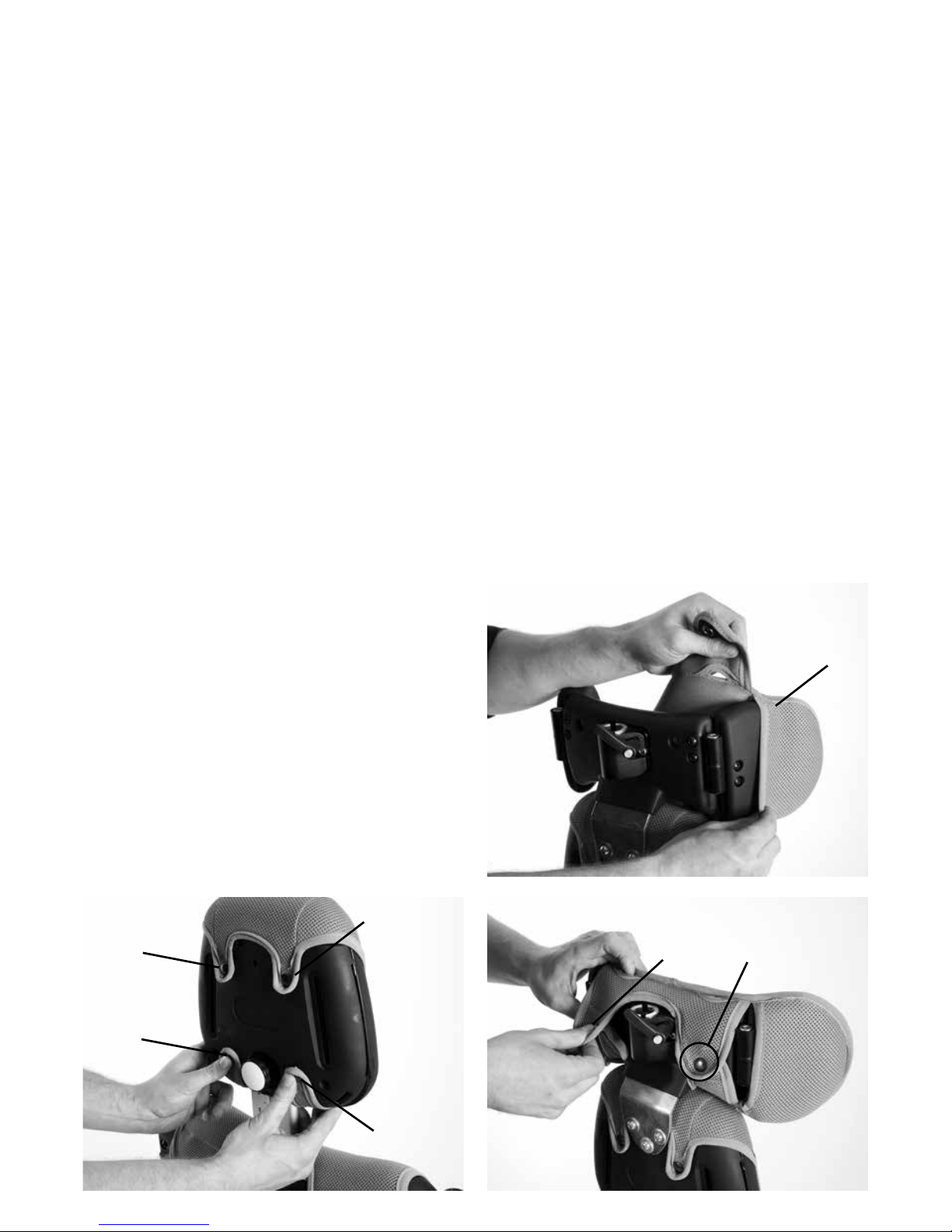
7.13 Attaching the
standard, flipaway &
complex chest laterals
The chest wrap around harness requires
chest laterals, either standard or flipaway.
Pull back the PU chest pad to gain access
(a). Then insert the lateral bracket together
with the angle adjustment mouldings into the
chest pad as shown (b), ensuring to insert
the plastic bosses into the chest pad slot (c).
Then secure from the outside with the Allen
bolt and washer supplied (d). Repeat this on
the other side.
Attaching the Pommel Receiver
Attach the pommel receiver (c) to the
bracket (d) on the hip pad, using allen bolts
provided (e).
A
C
B
D
E
C
Page 18
C
B
D
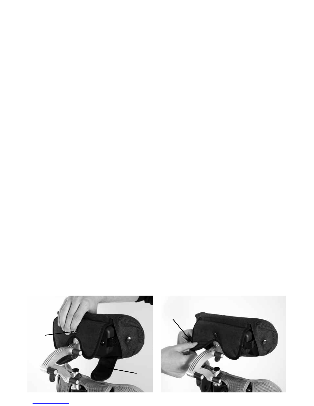
7.14 Attaching the chest/
hip wrap around harness
To attach the chest/hip wrap around harness,
slide the cushions onto the PU lateral with
the flaps towards the outside of the stander
(a), feed the plastic buckle (b) through the
hole in the cover, then bring the two Velcro
fastener straps (c) around the PU lateral and
attach them to the Velcro panel as shown.
Close over the flap (d). Repeat this on the
other side.
D
B
A
C
Page 19
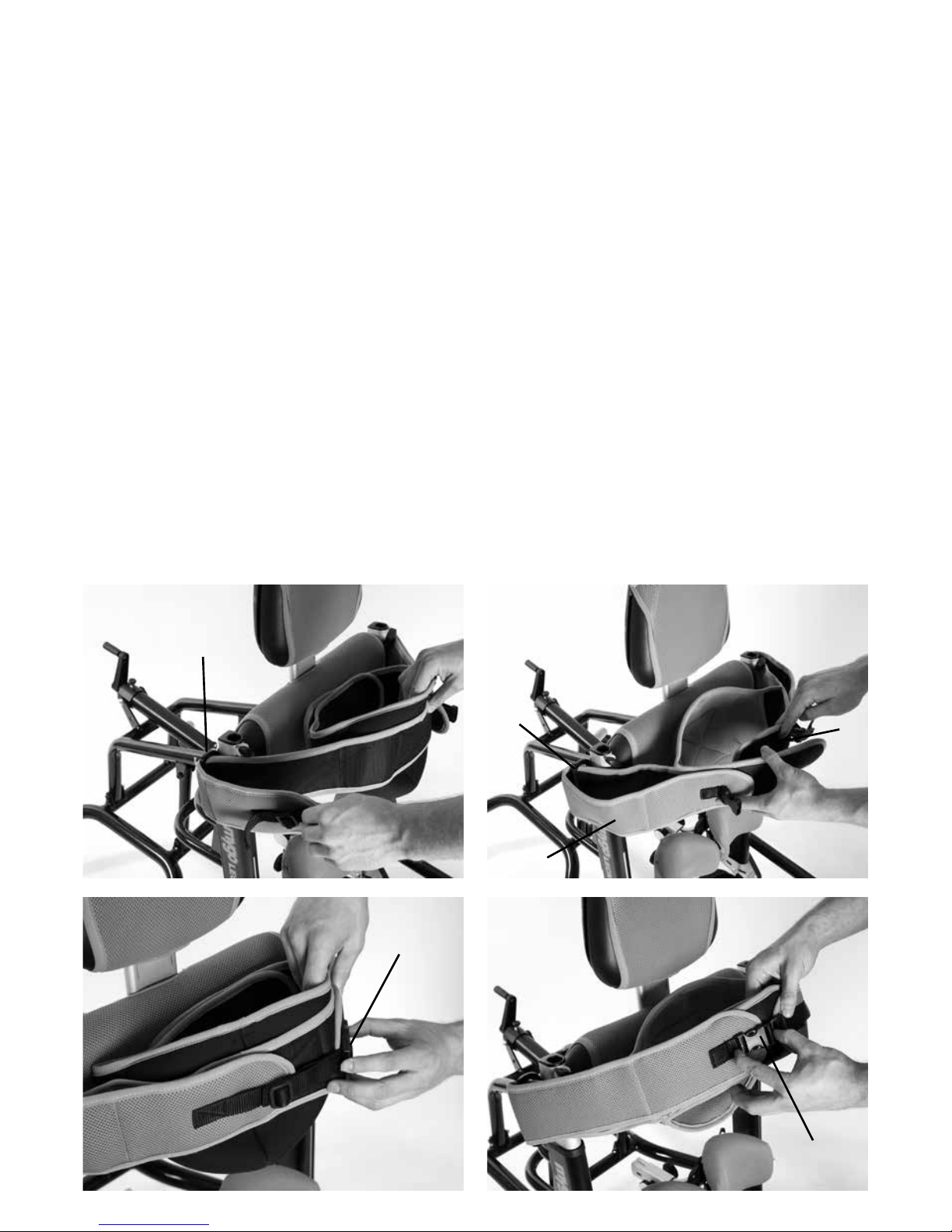
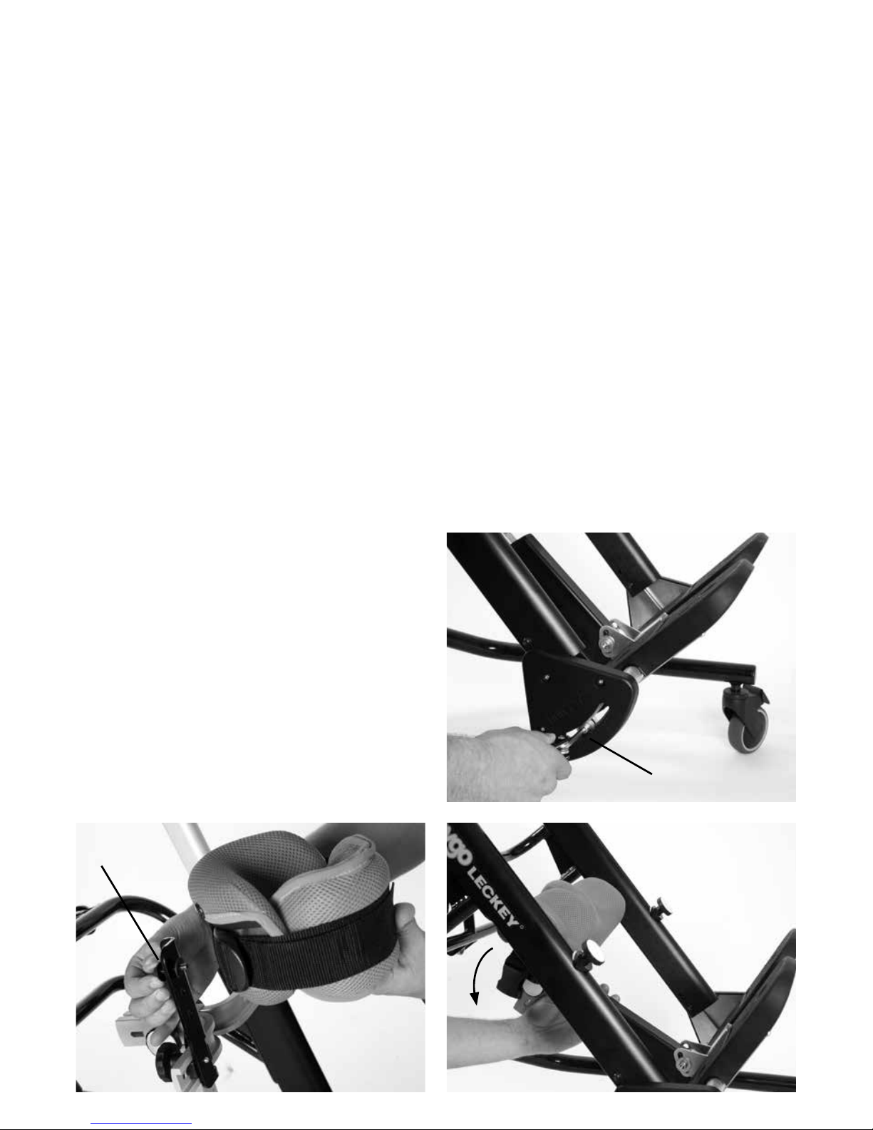
7.15 Attaching the Pelvic
band
There is a different pelvic band for prone
and supine standing. In prone the pelvic
band should be attached to the user first, if
possible on a mat. The inner pelvic band is
wrapped around the user’s pelvis and then
when the user is secured into the frame (by
their feet and chest) the longer straps are
slipped through the belt bars on the hip pad
(a) and secured firmly around the user. The
safety strap with the plastic buckle and clip
should then be secured to ensure the band is
not accidentally unfastened (b).
In supine the pelvic band should stay
attached to the product. When the user is
secured into the frame (by their feet and
chest) the inner pelvic band is wrapped
around the user’s pelvis (c) and then the
longer straps (d) are slipped through the belt
bars on the hip pad (if they are not already
through) (e) and secured firmly around the
user. The safety strap with the plastic buckle
and clip should then be secured to ensure
the band is not accidentally unfastened (f).
F
D
B
E
A
Page 20

Fitting
the Covers
8
Page 21
8.1 Knee Support Covers
Wrap the covers around the knee supports
and secure by pressing down on the four
snap fasteners. There are two on either side
of the knee support (a). Repeat this on the
other knee support.
8.2 Hip Pad Cover
Place the cover on the hip pad in the correct
orientation. Wrap the bottom flap underneath
the hip pad and press down on the snap
fasteners to secure (a) then wrap the top
flaps of the cover over the top of the hip pad
(b).
A
A
A
A
B
Page 22
8.3 Chest Pad Cover
Wrap the cover over the top of the chest pad
and secure by pressing down on the snap
fasteners (a). Then wrap the bottom section
underneath and press down on these snap
fasteners to secure (b).
8.4 Shoulder Support Pad
Follow the instructions in section 9.9 to angle
the shoulder support laterals inwards, slide
the cover over the shoulder wings (a) and
secure with the snap fasteners (b).
A
B
B
A
B
B
A
Page 23
8.5 Head cushion and cover
Place the cushion onto the head support.
Secure the central fastener (a). Bring the
lower flap under the head support (b) and
secure with the two remaining side fasteners
(c).
A
B
C
Page 24

Clinical Setup
for Postural
Management
9
The clinical setup of the
product should be completed
by a technically and clinically
competent person who has been
trained in the use of the product.
Leckey recommend a written
record is maintained of all clinical
setups for this product.
Page 25
9.1 Adjusting the Hip
Height
9.2 Adjusting the Chest &
Shoulder Support Height
To adjust the hip height, loosen the knobs on
either side of the stander (a), move the hip
pad to the required height and retighten the
knobs securely.
To adjust the chest height and the shoulder
support relative to the hip pad, loosen
the knob located at the back of the chest
support (a), adjust to the required height and
retighten securely.
A
A
A
Page 26
9.3.1 Adjusting the knee
supports
The height, depth and lateral position
of the knee supports can be positioned
independently. To alter the height of the
knee supports, loosen the knob located at
the back of the knee post (a), adjust until
the required height has been achieved and
retighten. To alter the individual depth of the
knees, loosen the knob at the side of the
knee post (b), adjust to the required depth
and retighten securely. To alter the lateral
position of the knees, loosen the knob at
the back of the knee pad (c), adjust to the
required position and retighten securely.
A
B
C
Page 27

9.3.2 Attaching the
extended knee brackets
Loosen Knob (c) and remove knee support.
Slide extension bracket unto the knee
bracket and secure with white rubber
washer, silver washer, plastic spacer and
knob.
Fix the knee supports to the extension
brackets at the required height using black
rubber washer, black washer and M6 screw.
C
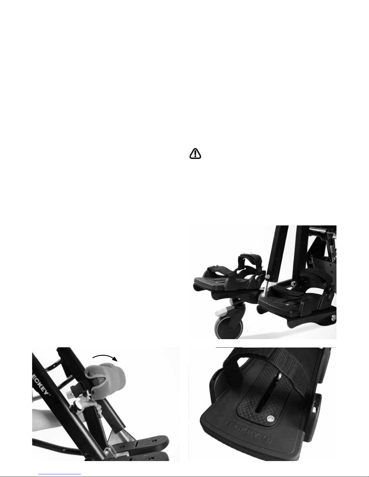
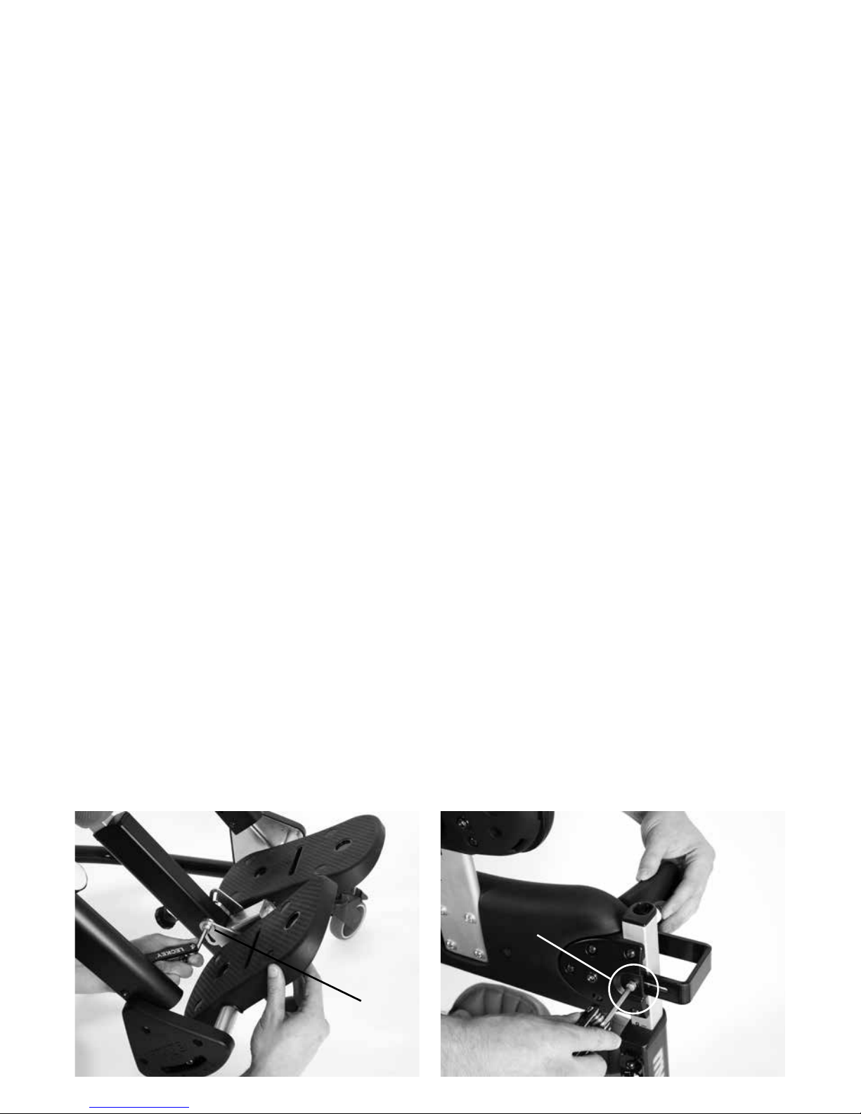
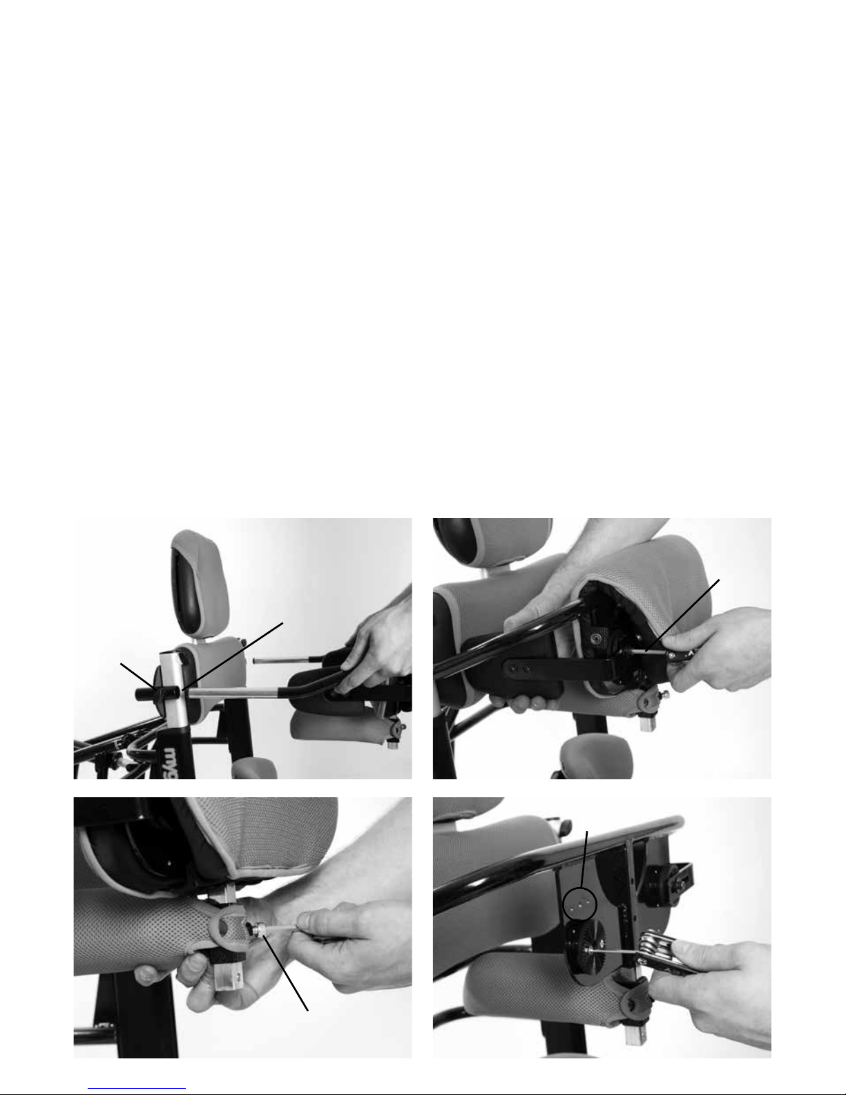
9.4 Adjustment to
accommodate the
contracture angle
If possible, adjustment of the swinging
footplate on the Mygo stander should
be performed when the client is out
of the stander. However there may be
circumstances where it is necessary or
preferable to adjust the angle of the swinging
footplate with the client in the stander. This
process requires two competent persons;
one to make the adjustments and one to
assess the comfort of the client during the
adjustment, and is best performed with the
stander in a horizontal position.
In upright or prone standing:
Assess the client’s range of movement,
muscle tone, etc, on a plinth and determine
the optimum standing posture before
positioning the client in the stander. Position
the client in the Mygo stander. While carefully
Prone
Configuration
A
B
Page 28
Supine
Configuration
supporting the head and shoulders, move
the client into a horizontal position. Open the
knee straps and sandal straps. Loosen the
Allen (a) bolt on both sides of the swinging
footplate ensuring the weight of the user’s
knees are supported by a carer, adjust the
angle of the swinging footplate as necessary,
always taking care to assess the client’s
comfort, and retighten the bolts securely.
Then secure the knee straps and sandal
straps. Return the client to prone standing
position.
In supine standing:
Assess the client’s range of movement,
muscles tone, etc, on a plinth and determine
the optimum standing posture before
positioning the client in the stander. Position
the client in the Mygo stander and move it
into a horizontal position. Open the knee
straps and sandal straps. Loosen the
Allen bolt (a) on both sides of the swinging
footplate ensuring the weight of the user’s
knees are supported by a carer, adjust the
angle of the swinging footplate as necessary,
always taking care to assess the client’s
comfort, and retighten the bolts securely.
Then secure the knee straps and sandal
straps. Return the stander to preferred
supine standing angle.
B
A
9.5 Positioning the sandals
Each sandal is attached to the individual
footplate with a single fixing bolt. The
footplate is encapsulated in rubber to ensure
the sandals do not slide when secured.
To position the user’s feet in the sandals
secure the Velcro straps provided so the foot
is held in place. The straps should be over
the bridge of the foot and over the toes. The
front strap can be fed through one of two
slots on either side of the sandals, depending
on the size of the user’s feet (2).
If the child is wearing sandals or light
footwear check the straps to make sure
the webbing does not irritate the skin.
1
2
Page 29
9.7 Adjusting the Hip
Laterals
To set the width of the hip laterals, loosen
the Allen bolts at the back of the hip pad (a),
adjust to desired width and retighten.
9.6 Secondary Footplate
Angle
To set the angle to accommodate plantarflexion or dorsi-flexion, simply loosen the
Allen bolt located by the knee post to the
inside of the footplate (a), place in the
required position and then retighten the bolt
securely. 10° of flexion is accommodated in
each direction.
A
A
Page 30

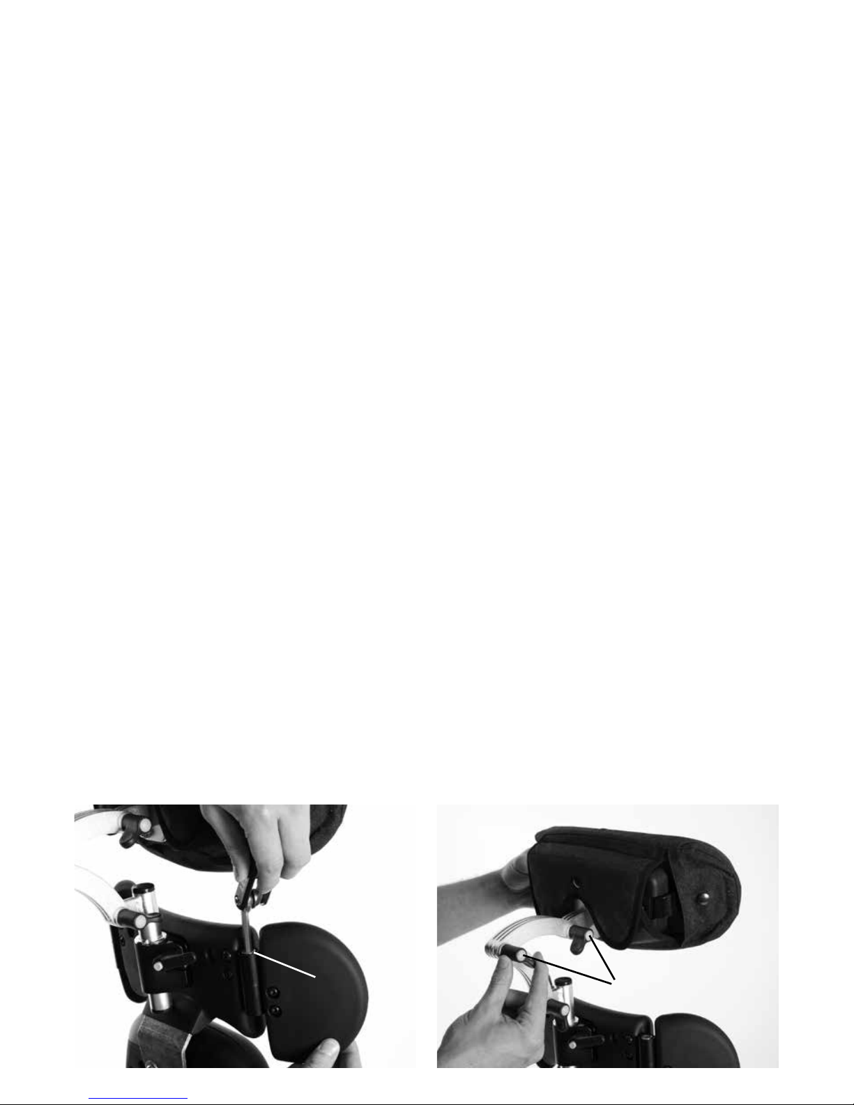
9.8 Adjusting the standard,
complex and flipaway chest
lateral supports
To adjust the height and angle of the lateral
supports, loosen the Allen bolt (a), adjust
to the required width, height and angle and
retighten securely.
A
Complex laterals
The complex laterals can also be angled to
allow the pad to contour to the user’s shape.
To adjust loosen the screw (b) at the centre
of the pad, angle the pad to the required
position and retighten the screw. The laterals
can be flipped away to aid transfer, by
pulling the pin (c) at the back and rotating
the support out of the way.
B
C
Page 31
9.9 Shoulder Support 9.10 Headrest
To adjust the angle of the shoulder support
laterals, loosen the Allen bolt screw (a), move
laterals to required angle and retighten.
To adjust the height, depth and angle of the
headrest, loosen the hand knobs (a) and
when set to the desired position retighten the
knobs. Do not remove the headrest while the
user is in the stander.
A
A
Page 32

9.11 Attaching and
adjusting the posterior
support and pommel
To adjust the posterior support, loosen
receiver allen bolt (a) slide the outside bars
into the receivers (b) to the required depth
and tighten (a).
C
A
B
D
E
Page 33

9.12 Increase Tray
Adjustment
To increase the depth adjustment of the
tray, reposition the tray bars further back.
To do this, unscrew the Allen bolts holding
the tray bars on (a), move the bars to the
holes further back (b) replace the bolts and
retighten all bolts securely.
A
B
Attaching and adjusting the pommel
To attach the pommel, loosen the receiver
allen bolt (c), slide the pommel into the
receiver (d) and tighten at the required depth.
The height can also be adjusted using the
allen bolt (e) at the back of the pommel.
C
D
E
Page 34

9.13 Attaching and
Adjusting the Tray
Grab Rails
To attach the grab rails firstly remove tray
bars. To do this, unscrew the Allen bolts
holding the tray bars on (a) (note positioning
holes used). Place down spacer plate (b),
then slotted plate (c). Secure, with tray bar in
original holes, using supplied longer screws
(d). Repeat this on the other side.
A
B
C
Page 35

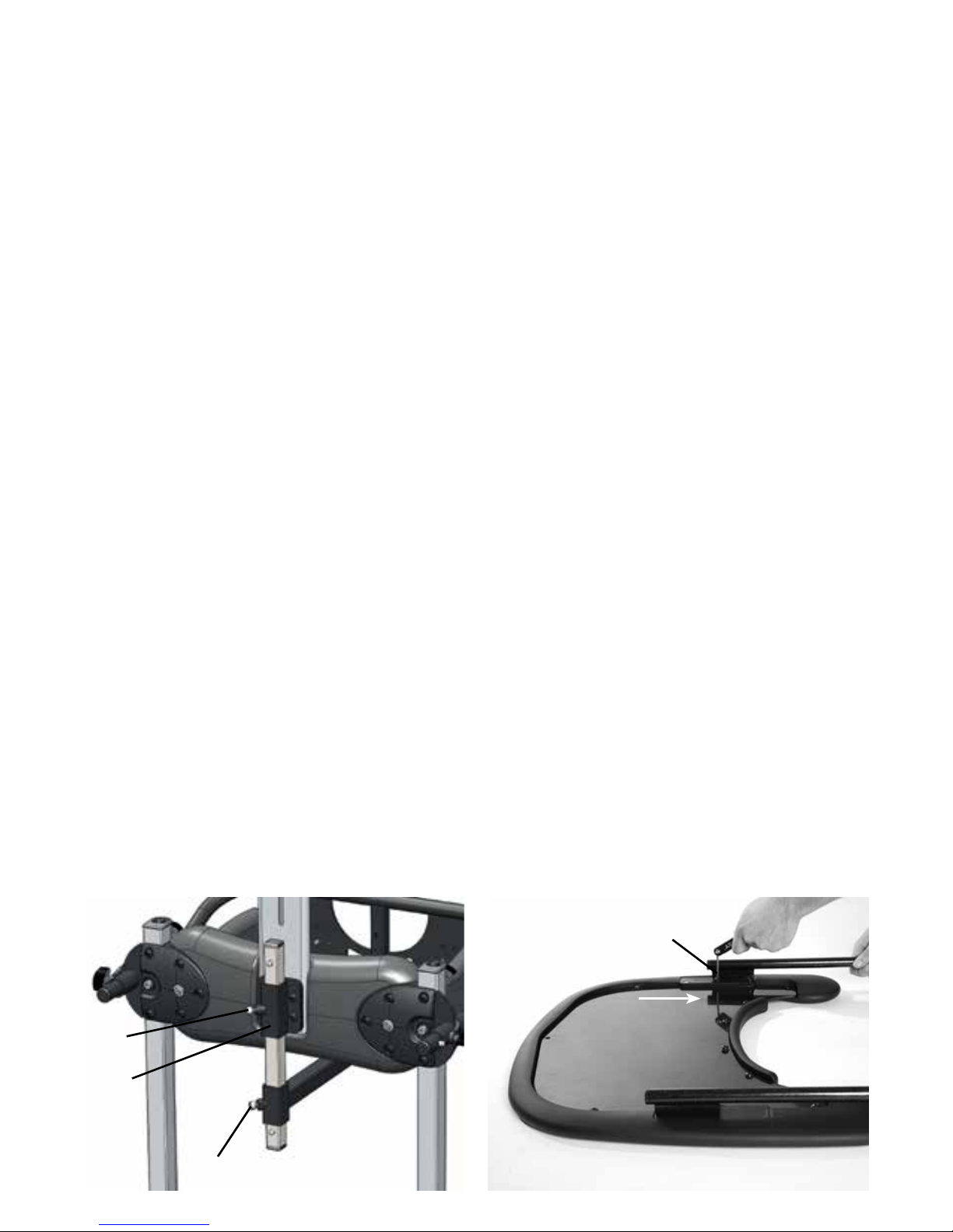
9.14 Tray Insert Changes
To swap out different inserts for tray, firstly,
turn the tray upside down, then remove Allen
bolts holding in the current insert (a) and
tray protection pad (if there is one). Remove
old insert (b) and replace with new one and
secure to tray and add tray protection pad
using same Allen bolts.
A
B
F
Attach the grab rail receiving brackets (e) as
shown. Place the grab rail into the receiving
brackets. Adjust to the required height and
tighten (f) on both sides.
E
Page 36

Frequent
Adjustments
for Daily Use
10
Parents and carers should be
shown how to make frequent
adjustments and made aware
of the safety checks in section
6 by a technically and clinically
competent person who has been
trained in the use of the product.
Leckey recommend that a written
record is maintained of all parent
and carers who have been trained
in the use of this product.
Page 37
10.1 Transferring the user
into and out of the Stander
10.2 Setting the
Stander Angle
Before transferring the child into the stander
carry out the daily product inspection as
outlined in section 12 of this user manual.
We would recommend that users are never
transferred straight from seating to standing
without preparation and stretching. This
is best done in a lying position whilst on a
mat but can be carried out in a wheelchair
or seating system if required. Before
transferring the child into the product lock
all the castors, ensuring that they are facing
outwards to maximise product stability. Make
sure the straps on the chest harness, pelvic
band, knee straps and sandals are released
and out of the way to facilitate transfer.
Whether used in supine or prone the frame
angle can be easily adjusted by pulling and
twisting the safety lock (a) and turning the
handle (b) until the desired angle has been
achieved (the angle can be read from the
cross bar (c). Turn the handle clockwise to
bring it upright and anti-clockwise to bring it
towards horizontal. The stander can adjust
from vertical (0°) through to 10° off horizontal
(80°). This can be done whilst the child in
the product.
Ensure that the product and user are
away from surrounding furnishings to
prevent possible collisions when adjusting
the angle.
C
A
B
Page 38

10.4 Knee Straps
To attach the knee straps insert the plastic
clip (a) into the buckle (b) on the side of the
main knee support. Then grab the straps
ends (c) and pull firmly away from the user,
which will secure the strap around the user’s
leg. To remove the strap, simply squeeze the
tabs on the top and bottom of the plastic clip
and the strap will pop off.
Always check with your therapist as to the
correct tensioning of the straps for your
child as the kneecap is a sensitive area
and too much force could cause injury.
A
B
C
10.3 Positioning the
Sandals
To position the user’s feet in the sandals,
secure the Velcro straps provided so the foot
is held in place. The straps should be placed
over the bridge of the foot over the toes.
The front strap can be fed through one
of two slots on either side of the sandals,
depending on the size of the user’s feet (2).
If the child is wearing sandals or light
footwear check the straps to make sure
the webbing does not irritate the skin.
1
2
Page 39

10.5 Positioning and
attaching the Pelvic band
There is a different pelvic band for prone
and supine standing. In prone the pelvic
band should be attached to the user first, if
possible on a mat. The inner pelvic band is
wrapped around the user’s pelvis and then
when the user is secured into the frame (by
their feet and chest) the longer straps are
slipped through the belt bars on the hip pad
(a) and secured firmly around the user. The
safety strap with the plastic buckle and clip
should then be secured to ensure the band is
not accidentally unfastened (b).
In supine the pelvic band should stay
attached to the product. When the user is
secured into the frame (by their feet and
chest) the inner pelvic band is wrapped
around the user’s pelvis (c) and then the
longer straps (d) are slipped through the belt
bars on the hip pad (if they are not already
through) (e) and secured firmly around the
user. The safety strap with the plastic buckle
and clip should then be secured to ensure
the band is not accidentally unfastened (f).
C
F
D
B
E
A
Page 40

10.6 Wrap Around
Lateral Harness
To open the wrap around chest harness,
simply unclip the side buckle (a) and open.
Reverse the process when placing the user
back in the product, ensuring to secure the
straps firmly around the user. The safety
strap with the plastic buckle and clip should
then be secured to ensure the band is not
accidentally unfastened (a).
Always secure the chest and hip support
harnesses (and knees straps when used
in supine) first before making other
adjustments.
Always make sure the plastic buckles are
fully engaged.
A
Page 41

10.7 Tray Adjustment
To insert and adjust the depth of the tray,
loosen the knobs on the back of both tray
receivers (a), slide the tray in to the required
depth, and retighten. To increase the depth
adjustment further, see 9.12.
To adjust the angle of the tray, loosen the
plastic handle in the centre of both the tray
receivers (b), set the tray to the required
angle and tighten the plastic handles again
securely.
To adjust the tray height, loosen the knobs
at the top of the hip pad (c) adjust receivers
to required height and retighten, ensuring the
tray is at a level height by matching the scale
on the side of the tray receiver bars.
Never use the tray to steer or push the
chair.
Do not place hot objects (hotter than 40°
Celsius) on the tray.
Please note that the tray is for the use of
the user only.
Do not lean or place heavy objects
(heavier than 8kgs/17.6lbs) on the tray.
C
A
B
Page 42

11 Cleaning & Care
Information
How to Maintain
When cleaning the product we recommend
that you use only warm water and a
nonabrasive detergent. Never use organic
solvents or dry cleaning fluids.
Upholstery and fabrics
1. The upholstery and fabrics can be
removed and machine washed and tumble
dried at a low setting. The standard covers
can be washed at 40 degrees Celsius and
the Infection Control covers at 90 degrees
Celsius. Please remove the foam before
washing the head support, posterior support
and pommel covers. All other soft upholstery
can be placed directly in the washing
machine.
2. If the upholstery is to be cleaned in-situ,
the best cleaning method is a ‘wipe & dry’
technique.
3. Staining should be removed as quickly
as possible with absorbent cloth, towels or
a sponge. Routine soap and warm water
sponging is effective for ordinary soiling
and minor spills. Be careful not to over wet
the fabric, as this will cause the staining to
spread.
4 Antiseptic cleaning agents can be used
on more stubborn stains. These may require
a safe solvent such as Isopropyl Alcohol or
Mineral Spirit. A half cup of household bleach
to 5 litres of water can also be used as a
useful disinfectant.
5 Always ensure the product is dry before
use.
Metal and plastic components
1. Soap and water or antibacterial spray can
be used for daily cleaning.
2. For deep cleaning a low pressure steam
cleaner can be used.
3. Do not use solvents to clean plastic or
metal components.
4. Make sure the product is dry before use.
Page 43

12 Daily Product Inspection
(Therapists, Parents & Carers)
We recommend that daily visual checks of
the equipment are carried out by therapists,
carers or parents to ensure the product is
safe for use. The recommend daily checks
are detailed below.
1. Ensure all adjustment knobs and bolts are
in place and secure.
2. Check all upholstery for signs of wear and
tear.
3. Check all wheels are moving freely and
lock securely.
4. Check all Velcro strips and brush fluff to
ensure straps secure firmly.
If in any doubt to the continued safe
use of your Leckey product or if any
parts should fail, please cease using
the product and contact our customer
services department or your local dealer
as soon as possible.
Page 44

13 Annual Product
Inspection
(Therapist, Technician, Leckey Product
Advisor, Dealer)
Leckey recommend that each product should
be subject to a detailed inspection at least
once a year and every time the product is
reissued for use. This inspection should
be carried out by a technically competent
person who has been trained in the use of
the product and should include the following
checks as a minimum requirement.
1. Check all knobs, nuts, bolts and plastic
buckles are in place, replacing any missing
items. Paying particular attention to the
following items;
> Buckles and Velcro on pelvic bands, knee
straps and wrap around lateral harnesses
> Hip, knee and chest height adjust and lock
securely
> Contracture angle and secondary footplate
angle adjust and lock securely
> Knee supports depth and width adjust and
lock securely
> Head support locks securely
2. Lift the base to check each wheel
individually. Make sure they are moving freely
and remove any dirt from the rubber wheels.
Check that the brakes lock the wheels
securely.
3. Visually check the structure of the product
ensuring there are no signs of fatigue or
cracking around the welds.
4. Visually check the plastic parts of the
product ensuring there are no signs of
fatigue or cracking.
5. Leckey recommend that a written record is
maintained of all annual product inspections.
If in any doubt to the continued safe
use of your Leckey product or if any
parts should fail, please cease using
the product and contact our customer
services department or your local dealer
as soon as possible.
Page 45

14 Re-issuing Leckey
Products
Most Leckey products are assessed and
ordered to meet the needs of an individual
user. Before reissuing a product we
recommend that the therapist prescribing
the product has carried out an equipment
compatibility check for the new user and has
ensured that the product being re-issued
contains no modifications or special
attachments.
A detailed technical inspection should be
carried on the product prior to re-issuing.
This should be carried out by a technically
competent person who has been trained in
the use and inspection of the product. Please
refer to section 13 for the required checks to
be carried out.
Ensure the product has been cleaned
thoroughly in accordance with section 11 of
this manual.
Ensure a copy of the user manual is supplied
with the product. A copy can be downloaded
from our website www.leckey.com.
Leckey recommend that a written record is
maintained of all product inspections carried
out during the reissue of the product.
If in any doubt to the continued safe use of
your Leckey product or if any parts should
fail, please cease using the product and
contact our customer service department or
your local dealer as soon as possible.
15 Product Servicing
Servicing of all Leckey products should only
be carried out by technically competent
persons who have been trained in the use of
the product.
In the UK & ROI please contact the Leckey
Service Centre on UK 0800 318265 or ROI
1800 626020 and our customer service
department will be delighted to assist you
with your servicing requirements.
All international service enquiries should be
directed to the appropriate Leckey distributor
who will be delighted to assist you. For
further information on Leckey distributors
please visit our website www.leckey.com.
Page 46

16 Technical Data
Size
Age (Years Approx)
Max user weight
Max knee contracture accommodated
Product weight
Tray height range (from top of hip pad)
User height
min
max
Chest support height (footplate to armpit)
min
max
Chest width (distance between laterals)
min
max
Hip support height (footplate to mid
buttocks)
min
max
Hip width (distance between hip guides)
min
max
Footplate angle
Plantarflexion
Dorsiflexion
Product angle range
Prone
Supine
Stander footprint
Length
Width
Tray angle adjustment
Prone
Supine
1
4 - 10
mmmminches
inches
2
8 - 14
42.5
57.1
29.9
42.5
6.3
11.0
18.1
28.7
8.7
13.0
0 - 6
48lbs
38.5
24.8
55lbs
44.5
25.6
110lbs 132lbs
1350
1750
980
1300
200
320
620
875
280
390
10°
10°
45°
45°
25°
0 - 150
53.1
66.9
38.6
51.2
7.9
12.6
24.4
34.4
11.0
15.4
0 - 6
1080
1450
760
1080
160
280
460
730
220
330
10°
10°
0° to 80°
0° to 80°
0° to 80°
0° to 80°
45°
45°
25°
0 - 150
22kgs
978
630
25kgs
1130
650
50kgs 60kgs
Page 47

Product and accessory
codes
Code Mygo Stander
143-1600 Size 1 stander - with manual angle adjustment, PU chest pad, PU hip
pad, PU knee supports, two piece footplate
143-2600 Size 2 stander - with manual angle adjustment, PU chest pad, PU hip
pad, PU knee supports, two piece footplate
143-1770-09 Size 1 Cover pack - pink (contains chest pad, hip pad and knee
pad covers)
143-1770-08 Size 1 Cover pack - blue (contains chest pad, hip pad and knee
pad covers)
143-1770-07 Size 1 Cover pack - orange (contains chest pad, hip pad and knee
pad covers)
143-2770-09 Size 2 Cover pack - pink (contains chest pad, hip pad and knee
pad covers)
143-2770-08 Size 2 Cover pack - blue (contains chest pad, hip pad and knee
pad covers)
143-2770-07 Size 2 Cover pack - orange (contains chest pad, hip pad and knee
pad covers)
143-1638 Shoulder pad
143-1768-09 Shoulder pad cover - pink
143-1768-08 Shoulder pad cover - blue
143-1768-07 Shoulder pad cover - orange
120-859 Headrest hardware
143-1787 Headrest cushion and cover - infection control (black)
137-800-05 Headrest cushion and cover (black)
137-699-05 Headrest cushion and cover (black) (includes hardware)
143-1662 Headrest - infection control (black) (include hardware)
143-1619 Chest lateral hardware only (pair)
143-1675 Flipaway laterals hardware (pair)
143-1673 Complex lateral vertical - right hand side (single with cover)
143-1674 Complex lateral vertical - left hand side (single with cover)
143-1780-09 Size 1 chest/hip wraparound harness - pink
143-1780-08 Size 1 chest/hip wraparound harness - blue
143-1780-07 Size 1 chest/hip wraparound harness - orange
143-1775-14 Size 1 chest/hip wraparound harness - infection control (black)
143-2780-09 Size 2 chest/hip wraparound harness - pink
143-2780-08 Size 2 chest/hip wraparound harness - blue
143-2780-07 Size 2 chest/hip wraparound harness - orange
143-2775-14 Size 2 chest/hip wraparound harness - infection control (black)
143-3780-09 Size 3 chest/hip wraparound harness - pink
143-3780-08 Size 3 chest/hip wraparound harness - blue
143-3780-07 Size 3 chest/hip wraparound harness - orange
143-3775-14 Size 3 chest/hip wraparound harness - infection control (black)
143-1798-09 Size 1 prone derotation hip belt - pink (includes hardware)
143-1798-08 Size 1 prone derotation hip belt - blue (includes hardware)
Page 48

143-1798-07 Size 1 prone derotation hip belt - orange (includes hardware)
143-2798-09 Size 2 prone derotation hip belt - pink (includes hardware)
143-2798-08 Size 2 prone derotation hip belt - blue (includes hardware)
143-2798-07 Size 2 prone derotation hip belt - orange (includes hardware)
143-1783-09 Size 1 supine derotation hip belt - pink (includes hardware)
143-1783-08 Size 1 supine derotation hip belt - blue (includes hardware)
143-2783-07 Size 1 supine derotation hip belt - orange (includes hardware)
143-2783-09 Size 2 supine derotation hip belt - pink (includes hardware)
143-2783-08 Size 2 supine derotation hip belt - blue (includes hardware)
143-2783-07 Size 2 supine derotation hip belt - orange (includes hardware)
143-1663 Hip lateral hardware only (pair)
143-1776-09 Size 1 basic knee straps - pink
143-1776-08 Size 1 basic knee straps - blue
143-1776-07 Size 1 basic knee straps - orange
143-1776-14 Size 1 basic knee straps - infection control (black)
143-2776-09 Size 2 basic knee straps - pink
143-2776-08 Size 2 basic knee straps - blue
143-2776-07 Size 2 basic knee straps - orange
143-2776-14 Size 2 basic knee straps - infection control (black)
143-1778-09 Split knee straps - pink - fits both sizes
143-1778-08 Split knee straps - blue - fits both sizes
143-1778-07 Split knee straps - orange - fits both sizes
143-1690 Extended knee brackets
143-1609 Size 1 Mygo stander tray
143-1633 Size 1 Mygo stander tray with bowl insert
143-1610 Size 1 Mygo stander tray with clear insert
143-2609 Size 2 Mygo stander tray
143-2633 Size 2 Mygo stander tray with bowl insert
143-2610 Size 2 Mygo stander tray with clear insert
143-1624 Size 1 posterior support and pommel (fits size 1 stander only)
143-2624 Size 2 posterior support and pommel (fits size 2 stander only)
143-1790-09 Posterior support cover - pink
143-1790-08 Posterior support cover - blue
143-1790-07 Posterior support cover - orange
143-1790-14 Posterior support cover - infection control
143-1792-09 Pommel support cover - pink
143-1792-08 Pommel support cover - blue
143-1792-07 Pommel support cover - orange
143-1792-14 Pommel support cover - infection control
152-1600 Sandals Size 1
152-2600 Sandals Size 2
152-3600 Sandals Size 3
143-1615 Sandal raisers
143-1649 Grab rail
Page 49

Page 50

Indice
01 Destinazione d’uso
02 Dichiarazione di Conformità
03 Termini di Garanzia
04 Documentazione sulla storia del prodotto
05 Formazione sull’uso del prodotto
06 Informazioni sulla sicurezza
07 Come rimuovere dall’imballo ed assemblare lo standing posturale
08 Inserire i rivestimenti
09 Configurazione clinica per la gestione della postura
10 Regolazioni frequenti per l’uso quotidiano
11 Informazioni sulla pulizia e sulla manutenzione
12 Controllo quotidiano del prodotto
13 Controllo annuale del prodotto
14 Ri-assegnare i prodotti Leckey
15 Assistenza prodotto
16 Informazioni tecniche
Lo standing posturale Mygo può essere sistemato
in posizione prona, verticale o supina per consentire
un programma terapeutico posturale variegato.
Può essere utilizzato da uno o più bambini. Lo
standing posturale Mygo favorisce e accresce
le funzionalità per bambini con diversi gradi di
disabilità e, grazie agli intelligenti supporti per le
ginocchia e ai poggiapiedi dinamici, consente di
sottoporre alla terapia posturale anche quei bambini
con contratture fisse del ginocchio fino a 25 gradi. Il
suo utilizzo è facile e intuitivo ed è più semplice fare
assumere al proprio bambino una posizione eretta,
comoda e sicura. Facilita la posizione eretta e, allo
stesso tempo, presenta una gamma più vasta di
funzionalità complesse. Il presente manuale spiega
come utilizzarne tutte le funzioni in modo semplice
e veloce. Le istruzioni sulla sicurezza e sulla
manutenzione garantiranno un uso del prodotto
protratto nel tempo.
Page 51

1. Destinazione d’uso
Lo standing posturale Mygo viene
utilizzato per la posizione prona, supina
e verticale. Lo standing posturale Mygo
è disponibile in due formati: il formato 1
è destinato ai bambini di età compresa
tra i 4 e i 10 anni, mentre il formato 2
è destinato a bambini e ragazzi di età
compresa tra gli 8 e i 14 anni. Il peso
massimo consentito è di 50 kg e 60 kg
rispettivamente.
2. Dichiarazione di Conformità
Il produttore, James Leckey Design
Ltd., dichiara, sotto la propria e unica
responsabilità, che lo standing posturale
Mygo è conforme ai requisiti della direttiva
93/42/CEE e della norma EN 12182 —
Ausili tecnici per persone disabili e metodi
di prova.
3. Termini di Garanzia
La garanzia si applica solo se il
prodotto viene utilizzato in conformità
con le condizioni specificate e la sua
destinazione d’uso, rispettando tutte le
raccomandazioni del produttore (si vedano
anche le condizioni generali di vendita,
consegna e pagamento). Tutti i prodotti
e i componenti Leckey sono garantiti due
anni.
4. Documentazione sulla storia
del prodotto
Il vostro prodotto Leckey è un dispositivo
medico di Classe 1 e, in quanto tale,
dovrebbe essere prescritto, configurato
o riassegnato da personale tecnico
competente, che è stato formato sull’uso
di questo prodotto.
Leckey consiglia di conservare una
documentazione scritta che fornisca
le informazioni relative a tutte le
impostazioni, i controlli relativi alla
riassegnazione del prodotto e i controlli
annuali.
5. Documentazione relativa alla
formazione sull’uso del prodotto
(genitori, insegnanti e assistenti)
Il vostro prodotto Leckey è un dispositivo
medico di Classe 1 e, in quanto tale,
Leckey raccomanda che genitori,
insegnanti e assistenti che fanno uso
di questa attrezzatura vengano messi a
conoscenza delle seguenti sezioni del
presente manuale da personale tecnico
competente.
Sezione 6
Informazioni sulla sicurezza
Sezione 9
Configurazione clinica per la gestione
della postura
Sezione 10
Regolazioni frequenti per l’uso quotidiano
Section 11
Informazioni sulla pulizia e sulla
manutenzione
Section 12
Controllo quotidiano del prodotto
Leckey consiglia di conservare la
documentazione scritta riguardante tutti
coloro che sono stati formati all’uso
corretto del prodotto.
Page 52

6.1 Prima dell’uso leggere sempre con
attenzione le istruzioni.
6.2 Mentre si usano le attrezzature
Leckey, non lasciare mai soli gli utenti.
6.3 Applicare al prodotto solamente
componenti approvati da Leckey. Non
apportare modifiche al prodotto in nessun
modo. La mancata osservanza delle
istruzioni potrebbe mettere in pericolo
l’utente o l’assistente e annullare la
garanzia sul prodotto.
6.4 Qualora ci fossero dubbi sulla
persistenza dell’uso in sicurezza del
prodotto o nel caso in cui alcune sue
parti dovessero rompersi, si prega
di interrompere l’uso del prodotto e
contattare il nostro customer service o il
rivenditore locale il prima possibile.
6.5 Regolare il prodotto in tutte le
posizioni e assicurarsi che siano tutte
ben salde prima di far sedere l’utente.
Per alcune regolazioni potrebbe essere
necessario utilizzare uno strumento che
viene fornito con ogni prodotto. Tenere
tutti gli strumenti fuori dalla portata dei
bambini.
6.6 Quando si fa posizionare l’utente
sul telaio per la posizione eretta, per
ragioni di sicurezza fissare sempre prima
i suoi piedi e le cinghie per lo sterno.
Quindi fissare le cinghie per le cosce e le
ginocchia.
6.7 Quando lo standing posturale viene
utilizzato nella posizione supina, è
importante assicurarsi che le pelotte per
le ginocchia siano ben salde. Controllare
sempre che i bottoni automatici siano
chiusi correttamente.
6.8 Anche se lo standing posturale
presenta delle ruote, non è un dispositivo
per la mobilità. Assicurarsi sempre che i
freni delle ruote siano bloccati per tutto il
tempo in cui viene utilizzato il telaio, che
vengano regolati o anche solo conservati.
6.9 Quando si regola l’inclinazione
dello standing posturale Mygo Leckey,
assicurarsi che l’utente e tutte le parti
del prodotto siano distanti dai mobili
circostanti per evitare possibili collisioni.
6.10 È possibile regolare la posizione
accuratamente e in sicurezza anche
quando l’utente è posizionato nel
prodotto. Ma è importante sostenere
tutte le pelotte quando vengono regolate
mentre l’utente è posizionato nel prodotto.
6.11 Non lasciare mai il prodotto su
superfici con pendenze maggiori di 5
gradi. Ricordarsi sempre di bloccare tutte
le rotelle.
6.12 Il prodotto contiene componenti
che potrebbero costituire un rischio
di soffocamento per bambini piccoli.
Controllare sempre che le manopole e
i bulloni di bloccaggio raggiungibili dal
bambino siano sempre ben serrati e saldi.
6.13 I prodotti Leckey sono conformi
al regolamento sulla sicurezza contro
l’incendio ai sensi della norma EN 12182.
Tuttavia, il prodotto contiene componenti
in plastica e, quindi, dovrebbe essere
tenuto lontano da tutte le fonti dirette
di calore come fiamme libere, sigarette,
riscaldatori elettrici e a gas.
6 Informazioni sulla
sicurezza
Page 53

6.14 Non posizionare mai oggetti caldi
sul vassoio di lavoro perché potrebbero
danneggiare la plastica.
6.15 Pulire regolarmente il prodotto. Non
utilizzare detergenti abrasivi. Effettuare
controlli di manutenzione regolari per
assicurarsi che il prodotto funzioni
correttamente
6.16 The product is designed for indoor
use and when not in use should be
stored in a dry place that is not subjected
to extremes of temperature. The safe
operating temperature range of the
product is +5° to +40° Celsius.
Page 54

Come
rimuovere
dall’imballo ed
assemblare lo
standing
posturale
7
Il vostro standing posturale
Mygo vi verrà consegnato
smontato in una scatola di
cartone. Innanzitutto, tirare fuori
tutto il contenuto della scatola e
controllare tutte le parti ordinate.
Page 55

Per assemblare il prodotto con lo standing
posturale in posizione verticale, sollevarlo
dalla traversa (a), posizionare i tubi verticali
fra le alette libere della base e allineare i fori
(b) (la scanalatura nel tubo verticale dovrebbe
aiutare il posizionamento).
Aggiungere i bulloni e serrare (c). Ripetere
dall’altra parte. Quindi sollevare l’attuatore
manuale sulle alette libere nella traversa ed
allineare i fori, quindi aggiungere i bulloni e
serrare (d).
A
C
A
B
D
B
D
Page 56

7.2 Come collegare il
supporto toracico
Rimuovere la vite del supporto toracico,
posizionare il supporto sull’estrusione
metallica all’altezza desiderata, rimettere la
vite e serrare.
7.1 Strumento multi uso
Una serie di regolazioni richiederanno
l’utilizzo di uno strumento multiuso fornito
con ciascun prodotto.
Page 57

B
E
G
7.3 Come collegare
il tavolino al suo
alloggiamento
Prima di tutto, assicurarsi che il modello del
tavolino sia quello adatto al formato dello
standing posturale.
Per il formato 1, le staffe presenti sulle barre
del tavolino dovrebbero essere rivolte in fuori
(a).
Per il formato 2, le staffe presenti sulle barre
del tavolino dovrebbero essere rivolte in
dentro (b).
Se c’è bisogno di modificare la
configurazione: rimuovere i bulloni Allen (c),
scambiare le barre di posto (d), rimettere i
bulloni Allen e serrare nuovamente (e).
Prima di inserire gli alloggiamenti del
tavolino, occorre rimuovere la piastra del
morsetto atta alla regolazione dell’altezza
A
C
D
del tavolino dal momento che è contenuta in
cima all’estrusione della pelotta per l’anca.
Per farlo, allentare la manopola in cima alla
pelotta per l’anca (f) e spingerla, questo farà
sì che la piastra del morsetto venga rimossa
dalla barra dell’alloggiamento del tavolino.
Quindi inserire la barra dell’alloggiamento
del tavolino in cima all’estrusione della
pelotta per l’anca (g), spostarla in basso, per
raggiungere l’altezza desiderata e riserrare
bene la manopola.
Ripetere l’operazione per la parte opposta.
Ora è possibile inserire il tavolino, infilando
le apposite barre negli alloggiamenti
alla profondità desiderata dal davanti
per la posizione prona e dal di dietro
per la posizione supina, quindi riserrare
bene tramite la manopola presente
sull’alloggiamento (h).
Page 58
7.4 Inserire il bullone di
collegamento nei Sandali
F
H
A
1
2
3
B
D
C
D
C
Inserire il bullone di collegamento (a) nella
linguetta di arresto (b). Posizionare la cover
di gomma (c) sopra e sotto il sandalo
fissandolo con le quattro viti in dotazione
(d). Per rimuovere o riposizionare i bulloni di
collegamento ripetere a ritroso il processo.
Page 59

7.6 Come collegare il
supporto per le spalle per
la posizione supina
Per collegare il supporto per le spalle allo
standing posturale, inserire il bullone Allen
nel foro in fondo al retro del supporto
per lo sterno come mostrato in figura (a).
Posizionare il supporto per le spalle sul
bullone Allen inserito (b) e fissarlo con gli
altri due bulloni Allen in dotazione.
A
7.5 Fissare i Sandali
Posizionare il saldalo in modo tale da
poter inserire il bullone di collegamento
nell’apposita fessura nella pedana
poggiapiedi. Per fissarlo, posizionare sul lato
inferiore del sandalo la rondella in gomma
(a), la rondella in metallo (b) e la manopola (c)
nel bullone di collegamento. Per posizionare
i sandali è sufficiente svitare la manopola
(c) posizionata sotto la pedana poggiapiedi,
selezionare la posizione e riavvitarla.
2
1
C
A
B
C
Page 60

7.7 Come collegare
il poggiatesta per la
posizione supina
Il poggiatesta non può essere utilizzato
senza il supporto per le spalle nella posizione
supina. Per collegare il poggiatesta,
posizionare il relativo morsetto sul supporto
per le spalle (a) e fissarlo utilizzando il bullone
Allen in dotazione. Quindi fare scorrere l’asta
del poggiatesta nella staffa di alloggiamento
(b), impostare l’altezza richiesta e fissarla
tramite la leva manuale (c).
A
C
B
B
Page 61

7.8 Collegare le cinghie per
le ginocchia
Prima di tutto, è necessario infilare le cinghie
nell’anello di plastica D come mostrato in
figura (a).
Per attaccare le cinghie per le ginocchia,
inserire il bottone automatico di plastica
(b) nella fibbia (c) sul lato del supporto per
le ginocchia principale. Quindi prendere
le estremità dei cinturini (d) e tirare con
fermezza lontano dall’utente in modo da
fissare il cinturino intorno alla sua gamba.
Per rimuovere il cinturino è sufficiente
schiacciare le linguette sopra e sotto al
bottone automatico di plastica (b) e il
cinturino verrà rilasciato.
A
B
D
C
Page 62

7.10 Collegare la staffa
della cintura per l’anca
Prima di poter collegare la cintura per
la derotazione dell’anca sarà necessario
innanzitutto collegare la staffa della cintura
per l’anca. A tal fine, fare scorrere la staffa
nelle fessure di alloggiamento situate nel
telaio metallico della pelotta per l’anca (a) e
fissarla con il bullone Allen e la rondella in
dotazione (b). Ripetere l’operazione per la
parte opposta. La cintura per la derotazione
dell’anca non necessita dei supporti laterali
per le anche.
7.9 Collegare i solleva
sandali
Se i solleva sandali sono stati ordinati,
collegarli posizionandoli sulle apposite
rientranze a mattoncino sul poggiapiedi
(a & b). Mettere sopra il sandalo e fissare
con il relativo bullone (come in 7.4).
A
B
A
B
Page 63
7.11 Collegare i supporti
laterali per le anche
Con la cinghia avvolgente per le anche
sono necessari i relativi supporti laterali.
Per collegare i supporti laterali per le
anche, fare scorrere la staffa nella fessura
di alloggiamento situata nel telaio metallico
della pelotta per l’anca (a) fino a raggiungere
la larghezza desiderata e fissarla con il
bullone Allen e la rondella in dotazione (b).
Ripetere l’operazione per la parte opposta.
7.12 Collegare gli
alloggiamenti del supporto
posteriore e del divaricatore
Se è necessario un supporto posteriore,
collegare per prima cosa il relativo
alloggiamento facendo scorrere la staffa nelle
fessure di alloggiamento del telaio metallico
della pelotta per l’anca (a) e fissare il tutto
con la rondella e i bulloni Allen in dotazione
(b). Ripetere l’operazione per la parte
opposta.
A
B
A
B
Page 64

7.13 Collegare i supporti
laterali per lo sterno standard,
complessi e ribaltabili
Con la cinghia sternale avvolgente sono
necessari i relativi supporti laterali.
Tirare indietro il supporto sternale in
poliuretano per accedere (a). Quindi
inserire la staffa laterale e le sagome per la
regolazione dell’inclinazione nel supporto
sternale, come mostrato in figura (b),
assicurandosi di inserire le borchie di plastica
nella fessura del supporto sternale (c).
Quindi fissare il tutto dall’esterno con il
bullone Allen e la rondella in dotazione (d).
Ripetere l’operazione per la parte opposta.
A
C
B
Collegare l’alloggiamento del divaricatore
Collegare l’alloggiamento del divaricatore (c)
alla staffa (d) della pelotta per l’anca tramite i
bulloni Allen in dotazione (e).
D
E
C
Page 65

7.14 Collegare la cinghia
avvolgente per lo sterno/
per le anche
Per collegare la cinghia avvolgente per
lo sterno/per le anche, fare scorrere
le imbottiture nel supporto laterale in
poliuretano con i lembi rivolti verso l’esterno
dello standing posturale (a), inserire la fibbia
di plastica (b) nel foro del rivestimento, quindi
portare le fascette di fissaggio in velcro (c)
intorno al supporto laterale in poliuretano
e attaccarle al pannello di velcro, come
mostrato in figura. Chiudere il lembo (d).
Ripetere l’operazione per la parte opposta.
D
B
A
C
B
D
Page 66

C
F
D
B
E
A
7.15 Collegare la cinghia pelvica
A seconda della posizione prona o supina,
si utilizza una cinghia pelvica diversa.
In posizione prona, la cinghia pelvica
dovrebbe essere prima attaccata all’utente,
possibilmente su un tappetino. La cinghia
pelvica interna viene avvolta intorno al bacino
dell’utente, quindi, una volta che l’utente
è stato assicurato al telaio (con i piedi e il
torace), le cinghie più lunghe vengono fatte
scivolare attraverso le barre della cintura
sulla pelotta per le anche (a) e fissate
saldamente intorno all’utente. La cinghia di
sicurezza, la fibbia di plastica e il bottone
automatico dovrebbero essere fissati per
far sì che la cinghia pelvica non si slacci
accidentalmente (b).
In posizione supina, la cinghia pelvica
dovrebbe rimanere attaccata al prodotto.
Una volta che l’utente è stato assicurato
al telaio (con i piedi e il torace), la cinghia
pelvica interna viene avvolta intorno al bacino
dell’utente (c), quindi le cinghie più lunghe (d)
vengono fatte scivolare attraverso le barre
della cintura sulla pelotta per le anche (non
ci sono già) (e) e fissate saldamente intorno
all’utente. La cinghia di sicurezza, la fibbia di
plastica e il bottone automatico dovrebbero
essere fissati per far sì che la cinghia pelvica
non si slacci accidentalmente (f).
Page 67

Inserire i
rivestimenti
8
Page 68

8.1 Rivestimenti dei
supporti per le ginocchia
Avvolgere i rivestimenti intorno ai supporti
per le ginocchia e fissarli spingendo verso
il basso i quattro bottoni automatici. Ce ne
sono due da ogni lato del supporto per le
ginocchia (a). Ripetere l’operazione per l’altro
supporto.
8.2 Rivestimenti delle
pelotte per le anche
Posizionare il rivestimento sopra alla pelotta
per l’anca orientandolo correttamente).
Avvolgere il lembo inferiore sotto la pelotta
per l’anca e spingere verso il basso i bottoni
automatici per fissarlo (a), quindi avvolgere
i lembi superiori del rivestimento sopra alla
cima della pelotta per l’anca e spingere verso
il basso i relativi bottoni automatici
per fissarli (b).
A
A
A
A
B
Page 69

8.3 Rivestimento del
supporto sternale
Avvolgere il rivestimento sulla sommità
del supporto sternale e fissarlo spingendo
verso il basso i bottoni automatici (a). Quindi
avvolgere la parte inferiore sotto il supporto
e spingere verso il basso i relativi bottoni
automatici per fissarla (b).
8.4 Supporto per le spalle
Seguire le istruzioni riportate al punto 9.9 per
inclinare i supporti laterali per le spalle verso
l’interno, fare scorrere il rivestimento sopra
alle ali del supporto per le spalle (a) e fissarlo
con i bottoni automatici (b).
A
B
B
A
B
B
A
Page 70

8.5 Imbottitura e rivestimento
del poggiatesta
Posizionare l’imbottitura sul poggiatesta.
Fissare il gancio centrale (a). Portare il lembo
inferiore sotto al poggiatesta (b) e fissarlo
con i due ganci laterali rimasti (c).
A
B
C
Page 71

Configurazione
clinica per la
gestione della
postura
9
La configurazione clinica del
prodotto dovrebbe essere
effettuata da personale tecnico
e clinico competente, che è
stato formato sull’uso di questo
prodotto. Leckey consiglia di
conservare una documentazione
scritta riguardante tutte le
configurazioni cliniche del
prodotto.
Page 72

9.1 Regolazione
dell’altezza delle anche
9.2 Regolazione
dell’altezza del supporto
toracico e per le spalle
Per regolare l’altezza delle anche, allentare le
manopole posizionate in entrambi i lati dello
standing posturale (a), spostare la pelotta per
l’anca all’altezza desiderata e riserrare bene
le manopole.
Per regolare l’altezza del supporto toracico e
per le spalle rispetto alla pelotta per l’anca,
allentare la manopola posizionata dietro
al supporto toracico (a), regolare l’altezza
desiderata e riserrare bene.
A
A
A
Page 73

9.3.1 Regolazione dei
supporti per le ginocchia
L’altezza, la profondità e la posizione laterale
dei supporti per le ginocchia possono essere
regolati indipendentemente le une dalle altre.
Per modificare l’altezza dei supporti per le
ginocchia, allentare la manopola posizionata
dietro alla barra in corrispondenza delle
ginocchia (a), regolare l’altezza desiderata
e riserrare. Per modificare la profondità
di ciascuno dei supporti per le ginocchia,
allentare la manopola posizionata di fianco
alla barra in corrispondenza delle ginocchia
(b), regolare la profondità desiderata e
riserrare bene. Per modificare la posizione
laterale delle ginocchia, allentare la
manopola posizionata dietro alla pelotta
per le ginocchia (c), regolare la posizione
desiderata e riserrare bene.
A
B
C
Page 74
9.3.2 Collegare le staffe
di allungamento per le
ginocchia
Allentare la manopola (c) e rimuovere il
supporto per le ginocchia. Fare scorrere la
staffa di allungamento lungo la staffa per
le ginocchia e fermarla con una rondella
in gomma bianca, una argentata, un
distanziatore in plastica e una manopola.
Fissare i supporti per le ginocchia alle
staffe di allungamento all’altezza desiderata
utilizzando una rondella di gomma nera, una
rondella nera e una vite M6.
C
9.4 Regolazione adatta
all’angolo della contrattura
Se possibile, il poggiapiedi oscillante
dovrebbe essere regolato quando il cliente
non si trova sullo standing posturale Mygo.
Tuttavia, in certe circostanze potrebbe
essere necessario o preferibile regolare
l’angolo del poggiapiedi oscillante quando
il cliente si trova sullo standing posturale.
Per effettuare questo procedimento sono
necessarie due persone competenti: una che
si occupi della regolazione e una che valuti
il comfort del cliente durante la regolazione.
Inoltre, è meglio eseguire l’operazione con lo
standing posturale in posizione orizzontale.
In posizione diritta o prona:
Valutare quanti e quali movimenti riesce a
fare il cliente, il tono muscolare, ecc., su un
supporto e determinare la postura eretta
migliore prima di far accomodare il cliente
sullo standing posturale. Posizionare il cliente
In Posizione Prona
A
B
Page 75

In Posizione Supina
sullo standing posturale Mygo. Sostenendo
con cura la testa e le spalle, mettere il
cliente in posizione orizzontale. Aprire
le cinghie per le ginocchia e dei sandali.
Allentare il bullone Allen (a) su entrambi i
lati del poggiapiedi oscillante assicurandosi
che il peso delle ginocchia dell’utente sia
sostenuto da un assistente; se necessario,
regolare l’angolo del poggiapiedi oscillante,
accertandosi sempre del comfort dell’utente;
quindi riserrare bene i bulloni. Poi chiudere
le cinghie per le ginocchia e dei sandali.
Rimettere il cliente in posizione eretta prona.
In posizione supina:
Valutare quanti e quali movimenti riesce a
fare il cliente, il tono muscolare, ecc., su un
supporto e determinare la postura eretta
migliore prima di far accomodare il cliente
sullo standing posturale. Posizionare il cliente
sullo standing posturale Mygo e mettere
quest’ultimo in posizione orizzontale. Aprire
le cinghie per le ginocchia e dei sandali.
Allentare il bullone Allen (a) su entrambi i
lati del poggiapiedi oscillante assicurandosi
che il peso delle ginocchia dell’utente sia
sostenuto da un assistente; se necessario,
regolare l’angolo del poggiapiedi oscillante,
accertandosi sempre del comfort dell’utente;
quindi riserrare bene i bulloni. Poi chiudere
le cinghie per le ginocchia e dei sandali.
Regolare nuovamente lo standing posturale
fino a raggiungere l’angolo desiderato per la
posizione eretta supina.
B
9.5 Posizionare i sandali
1
2
Ogni sandalo è attaccato al singolo
poggiapiedi con un unico bullone di
fissaggio. Il poggiapiedi si trova in una
capsula di gomma per assicurare che i
sandali non scivolino una volta fissati.
Posizionare i piedi dell’utente nei sandali
e fissarli con i cinghietti in modo da
mantenerli fermi al proprio posto. I cinghietti
dovrebbero essere posizionati sul dorso e
sulle dita del piede. Il cinghietto frontale può
essere assicurato ad una delle due fessure
posizionate sui lati del sandalo in base alla
misura del piede dell’utente (2).
Se il bambino indossa sandali o calzature
leggere controllare i cinghietti per
assicurarsi che non irritino la pelle.
Page 76

9.7 Regolazione dei supporti
laterali per le anche
Per impostare la larghezza dei supporti
laterali per le anche: allentare i bulloni Allen
sul retro della pelotta per l’anca (a), regolare
la larghezza desiderare e riserrare.
9.6 Inclinazione secondaria
del poggiapiedi
Per impostare l’inclinazione adatta alla
flessione plantare o dorsale: allentare
il bullone Allen posizionato nella barra
all’altezza delle ginocchia all’interno del
poggiapiedi (a), sistemare nella posizione
desiderata e riserrare bene il bullone.
La flessione di 10° può essere adattata
in ogni direzione.
A
A
Page 77
9.8 Regolare i supporti
laterali sternali standard,
complessi e ribaltabili
Per regolare l’altezza e l’inclinazione dei
supporti laterali, allentare il bullone Allen
(a), impostare la larghezza, l’altezza e
l’inclinazione desiderate, quindi riserrare
bene.
A
Supporti laterali complessi
È anche possibile regolare l’angolazione dei
supporti laterali complessi per consentire
alla pelotta di adattarsi alla conformazione
fisica dell’utente. Per regolare, allentare la
vite (b) al centro della pelotta, regolarne
l’angolazione secondo la posizione
desiderata e serrare nuovamente la vite. I
supporti laterali sono ribaltabili per agevolare
il trasporto. A questo scopo tirare il perno (c)
posteriore e rimuovere il supporto facendolo
ruotare
B
C
Page 78

9.9 Supporto per le spalle 9.10 Poggiatesta
Per regolare l’inclinazione dei supporti laterali
per le spalle: allentare il bullone Allen (a),
spostare i supporti laterali fino a raggiungere
l’inclinazione desiderata, quindi riserrare.
Per regolare la profondità, l’altezza e
l’inclinazione del poggiatesta: allentare le
manopole (a) e, quando si raggiunge la
posizione desiderata, serrarle nuovamente.
Non rimuovere il poggiatesta mentre l’utente
si trova nello standing posturale.
A
A
Page 79
9.11 Collegare e regolare
il supporto posteriore e il
divaricatore
Per regolare il supporto posteriore, allentare
il bullone Allen dell’alloggiamento (a), fare
scorrere le barre esterne all’interno degli
alloggiamenti (b) fino a raggiungere la
profondità desiderata, quindi serrare (a).
C
A
B
D
E
Page 80
9.12 Aumentare la
regolazione del tavolino
Per aumentare la regolazione della profondità
del tavolino, riposizionare le barre del
tavolino più indietro. Per farlo, svitare i bulloni
Allen che sostengono le barre del tavolino
(a), spostare le barre nei fori più indietro (b),
rimettere i bulloni e riserrarli bene.
A
B
Collegare e regolare il divaricatore
Per collegare il divaricatore, allentare il
bullone Allen dell’alloggiamento (c), fare
scorrere il divaricatore nell’alloggiamento
(d) e serrare alla profondità desiderata.
Anche l’altezza può essere regolata
tramite il bullone Allen (e) situato dietro dal
divaricatore.
C
D
E
Page 81

9.13 Collegare e regolare
la struttura gioco sospesa
del tavolino
Per collegare la struttura gioco sospesa, per
prima cosa occorre rimuovere le barre del
tavolino. Per farlo, svitare i bulloni Allen che
sostengono le barre del tavolino (a) (annotarsi
la posizione dei fori utilizzati). Posizionare
la lastra distanziatrice (b), quindi la lastra a
fessura (c). Fissare con la barra del tavolino
nei fori originali tramite le viti lunghe in
dotazione (d). Ripetere l’operazione per la
parte opposta.
A
B
C
Page 82

9.14 Modifiche all’inserto
del tavolino
Per sostituire diversi inserti del tavolino, in
primo luogo rovesciarlo, quindi rimuovere i
bulloni Allen tenendo fermo l’inserto attuale
(a) e l’imbottitura protettiva del tavolino (se
presente). Rimuovere il vecchio inserto (b) e
sostituirlo con uno nuovo, quindi fissarlo al
tavolino e aggiungere l’imbottitura protettiva
tramite gli stessi bulloni Allen.
A
B
F
Collegare le staffe di alloggiamento (e) della
struttura gioco sospesa come mostrato in
figura. Posizionare la struttura gioco sospesa
nella staffa di alloggiamento. Regolare
l’altezza desiderata e serrare (f) da entrambi
i lati.
E
Page 83

Regolazioni
frequenti
per l’uso
quotidiano
10
Occorre insegnare a genitori
e assistenti come effettuare le
regolazioni più frequenti oltre
che insegnare loro i controlli di
sicurezza illustrati nella sezione
6. il tutto deve essere effettuato
da un tecnico competente in
materia e nell’uso del prodotto.
Leckey consiglia di conservare
la documentazione scritta
riguardante i genitori e tutti gli
assistenti che sono stati formati
all’uso corretto del prodotto.
Page 84

10.1 Trasferire l’utente da e
nello standing posturale
10.2 Impostare
l’inclinazione dello
standing posturale
Prima di mettere il bambino nello standing
posturale è necessario effettuare i controlli
quotidiani sul prodotto come descritti
alla sezione 12 del presente manuale. Si
raccomanda di non trasferire mai gli utenti
direttamente dalla posizione seduta a quella
eretta senza preparazione e stretching.
Questo è meglio farlo da sdraiati su un
tappetino ma può essere fatto anche su una
sedia a rotelle o su un sistema di postura,
se necessario. Prima di trasferire il bambino
nel prodotto, bloccare tutte le rotelle e
assicurarsi che siano rivolte verso l’esterno
per aumentare la stabilità del prodotto.
Assicurarsi che le cinghie sulla pelotta
sternale, la cinghia pelvica e le cinghie per le
ginocchia siano sganciati e non ingombrino
lo spazio, per facilitare il trasferimento.
Sia che venga usato in posizione supina o
prona, l’inclinazione del telaio può essere
facilmente impostato tirando e girando
il perno di bloccaggio (a) e girando la
maniglia (b) fino a raggiungere l’inclinazione
desiderata (è possibile leggere l’inclinazione
sulla traversa) (c). Girare la maniglia in senso
orario per raddrizzarlo e in senso antiorario
per indirizzarlo verso la posizione orizzontale.
Lo standing posturale può essere impostare
da verticale (0°) fino ad orizzontale (80°) con
regolazioni da 10° per volta. Questo può
essere fatto con il bambino sistemato sul
prodotto.
Assicurarsi che il prodotto e l’utente siano
lontani dai mobili circostanti per evitare
eventuali collisioni mentre si regola
l’inclinazione.
C
A
B
Page 85

10.3 Posizionare i Sandali 10.4 Cinghie per le
ginocchia
Posizionare i piedi dell’utente nei sandali
e fissarli con i cinghietti in modo da
mantenerli fermi al proprio posto. I cinghietti
dovrebbero essere posizionati sul dorso e
sulle dita del piede. Il cinghietto frontale può
essere assicurato ad una delle due fessure
posizionate sui lati del sandalo in base alla
misura del piede dell’utente (2).
Se il bambino indossa sandali o calzature
leggere controllare i cinghietti per
assicurarsi che non irritino la pelle.
Per attaccare le cinghie per le ginocchia,
inserire il bottone automatico di plastica
(a) nella fibbia (b) sul lato del supporto per
le ginocchia principale. Quindi prendere
le estremità dei cinturini (c) e tirare con
fermezza lontano dall’utente in modo da
fissare il cinturino intorno alla sua gamba.
Per rimuovere il cinturino è sufficiente
schiacciare le linguette sopra e sotto al
bottone automatico di plastica e il cinturino
verrà rilasciato.
Controllare sempre con il terapista se le
cinghie sono tirare correttamente per il
bambino, dal momento che la rotula è
un’area sensibile e una forza eccessiva
potrebbe causare delle lesioni.
A
B
C
1
2
Page 86

10.5 Posizionare e
collegare la cinghia pelvica
A seconda della posizione prona o supina,
si utilizza una cinghia pelvica diversa.
In posizione prona, la cinghia pelvica
dovrebbe essere prima attaccata all’utente,
possibilmente su un tappetino. La cinghia
pelvica interna viene avvolta intorno al bacino
dell’utente, quindi, una volta che l’utente
è stato assicurato al telaio (con i piedi e il
torace), le cinghie più lunghe vengono fatte
scivolare attraverso le barre della cintura
sulla pelotta per le anche (a) e fissate
saldamente intorno all’utente. La cinghia di
sicurezza, la fibbia di plastica e il bottone
automatico dovrebbero essere fissati per
far sì che la cinghia pelvica non si slacci
accidentalmente (b).
In posizione supina, la cinghia pelvica
dovrebbe rimanere attaccata al prodotto.
Una volta che l’utente è stato assicurato
al telaio (con i piedi e il torace), la cinghia
pelvica interna viene avvolta intorno al bacino
dell’utente (c), quindi le cinghie più lunghe (d)
vengono fatte scivolare attraverso le barre
della cintura sulla pelotta per le anche (non
ci sono già) (e) e fissate saldamente intorno
all’utente. La cinghia di sicurezza, la fibbia di
plastica e il bottone automatico dovrebbero
essere fissati per far sì che la cinghia pelvica
non si slacci accidentalmente (f).
C
F
D
B
E
A
Page 87

10.6 Cinghia laterale
avvolgente
Per aprire la cinghia sternale avvolgente
basta slacciare la fibbia laterale (a) e
aprire. Il procedimento inverso deve essere
effettuato quando si sistema l’utente
di nuovo sul prodotto, assicurandosi di
fissare bene le cinghie intorno all’utente.
La cinghia di sicurezza, la fibbia di plastica
e il bottone automatico dovrebbero essere
fissati per far sì che la cinghia non si slacci
accidentalmente (a).
Fissare sempre le cinghie di supporto
per il torace e le anche (e le cinghie
per le ginocchia durante l’utilizzo in
posizione supina) prima di effettuare altre
regolazioni.
Assicurarsi sempre che le fibbie di
plastica siano ben agganciate.
A
Page 88

stessa altezza facendo combaciare la scala
graduata ai lati delle barre dell’alloggiamento
del tavolino.
Non usare mai il tavolino per spingere
o guidare la sedia.
Non appoggiare sul tavolino oggetti caldi,
dalla temperatura superiore ai
40° gradi.
Notare che il tavolino è pensato per
essere utilizzato unicamente dall’utente.
Non appoggiare sul tavolino oggetti
pesanti, dal peso superiore agli 8 kg.
10.7 Regolare il tavolino
Per inserire e regolare la profondità
del tavolino, allentare le manopole sul
retro di entrambi gli alloggiamenti del
tavolino (a), fare scorrere il tavolino fino al
raggiungimento della profondità desiderata
e serrare nuovamente. Per aumentare
ulteriormente la profondità, v. 9.12.
Per regolare l’inclinazione del tavolino,
allentare la maniglia di plastica al centro
di entrambi gli alloggiamenti del tavolino
(b), impostare l’inclinazione del tavolino
desiderata e riserrare nuovamente le maniglie
di plastica.
Per regolare l’altezza del tavolino, allentare
le manopole in cima alla pelotta per
le anche (c), regolare gli alloggiamenti
all’altezza desiderata e serrare nuovamente,
assicurandosi che il tavolino si trovi alla
C
A
B
Page 89

11 Informazioni sulla pulizia
e sulla manutenzione
Manutenzione
Quando si pulisce il prodotto, si consiglia di
utilizzare solo acqua calda e detergenti non
abrasivi. Non usare mai solventi organici o
liquidi per la pulizia a secco.
Imbottiture e tessuti
1. Le imbottiture e i tessuti possono
essere tolti e lavati in lavatrice e asciugati
nell’asciugabiancheria selezionando
l’impostazione per capi delicati. I rivestimenti
standard possono essere lavati a 40° C
mentre i rivestimenti anti-infezioni a 90° C.
Si prega di rimuovere la schiuma prima di
lavare i rivestimenti del poggiatesta, del
supporto posteriore e del divaricatore.
Tutti gli altri rivestimenti morbidi possono
essere lavati direttamente in lavatrice.
2. Se occorre pulire il rivestimento sul posto,
il metodo migliore è strofinare.
3. È consigliato rimuovere le macchie il
prima possibile con un panno assorbente,
un asciugamano o una spugna. La pulizia
ordinaria con una spugna impregnata di
acqua e sapone è efficace per lo sporco
comune e perdite di scarsa intensità. Fare
attenzione a non bagnare eccessivamente
il tessuto, altrimenti lo sporco si spargerà
ulteriormente.
4. I detergenti antisettici possono essere
usati sulle macchie più ostinate. Per queste
potrebbe essere utile un solvente sicuro
come l’alcol isopropilico o l’olio minerale.
Anche mezza tazza di candeggina per 5
litri d’acqua può essere utilizzata come
disinfettante efficace.
5. Assicurarsi sempre che il prodotto sia
asciutto prima dell’uso.
Componenti in metallo e plastica
1. Per la pulizia quotidiana è possibile
utilizzare acqua e sapone o spray battericidi.
2. Per una pulizia più profonda, si può
utilizzare un pulitore a vapore a bassa
pressione.
3. Non usare solventi per pulire componenti
in plastica, legno o metallo.
4. Assicurarsi che il prodotto sia asciutto
prima dell’uso.
Page 90

12 Controllo quotidiano del
prodotto
(Terapisti, genitori e assistenti)
Si consiglia a terapisti, genitori o assistenti
di effettuare controlli visivi quotidiani
dell’apparecchiatura, per assicurarsi dell’uso
sicuro del prodotto. I controlli quotidiani
consigliati sono elencati sotto.
1. Tutti i bulloni e le manopole atti alla
regolazione devono essere al loro posto e
saldi.
2. Verificare che non ci siano segni d’usura
nelle imbottiture.
3. Controllare che tutte le ruote si muovano
liberamente e che possano essere bloccate
in sicurezza.
4. Controllare tutte le strisce in velcro ed
eliminare la lanugine per assicurarsi che le
cinture si chiudano saldamente.
In caso di dubbi relativi sulla persistenza
dell’uso sicuro del vostro prodotto Leckey
o nel caso in cui alcune parti dovessero
rompersi, si prega di interrompere
l’uso del prodotto e contattare il nostro
customer service o il vostro rivenditore
locale il prima possibile.
Page 91

13 Controllo annuale del
prodotto
(Terapista, tecnico, product advisor
Leckey, rivenditore)
Leckey raccomanda il controllo dettagliato
del prodotto almeno una volta all’anno e
ogni volta che il prodotto viene riassegnato.
Tale controllo dovrebbe essere effettuato
da personale tecnico competente,
formato sull’uso del prodotto, e dovrebbe
comprendere i seguenti punti come requisito
minimo.
1. Controllare che manopole, bulloni, dadi e
fibbie di plastica siano a posto, sostituendo
le parti mancanti. Prestando particolare
attenzione alle seguenti parti:
> Fibbie e velcro sulle cinghie pelviche,
sulle cinghie per le ginocchia e le cinghie
avvolgenti laterali.
> Regolazione e bloccaggio in sicurezza
dell’altezza di anca, ginocchio e torace
> Regolazione e bloccaggio in sicurezza
dell’inclinazione della contrattura e del
poggiapiedi secondario
> Regolazione e bloccaggio in sicurezza della
profondità e della larghezza dei supporti per
le ginocchia
> Bloccaggio in sicurezza del poggiatesta
2. Sollevare la base per controllare ogni
singola ruota. Controllare che le rotelle si
muovano liberamente e rimuovere lo sporco
dalle ruote in gomma. Controllare che i freni
blocchino le ruote in sicurezza.
3. Controllare visivamente la struttura del
prodotto, assicurandosi che non ci siano
segni di fatica o aperture intorno ai punti di
saldatura.
4. Controllare visivamente le parti in plastica
del prodotto, assicurandosi che non ci siano
segni di fatica o aperture.
5. Leckey consiglia di conservare
documentazione scritta relativa a tutti i
controlli annuali sul prodotto.
In caso di dubbi relativi sulla persistenza
dell’uso sicuro del vostro prodotto Leckey
o nel caso in cui alcune parti dovessero
rompersi, si prega di interrompere
l’uso del prodotto e contattare il nostro
customer service o il vostro rivenditore
locale il prima possibile.
Page 92

14 Ri-assegnare i
prodotti Leckey
La maggior parte dei prodotti Leckey
vengono valutati e ordinati per soddisfare
i bisogni di un solo utente. Prima di
riassegnare un prodotto, consigliamo che il
terapista che lo prescrive effettui un controllo
della compatibilità delle attrezzature per il
nuovo utente e che si assicuri che il prodotto
riassegnato non presenti modifiche o
accessori speciali.
Sarebbe opportuno effettuare un controllo
tecnico dettagliato sul prodotto prima di
riassegnarlo.
Tale controllo dovrebbe essere effettuato
da personale tecnico competente, formato
sull’uso e al controllo del prodotto. Si prega
di fare riferimento alla sezione 13 per i
controlli necessari.
Assicurarsi che il prodotto sia stato pulito
accuratamente in conformità con la sezione
11 del presente manuale.
Assicurarsi che una copia del manuale d’uso
venga fornita assieme al prodotto. Una copia
può essere scaricata dal nostro sito www.
leckey.com.
Leckey consiglia di conservare
documentazione scritta relativa a tutti i
controlli effettuati sul prodotto durante la sua
riassegnazione.
In caso di dubbi relativi sulla persistenza
dell’uso sicuro del vostro prodotto Leckey
o nel caso in cui alcune parti dovessero
rompersi, si prega di interrompere l’uso del
prodotto e contattare il nostro customer
service o il vostro rivenditore locale il prima
possibile.
15 Assistenza prodotto
L’assistenza su tutti i prodotti Leckey
dovrebbe essere effettuata unicamente da
personale tecnico competente, formato
sull’uso del prodotto.
Nel Regno Unito e nella Repubblica d’Irlanda
si prega di contattare il Centro Assistenza
Leckey ai numeri 0800 318265 (Regno Unito)
o 1800 626020 (Repubblica d’Irlanda). Il
nostro customer service sarà lieto di aiutarvi
per le vostre richieste.
Tutte le richieste di assistenza internazionali
dovrebbero essere rivolte all’apposito
distributore Leckey che sarà lieto di aiutarvi.
Per ulteriori informazioni sui distributori
Leckey visitate il nostro sito www.leckey.
com.
Page 93

16 Dati tecnici
Formato
Età (approssimativa)
Peso massimo utente
Adattamento massimo contrattura
ginocchio
Peso prodotto
Intervallo altezza tavolino
(dalla pelotta per le anche)
Altezza utente
min
max
Altezza supporto sternale
(da poggiapiedi a bracciolo)
min
max
Larghezza supporto per le anche
(distanza tra le guide delle anche)
min
max
Angolo poggiapiedi
Flessione plantare
Flessione dorsale
Intervallo angolazione prodotto
Posizione prona
Posizione supina
Ingombro standing posturale
Lunghezza
Larghezza
Regolazione angolo tavolino
Posizione prona
Posizione supina
1
4 - 10
mmmmpollici
pollici
2
8 - 14
42.5
57.1
29.9
42.5
8.7
13.0
0 - 6
48lbs
38.5
24.8
55lbs
44.5
25.6
110lbs 132lbs
1350
1750
980
1300
280
390
10°
10°
45°
45°
25°
0 - 150
53.1
66.9
38.6
51.2
11.0
15.4
0 - 6
1080
1450
760
1080
220
330
10°
10°
0° to 80°
0° to 80°
0° to 80°
0° to 80°
45°
45°
25°
0 - 150
22kgs
978
630
25kgs
1130
650
50kgs 60kgs
Larghezza supporto sternale
(distanza tra i supporti laterali)
min
max
Altezza supporto per le anche
(da poggiapiedi a metà natica)
min
max
6.3
11.0
18.1
28.7
200
320
620
875
7.9
12.6
24.4
34.4
160
280
460
730
Page 94

Codici prodotti
e accessori
Code Standing Posturale Mygo
143-1600 Standing posturale formato 1 – con regolazione manuale angolazione,
supporto sternale in PU, pelotta per le anche in PU, supporti per le
ginocchia in PU, poggiapiedi in due pezzi.
143-2600 Standing posturale formato 2 – con regolazione manuale angolazione,
supporto sternale in PU, pelotta per le anche in PU, supporti per le
ginocchia in PU, poggiapiedi in due pezzi.
143-1770-09 Pacchetto rivestimenti formato 1 – rosa (contiene i rivestimenti per supporto
sternale, pelotta per le anche e supporti per le ginocchia)
143-1770-08 Pacchetto rivestimenti formato 1 – blu (contiene i rivestimenti per supporto
sternale, pelotta per le anche e supporti per le ginocchia)
143-1770-07 Pacchetto rivestimenti formato 1 – arancione (contiene i rivestimenti per
supporto sternale, pelotta per le anche e supporti per le ginocchia)
143-2770-09 Pacchetto rivestimenti formato 2 – rosa (contiene i rivestimenti per supporto
sternale, pelotta per le anche e supporti per le ginocchia)
143-2770-08 Pacchetto rivestimenti formato 2 – blu (contiene i rivestimenti per supporto
sternale, pelotta per le anche e supporti per le ginocchia)
143-2770-07 Pacchetto rivestimenti formato 2 – arancione (contiene i rivestimenti per
supporto sternale, pelotta per le anche e supporti per le ginocchia)
143-1638 Supporto per le spalle
143-1768-09 Rivestimento supporto per le spalle – rosa
143-1768-08 Rivestimento supporto per le spalle – blu
143-1768-07 Rivestimento supporto per le spalle – arancione
120-859 Telaio poggiatesta
143-1787 Imbottitura e rivestimento poggiatesta – anti-infezioni (nero)
137-800-05 Imbottitura e rivestimento poggiatesta – anti-infezioni (nero)
137-699-05 Imbottitura e rivestimento poggiatesta (nero) (comprende il telaio)
143-1662 Poggiatesta – anti-infezioni (nero) (comprende il telaio)
143-1619 Solo telaio supporti laterali sternali
143-1675 Telaio supporti laterali ribaltabili (coppia)
143-1673 Supporti laterali complessi verticali – lato destro (singoli con rivestimento)
143-1674 Supporti laterali complessi verticali – lato sinistro (singoli con rivestimento)
143-1780-09 Cinghia avvolgente sterno/anche formato 1 – rosa
143-1780-08 Cinghia avvolgente sterno/anche formato 1 – blu
143-1780-07 Cinghia avvolgente sterno/anche formato 1 – arancione
143-1775-14 Cinghia avvolgente sterno/anche formato 1 – anti-infezioni (nero)
143-2780-09 Cinghia avvolgente sterno/anche formato 2 – rosa
143-2780-08 Cinghia avvolgente sterno/anche formato 2 – blu
143-2780-07 Cinghia avvolgente sterno/anche formato 2 – arancione
143-2775-14 Cinghia avvolgente sterno/anche formato 2 – anti-infezioni (nero)
143-3780-09 Cinghia avvolgente sterno/anche formato 3 – rosa
Page 95

143-3780-08 Cinghia avvolgente sterno/anche formato 3 – blu
143-3780-07 Cinghia avvolgente sterno/anche formato 3 – arancione
143-3775-14 Cinghia avvolgente sterno/anche formato 3 – anti-infezioni (nero)
143-1798-09 Cintura per la derotazione prona dell’anca formato 1 – rosa
(comprende il telaio)
143-1798-08 Cintura per la derotazione prona dell’anca formato 1 – blu
(comprende il telaio)
143-1798-07 Cintura per la derotazione prona dell’anca formato 1 – arancione
(comprende il telaio)
143-2798-09 Cintura per la derotazione prona dell’anca formato 2 – rosa
(comprende il telaio)
143-2798-08 Cintura per la derotazione prona dell’anca formato 2 – blu
(comprende il telaio)
143-2798-07 Cintura per la derotazione prona dell’anca formato 2 – arancione
(comprende il telaio)
143-1783-09 Cintura per la derotazione supina dell’anca formato 1 – rosa
(comprende il telaio)
143-1783-08 Cintura per la derotazione supina dell’anca formato 1 – blu
(comprende il telaio)
143-2783-07 Cintura per la derotazione supina dell’anca formato 1 – arancione
(comprende il telaio)
143-2783-09 Cintura per la derotazione supina dell’anca formato 2 – rosa
(comprende il telaio)
143-2783-08 Cintura per la derotazione supina dell’anca formato 2 – blu
(comprende il telaio)
143-2783-07 Cintura per la derotazione supina dell’anca formato 2 – arancione
(comprende il telaio)
143-1663 Solo telaio supporti laterali anche
(coppia)
143-1690 Staffe di allungamento per le ginocchia
143-1776-09 Cinghie base ginocchia formato 1 – rosa
143-1776-08 Cinghie base ginocchia formato 1 – blu
143-1776-07 Cinghie base ginocchia formato 1 – arancione
143-1776-14 Cinghie base ginocchia formato 1 – anti-infezioni (nero)
143-2776-09 Cinghie base ginocchia formato 2 – rosa
143-2776-08 Cinghie base ginocchia formato 2 – blu
143-2776-07 Cinghie base ginocchia formato 2 – arancione
143-2776-14 Cinghie base ginocchia formato 2 – anti-infezioni (nero)
143-1778-09 Cinghie ginocchia con menisco strappato – rosa
– adatte per entrambi i formati
143-1778-08 Cinghie ginocchia con menisco strappato – blu
– adatte per entrambi i formati
143-1778-07 Cinghie ginocchia con menisco strappato – arancione
– adatte per entrambi i formati
143-1609 Tavolino standing posturale Mygo formato 1
143-1633 Tavolino standing posturale Mygo senza inserto concavo formato 1
143-1610 Tavolino standing posturale Mygo con inserto concavo formato 1
Page 96

143-2609 Tavolino standing posturale Mygo formato 2
143-2633 Tavolino standing posturale Mygo senza inserto concavo formato 2
143-2610 Tavolino standing posturale Mygo con inserto concavo formato 2
143-1624 Supporto posteriore formato 1 e divaricatore (adatto solo per lo standing
posturale formato 1)
143-2624 Supporto posteriore formato 2 e divaricatore (adatto solo per lo standing
posturale formato 2)
143-1790-09 Rivestimento supporto posteriore – rosa
143-1790-08 Rivestimento supporto posteriore – blu
143-1790-07 Rivestimento supporto posteriore – arancione
143-1790-14 Rivestimento supporto posteriore – anti-infezione
143-1792-09 Rivestimento supporto divaricatore – rosa
143-1792-08 Rivestimento supporto divaricatore – blu
143-1792-07 Rivestimento supporto divaricatore – arancione
143-1792-14 Rivestimento supporto divaricatore – anti-infezione
152-1600 Sandali formato 1
152-2600 Sandali formato 2
152-3600 Sandali formato 3
143-1615 Solleva sandali
143-1649 Struttura gioco sospesa
Page 97

Page 98

Der Mygo Stehständer kann in Bauchlage,
aufrecht oder in Rückenlage positioniert werden,
um ein fortschreitendes und abwechselndes
Stehtherapieprogramm zu ermöglichen. Er ist zur
Nutzung für ein einzelnes oder mehrere Kinder
geeignet. Der Mygo Stehständer unterstützt und
verbessert die Funktionsfähigkeit für Kinder mit
Behinderungen. Mit seinem intelligenten Kniepelotten
und dynamischen Fußplatten kann der Mygo auch
für die Stehtherapie bei Kindern mit unbeweglichen
Kniekontrakturen von bis zu 25 Grad genutzt werden.
Er ist einfach und intuitiv zu benutzen und vereinfacht
den Prozess, Ihr Kind in eine bequeme und sichere
Stehposition zu bringen. Das Stehen wird einfach
gemacht, während verschiedene Komplexitäten
angepasst werden. Dieses Handbuch zeigt Ihnen, wie
Sie alle Funktionen schnell und einfach anwenden
können. Die Anweisungen zu Sicherheit und Wartung
des Produkts sorgen dafür, dass Sie dieses Produkt
lange nutzen können.
Inhaltsverzeichnis
01 Verwendungszweck
02 Konformitätserklärung
03 Garantiebedingungen
04 Produkthistorie
05 Produktschulungen
06 Sicherheitsinformationen
07 Das Auspacken und Aufbauen des Produkts
08 Das Anbringen der Bezüge
09 Klinischer Aufbau zur Haltungskontrolle
10 Regelmäßige Einstellungen für den täglichen Gebrauch
11 Informationen zu Reinigung und Pflege
12 Tägliche Produktprüfung und Wartung
13 Jährliche Produktinspektion und Wartung
14 Wiedereinsatz von Leckey-Produkten
15 Produktwartung
16 Technische Daten
Page 99

1. Verwendungszweck
Der Mygo Stehständer ist zum Stehen
in Bauch- und Rückenlage sowie zum
aufrechten Stehen geeignet. Der Mygo
Stehständer ist in 2 Größen für Kinder im
Alter von 4-10 und 8-14 Jahren erhältlich.
Das Höchstgewicht beträgt 50 kg bzw. 60
kg.
2. Konformitätserklärung
James Leckey Design Ltd. erklärt als
Hersteller in alleiniger Verantwortung, dass
der Mygo Stehständer von Leckey den
Anforderungen der Richtlinien 93/42/EWG,
den medizinproduktrechtlichen Vorschriften
2002 und EN 12182 “Technische Hilfen für
Personen mit Behinderungen – Allgemeine
Anforderungen und Prüfverfahren” entspricht.
3. Garantiebedingungen
Der Hersteller haftet nur, wenn das Produkt
unter den vorgegebenen Bedingungen und
zu den vorgegebenen Zwecken eingesetzt
wird, wobei allen Empfehlungen des
Herstellers Folge zu leisten ist (siehe auch
allgemeine Geschäfts-, Lieferungs- und
Zahlungsbedingungen). Alle von Leckey
hergestellten Produkte und Bauteile
unterliegen einer Garantie von zwei Jahren.
4. Produkthistorie
Ihr Leckey-Produkt ist ein als Klasse 1
eingestuftes Medizinprodukt, und sollte
als solches einzig von einer technisch
kompetenten Fachkraft verschrieben,
aufgebaut oder wiedereingesetzt werden, die
für den Gebrauch dieses Produkts geschult
wurde. Leckey empfiehlt alle Einzelheiten des
Aufbaus, Prüfungen für den Wiedereinsatz
und jährlichen Produktinspektionen schriftlich
festzuhalten.
5. Aufzeichnung der Produktschulung
(Eltern, Lehrer und Betreuer) Ihr Leckey
Produkt ist ein verordnetes Medizinprodukt
der Klasse 1 und als solches empfiehlt
Leckey, dass die Eltern, Lehrer und Betreuer,
die dieses Gerät verwenden, über die
folgenden Abschnitte dieser Anleitung
unterrichtet werden müssen:
Abschnitt 6
Sicherheitsinformationen
Abschnitt 9
Klinischer Aufbau zur Haltungskontrolle
Abschnitt 10
Regelmäßige Einstellung für den täglichen
Gebrauch
Abschnitt 11
Informationen zu Reinigung und Pflege
Abschnitt 12
Tägliche Produktinspektion
Leckey empfiehlt, dass eine schriftliche
Aufzeichnung von allen Personen gemacht
wird, die in den Ordnungsgemäßen Gebrauch
des Produktes eingewiesen wurden.
Page 100
6.1 Lesen Sie vor der Benutzung stets die
gesamte Anleitung.
6.2 Benutzer sollten während des
Gebrauchs von Leckey Produkten niemals
unbeaufsichtigt sein.
6.3 Benutzen Sie Ihr Produkt nur mit von
Leckey geprüften Bauteilen. Nehmen Sie
niemals Veränderungen an dem Produkt
vor. Nichtbeachtung kann ein Risiko für
den Benutzer oder dessen Pflegeperson
darstellen, und macht die Garantie für das
Produkt hinfällig.
6.4 Falls Sie irgendwelche Zweifel an der
Sicherheit Ihres Leckey-Produktes haben,
oder falls irgendwelche Teile nicht mehr
funktionstüchtig sind, stellen Sie die
Nutzung des Produktes bitte sofort ein
und nehmen schnellstmöglich Kontakt
mit unserem Kundendienst oder Ihrem
Fachhändler auf.
6.5 Nehmen Sie alle positionellen
Anpassungen vor und vergewissern Sie
sich, dass diese sicher eingestellt sind,
bevor Sie den Benutzer in dieses Produkt
stellen. Das Anbringen des Zubehörs
erfordert möglicherweise den Einsatz von
Werkzeug, das mit dem entsprechenden
Zubehör mitgeliefert wird. Das Werkzeug
muss für Kinder unzugänglich aufbewahrt
werden.
6.6 Achten Sie aus Gründen der Sicherheit
darauf, stets zuerst die Fuß- und
Brustgurte des Benutzers zu sichern,
wenn Sie ihn in das Stehgestell platzieren.
Anschließend sollten Hüftund Kniegurte
befestigt werden.
6.7 Wenn der Stehständer in Rückenlage
verwendet wird, ist es wichtig, darauf
zu achten, dass die Kniepelotten sicher
befestigt sind. Überprüfen Sie stets, ob die
Verschlüsse vollständig eingerastet sind.
6.8 Obwohl der Stehständer mit
Lenkrollen ausgestattet ist, ist er kein
Fortbewegungsmittel. Achten Sie stets
darauf, dass die Feststellbremsen zu
jeder Zeit arretiert sind, wenn das Gestell
im Einsatz ist, eingestellt oder lediglich
aufbewahrt wird.
6.9 Sorgen Sie dafür, dass der Benutzer
und alle Teile des Produkts nicht in
Reichweite von Einrichtungsgegenständen
stehen, um mögliche Zusammenstöße
während der Winkelverstellung an
dem Mygo Stehständer von Leckey zu
vermeiden.
6.10 Positionelle Feineinstellungen
sollten vorsichtig vorgenommen werden,
wenn sich der Benutzer in dem Produkt
befindet. Es ist wichtig, alle Pelotten zu
stützen, wenn sie angepasst werden,
während sich der Benutzer in dem
Produkt befindet.
6.11 Das Produkt darf zu keiner Zeit auf
einer schrägen Fläche mit einer Neigung
größer als 5 Grad abgestellt werden.
Denken Sie stets daran, alle Lenkrollen zu
blockieren.
6.12 Das Produkt enthält Teile, die für
Kleinkinder eine Erstickungsgefahr
darstellen. Vergewissern Sie sich
stets, dass alle Knöpfe und Schrauben
innerhalb der Reichweite von Kindern fest
angezogen und gesichert sind.
6 Sicherheitsinformationen
 Loading...