


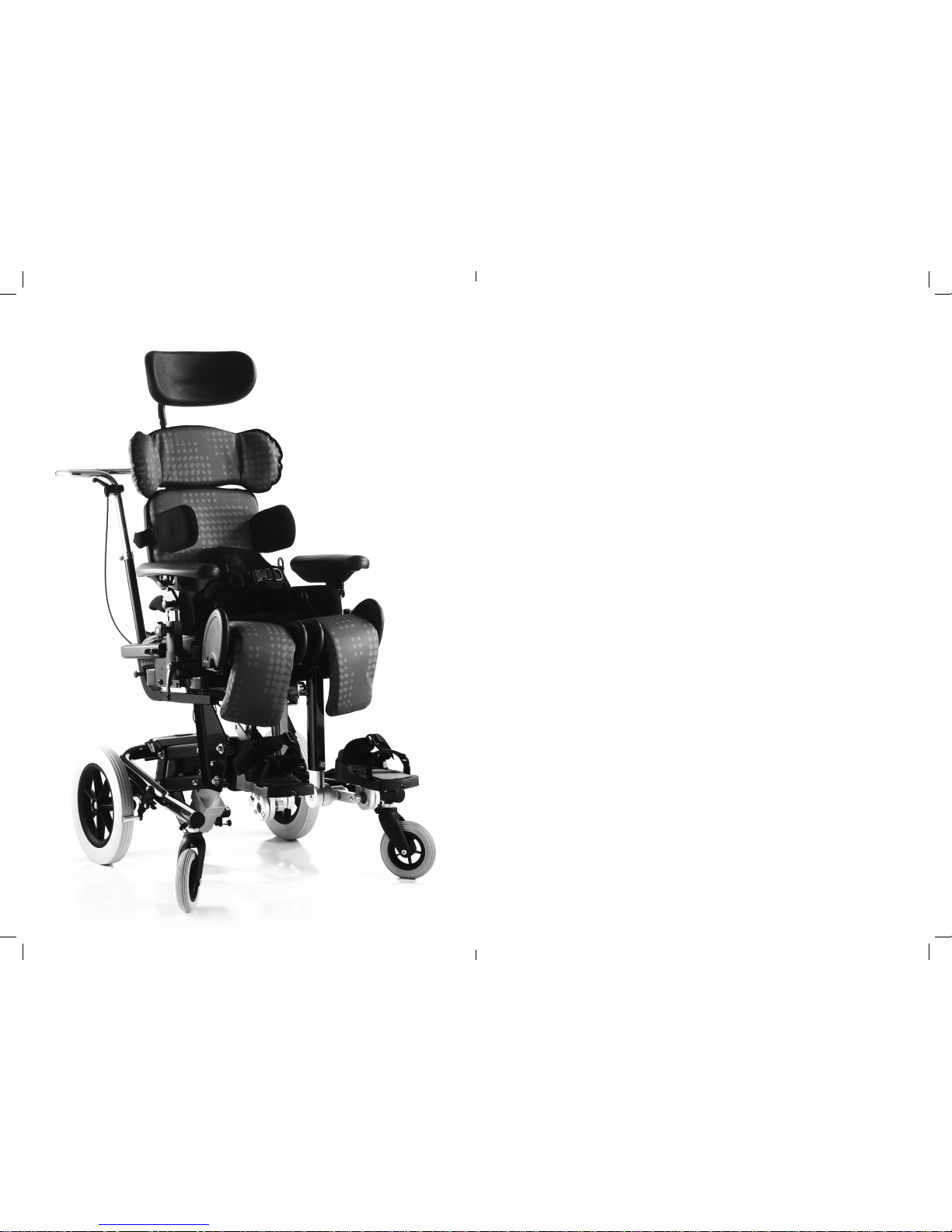
KIT Seating System
User Instructions
Contents
01 Intended use
02 Declaration of Conformity
03 Terms of Warranty
04 Product Record History
05 Product Training Records
06 Safety Information
07 How to unpack and assemble the seating system and fit the cushions
08 Clinical Setup for Postural Management
09 Cleaning and Care Information
10 Daily Product Inspection
11 Annual Product Inspection
12 Reissuing Leckey products
13 Product Servicing
14 Technical Information
The KIT Seating System has been
designed to offer a high level of
postural positioning while enabling
function and mobility. This manual
shows you how to quickly, easily
and safely make use of all the
functions. The instructions on
safety and maintenance will ensure
that you will enjoy the use of this
product for a long time.

1. Intended Use
The KIT Seating System is a seat that
has been designed for use by adults
and teenagers (from 12 years old) with
disabilities, in the home, in day centres,
in schools and outdoors, if used on a
mobility base. The seating system has a
maximum user weight of 75kg (165lbs).
The seating system is modular and
can be used with a choice of indoor or
outdoor chassis. The Hi-low chassis
has been designed for indoor use but
can also be used outdoors on an even
surface. The Hi-low chassis should never
be exposed to the elements as this may
corrode the metal components.
The Kit seat unit will interface with a
range of mobility bases, the details of
which can be found on our website,
www.leckey.com.
2. Declaration of Conformity
James Leckey Design Ltd as
manufacturer with sole responsibility
declares that the Kit Seating System
conforms to the requirements of the
93/42/EEC Guidelines, Medical Device
Regulations 2002 and EN 12182
Technical aids for disabled persons and
test methods.
3. Terms of Warranty
The warranty applies only when the
product is used according to the
specified conditions and for the intended
purposes, following all manufacturers’
recommendations (also see general
terms of sales, delivery and payment).
A three year warranty is provided on
all Leckey manufactured products and
components.
6.1 Always read instructions fully before
use.
6.2 Users should not be left unattended at
any time while using Leckey equipment.
6.3 Only use Leckey approved components
with your product. Never modify the
product in any way. Failure to follow
instructions may put the user or carer
at risk and will invalidate the warranty on
the product.
6.4 If in any doubt to the continued safe
use of your product or if any parts should
fail, please cease using the product and
contact our customer care team or local
dealer as soon as possible.
6.5 Carry out all positional adjustments
and ensure that they are securely fastened
before you put the user into this product.
Some adjustments may require the use of
a tool which is provided with each product.
Keep all tools out of reach of children.
6.6 When placing the user into a seating
system, for safety and positional reasons,
always secure the Pelvic Cradle first.
6.7 When the product is stationary ensure
that all wheels are locked and facing away
from the base as this will improve product
stability. This is especially important
when the tilt-in-space or back recline
facility is in use.
6.8 When the seat is in use on the Hi-low
chassis we do not recommend that the
users are moved over uneven surfaces
when in the equipment. All due care
and attention should be taken when
transporting the user in and out of the seat.
6.9 Never leave the product on a sloping
surface, greater than 5 degrees. Always
remember to lock all the wheels.
6.10 Only use the push handles to steer
and move the seat from one area to
another. Never use the tray for this
purpose.
6.11 The product contains components
which could present a choking hazard to
small children. Always check that locking
knobs and bolts within the user’s reach are
tightened and secure at all times.
6.12 Leckey products comply with fire
safety regulations in accordance with
EN12182. However the product contains
plastic components and therefore should
be kept away from all direct sources of
heat including naked flames, cigarettes,
electric and gas heaters.
6.13 Do not place hot items greater than
40º centigrade on the tray.
6.14 Clean the product regularly. Do
not use abrasive cleaners. Carry out
maintenance checks on a regular basis to
ensure your product is in good working
condition.
4. Product History Record
Your Leckey product is classified as
a Class 1 Medical Device and as such
should only be prescribed, set up or
reissued by a technically competent
person who has been trained in the use
of this product. Leckey recommend that
a written record is maintained to provide
details of all set ups, reissue inspections
and annual inspections of this product.
5. Product Training Record
(Parents, Teachers & Carers)
Your Leckey product is classified as
a Class 1 Medical Device and as such
Leckey recommend that parents,
teachers and carers using the equipment
should be made aware of the following
sections of this user manual by a
technically competent person:
Section 6
Safety Information
Section 8
Clinical Set up for Postural Management
Section 9
Cleaning and Care
Section 10
Daily Product Inspection
Leckey recommend that a written record
is maintained of all those who have
trained in the correct use of this product.
6 Safety Information

The KIT Seating System has been crash
tested and passed for use in vehicles.
It has been tested in its complete
configuration on a surrogate base with a
Leckey head support attached.
If the KIT Seating System is being used
in a vehicle, the following points must be
adhered to:
The KIT Seating System must be
positioned forward facing and used
with an Unwin Restraint System and a
Leckey head support, which should be
suitably positioned at all times during
transportation. The head support is
available as an optional accessory with
the KIT Seating System.
The KIT Seating System is crash tested
and meets the requirements of ISO 16840
part 4. The seat has also been tested and
meets the requirements of ISO 7176-19.
The crash tests were carried out using
a chest harness and Pelvic Cradle.
For further details please contact our
customer care team.
Important
If you are using the KIT Seating System
on a wheelchair base, please refer to the
wheelchair manufacturer’s handbook for
crash test details.
KIT Seating System –
Crash Test
6.15 When the product is not in use, it
should be stored in a dry place that is not
subjected to extremes of temperature. The
safe operating temperature range of the
product is +5 to +40 degrees Celsius.
6.16 Always check the ratchet handles on
the push handle are tightened securely
before you move the seat unit.
6.17 Before using the seating system
always check that the interface handle
on the seat unit is fully engaged with the
chassis and the locking pin is engaged.
If the handle is not engaged properly, the
seat unit may come loose and could cause
serious injury to the user or carer.
How to
unpack and
assemble
the seating
system and fit
the cushions
Check parts
Congratulations on purchasing your KIT
Seating System. When opening the box,
take care not to cut through the tape as
you may damage some of the parts
contained inside. All of the parts will be
contained in polythene bags with each
one clearly labelled. Carefully remove them
from the boxes and check all the parts you
have ordered.
Safety First
Keep polythene bags away from children.
Some of the accessories will need to be
assembled before you attach them to the
seat base you have purchased. If you are
fitting the seat to a mobility base, please
ensure you fit the interface plate to the
mobility base first. Instructions on how to
attach the interface to specific bases will
be provided with the interface plate. Once
you have checked all the components you
are ready to assemble the KIT Seating
System and attach it to its base. Please
follow the order suggested as it is often
easier to fit the cushions before assembling
the hardware.
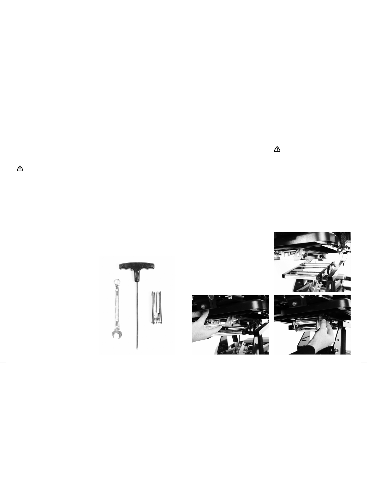
Tools
A number of the adjustments will require
the use of the multi-tool, T-bar allen key or
a 13mm spanner which are provided with
each seat.
7.1 Attaching the Seating
System to the Hi-low Chassis
Before attaching the seat unit to the
base raise the height of the chassis to its
maximum to reduce the risk of back strain.
Release the safety locking pin at the front
of the seat by pulling the pin (A) out and
rotating it through 90 degrees. Carefully
tilt the seat and place it onto the chassis,
locating the channel (B) at the rear of the
seat over the tube at the back of the chassis
(C).
Pull the handle (D) at the front of the seat
unit up and then pivot the seat down.
Once the seat is fully lowered, release the
handle and push it forward to ensure it has
fully engaged on the front tube. Rotate the
safety locking pin (A) so that it engages in
the front of the handle.
Always check the handle and locking pin
are fully engaged before you place the user
in the seating system. If the handle is not
engaged properly, the seat unit can come
loose and could cause serious injury to the
user or the carer.
D
A
A
B
C
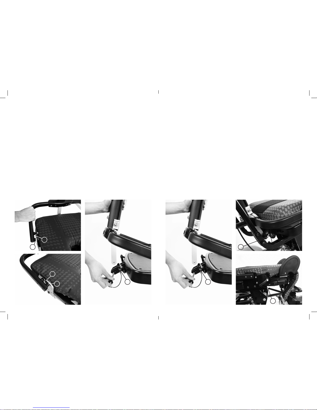
7.2 Removable
Backrest spine
The removable backrest spine will be detached
for shipping. Insert it into the side plates of the
seat base, slipping the front pin (A) into the
front slot (B) on both sides of the seat base.
Angle the spine back. Place the pin (C) through
the base of the spine.
C
7.4 Seat Base
Cushion
Fasten the two poppers (A) at the back of
the seatbase. Press the cushion down onto
the Velcro which is on the leg support ramps.
Loop the elastic over the hooks (B) on the
side of the seatbase.
7.3 Fixed Backrest
spine
If the fixed backrest spine option has been
ordered, simply rotate the backrest into the
vertical position and insert pin (A) through
the base of the spine.
A
B
AA
B
B
A
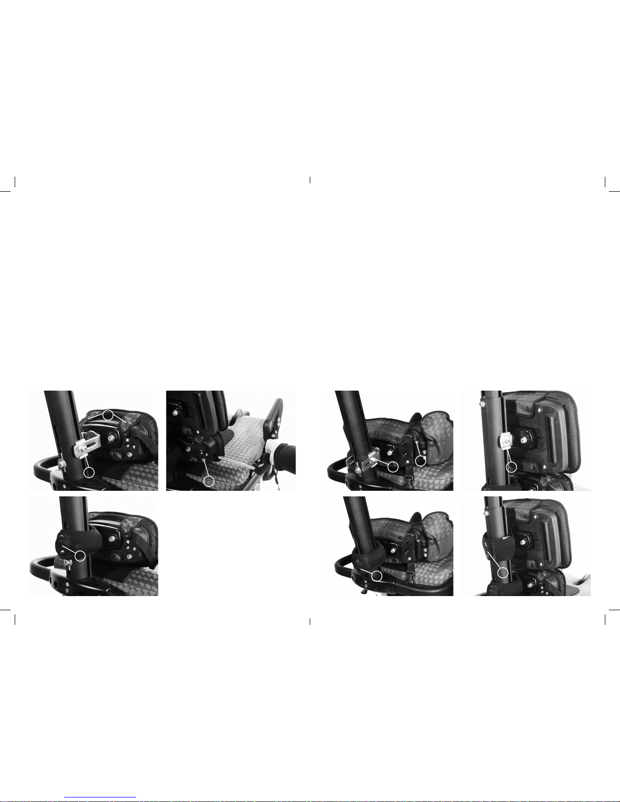
To fit the contoured sacral support cushion,
loosen the laterals using the screw (A) on
the hinge. Insert laterals into pockets and
fasten poppers on back.
Slide the support onto the lowest mounting
bracket on the backrest spine. Secure it
with a bolt (B) on either side. Cover the
bracket with a spine upholstery shroud (C).
7.7 Contoured sacral
support
A
B
C
7.8 Thoracic Support
Fit the cushion over the hardware and fasten
at the back with the poppers.
Slide the support onto the middle mounting
bracket on the backrest spine. Secure it with
a bolt (A) on either side. Cover the bracket
with a spine upholstery shroud (B).
A
B
Fit the sacral cushion over the hardware
and fasten at the back with the poppers.
The standard sacral support should
be attached with the double flaps (A)
at the top.
To attach the sacral support, slide the
support onto the lowest mounting bracket
on the backrest spine. Secure it with a bolt
(B) on either side. Cover the bracket with a
spine upholstery shroud (C).
7.5 Sacral support
B
A
A
C
To attach the hip laterals to the standard
sacral support, loosen the screw (A) and
insert the bar of the hip lateral into the hole
on the side of the sacral support. Tighten
the screw to secure.
To attach the hip lateral covers, slide the
cover over the lateral support.
7.6 Hip Laterals
7.9 Standard and
Complex Thoracic
Laterals
The standard and complex (horizontal
and vertical) laterals are attached in the
same way to the thoracic support. Before
attaching laterals, remove the thoracic
cushion. Before removing the bolt from the
bracket components, make a note of the
order in which the pieces fit together.
While holding the rest of the components
together, remove the bolt and washer (A)
with the Allen tool. Keeping the rest of the
components together, place the plastic
moulding into the slot (B). The bar should
go into the recess of the thoracic support.
Insert the bolt from the back and tighten.
Fit the lateral covers.
A
B
B
7.10 Angle
Adjustable Thoracic
Laterals
The angle adjustable laterals are attached to
the standard thoracic support. Position the
lateral brackets over the slot in the thoracic
supports and secure with two bolts (A). Fit
the cushion cover over the hardware and
secure with the poppers.
A
7.11 Shoulder Support
To fit the shoulder support cushion, loosen
the laterals using the screw (A) on the
hinge. Insert laterals into pockets and fasten
poppers on back.
Slide the support onto the top mounting
bracket on the backrest spine. Secure it
with a bolt (B) on either side. Cover the
bracket with a spine upholstery shroud (C).
B
A
C

7.13 Chest Pad
Screw the buckles onto the thoracic laterals.
Attach the chest pad to the buckles (A).
We recommend that lateral covers are
always fitted when using the chest pad. To
attach lateral covers, slide them over the
lateral ensuring that the slot
is on the outside to access the chest pad
attachment buckle.
7.12 Pelvic Cradle
Fasten the front buckle and side Velcro tabs
of the Pelvic Cradle. Ensure the “Back” label
(A) is against the backrest and the “Seat”
label (B) is on the seatbase cushion. Stick the
Velcro down to the seatbase cushion. Attach
the four side release buckles (C), two at the
back of the seatbase and two at the side.
B
B
C
C
A
A
7.14 Chest Harness
To attach the chest harness to the shoulder
section, first remove the cushion and plastic
cover. Feed the webbing into the holes (A)
in the mouldings and fasten with the nuts
and bolts provided. Attach the top straps
to these buckles. The lower straps attach
onto the buckles on the sacral support. If
the standard sacral support is used, attach
the webbing through the holes (B) at the top
of the moulding and fasten with the nuts
and bolts provided. If the contoured sacral
cushion is used, attach the webbing through
the holes (C) at the bottom of the moulding
and fasten with the nuts and bolts provided.
A

7.15 Headrest
To attach the head support (Leckey or
Otto Bock) slide the stem into the receiving
bracket (A) and secure by tightening the
screw (B).
The KIT Seating System has been designed
to interface with Whitmyer head supports
and a range of other supports that require
a box section receiving bracket. Insert the
Whitmyer interface bracket box section
into the top of the spine. Secure the head
support onto this bracket.
A
B
7.16 Femoral Gables 7.17 Foot Supports
Femoral gables are attached to the seat
base using bolts (A). There are two bolts for
each gable. Bolts should be firmly secured.
Loosen the leg support nuts (A) on the
underside of the seat base with a spanner.
Move the leg supports forward one at a
time. This makes it easier to insert the foot
supports. Open the screws (B) and slide in
the foot supports from the centre. Retighten
the screws. Reposition the leg supports and
retighten nuts.
Always make sure the foot supports are
attached securely.
A
B
A
A
Whitmyer bracket
Box section bracket

7.18 Attaching the
Sandal Straps
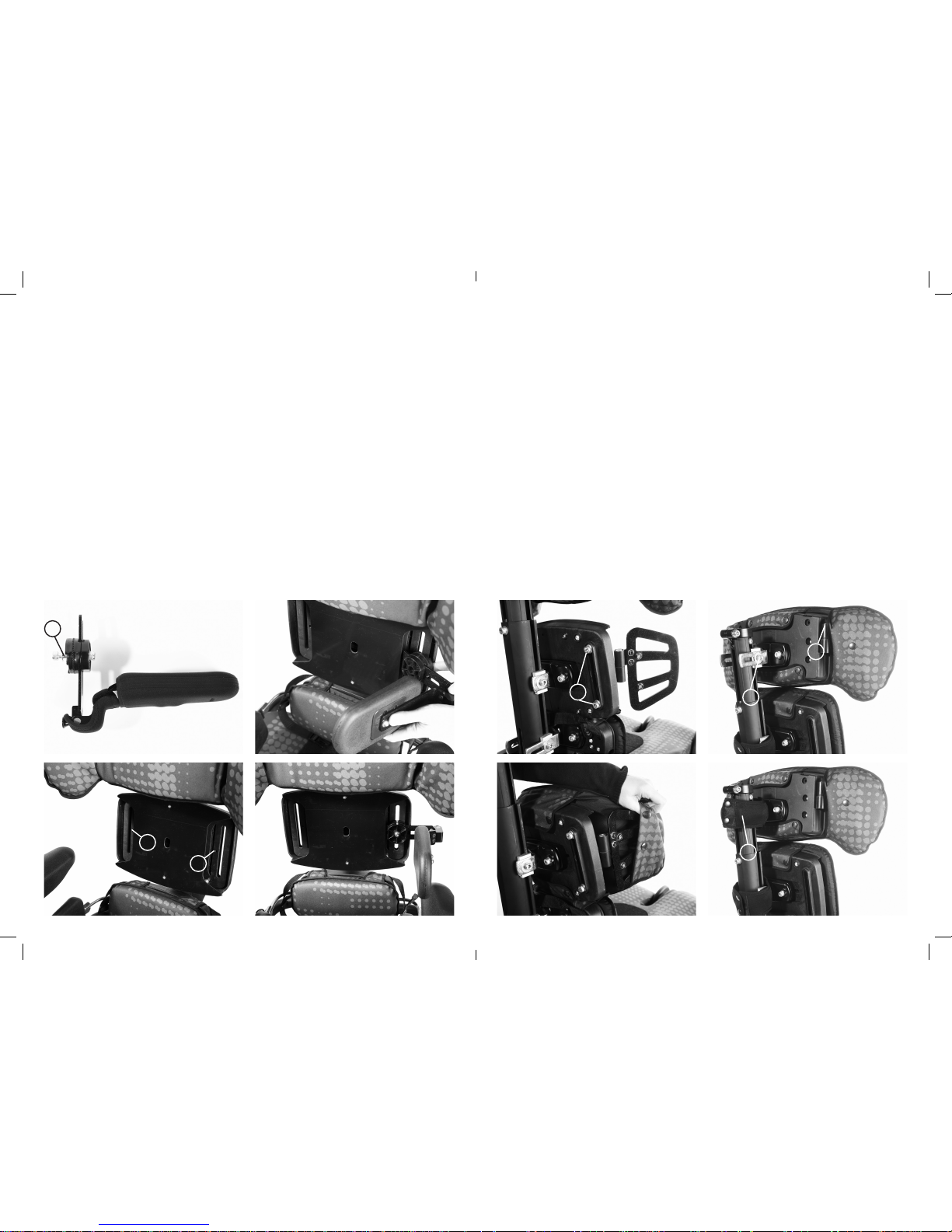
7.19 Armrests
Sandal straps can be attached to the foot
supports. Feed the back straps through the
slots in the rear of the sandals. Remove the
bolts on the underside of the sandals, thread
the bolts (A) through the ends of the straps
and refasten. The front straps are simply
fed from below through the front slots on
the sandals.
To attach the armrests, loosen the ratchet
handles (A) and insert the armrests with the
side with the adjustment knobs (B) facing
outwards.
A
B
7.20 Tray
Before attaching the tray, ensure the
armrests are at the same height and angle.
The tray is attached to the seat by inserting
the tray tubes through the centre of the
armrest. Tighten knob (A) to secure.
A
A
A

7.22 Setting up the
Push Handle
Unfold the push handle until straight and
secure in position with the spring popper (A)
at either side.
A
A
7.23 Interfaces for
wheelchair bases
The set up and attachment of the KIT
seat to any mobility base should be
completed by a technically competent
person who is familiar with the set up of
the mobility base.
The Leckey Mobility Base is built with an
interface which fits the KIT seat.
45cm Discovery Interface attachment to
18” (450mm) wide mobility base
The KIT seat can be easily attached to the
Discovery 45cm wide wheel base.
Please refer to specific assembly
instructions supplied with your interface
for correct positioning of your base. The
interface should be fitted by a qualified
technician who is technically competent
in the set up of the mobility base. The
position of the push handles, leg hangers
and armrests on the mobility base may need
to be adjusted depending on the size and
weight of the user to ensure the stability of
the seat.
Always refer to the mobility base
manufacturer’s guidelines for correct set
up, paying particular attention to product
centre of gravity and stability.
A thorough risk assessment should be
carried out when attaching the KIT Seat to
any mobility base not supplied by Leckey.
45cm Discovery BaseLeckey Mobility Base
7.21 Attaching the Foam
Spacer Pads
The foam spacer pads can be used to
support an obliquity or under the thighs.
They can be cut to size and attached using
Velcro.

The clinical set up of the product should
be completed by a technically and
clinically competent person who has been
trained in the use of the product. Leckey
recommend a written record is kept of all
clinical set ups for this product.
Leckey recommend that a full supine lying
and unsupported sitting assessment is
carried out prior to setting up the product.
Set the height and angle of each backrest
section (A), the seat depth (B) and the foot
support height (C) before placing the user
in the seat. These can be fine tuned when
the user is in the seat.
Clinical
Set up for
Postural
Management
C
B
A
To change the angle loosen the screw (A)
at the bottom of the backrest spine, adjust
to the required position and retighten the
screw securely.
The backrest angle can be adjusted with the
user in the seat.
Hold the backrest spine with one hand
while you adjust the back angle.
To adjust the overall height of the backrest
loosen the screw (A), adjust the shoulder
section to the required position and
retighten the screw securely. The height can
be fine tuned with the user in the seat.
Use caution when adjusting to minimum
setting as fingers could become trapped
between moving and static parts.
8.1 Backrest angle 8.2 Backrest Height
A
A
A

8.3 Pelvic Cradle 8.4 Gluteal ramp
When setting up the Pelvic Cradle for the
first time with the client in it, the Pelvic
Cradle should be flat and open before the
user is placed into the Kit Seating System.
All four side and back buckles should be
already attached to the seat. When the client
is placed in the seat, first fasten the buckle
(A) at the front of the Pelvic Cradle. Then
fasten the Velcro (B) at the sides to fit the
Pelvic Cradle to the user. Then adjust the
front and rear straps (C) and (D) to secure to
position the user’s pelvis.
After initial set up, only the front
buckle (A) needs to be released when
the user is transferred in or out of the KIT
Seating System.
Once a week, check that the Pelvic Cradle
has not become slack.
If a gluteal ramp (A) is required, it can be
attached by Velcro to the front of the
Pelvic Cradle before the user is placed into
the seat.
A
C
D
B
B
A
8.5 Sacral Support
The sacral support can be adjusted in a
number of ways - height, depth and angle.
To adjust the height or the depth, remove
the spine upholstery shroud and loosen the
two screws (A) on either side of the bracket.
Move the sacral support to the required
position, height and depth. Retighten the
screws and replace the spine upholstery
shroud.
To adjust the angle of the sacral support,
loosen both the screws (B) on the ball and
socket joint. Position the support at the
required angle. Retighten the screws.
A
BB

8.6 Hip Laterals
The hip laterals can be width and angle
adjusted to suit the user’s requirements.
Loosen the screws (A) at the back of the
sacral support. Move the hip laterals to
required position. Ideally the hip laterals
should always be rotated so they rest on
top of the seat cushion even if the backrest
or sacral support is angled. Once the hip
laterals are in position, retighten the screws
securely.
The laterals can also be angled to
help support abduction, adduction or
windsweeping.
To adjust the angle of the hip laterals loosen
the screw (B) on the hinge of the hip lateral.
Adjust to the required angle. Retighten the
screw. The pads can also be adjusted in
depth and a small degree of rotation by
loosening the screws (C) on the pad, sliding
it to the required position and retightening
the screws.
B
C
8.7 Contoured Sacral
Support
The contoured sacral support can be
adjusted in a number of ways - height, depth
and angle.
To adjust the height or the depth, remove
the spine upholstery shroud and loosen the
two screws (A) on either side of the bracket.
Move the sacral support to the required
position. Retighten the screws and replace
the spine upholstery shroud.
To adjust the angle of the sacral support,
loosen both the screws (B) on the ball and
socket joint. Position the support at the
required angle. Retighten the screws.
The lateral supports can be angle adjusted
to contour the pad and provide lateral pelvic
support. To angle, loosen screw C, set to
required angle and retighten securely.
A
A
C
B
C
C
B
B
A

8.8 Thoracic Support
The thoracic support can be adjusted in
a number of ways: height, lateral position
and angle.
To adjust the height, remove the spine
upholstery shroud, loosen the two screws
(A) on either side of the mounting bracket,
slide to the required position and then
retighten the screws securely.
To adjust the thoracic support laterally or in
angle, loosen both the screws (B) on the ball
and socket joint, position the support at the
required angle or lateral position and then
retighten the screws securely.
B
A
B
8.9 Standard and Complex
Thoracic Laterals
The standard and complex laterals,
horizontal and vertical options can be used
in whatever combination is most suited to
the user’s requirements. It is possible to
attach more than one lateral to the same
side of the thoracic support if required.
To adjust the height, width or angle of these
laterals, loosen the screw (A) on the lateral
mounting. Position the lateral at the required
height, width and angle. Retighten the screw.
The complex laterals can also be angled to
allow the pad to contour to the user’s shape.
To adjust loosen the screw (B) at the centre
of the pad, angle the pad to the required
position and retighten the screw.
All of the laterals can be flipped away to aid
transfer, by pulling the pin (C) at the back
and rotating the support out of the way.
A A
B
C

8.10 Angle Adjustable
Thoracic Laterals
To adjust the angle of the laterals, loosen
the screws (A) at the hinges. Contour the
laterals to the required angle. Retighten the
screws. The laterals have a small degree
of depth and rotational adjustment for
more proximal positioning. Loosen
screws (B) adjust the pad and retighten
the screws securely.
B
A
B
8.11 Shoulder Support
The shoulder support can be adjusted
in a number of ways – height, depth
and angle.
To adjust the height or the depth, remove
the spine upholstery shroud, loosen the two
screws (A) on either side of the mounting
bracket. Move the shoulder support to the
required position. Retighten the screws and
replace the spine upholstery shroud.
If further height adjustment is required,
please refer to the section on Backrest
Height. The Size 2 shoulder support can
also be attached to the Size 1 seat to further
increase the backrest height.
To adjust the angle of the whole shoulder
support, loosen both the screws (B) on the
ball and socket joint. Position the support at
the required angle. Retighten the screws.
B B
A
To adjust the angle of the wings of the
shoulder support, loosen both the screws (C)
at the hinges. Contour the shoulder support
to the required shape. Retighten the screws.
C

8.12 Headrest
8.13 Seat Base Depth
To adjust the height of the headrest, loosen
the screw (A) at the top of the backrest
spine. Position the headrest to the required
height to suit the user’s head position.
Retighten the screw.
To position the headrest, loosen one or both
of the plastic handles (B) at the hinges of the
headrest mounting. Position the headrest as
required. Retighten the screws.
To angle or rotate the head support, loosen
screws (C), set to required position and
retighten securely.
To adjust the seat base depth, loosen the
nuts (A) underneath the upper leg supports
with a spanner. Move the upper leg support
in or out to the required position and
retighten the nuts securely. It is possible to
upgrade the Size 1 seat base to achieve the
same seat depth size as the Size 2 seat.
To change the profile of the Profiling
Contoured Headrest, remove the cover,
loosen the screws (D), set to the required
position and retighten screws. Fit the
cover again.
To adjust the position of the Lateral
Headrest loosen screw (E), position as
required and retighten the screw.
A
A
B
C
A
8.14 Seat base – Upper Leg
Support Angle for Windsweep
-ing, Abduction or Adduction
To adjust the upper leg support angle
loosen the nuts (A) underneath the upper leg
supports, adjust to the required angle and
then retighten the nuts securely.
AA
D
E

8.15 Femoral Gables 8.16 Foot support height
Large and small femoral gables may be
used in any combination to suit the user’s
requirements, or they may be removed
altogether. To adjust the angle or width
of the femoral gables, loosen the screws
(A) and position as required. Retighten the
screws. There are two screws per femoral
gable.
To raise or lower the height of the foot
support, loosen the screw (A) adjust to the
required position and retighten the screw
securely.
A
8.17 Calf Support 8.18 Foot support - size
To adjust the calf support angle, loosen
the screw (A) at the top of the calf support,
move front or back to the required angle,
then retighten screw.
To change the size of the foot supports
to accommodate different shoe sizes,
loosen the screws (A) at the toes of the foot
supports. Adjust the foot support to the
required size. Retighten the screws.
Note: A 5mm tool is required.
A
A
A

8.19 Foot support - angle 8.20 Armrest
To change the angle of the complex foot
supports, loosen the three screws (A) on the
ball and socket joint on the underside of the
foot support. Change the angle to suit the
user’s requirements. Retighten the screws.
Note: A 5mm tool is required.
To flip away the complex or basic foot
supports, pull out the pin (B) at the back
of the sandals and rotate it through 90°.
Holding your thumb on C, slide the foot
support outwards, away from the centre line,
then flip up. The foot support locks in the
vertical position.
To adjust the armrest height, loosen the
knob (A), adjust to the required height and
retighten the knob. To adjust the angle pull
the pin (B) out and rotate the armrest to
the required position, then release the pin
ensuring the pin is securely located in one of
the holes.
Armrest pads can be moved forwards
or backwards by removing screws
(C), repositioning the armrest pad and
reattaching securely in position with the
screws.
A
B
A
B
B
B
C
C
C
C
8.21 Tilt-in-Space
The tilt-in-space can be angled when the
user is in the seat. Before you adjust the
tilt-in-space angle of the seat always ensure
that the Pelvic Cradle is secured, preventing
the user from sliding forwards in the seat.
To adjust the tilt angle, pull the lever on the
push handles, tilt the seat to the required
angle and remove your hand from the lever.
Always hold push handles securely before
using the tilt-in-space lever.
Ensure hands and body are not in contact
with seatbase during adjustment.
C

9 Cleaning & Care
Information
How to Maintain
When cleaning the product we recommend
that you use only warm water and a
nonabrasive detergent. Never use organic
solvents or dry cleaning fluids.
Upholstery and fabrics
1. The upholstery and fabrics can be
removed and machine washed and tumble
dried at a low setting. The standard covers
can be washed at 40ºC and the Infection
Control covers at 90ºC. Please remove the
foam before washing the following covers:
Shoulder support
Thoracic support
Sacral support
Contoured sacral support
Seat base.
All other soft upholstery can be placed
directly in the washing machine. Use a
wash bag to prevent covers being damaged
in the washing machine.
2. If the upholstery is to be cleaned in-situ,
the best cleaning method is a ‘wipe & dry’
technique.
3. Staining should be removed as quickly
as possible with absorbent cloth, towels or
a sponge. Routine soap and warm water
sponging is effective for ordinary soiling
and minor spills. Be careful not to over wet
the fabric, as this will cause the staining
to spread.
4. Always ensure the product is dry
before use.
Metal and plastic components
1. Soap and water or antibacterial spray can
be used for daily cleaning.
2. For deep cleaning a low pressure steam
cleaner can be used.
3. Do not use solvents to clean plastic or
metal components.
4. Make sure the product is dry before use.
8.22 Hi-low Chassis –
Height Adjustment
You can carry out this adjustment with
the user in the chair. If your chassis has
the foot pedal locking pin (A), disengage it
first. To unlock, pull the pin out and rotate
through 90 degrees. To adjust the height of
the hydraulic Hi-low chassis press the foot
lever (B) at the rear of the chassis. Once
you remove your foot from the pedal, the
seat will be fixed at this height. To lower the
height place foot under the pedal and lift up,
the seat height will gradually lower.
For safety always engage the pull pin (A)
after adjustment, if applicable.
To adjust the height of the powered base,
use the buttons on the handset. Before
the product is used for the first time, it
is recommended that the battery is fully
charged for 12 hours. To do this, plug the
adaptor into the mains socket and attach
the lead to the battery. Switch on the
mains power supply. When charged, switch
off the mains power supply, remove the
adaptor plug and disconnect the lead from
the battery. The battery charge should be
topped up each day until the green light on
the charge is illuminated. The chair can be
adjusted while attached to the mains.
Ensure that the product and user are
away from surrounding furnishings when
adjusting the height to prevent possible
collisions and injury to the user or damage
to the product.
A
B

10 Daily Product Inspection
(Therapists, parents & carers)
We recommend that daily visual checks of
the equipment are carried out by therapists,
carers or parents to ensure the product
is safe for use. The recommended daily
checks are detailed below.
Seat Checks
1. Ensure all adjustment knobs and bolts
are in place and secure.
2. Check all upholstery for signs of wear
and tear.
3. Check all Velcro strips and brush fluff to
ensure straps secure firmly.
4. Check all back support components
are secure.
Chassis Checks
1. Check all wheels are moving freely and
lock securely.
2. Check height adjustment is working and
pedal is locking.
3. Check tilt-in-space is working and
locking securely.
4. Check locking pin on the interface handle
is in its locked position.
If in any doubt to the continued safe
use of your Leckey product or if any
parts should fail, please cease using
the product and contact our customer
care team or your local dealer as soon
as possible.
11 Annual Product
Inspection
(Therapist, Technician, VIDA Product
Specialist, Dealer)
Leckey recommend that each product
should be subject to a detailed inspection
at least once a year and every time the
product is reissued for use. This inspection
should be carried out by a technically
competent person who has been trained
in the use of the product and should
include the following checks as a minimum
requirement.
1. Check all knobs, nuts, bolts and plastic
buckles are in place, replacing any missing
items. Paying particular attention to the
following items;
- Buckles and Velcro on Pelvic Cradle
- Seat interface handle locks and releases
- Tilt-in-space and height adjustment work
and lock securely
- All ball and socket joints lock securely,
shoulder, thoracic, sacral and foot
supports
- Backrest angle adjusts and locks securely
- Leg supports angle adjust and
lock securely
- Armrest height and angle adjust and
lock securely
- Head support locks securely
2. Lift the base to check each wheel
individually. Make sure they are moving
freely and remove any dirt from the rubber
wheels. Check that the brakes lock the
wheels securely.
3. Visually check the structure of the
product paying attention to weld points on
the frame ensuring there are no signs of
fatigue or cracking around the welds.
4. Leckey recommend that a written
record is maintained of all annual product
inspections.
If in any doubt to the continued safe
use of your Leckey product or if any
parts should fail, please cease using
the product and contact our customer
care team or your local dealer
as soon as possible.

12 Re-issuing Leckey
Products
Most Leckey products are assessed and
ordered to meet the needs of an individual
user. Before reissuing a product we
recommend that the therapist prescribing
the product has carried out an equipment
compatibility check for the new user and
has ensured that the product being
re-issued contains no modifications or
special attachments.
A detailed technical inspection should be
carried on the product prior to re-issuing.
This should be carried out by a technically
competent person who has been trained in
the use and inspection of the product.
Please refer to section 11 for the required
checks to be carried out.
Ensure the product has been cleaned
thoroughly in accordance with section 9
of this manual.
Ensure a copy of the user manual is
supplied with the product. A copy can be
downloaded from our website www.leckey.
com.
Leckey recommend that a written record
is maintained of all product inspections
carried out during the reissue of the
product.
If in any doubt to the continued safe
use of your Leckey product or if any
parts should fail, please cease using
the product and contact our customer
care team or your local dealer as soon
as possible.
13 Product Servicing
Servicing of all Leckey products should
only be carried out by technically
competent persons who have been trained
in the use of the product.
All international service enquiries
should be directed to the appropriate
Leckey distributor who will be delighted
to assist you. For further information on
Leckey distributors please visit our
website www.leckey.com.
14 Technical
Information
Product and Accessory Codes
133-1600-FIX Size 1 seat shell assembly
fixed backrest
133-1600-REM Size 1 seat shell assembly
removable backrest
139-2600-FIX Size 2 seat shell assembly
fixed backrest
139-2600-REM Size 2 seat shell assembly
removable backrest
133-404* Size 1 castellated foam seat
base cushion and cover
139-404* Size 2 castellated foam seat
base cushion and cover
133-405* Size 1 memory foam seat
base cushion and cover
139-405* Size 2 memory foam seat
base cushion and cover
133-611 Size 1 shoulder support
assembly
139-611 Size 2 shoulder support
assembly
133-400* Size 1 shoulder support
cushion and cover
139-400* Size 2 shoulder support
cushion and cover
133-605 Thoracic support assembly
133-401* Thoracic cushion and cover
133-619 Angle adjustable thoracic
laterals hardware
133-402* Angle adjustable thoracic
cushion and cover
133-612 Sacral support assembly
133-403* Sacral support cushion and
cover
133-604 Size 1 contoured sacral
support
133-400* Size 1 contoured sacral
support cushion and cover
133-1620 Lateral Headrest
For product codes marked with *, please
add the following colour option codes:
+10 Blue +11 Grey
+12 Purple +13 Grey Infection Control
Chassis
133-750 Kit Hi-low base – hydraulic
133-760 Kit Hi-low base – powered
133-770 Leckey Mobility base
133-740 45cm Discovery base and
mobility interface
Mobility Interface Options
139-726 45mm Discovery interface A
Accessories
133-728 Pelvic Cradle Size 0
133-729 Pelvic Cradle Size 1
133-730 Pelvic Cradle Size 2
133-731 Pelvic Cradle Size 3
133-608 Hip lateral pads (pair)
133-737 Pelvic Cradle gluteal ramp
133-609 Flip away laterals (single
without covers)
133-747 Lateral covers (single)
133-622-RH Flip away complex laterals -
horizontal right hand
(single with covers)
133-622-LH Flip away complex laterals -
horizontal left hand
(single with covers)
133-614-RH Flip away complex laterals vertical right hand
(single with covers)
133-614-LH Flip away complex laterals vertical left hand
(single with covers)
133-625 Chest pad
133-1626 Chest harness Size 1
133-2626 Chest harness Size 2
133-3626 Chest harness Size 3
133-627 Profiling contoured headrest
133-716 Profiling contoured headrest
cover
133-626 PU contoured headrest
133-735 Armrests (pair)
133-635 Tray – clear
133-624 Tray – grey
133-680 Padded tray insert
133-721 Leg straps (pair)
133-601 Femoral Gable Pack
(2 large and 2 small)
133-682 Large femoral gables – right
133-686 Large femoral gables – left
133-683 Small femoral gables – right
133-687 Small femoral gables – left
133-1005 Foam spacer pack
(for obliquity)
133-606 Foot supports - ball and
socket joints (pair)
133-607 Foot supports – basic (pair)
133-712 Sandal straps size 1
133-742 Sandal straps size 2
133-765 Spine upholstery shroud (set)
133-726 Lateral / bracket protector
covers (single)
133-749 Whitmyer bracket
133-745 Head Support bracket for 1/2”
and 15mm Box Section
WASH01 Washing machine bag

KIT seat dimensions Leckey Hi Low base options
LINAK Actuator specification
- 281209-01
Rated IP51
Duty Cycle Max 10% or 2 min continuous
use followed by 18 min not in use.
Ambient temp +5deg to +40deg C
Ambient Operating temp 22deg
Storage temp -40deg C to 70degC
Push Max 3500N
Pull Max 2000N
Self Lock at 3500N Push – 2000N Pull
Typical speed with full load 4.7mm/sec
Max amps at load of 3500N is 3.9 amps
Noise level dB(A) 48
Power input voltage 24v +- 10%
LINAK Battery Box - BA18021-00
Rated IP51
Ambient temp +5deg to 40deg C
Storage temp -20deg C to 60deg C
Rated Capacity 1.2 Ah 24v
Charging current is max 0.3A
Lead acid gel filled battery
LINAK Handset - HB41000-00004
Rated IP51
Control current 100mA per channel (Max)
Ambient temp +5deg to +40deg C
LINAK Battery Charger - CH01
Mains 100-240 VAC/50-60 Hz switch mode
power supply
Charging voltage 27.6 VDC +- 2%
Charging current Max 500mA
Green LED for power on
Yellow LED for charging function
Yellow LED turns into green when batteries
are fully charged.
LINAK products may be stored in nonheated storage facilities with humidity
between 0 and 100%, none condensing.
None condensing means that one should
not take a product from an ice cold
warehouse into a room with a temperature
of 20deg C; if this is done then moistness
will appear on the products.
Product sizing Size 1 Size 2
mm inches mm inches
Age range 12-18 yrs 16-adult
Stature range
Min 1400 55.1 1600 63.0
Max 1650 65.0 1850 73.0
Max user weight (kg/lbs) 75 165.0 75 165.0
Seat depth
Min 360 14.2 410 16.1
Max 480 18.9 560 22.0
Max windsweep accommodation 20° 20° 20° 20°
Max seat width - without laterals 430 16.9 430 16.9
Seat width - with hip laterals
Min 215 8.5 215 8.5
Max 370 14.6 370 14.6
Backrest height
Min 500 19.7 560 22.0
Max 620 24.4 675 26.6
Shoulder width
Min 190 7.5 260 10.2
Max 500 19.7 600 23.6
Chest width
Min 230 9.1 230 9.1
Max 380 15.0 380 15.0
Backrest angle 90°-120° 90°-120° 90°-120° 90°-120°
Seat to footplate
Min 330 13.0 330 13.0
Max 510 20.1 510 20.1
Armrest height
Min 265 10.4 265 10.4
Max 380 15.0 380 15.0
Tray size 630 x 460 24.8 X 18.1 630 X 460 24.8 X 18.1
Seat weight (seat & back) 20.5 Kg 45.1 Lbs 21 kg 46.2 Lbs
KIT Hi-low chassis
mm inches
Top of seat to floor
Min 460 18
Max 640 25
With handle folded down
Length 700 27.6
Width 620 24.4
Height 410 16

24 hour postural
care for babies,
kids & adults.
Sleeping, Sitting,
Standing, Walking,
Moving, Bathing,
Toileting.
Distributed by
A member of the
LS240-04
VIDA GLOBAL
19C Ballinderry Road
Lisburn, BT28 2SA
Northern Ireland,
United Kingdom
T: 028 9260 0750
F: 028 9260 0799
E: info@vidaglobal.co.uk
W: vidaglobal.co.uk
 Loading...