

Page 1

KIT Seating System
User Instructions
Il sistema di postura KIT
Istruzioni per l’uso
Das KIT-Sitzsystem
Bedienungsanleitung
Le système d’assise KIT
Consignes d’utilisation
El sistema KIT de asiento
Instrucciones de Usuario
Page 2

Page 3

Page 4

1. Intended Use
The KIT Seating System is a seat that
has been designed for use by adults
and teenagers (from 12 years old) with
disabilities, in the home, in day centres,
in schools and outdoors, if used on a
mobility base. The seating system has a
maximum user weight of 75kg (165lbs).
The seating system is modular and can be
used with a choice of indoor or outdoor
chassis. The Hi-low chassis has been
designed for indoor use but can also be
used outdoors on an even surface. The
Hi-low chassis should never be exposed
to the elements as this may corrode the
metal components.
The Kit seat unit will interface with a
range of mobility bases, the details of
which can be found on our website,
www.leckey.com.
2. Declaration of Conformity
James Leckey Design Ltd as manufacturer
with sole responsibility declares that
the Kit Seating System conforms to the
requirements of the 93/42/EEC Guidelines,
Medical Device Regulations 2002 and EN
12182 Technical aids for disabled persons
and test methods.
3. Terms of Warranty
The warranty applies only when the
product is used according to the
specified conditions and for the intended
purposes, following all manufacturers’
recommendations (also see general terms
of sales, delivery and payment). A two
year warranty is provided on all Leckey
manufactured products and components.
4. Product History Record
Your Leckey product is classified as a
Class 1 Medical Device and as such
should only be prescribed, set up or
reissued by a technically competent
person who has been trained in the use
of this product. Leckey recommend that
a written record is maintained to provide
details of all set ups, reissue inspections
and annual inspections of this product.
5. Product Training Record
(Parents, Teachers & Carers)
Your Leckey product is classified as a
Class 1 Medical Device and as such
Leckey recommend that parents, teachers
and carers using the equipment should
be made aware of the following sections
of this user manual by a technically
competent person:
Section 6
Safety Information
Section 8
Clinical Set up for Postural Management
Section 9
Cleaning and Care
Section 10
Daily Product Inspection
Leckey recommend that a written record
is maintained of all those who have trained
in the correct use of this product.
Page 5

6.1 Always read instructions fully before
use.
6.2 Users should not be left unattended at
any time while using Leckey equipment.
6.3 Only use Leckey approved components
with your product. Never modify the
product in any way. Failure to follow
instructions may put the user or carer
at risk and will invalidate the warranty on
the product.
6.4 If in any doubt to the continued safe
use of your product or if any parts should
fail, please cease using the product and
contact our customer services department
or local dealer as soon as possible.
6.5 Carry out all positional adjustments
and ensure that they are securely fastened
before you put the user into this product.
Some adjustments may require the use of
a tool which is provided with each product.
Keep all tools out of reach of children.
6.6 When placing the user into a seating
system, for safety and positional reasons,
always secure the Pelvic Cradle first.
6.7 When the product is stationary ensure
that all wheels are locked and facing away
from the base as this will improve product
stability. This is especially important
when the tilt in space or back recline
facility is in use.
6.8 When the seat is in use on the Hi-low
chassis we do not recommend that the
users are moved over uneven surfaces
when in the equipment. All due care
and attention should be taken when
transporting the user in and out of the seat.
6.9 Never leave the product on a sloping
surface, greater than 5 degrees. Always
remember to lock all the wheels.
6.10 Only use the push handles to steer
and move the seat from one area to
another. Never use the tray for this
purpose.
6.11 The product contains components
which could present a choking hazard to
small children. Always check that locking
knobs and bolts within the user’s reach are
tightened and secure at all times.
6.12 Leckey products comply with fire
safety regulations in accordance with
EN12182. However the product contains
plastic components and therefore should
be kept away from all direct sources of
heat including naked flames, cigarettes,
electric and gas heaters.
6.13 Do not place hot items greater than
40º centigrade on the tray.
6.14 Clean the product regularly. Do
not use abrasive cleaners. Carry out
maintenance checks on a regular basis to
ensure your product is in good working
condition.
6 Safety Information
Page 6

The KIT Seating System has been crash
tested and passed for use in vehicles.
It has been tested in its complete
configuration on a surrogate base with a
Leckey head support attached.
If the KIT Seating System is being used
in a vehicle, the following points must be
adhered to:
The KIT Seating System must be
positioned forward facing and used
with an Unwin Restraint System and a
Leckey head support, which should be
suitably positioned at all times during
transportation. The head support is
available as an optional accessory with
the KIT Seating System.
The KIT Seating System is crash tested
and meets the requirements of ISO 16840
part 4. The seat has also been tested and
meets the requirements of ISO 7176-19.
The crash tests were carried out using
a chest harness and Pelvic Cradle.
For further details please contact our
Customer Service Department.
Important
If you are using the KIT Seating System
on a wheelchair base, please refer to the
wheelchair manufacturer’s handbook for
crash test details.
KIT Seating System –
Crash Test
6.15 When the product is not in use, it
should be stored in a dry place that is not
subjected to extremes of temperature. The
safe operating temperature range of the
product is +5 to +40 degrees Celsius.
6.16 Always check the ratchet handles on
the push handle are tightened securely
before you move the seat unit.
6.17 Before using the seating system
always check that the interface handle
on the seat unit is fully engaged with the
chassis and the locking pin is engaged.
If the handle is not engaged properly, the
seat unit may come loose and could cause
serious injury to the user or carer.
Page 7

How to
unpack and
assemble
the seating
system and fit
the cushions
7
Page 8

Check parts
Congratulations on purchasing your KIT
Seating System. When opening the box,
take care not to cut through the tape as
you may damage some of the parts
contained inside. All of the parts will be
contained in polythene bags with each
one clearly labelled. Carefully remove them
from the boxes and check all the parts you
have ordered.
Safety First
Keep polythene bags away from children.
Some of the accessories will need to be
assembled before you attach them to the
seat base you have purchased. If you are
fitting the seat to a mobility base, please
ensure you fit the interface plate to the
mobility base first. Instructions on how to
attach the interface to specific bases will be
provided with the interface plate. Once you
have checked all the components you are
ready to assemble the KIT Seating System
and attach it to its base. Please follow the
order suggested as it is often easier to fit the
cushions before assembling the hardware.
Tools
A number of the adjustments will require
the use of the multi-tool, T-bar allen key or
a 13mm spanner which are provided with
each seat.
Page 9

7.1 Attaching the Seating
System to the Hi-low Chassis
Before attaching the seat unit to the base
raise the height of the chassis to its maximum
to reduce the risk of back strain.
Release the safety locking pin at the front of
the seat by pulling the pin (A) out and rotating
it through 90 degrees. Carefully tilt the seat
and place it onto the chassis, locating the
channel (B) at the rear of the seat over the
tube at the back of the chassis (C).
Pull the handle (D) at the front of the seat
unit up and then pivot the seat down.
Once the seat is fully lowered, release the
handle and push it forward to ensure it has
fully engaged on the front tube. Rotate the
safety locking pin (A) so that it engages in the
front of the handle.
Always check the handle and locking pin
are fully engaged before you place the user
in the seating system. If the handle is not
engaged properly, the seat unit can come
loose and could cause serious injury to the
user or the carer.
D
A
A
B
C
Page 10

7.2 Removable
Backrest spine
The removable backrest spine will be
detached for shipping. Insert it into the side
plates of the seat base, slipping the front pin
(A) into the front slot (B) on both sides of the
seat base. Angle the spine back. Place the
pin (C) through the base of the spine.
C
A
B
B
A
Page 11

7.4 Seat Base
Cushion
Fasten the two poppers (A) at the back of the
seatbase. Press the cushion down onto the
Velcro which is on the leg support ramps.
Loop the elastic over the hooks (B) on the
side of the seatbase.
7.3 Fixed Backrest
spine
If the fixed backrest spine option has been
ordered, simply rotate the backrest into the
vertical position and insert pin (A) through the
base of the spine.
A
B
A
Page 12

Fit the sacral cushion over the hardware and
fasten at the back with the poppers. The
standard sacral support should be attached
with the double flaps (A) at the top.
To attach the sacral support, slide the
support onto the lowest mounting bracket on
the backrest spine. Secure it with a bolt (B)
on either side. Cover the bracket with a spine
upholstery shroud (C).
7.5 Sacral support
B
A
A
C
To attach the hip laterals to the standard
sacral support, loosen the screw (A) and
insert the bar of the hip lateral into the hole
on the side of the sacral support. Tighten the
screw to secure.
To attach the hip lateral covers, slide the
cover over the lateral support.
7.6 Hip Laterals
Page 13

To fit the contoured sacral support cushion,
loosen the laterals using the screw (A) on the
hinge. Insert laterals into pockets and fasten
poppers on back.
Slide the support onto the lowest mounting
bracket on the backrest spine. Secure it with
a bolt (B) on either side. Cover the bracket
with a spine upholstery shroud (C).
7.7 Contoured sacral
support
A
B
C
7.8 Thoracic Support
Fit the cushion over the hardware and fasten
at the back with the poppers.
Slide the support onto the middle mounting
bracket on the backrest spine. Secure it with
a bolt (A) on either side. Cover the bracket
with a spine upholstery shroud (B).
A
B
Page 14
7.9 Standard and
Complex Thoracic
Laterals
The standard and complex (horizontal and
vertical) laterals are attached in the same
way to the thoracic support. Before attaching
laterals, remove the thoracic cushion.
Before removing the bolt from the bracket
components, make a note of the order in
which the pieces fit together.
While holding the rest of the components
together, remove the bolt and washer (A)
with the Allen tool. Keeping the rest of the
components together, place the plastic
moulding into the slot (B). The bar should go
into the recess of the thoracic support. Insert
the bolt from the back and tighten. Fit the
lateral covers.
A
B
B
Page 15

7.10 Angle
Adjustable Thoracic
Laterals
The angle adjustable laterals are attached to
the standard thoracic support. Position the
lateral brackets over the slot in the thoracic
supports and secure with two bolts (A).
Fit the cushion cover over the hardware and
secure with the poppers.
A
7.11 Shoulder Support
To fit the shoulder support cushion, loosen
the laterals using the screw (A) on the hinge.
Insert laterals into pockets and fasten poppers
on back.
Slide the support onto the top mounting
bracket on the backrest spine. Secure it with
a bolt (B) on either side. Cover the bracket
with a spine upholstery shroud (C).
B
A
C
Page 16

7.13 Chest Pad
Screw the buckles onto the thoracic laterals.
Attach the chest pad to the buckles (A).
We recommend that lateral covers are always
fitted when using the chest pad. To attach
lateral covers, slide them over the lateral
ensuring that the slot is on the outside to
access the chest pad attachment buckle.
7.12 Pelvic Cradle
Fasten the front buckle and side Velcro tabs of
the Pelvic Cradle. Ensure the “Back” label (A)
is against the backrest and the “Seat” label (B)
is on the seatbase cushion. Stick the Velcro
down to the seatbase cushion. Attach the four
side release buckles (C), two at the back of the
seatbase and two at the side.
B
C
A
A
Page 17

B
C
7.14 Chest Harness
To attach the chest harness to the shoulder
section, first remove the cushion and plastic
cover. Feed the webbing into the holes (A) in
the mouldings and fasten with the nuts and
bolts provided. Attach the top straps to these
buckles. The lower straps attach onto the
buckles on the sacral support. If the standard
sacral support is used, attach the webbing
through the holes (B) at the top of the
moulding and fasten with the nuts and bolts
provided. If the contoured sacral cushion is
used, attach the webbing through the holes
(C) at the bottom of the moulding and fasten
with the nuts and bolts provided.
A
Page 18

7.15 Headrest
To attach the head support (Leckey or
Otto Bock) slide the stem into the receiving
bracket (A) and secure by tightening the
screw (B).
The KIT Seating System has been designed to
interface with a range of other supports that
require a box section receiving bracket. Insert
the bracket box section into the top
of the spine. Secure the head support onto
this bracket.
A
B
Box section bracket
Page 19

7.16 Femoral Gables 7.17 Foot Supports
Femoral gables are attached to the seat base
using bolts (A). There are two bolts for each
gable. Bolts should be firmly secured.
Loosen the leg support nuts (A) on the
underside of the seat base with a spanner.
Move the leg supports forward one at a
time. This makes it easier to insert the foot
supports. Open the screws (B) and slide in
the foot supports from the centre. Retighten
the screws. Reposition the leg supports and
retighten nuts.
Always make sure the foot supports are
attached securely.
A
B
A
A
Page 20

7.18 Attaching the
Sandal Straps
Sandal straps can be attached to the foot
supports. Feed the back straps through the
slots in the rear of the sandals. Remove the
bolts on the underside of the sandals, thread
the bolts (A) through the ends of the straps
and refasten. The front straps are simply
fed from below through the front slots on
the sandals.
A
A
Page 21

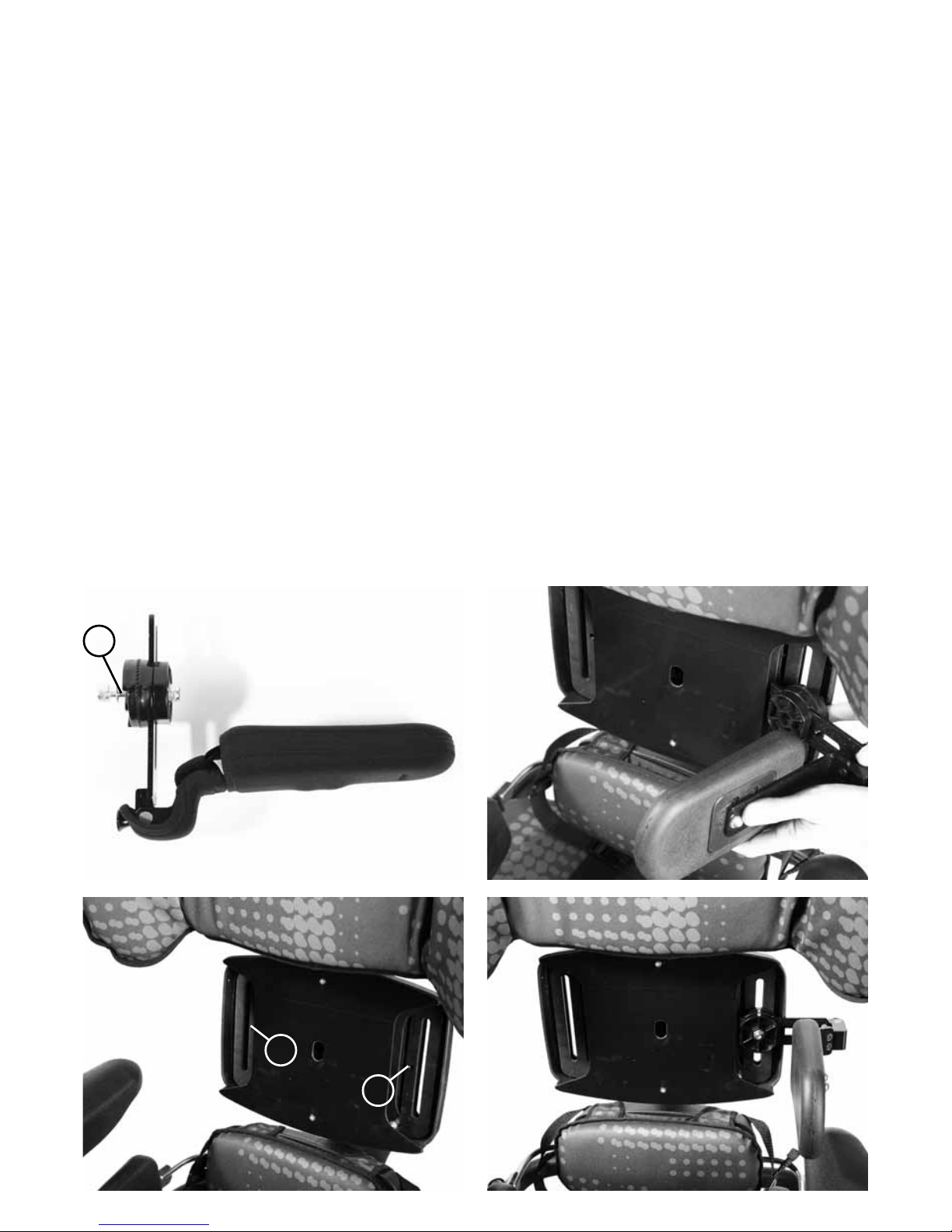
7.19 Armrests
To attach the armrests, loosen the ratchet
handles (A) and insert the armrests with
the side with the adjustment knobs (B)
facing outwards.
A
B
7.20 Tray
Before attaching the tray, ensure the armrests
are at the same height and angle. The tray
is attached to the seat by inserting the tray
tubes through the centre of the armrest.
Tighten knob (A) to secure.
A
Page 22

7.22 Setting up the
Push Handle
Unfold the push handle until straight and
secure in position with the spring popper (A)
at either side.
A
A
7.21 Attaching the Foam
Spacer Pads
The foam spacer pads can be used to
support an obliquity or under the thighs. They
can be cut to size and attached using Velcro.
Page 23

7.23 Interfaces for
wheelchair bases
The set up and attachment of the KIT
seat to any mobility base should be
completed by a technically competent
person who is familiar with the set up of
the mobility base.
The Leckey Mobility Base is built with an
interface which fits the KIT seat.
45cm Discovery Interface attachment to
18” (450mm) wide mobility base
The KIT seat can be easily attached to the
Discovery 45cm wide wheel base.
Please refer to specific assembly instructions
supplied with your interface for correct
positioning of your base. The interface
should be fitted by a qualified technician
who is technically competent in the set up
of the mobility base. The position of the
push handles, leg hangers and armrests on
the mobility base may need to be adjusted
depending on the size and weight of the user
to ensure the stability of the seat.
Always refer to the mobility base
manufacturer’s guidelines for correct set
up, paying particular attention to product
centre of gravity and stability.
A thorough risk assessment should be
carried out when attaching the KIT Seat to
any mobility base not supplied by Leckey.
45cm Discovery BaseLeckey Mobility Base
Page 24

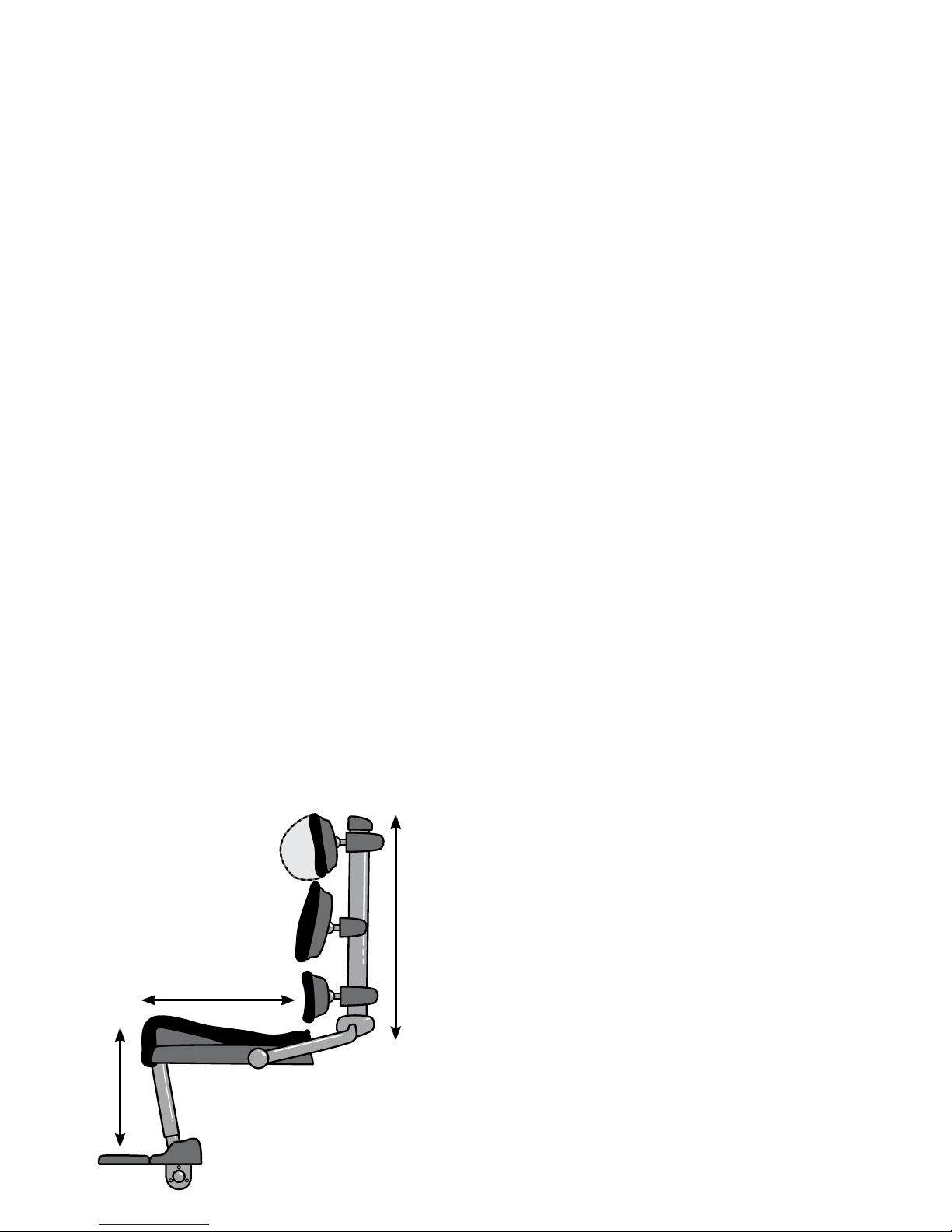
The clinical set up of the product should
be completed by a technically and clinically
competent person who has been trained in
the use of the product. Leckey recommend
a written record is kept of all clinical set
ups for this product.
Leckey recommend that a full supine lying
and unsupported sitting assessment is
carried out prior to setting up the product.
Set the height and angle of each backrest
section (A), the seat depth (B) and the foot
support height (C) before placing the user
in the seat. These can be fine tuned when
the user is in the seat.
Clinical
Set up for
Postural
Management
8
C
B
A
Page 25

To change the angle loosen the screw (A) at
the bottom of the backrest spine, adjust to
the required position and retighten the screw
securely.
The backrest angle can be adjusted with the
user in the seat.
Hold the backrest spine with one hand
while you adjust the back angle.
To adjust the overall height of the backrest
loosen the screw (A), adjust the shoulder
section to the required position and retighten
the screw securely. The height can be fine
tuned with the user in the seat.
Use caution when adjusting to minimum
setting as fingers could become trapped
between moving and static parts.
8.1 Backrest angle 8.2 Backrest Height
A
A
A
Page 26

8.3 Pelvic Cradle 8.4 Gluteal ramp
When setting up the Pelvic Cradle for the first
time with the client in it, the Pelvic Cradle
should be flat and open before the user is
placed into the Kit Seating System. All four
side and back buckles should be already
attached to the seat. When the client is placed
in the seat, first fasten the buckle (A) at the
front of the Pelvic Cradle. Then fasten the
Velcro (B) at the sides to fit the Pelvic Cradle
to the user. Then adjust the front and rear
straps (C) and (D) to secure to position the
user’s pelvis.
After initial set up, only the front
buckle (A) needs to be released when
the user is transferred in or out of the KIT
Seating System.
Once a week, check that the Pelvic Cradle
has not become slack.
If a gluteal ramp (A) is required, it can be
attached by Velcro to the front of the
Pelvic Cradle before the user is placed into
the seat.
A
C
D
B
B
A
Page 27

8.5 Sacral Support
The sacral support can be adjusted in a
number of ways - height, depth and angle.
To adjust the height or the depth, remove the
spine upholstery shroud and loosen the two
screws (A) on either side of the bracket. Move
the sacral support to the required position,
height and depth. Retighten the screws and
replace the spine upholstery shroud.
To adjust the angle of the sacral support,
loosen both the screws (B) on the ball and
socket joint. Position the support at the
required angle. Retighten the screws.
A
BB
Page 28

8.6 Hip Laterals
The hip laterals can be width and angle
adjusted to suit the user’s requirements.
Loosen the screws (A) at the back of the
sacral support. Move the hip laterals to
required position. Ideally the hip laterals
should always be rotated so they rest on top
of the seat cushion even if the backrest or
sacral support is angled. Once the hip laterals
are in position, retighten the screws securely.
The laterals can also be angled to
help support abduction, adduction or
windsweeping.
To adjust the angle of the hip laterals loosen
the screw (B) on the hinge of the hip lateral.
Adjust to the required angle. Retighten the
screw. The pads can also be adjusted in
depth and a small degree of rotation by
loosening the screws (C) on the pad, sliding it
to the required position and retightening the
screws.
B
C
A
C
B
A
Page 29

8.7 Contoured Sacral
Support
The contoured sacral support can be
adjusted in a number of ways - height, depth
and angle.
To adjust the height or the depth, remove the
spine upholstery shroud and loosen the two
screws (A) on either side of the bracket. Move
the sacral support to the required position.
Retighten the screws and replace the spine
upholstery shroud.
To adjust the angle of the sacral support,
loosen both the screws (B) on the ball and
socket joint. Position the support at the
required angle. Retighten the screws.
The lateral supports can be angle adjusted
to contour the pad and provide lateral pelvic
support. To angle, loosen screw C, set to
required angle and retighten securely.
A
C
C
B
B
Page 30

8.8. Thoracic Support
The thoracic support can be adjusted in
a number of ways: height, lateral position
and angle.
To adjust the height, remove the spine
upholstery shroud, loosen the two screws (A)
on either side of the mounting bracket, slide
to the required position and then retighten
the screws securely.
To adjust the thoracic support laterally or in
angle, loosen both the screws (B) on the ball
and socket joint, position the support at the
required angle or lateral position and then
retighten the screws securely.
B
A
B
Page 31

8.9 Standard and Complex
Thoracic Laterals
The standard and complex laterals, horizontal
and vertical options can be used in whatever
combination is most suited to the user’s
requirements. It is possible to attach more
than one lateral to the same side of the
thoracic support if required.
To adjust the height, width or angle of these
laterals, loosen the screw (A) on the lateral
mounting. Position the lateral at the required
height, width and angle. Retighten the screw.
The complex laterals can also be angled to
allow the pad to contour to the user’s shape.
To adjust loosen the screw (B) at the centre
of the pad, angle the pad to the required
position and retighten the screw.
All of the laterals can be flipped away to aid
transfer, by pulling the pin (C) at the back and
rotating the support out of the way.
A A
B
C
Page 32

8.10 Angle Adjustable
Thoracic Laterals
To adjust the angle of the laterals, loosen the
screws (A) at the hinges. Contour the laterals
to the required angle. Retighten the screws.
The laterals have a small degree of depth
and rotational adjustment for more proximal
positioning. Loosen screws (B) adjust the pad
and retighten the screws securely.
B
A
B
8.11 Shoulder Support
The shoulder support can be adjusted
in a number of ways – height, depth
and angle.
To adjust the height or the depth, remove
the spine upholstery shroud, loosen the two
screws (A) on either side of the mounting
bracket. Move the shoulder support to the
required position. Retighten the screws and
replace the spine upholstery shroud.
If further height adjustment is required, please
refer to the section on Backrest Height.
The Size 2 shoulder support can also be
attached to the Size 1 seat to further increase
the backrest height.
A
Page 33

To adjust the angle of the whole shoulder
support, loosen both the screws (B) on the
ball and socket joint. Position the support at
the required angle. Retighten the screws.
B B
To adjust the angle of the wings of the
shoulder support, loosen both the screws (C)
at the hinges. Contour the shoulder support to
the required shape. Retighten the screws.
C
Page 34

8.12 Headrest 8.13 Seat Base Depth
To adjust the height of the headrest, loosen
the screw (A) at the top of the backrest spine.
Position the headrest to the required
height to suit the user’s head position.
Retighten the screw.
To position the headrest, loosen one or both
of the plastic handles (B) at the hinges of the
headrest mounting. Position the headrest as
required. Retighten the screws.
To angle or rotate the head support, loosen
screws (C), set to required position and
retighten securely.
To change the profile of the Profiling
Contoured Headrest, remove the cover,
loosen the screws (D), set to the required
position and retighten screws. Fit the
cover again.
To adjust the seat base depth, loosen the nuts
(A) underneath the upper leg supports with a
spanner. Move the upper leg support in or out
to the required position and retighten the nuts
securely. It is possible to upgrade the Size 1
seat base to achieve the same seat depth size
as the Size 2 seat.
A
A
B
C
A
D
Page 35

8.14 Seat base – Upper Leg Support Angle for
Windsweeping, Abduction or Adduction
To adjust the upper leg support angle
loosen the nuts (A) underneath the upper leg
supports, adjust to the required angle and
then retighten the nuts securely.
AA
Page 36

8.15 Femoral Gables 8.16 Foot support height
Large and small femoral gables may be
used in any combination to suit the user’s
requirements, or they may be removed
altogether. To adjust the angle or width of
the femoral gables, loosen the screws (A) and
position as required. Retighten the screws.
There are two screws per femoral gable.
To raise or lower the height of the foot
support, loosen the screw (A) adjust to the
required position and retighten the screw
securely.
A
A
Page 37

8.17 Calf Support 8.18 Foot support - size
To adjust the calf support angle, loosen the
screw (A) at the top of the calf support, move
front or back to the required angle, then
retighten screw.
To change the size of the foot supports to
accommodate different shoe sizes, loosen the
screws (A) at the toes of the foot supports.
Adjust the foot support to the required size.
Retighten the screws.
Note: A 5mm tool is required.
A
A
Page 38

8.19 Foot support - angle
(Complex supports only)
To change the angle of the foot supports,
loosen the three screws (A) on the ball and
socket joint on the underside of the foot
support. Change the angle to suit the user’s
requirements. Retighten the screws.
Note: A 5mm tool is required.
To flip away the foot supports, pull out the
pin (B) at the back of the sandals and rotate
it through 90°. Holding your thumb on C,
slide the foot support outwards, away from
the centre line, then flip up. The foot support
locks in the vertical position.
A
B
B
B
C
C
C
C
Page 39

8.20 Armrest
To adjust the armrest height, loosen the knob
(A), adjust to the required height and retighten
the knob. To adjust the angle pull the pin (B)
out and rotate the armrest to the required
position, then release the pin ensuring the pin
is securely located in one of the holes.
Armrest pads can be moved forwards
or backwards by removing screws (C),
repositioning the armrest pad and reattaching
securely in position with the screws.
A
B
8.21 Tilt in Space
The tilt in space can be angled when the
user is in the seat. Before you adjust the tilt
in space angle of the seat always ensure that
the Pelvic Cradle is secured, preventing the
user from sliding forwards in the seat.
To adjust the tilt angle, pull the lever on the
push handles, tilt the seat to the required
angle and remove your hand from the lever.
Always hold push handles securely before
using the tilt in space lever.
C
Page 40

8.22 Hi-low Chassis –
Height Adjustment
You can carry out this adjustment with the
user in the chair. If your chassis has the foot
pedal locking pin (A), disengage it first. To
unlock, pull the pin out and rotate through 90
degrees. To adjust the height of the hydraulic
Hi-low chassis press the foot lever (B) at the
rear of the chassis. Once you remove your
foot from the pedal, the seat will be fixed at
this height. To lower the height place foot
under the pedal and lift up, the seat height will
gradually lower.
For safety always engage the pull pin (A)
after adjustment, if applicable.
To adjust the height of the powered base,
use the buttons on the handset. Before
the product is used for the first time, it is
recommended that the battery is fully charged
for 12 hours. To do this, plug the adaptor
into the mains socket and attach the lead
to the battery. Switch on the mains power
supply. When charged, switch off the mains
power supply, remove the adaptor plug and
disconnect the lead from the battery. The
battery charge should be topped up each
day until the green light on the charge is
illuminated. The chair can be adjusted while
attached to the mains.
Ensure that the product and user are
away from surrounding furnishings when
adjusting the height to prevent possible
collisions and injury to the user or damage
to the product.
A
B
Page 41

9 Cleaning & Care
Information
How to Maintain
When cleaning the product we recommend
that you use only warm water and a
nonabrasive detergent. Never use organic
solvents or dry cleaning fluids.
Upholstery and fabrics
1. The upholstery and fabrics can be
removed and machine washed and tumble
dried at a low setting. The standard covers
can be washed at 40ºC and the Infection
Control covers at 90ºC. Please remove the
foam before washing the following covers:
Shoulder support
Thoracic support
Sacral support
Contoured sacral support
Seat base.
All other soft upholstery can be placed
directly in the washing machine. Use a wash
bag to prevent covers being damaged in the
washing machine.
2. If the upholstery is to be cleaned in-situ,
the best cleaning method is a ‘wipe & dry’
technique.
3. Staining should be removed as quickly
as possible with absorbent cloth, towels or
a sponge. Routine soap and warm water
sponging is effective for ordinary soiling and
minor spills. Be careful not to over wet the
fabric, as this will cause the staining
to spread.
4. Always ensure the product is dry
before use.
Metal and plastic components
1. Soap and water or antibacterial spray can
be used for daily cleaning.
2. For deep cleaning a low pressure steam
cleaner can be used.
3. Do not use solvents to clean plastic or
metal components.
4. Make sure the product is dry before use.
Page 42

10 Daily Product Inspection
(Therapists, parents & carers)
We recommend that daily visual checks of
the equipment are carried out by therapists,
carers or parents to ensure the product is
safe for use. The recommended daily checks
are detailed below.
Seat Checks
1. Ensure all adjustment knobs and bolts
are in place and secure.
2. Check all upholstery for signs of wear
and tear.
3. Check all Velcro strips and brush fluff to
ensure straps secure firmly.
4. Check all back support components
are secure.
Chassis Checks
1. Check all wheels are moving freely and
lock securely.
2. Check height adjustment is working and
pedal is locking.
3. Check tilt in space is working and
locking securely.
4. Check locking pin on the interface handle
is in its locked position.
If in any doubt to the continued safe
use of your Leckey product or if any
parts should fail, please cease using the
product and contact our customer service
department or your local dealer as soon
as possible.
11 Annual Product
Inspection
(Therapist, Technician, Leckey Product
Advisor, Dealer)
Leckey recommend that each product should
be subject to a detailed inspection at least
once a year and every time the product is
reissued for use. This inspection should
be carried out by a technically competent
person who has been trained in the use of
the product and should include the following
checks as a minimum requirement.
1. Check all knobs, nuts, bolts and plastic
buckles are in place, replacing any missing
items. Paying particular attention to the
following items;
- Buckles and Velcro on Pelvic Cradle
- Seat interface handle locks and releases
- Tilt in space and height adjustment work
and lock securely
- All ball and socket joints lock securely,
shoulder, thoracic, sacral and foot supports
- Backrest angle adjusts and locks securely
- Leg supports angle adjust and
lock securely
- Armrest height and angle adjust and
lock securely
- Head support locks securely
2. Lift the base to check each wheel
individually. Make sure they are moving
freely and remove any dirt from the rubber
wheels. Check that the brakes lock the
wheels securely.
Page 43

3. Visually check the structure of the product
paying attention to weld points on the frame
ensuring there are no signs of fatigue or
cracking around the welds.
4. Leckey recommend that a written record is
maintained of all annual product inspections.
If in any doubt to the continued safe
use of your Leckey product or if any
parts should fail, please cease using the
product and contact our customer
service department or your local dealer
as soon as possible.
12 Re-issuing Leckey
Products
Most Leckey products are assessed and
ordered to meet the needs of an individual
user. Before reissuing a product we
recommend that the therapist prescribing
the product has carried out an equipment
compatibility check for the new user and
has ensured that the product being
re-issued contains no modifications or
special attachments.
A detailed technical inspection should be
carried on the product prior to re-issuing.
This should be carried out by a technically
competent person who has been trained in
the use and inspection of the product.
Please refer to section 11 for the required
checks to be carried out.
Ensure the product has been cleaned
thoroughly in accordance with section 9
of this manual.
Ensure a copy of the user manual is supplied
with the product. A copy can be downloaded
from our website www.leckey.com.
Leckey recommend that a written record is
maintained of all product inspections carried
out during the reissue of the product.
If in any doubt to the continued safe
use of your Leckey product or if any
parts should fail, please cease using the
product and contact our customer service
department or your local dealer as soon
as possible.
Page 44

13 Product Servicing
Servicing of all Leckey products should only
be carried out by technically competent
persons who have been trained in the use of
the product.
In the UK & ROI please contact the Leckey
Service Centre on UK 0800 318265 or ROI
1800 626020 and our customer service
department will be delighted to assist you
with your servicing requirements.
All international service enquiries should be
directed to the appropriate Leckey distributor
who will be delighted to assist you. For
further information on Leckey distributors
please visit our website www.leckey.com.
14 Technical
Information
Product and Accessory Codes
133-1600-FIX Size 1 seat shell assembly
with fixed backrest spine
133-1600-REM Size 1 seat shell assembly
with removable backrest spine
139-2600-FIX Size 2 seat shell assembly
with fixed backrest spine
139-2600-REM Size 2 seat shell assembly
with removable backrest spine
133-404* Size 1 castellated foam seat
base cushion and cover
139-404* Size 2 castellated foam seat
base cushion and cover
133-405* Size 1 memory foam seat
base cushion and cover
139-405* Size 2 memory foam seat
base cushion and cover
133-611 Size 1 shoulder support
assembly
139-611 Size 2 shoulder support
assembly
133-400* Size 1 shoulder support
cushion and cover
139-400* Size 2 shoulder support
cushion and cover
133-605 Thoracic support assembly
133-401* Thoracic cushion and cover
133-619 Angle adjustable thoracic
laterals hardware
133-402* Angle adjustable thoracic
cushion and cover
133-612 Sacral support assembly
133-403* Sacral support cushion and
cover
133-604 Size 1 contoured sacral
support
133-400* Size 1 contoured sacral
support cushion and cover
For product codes marked with *, please add
the following colour option codes:
+10 Blue +11 Grey
+12 Purple +13 Grey Infection Control
Page 45

Chassis
133-750 Kit Hi-low base – hydraulic
133-760 Kit Hi-low base – powered
133-770 Leckey Mobility base
133-740 45cm Discovery base and
mobility interface
Mobility Interface Options
139-726 45mm Discovery interface A
Accessories
133-728 Pelvic Cradle Size 0
133-729 Pelvic Cradle Size 1
133-730 Pelvic Cradle Size 2
133-731 Pelvic Cradle Size 3
133-608 Hip lateral pads (pair)
133-737 Pelvic Cradle gluteal ramp
133-609 Flip away laterals (single
without covers)
133-747 Lateral covers (single)
133-622-LH Flip away complex laterals –
horizontal, left (single with
covers)
133-622-RH Flip away complex laterals –
horizontal, right (single with
covers)
133-614-LH Flip away complex laterals –
vertical, left (single with covers)
133-614-RH Flip away complex laterals –
vertical, right (single with
covers)
133-625 Chest pad
133-1626 Chest harness Size 1
133-2626 Chest harness Size 2
133-3626 Chest harness Size 3
133-627 Profiling contoured headrest
133-716 Profiling contoured headrest
cover
133-626 PU contoured headrest
133-735 Armrests (pair)
133-635 Tray – clear
133-624 Tray – black
133-680 Padded tray insert
133-721 Leg straps (pair)
133-601 Femoral Gable Pack
(2 large and 2 small)
133-682 Large femoral gables – right
133-686 Large femoral gables – left
133-683 Small femoral gables – right
133-687 Small femoral gables – left
133-1005 Foam spacer pack (for obliquity)
133-606 Foot supports – ball and socket
joints (pair)
133-607 Foot supports – basic (pair)
133-712 Sandal straps size 1
133-742 Sandal straps size 2
133-765 Spine upholstery shroud (set)
133-726 Lateral / bracket protector
covers (single)
133-749 Whitmyer bracket
133-745 Head Support bracket for 1/2”
and 15mm Box Section
WASH01 Washing machine bag
Page 46

KIT seat dimensions
Product sizing Size 1 Size 2
mm inches mm inches
Age range 12-18 yrs 16-adult
Stature range
Min 1400 55.1 1600 63.0
Max 1650 65.0 1850 73.0
Max user weight (kg/lbs) 75 165.0 75 165.0
Seat depth
Min 360 14.2 410 16.1
Max 480 18.9 560 22.0
Max windsweep accommodation 20° 20° 20° 20°
Max seat width - without laterals 430 16.9 430 16.9
Seat width - with hip laterals
Min 215 8.5 215 8.5
Max 370 14.6 370 14.6
Backrest height
Min 500 19.7 560 22.0
Max 620 24.4 675 26.6
Shoulder width
Min 190 7.5 260 10.2
Max 500 19.7 600 23.6
Chest width
Min 230 9.1 230 9.1
Max 380 15.0 380 15.0
Backrest angle 90°-120° 90°-120° 90°-120° 90°-120°
Seat to footplate
Min 330 13.0 330 13.0
Max 510 20.1 510 20.1
Armrest height
Min 265 10.4 265 10.4
Max 380 15.0 380 15.0
Tray size 630 x 460 24.8 X 18.1 630 X 460 24.8 X 18.1
Seat weight (seat & back) 20.5 Kg 45.1 Lbs 21 kg 46.2 Lbs
Page 47

Leckey Hi Low base options
LINAK Actuator specification
- 281209-01
Rated IP51
Duty Cycle Max 10% or 2 min continuous use
followed by 18 min not in use.
Ambient temp +5deg to +40deg C
Ambient Operating temp 22deg
Storage temp -40deg C to 70degC
Push Max 3500N
Pull Max 2000N
Self Lock at 3500N Push – 2000N Pull
Typical speed with full load 4.7mm/sec
Max amps at load of 3500N is 3.9 amps
Noise level dB(A) 48
Power input voltage 24v +- 10%
LINAK Battery Box - BA18021-00
Rated IP51
Ambient temp +5deg to 40deg C
Storage temp -20deg C to 60deg C
Rated Capacity 1.2 Ah 24v
Charging current is max 0.3A
Lead acid gel filled battery
LINAK Handset - HB41000-00004
Rated IP51
Control current 100mA per channel (Max)
Ambient temp +5deg to +40deg C
LINAK Battery Charger - CH01
Mains 100-240 VAC/50-60 Hz switch mode
power supply
Charging voltage 27.6 VDC +- 2%
Charging current Max 500mA
Green LED for power on
Yellow LED for charging function
Yellow LED turns into green when batteries are
fully charged.
LINAK products may be stored in non-heated
storage facilities with humidity between
0 and 100%, none condensing. None condensing
means that one should not take a product from
an ice cold warehouse into
a room with a temperature of 20deg C;
if this is done then moistness will appear
on the products.
KIT Hi-low chassis
mm inches
Top of seat to oor
Min 460 18
Max 640 25
With handle folded down
Length 700 27.6
Width 620 24.4
Height 410 16
Page 48
Page 49

Page 50

1. Destinazione d’uso
Il sistema di postura KIT è stato progettato
per essere utilizzato da adulti e ragazzi
diversamente abili dai 12 anni in su, a
casa, nei centri diurni, a scuola e all’aperto
se abbinato a una base per esterni. Il
sistema di postura può sostenere un peso
massimo di 75 kg. Il sistema di postura
è modulare e può essere utilizzato con
basi da interni e da esterni. La base
Hi-low progettata per l’uso in interni,
può essere utilizzata anche in esterni
su superfici piane. La base Hi-low non
dovrebbe essere esposta alle intemperie
dal momento che i componenti in metallo
si potrebbero corrodere.
Il sistema di postura KIT può essere
montato su diversi tipi di basi. Per
maggiori informazioni visitate il nostro sito
www.leckey.com.
2. Dichiarazione di Conformità
Il produttore, James Leckey Design Ltd,
dichiara, sotto la propria responsabilità,
che il sistema di postura KIT è conforme
ai requisiti della direttiva 93/42/CEE, del
Regolamento sui Dispositivi Medici del
2002 e della norma EN 12182 — Ausili
tecnici per persone disabili e metodi di
prova.
3. Termini di Garanzia
La garanzia si applica solo se il
prodotto viene utilizzato in conformità
con le condizioni specificate e la sua
destinazione d’uso, rispettando tutte le
raccomandazioni del produttore (si vedano
anche le condizioni generali di vendita,
consegna e pagamento).
Tutti i prodotti e i componenti Leckey
sono garantiti due anni.
4. Documentazione sulla storia
del prodotto
Il vostro prodotto Leckey è un dispositivo
medico di Classe 1 e, in quanto tale,
dovrebbe essere prescritto e fornito
pronto per l’uso, da personale tecnico
competente, e formato sull’uso di questo
prodotto.
Leckey consiglia di conservare una
documentazione scritta con le
informazioni relative alle configurazioni, ed
ai controlli annuali effettuati sul prodotto.
5. Documentazione relativa alla
formazione sull’uso del prodotto
(genitori, insegnanti e assistenti)
Il vostro prodotto Leckey è un dispositivo
medico di Classe 1 e, in quanto tale,
Leckey raccomanda che genitori, insegnati
e assistenti che utilizzano questo ausilio
siano messi a conoscenza da personale
tecnico competente delle seguenti sezioni
del presente manuale:
Sezione 6
Informazioni sulla sicurezza
Sezione 8
Regolazioni ed aggiustamenti posturali
Sezione 9
Informazioni sulla pulizia e sulla
manutenzione
Sezione 10
Controllo quotidiano del prodotto
Leckey consiglia di conservare la
documentazione scritta riguardante
tutti coloro che si sono occupati della
formazione per l’uso corretto del prodotto.
Page 51

6.1 Prima dell’uso leggere con attenzione
le istruzioni.
6.2 Non lasciare mai soli gli utenti, mentre
si usano le attrezzature Leckey.
6.3 Applicare al prodotto solamente
componenti approvati da Leckey. Non
apportare modifiche al prodotto in nessun
modo. La mancata osservanza delle
istruzioni potrebbe mettere in pericolo
l’utente o l’assistente e annullare la
garanzia sul prodotto.
6.4 In caso di dubbi sulla sicurezza del
prodotto o sull’integrità di qualsiasi
componente, si raccomanda di
interrompere l’uso del dispositivo e
contattare il nostro customer service o il
rivenditore locale il prima possibile.
6.5 Regolare il sistema in tutte le
posizioni e assicurarsi che siano tutte
adeguatamente fissate prima di far
sedere l’utente. Per alcune regolazioni
potrebbe essere necessario utilizzare la
chiave multiuso che viene fornita con ogni
prodotto. Tenere tutti gli strumenti fuori
dalla portata dei bambini.
6.6 Per ragioni di sicurezza ed efficacia,
prima di posturare l’utente sul sistema,
“assicurare” l’imbragatura pelvica
avvolgente “cradle”.
6.7 Quando il sistema è fermo, al fine di
aumentare la stabilità, assicurarsi che
tutte le ruote siano bloccate e rivolte in
direzione opposta alla base. Questo è
particolarmente importante quando si
utilizzano basculla il sistema o si reclina lo
schienale.
6.8 E’ sconsigliato il trasporto dell’utente
sul sistema montato su base Hi-low, in
percorsi irregolari. Si raccomanda la
massima attenzione durante i trasferimenti
dell’utente sul/dal sistema di postura.
6.9 Non lasciare mai il dispositivo su
superfici con pendenza maggiore di 5
gradi. Ricordare sempre di bloccare tutte
le ruote.
6.10 Utilizzare solo le maniglie di spinta
per spostare il sistema di postura da una
zona all’altra. Non utilizzare mai il tavolino
a questo scopo.
6.11 Il prodotto contiene componenti
che potrebbero costituire rischio di
soffocamento per i bambini. Controllare
sempre che le manopole e i bulloni di
bloccaggio siano bloccati e ben saldi.
6.12 I prodotti Leckey sono conformi
al regolamento sulla sicurezza contro
l’incendio ai sensi della norma EN 12182.
Tuttavia, il prodotto contiene componenti
in plastica e, dovrebbe quindi essere
tenuto lontano da tutte le fonti dirette
di calore come fiamme libere, sigarette,
riscaldatori elettrici e a gas.
6.13 Non appoggiare sul tavolino oggetti di
temperatura superiore ai 40 gradi.
6.14 Pulire regolarmente il prodotto; non
utilizzare detergenti abrasivi. Effettuare
regolarmente controlli di manutenzione
per assicurarsi la corretta funzionalità del
prodotto.
6 Informazioni sulla sicurezza
Page 52

Il sistema di postura KIT è stato sottoposto
al crash test, ottenendo l’autorizzazione
all’uso su veicoli. È stato testato nella
sua configurazione completa su una base
sostitutiva con un poggiatesta Leckey.
Se si utilizza il sistema di postura KIT su
un veicolo, occorre rispettare i seguenti
punti:
Il sistema di postura KIT deve essere
rivolto in direzione di marcia e deve
essere assicurato al veicolo con un
dispositivo di fissaggio omologato. È
consigliato l’uso di un poggiatesta per
tutta la durata del viaggio; il poggiatesta è
disponibile come accessorio opzionale del
sistema di postura KIT.
Il sistema di postura KIT è stato
sottoposto al crash test ed è conforme
ai requisiti dello standard ISO 16840
parte 4. Anche l’unità di seduta è stata
sottoposta al crash test ed è conforme
ai requisiti dello standard ISO 7176-19. I
crash test sono stati effettuati utilizzando
una pelotta sternale e una cinghia pelvica.
Per maggiori informazioni si prega di
contattare il nostro Customer Service o il
rivenditore più vicino.
Importante:
Se si utilizza il sistema di postura KIT sulla
base di una carrozzina, si prega di fare
riferimento al produttore della stessa per
informazioni sul crash test.
Sistema di postura KIT –
Crash test
6.15 Quando non si usa il prodotto,
lasciarlo in luogo asciutto, non soggetto
a temperature estreme. La temperatura
ottimale per il sistema è compresa tra +5°C
e +40°C.
6.16 Controllare sempre che il maniglione
di spinta sia ben fissato prima di spingere
l’ausilio.
6.17 Prima di utilizzare il sistema,
controllare sempre che l’interfaccia
dell’unità di postura sia correttamente
collegata alla base e che il perno di
bloccaggio sia in posizione. Se non
bloccata correttamente, l’unità di postura
si potrebbe sganciare causando seri danni
all’utente o all’assistente.
Page 53

Come togliere
il sistema
di postura
dall’imballaggio,
e come
assemblarlo.
7
Page 54

Controllare i componenti
Congratulazioni per la scelta del sistema di
postura KIT. Quando si apre la scatola, fare
attenzione a non tagliare l’adesivo perché
si potrebbero danneggiare alcune delle
parti al suo interno. Tutte le parti si trovano
all’interno di sacchetti in politene muniti di
etichetta in evidenza. Estrarre attentamente
dai sacchetti e controllare tutte le parti
ordinate.
La sicurezza prima di tutto
Tenere i sacchetti in politene lontani dalla
portata dei bambini.
Alcuni degli accessori dovranno essere
montati prima di fissarli all’unità di postura.
Se l’unità di postura va montata su una base,
assicurarsi prima che la piastra di interfaccia
si inserisca correttamente. Le istruzioni
su come agganciare l’interfaccia alle basi
specifiche verranno fornite con la piastra
di interfaccia. Dopo aver controllato tutti i
componenti si può procedere a montare
il sistema di postura KIT alla sua base. Si
raccomanda di seguire l’ordine suggerito per
facilitarne il montaggio
Strumenti
Per diverse regolazioni sarà necessario
utilizzare la chiave multiuso, la chiave Allen
con barra a T o una chiave inglese da 13 mm.
Page 55

7.1 Collegare il sistema di
postura alla base Hi-low
Prima di collegare l’unità di postura alla base,
alzare al massimo l’altezza del telaio per
ridurre il rischio di infortuni alla schiena.
Sbloccare il bloccaggio di sicurezza davanti al
sedile, estraendo il perno (A) e ruotandolo di
90 gradi. Inclinare la seduta e posizionarla sul
telaio, collocando la scanalatura (B) dietro il
sedile sul tubo (C) dietro alla base.
Tirare in alto la maniglia (D) davanti all’unità
di seduta e quindi ruotare il sedile verso il
basso. Dopo che il sedile è stato abbassato
completamente, sbloccare la maniglia
e spingerla in avanti Ruotare il perno di
bloccaggio di sicurezza (A) in modo tale che si
colleghi alla parte anteriore della maniglia.
Controllare sempre che l’interfaccia sia
bloccata dal perno di bloccaggio prima
di fare sedere l’utente sul sistema di
postura. Se l’interfaccia non è collegata
correttamente, l’unità di seduta si potrebbe
sganciare causando seri danni all’utente o
all’assistente.
D
A
A
B
C
Page 56

7.2 Asse dello schienale
rimovibile.
L’asse dello schienale viene fornito
separatamente.
Fissarlo alle piastre laterali su entrambi i lati
del sedile, inserendo il perno anteriore (A)
nella fessura anteriore (B) del sedile. Inclinare
indietro l’asse ed inserire il perno (C) alla base
dell’asse.
C
A
B
B
A
Page 57

7.4 Il cuscino del
sedile
Chiudere i due automatici (A) dietro al sedile.
Spingere il cuscino sul velcro che si trova sulle
rampe di supporto per le gambe. Avvolgere
l’elastico intorno ai ganci (B) ai lati del sedile.
7.3 Asse dello
schienale fisso.
Se è stato ordinato come opzione l’asse
dello schienale fisso, è sufficiente ruotare lo
schienale in posizione verticale e inserire il
perno (A) alla base dell’asse.
A
B
A
Page 58

Inserire il cuscino sacrale sul supporto
sacrale e fissarlo dietro con i bottoni
automatici. Il supporto sacrale standard
dovrebbe essere collegato con i due lembi
(A) in alto.
Per collegare il supporto sacrale, fare
scorrere il supporto sulla staffa di montaggio
inferiore posizionata sull’asse dello schienale.
Fissarla con un bullone (B) da entrambi i lati.
Coprire la staffa con il rivestimento imbottito
(C).
7.5 Supporto sacrale
B
A
A
C
Per collegare i supporti laterali per le anche
al supporto sacrale standard, allentare la
vite (A), inserire la barra del supporto laterale
all’interno della fessura laterale del supporto
sacrale. Serrare la vite.
Per inserire i rivestimenti del supporto
laterale per le anche, farli scorrere lungo lo
stesso.
7.6 Supporti laterali per
le anche
Page 59

Per inserire il cuscino anatomico per il
supporto sacrale, allentare i supporti laterali
tramite la vite (A). Inserire i supporti laterali
nelle tasche e chiudere i bottoni automatici
posteriori.
Fare scorrere il supporto sacrale sulla staffa
di montaggio inferiore posizionata sull’asse
dello schienale. Fissarla con un bullone (B)
da entrambi i lati. Coprire la staffa con un
rivestimento imbottito (C).
7.7 Supporto sacrale
anatomico
A
B
C
7.8 Supporto toracico
Inserire il cuscino sul telaio e fissarlo dietro
con i bottoni automatici.
Fare scorrere il supporto sulla staffa di
montaggio intermedia posizionata sull’asse
dello schienale. Fissarla con un bullone (A)
da entrambi i lati. Coprire la staffa con un
rivestimento imbottito (B).
A
B
Page 60

7.9 Supporti toracici laterali
standard e complessi.
I supporti laterali standard e complessi
(orizzontali e verticali) si collegano allo stesso
modo al supporto toracico.
Prima di collegare i supporti laterali,
rimuovere il cuscino toracico.
Prima di rimuovere il bullone dai componenti
della staffa, annotarsi l’ordine in cui i pezzi
sono montati assieme.
Tenendo insieme il resto dei componenti,
rimuovere il bullone e la rondella (A) con la
chiave Allen. Tenendo insieme il resto dei
componenti, inserire la sagoma di plastica
nel foro (B). La barra dovrebbe inserirsi nella
rientranza del supporto toracico. Inserire
il bullone posteriore e serrare. Inserire i
rivestimenti laterali.
A
B
B
Page 61

7.10 Supporti toracici
laterali con angolazione
regolabile
I supporti laterali con angolazione regolabile
si collegano al supporto toracico standard.
Posizionare le staffe laterali sul foro dei
supporti toracici e fissare con due bulloni (A).
Inserire il cuscino sul telaio e fissarlo con i
bottoni automatici.
A
7.11 Supporto spalle
Per inserire il cuscino di supporto per le
spalle, allentare i supporti laterali tramite la
vite (A).
Inserire i supporti laterali nelle tasche e
chiudere i bottoni automatici posteriori.
Fare scorrere il supporto sulla staffa di
montaggio superiore posizionata sull’asse
dello schienale.
Fissarla con un bullone (B) da entrambi i
lati. Coprire la staffa con un rivestimento
imbottito (C).
B
A
C
Page 62

7.13 Supporto sternale
Avvitare le fibbie sui supporti laterali del
torace. Collegare il supporto sternale alle
fibbie (A).
Si consiglia di inserire sempre i rivestimenti
laterali quando si usa il supporto sternale.
Per inserire i rivestimenti laterali, farli scorrere
lungo il supporto laterale tenendo il foro per la
fibbia di collegamento del supporto sternale
all’esterno.
7.12 Imbragatura
pelvica avvolgente
“cradle”
Fissare la fibbia anteriore e le linguette laterali
in velcro dell’imbragatura pelvica.
Assicurarsi che l’etichetta “Back” (“retro”)
(A) sia rivolta verso lo schienale e l’etichetta
“Seat” (“sedile”) (B) sia sul cuscino del sedile.
Attaccare il Velcro sotto al cuscino del sedile.
Attaccare le quattro fibbie a sgancio rapido
laterali (C), due sul retro del sedile e due ai lati.
B
C
A
A
Page 63

B
C
7.14 Pelotta frontale
Per collegare la pelotta frontale alle spalle,
togliere prima l’imbottitura e il rivestimento
di plastica. Inserire le cinghie nei fori (A) e
fissare con i dadi e i bulloni forniti. Collegare
le cinghie alle fibbie. Dopo aver tolto
l’imbottitura, collegare le cinghie inferiori
al supporto sacrale. Attaccare le cinghie
attraverso i fori (B) che si trovano alla parte
superiore della sagoma e fissare con le viti
e i dadi forniti. Se si usa il cuscino sacrale
anatomico, attaccare le cinghie attraverso i
fori (C) che si trovano in fondo alla sagoma e
fissare con i dadi e i bulloni forniti.
A
Page 64

7.15 Poggiatesta
Per collegare il poggiatesta (Leckey o Otto
Bock) fare scorrere l’alzata nella staffa di
alloggiamento (A) e fissare serrando la
vite (B). Il Sistema di Postura KIT è stato
progettato per interfacciarsi con una serie
di altri supporti che richiedono una staffa di
alloggiamento a sezione quadrata. Inserire la
staffa di alloggiamento a sezione quadrata
sulla sommità dell’asse longitudinale. Fissare il
poggiatesta su questa staffa.
A
B
Staffa di alloggiamento a sezione quadrata
Page 65

7.16 Contenimenti
laterali arti inferiori
7.17 Poggiapiedi
Ciascun contenimento laterale per gli arti
inferiori è collegato al sedile tramite due
bulloni (A). I bulloni devono essere ben
serrati.
Allentare le viti del supporto per le gambe
(A) sotto al sedile utilizzando la chiave
Allen. Spostare in avanti i supporti per le
gambe, uno alla volta. Questo semplificherà
l’inserimento dei poggiapiedi. Estrarre
le viti (B) e inserire i poggiapiedi. Serrare
nuovamente le viti. Rimettere in posizione i
supporti per le gambe e serrare nuovamente
i dadi.
Assicurarsi sempre che i poggiapiedi siano
ben collegati.
A
B
A
A
Page 66

7.18 Collegare i cinturini
dei sandali
I cinturini dei sandali possono essere attaccati
ai poggiapiedi. Inserire i cinturini posteriori
nelle fessure dietro dei sandali. Rimuovere i
bulloni (A) sotto ai sandali, infilare i bulloni
alle estremità dei cinturini e stringerli. I
cinturini anteriori vengono semplicemente
inseriti dal basso attraverso le fessure davanti
dei sandali.
A
A
Page 67

7.19 Braccioli
A
B
7.20Tavolino
Prima di collegare il tavolino, assicurarsi che i
braccioli siano posizionati alla stessa altezza
ed inclinazione. Il tavolino si attacca al sedile
inserendo i tubi al centro dei braccioli.
Serrare la manopola (A).
Per attaccare i braccioli, allentare le maniglie
a ripresa (A) e inserire i braccioli ai lati con
le manopole di regolazione (B) rivolte verso
l’esterno.
A
Page 68

7.22 Configurare la
maniglia di spinta
Stendere la maniglia di spinta finché non è
dritta e fissarla in posizione con le pinze a
molla (A) in entrambi i lati.
A
A
7.21 Collegare i supporti
distanziatori in schiuma
I supporti distanziatori in schiuma possono
essere utilizzati come sostegni laddove
si presentino delle inclinazioni o sotto le
cosce. Possono essere tagliati secondo la
dimensione necessaria e attaccati col velcro.
Page 69

7.23 Interfacce per le
basi.
La configurazione e il collegamento
dell’unità di seduta KIT a qualsiasi
base sono operazioni che devono
essere effettuate da personale tecnico
competente.
La base Leckey presenta un’interfaccia che
permette di collegare il sedile KIT.
Collegamento dell’interfaccia Discovery da
45 cm alla base di larghezza 18” (450 mm)
L’unità di seduta KIT può essere facilmente
collegata alla base con ruote Discovery da 45
cm.
Si prega di fare riferimento alle istruzioni
di assemblaggio specifiche fornite con
l’interfaccia per il corretto posizionamento
della base. L’interfaccia dove essere montata
da un tecnico qualificato, nella configurazione
delle basi. Potrebbe essere necessario
regolare la posizione della maniglia di spinta,
dei supporti per le gambe e dei braccioli
sulla base a seconda dell’altezza e del peso
dell’utente, per garantire la stabilità dell’unità
di seduta.
Fare sempre riferimento alle istruzioni
del produttore della base per la corretta
configurazione, prestando particolare
attenzione al centro di gravità e alla
stabilità del prodotto.
È opportuno effettuare una valutazione del
rischio accurata quando si collega il sedile
Kit ad una base per la mobilità non fornita
da Leckey.
Discovery da 45 cmLa base Leckey
Page 70
Le regolazioni e aggiustamenti posturali del
prodotto dovrebbero essere effettuate da
personale tecnico e clinico competente,
formato all’uso di questo prodotto. Leckey
consiglia di conservare una documentazione
scritta riguardante tutte le configurazioni
cliniche del prodotto.
Leckey consiglia di effettuare una valutazione
dell’utente in posizione supina e seduto senza
supporto prima di configurare il sistema di
postura .
Impostare l’altezza e l’angolazione di ogni
sezione dello schienale (A), la profondità del
sedile (B) e l’altezza dei poggiapiedi (C) di
prima di fare sedere l’utente. Questi parametri
possono essere ulteriormente perfezionati
dopo aver fatto sedere l’utente.
Regolazioni e
aggiustamenti
posturali
8
C
B
A
Page 71

Per cambiare l’angolazione, allentare
la vite (A) in fondo all’asse dello schienale,
regolare nella posizione desiderata e serrare
saldamente la vite.
L’angolazione dello schienale può essere
ulteriormente perfezionata dopo aver fatto
sedere l’utente.
Mentre si regola l’angolazione controllare
con una mano l’asse dello schienale.
8.1 Angolazione dello
schienale
A
A
Page 72

Per regolare l’altezza complessiva dello
schienale, allentare la vite (A), regolare
la sezione corrispondente alle spalle fino
a raggiungere la posizione desiderata e
ri-serrare saldamente la vite.
L’altezza può essere ulteriormente
perfezionata dopo aver fatto sedere l’utente.
Fare attenzione alle mani quando si
procede alla regolazione dei valori di
configurazione minimi.
8.2 Altezza dello schienale
A
Page 73

8.3 Imbragatura pelvica
avvolgente “cradle”
Quando si procede alla sistemazione
dell’imbragatura pelvica per la prima volta,
questa dovrebbe essere completamente
aperta quando l’utente viene fatto sedere
sul sistema di postura. Tutte e quattro le
fibbie laterali e posteriori devono già essere
collegate al sedile. Quando l’utente è seduto
allacciare dapprima la fibbia anteriore (A).
Quindi fissare il velcro (B) ai lati per adattare
l’imbragatura pelvica all’utente; infine regolare
le cinghie anteriori e posteriori (C) e (D) per
fissare la posizione del bacino.
Una volta impostata la configurazione iniziale,
quando si fa sedere o si fa alzare l’utente dal
Sistema di Postura, aprire soltanto la fibbia
anteriore (A).
Periodicamente (per esempio una volta a
settimana) controllare che l’imbragatura
pelvica non si sia allentata.
A
C
D
B
B
Page 74

8.4 Dispositivo
antiscivolamento per il bacino.
Se è necessario l’utilizzo del dispositivo
antiscivolamento per il bacino (A), questo
viene attaccato tramite velcro all’imbragatura
pelvica “cradle” prima di fare sedere l’utente.
A
Page 75

8.5 Supporto sacrale
Il supporto sacrale può essere regolato nella
posizione desiderata, modificando altezza,
profondità e angolazione.
Per regolare l’altezza o la profondità,
rimuovere il rivestimento imbottito e allentare
le due viti (A) posizionate sui lati della staffa,
spostare il supporto sacrale nella posizione
desiderata e serrare nuovamente le viti.
Per regolare l’angolazione del supporto
sacrale, allentare entrambe le viti (B),
posizionare il supporto all’angolazione
desiderata e serrare nuovamente le viti.
A
BB
Page 76

8.6 Supporti laterali per
le anche.
L’inclinazione e la larghezza dei supporti
laterali per le anche possono essere regolati in
base alle necessità dell’utente.
Allentare le viti (A) dietro al supporto sacrale.
Spostare i supporti laterali nella posizione
desiderata e, serrare le viti. Idealmente, i
supporti laterali per le anche dovrebbero
sempre essere ruotati in modo tale che si
appoggino sopra all’imbottitura del sedile
anche se lo schienale o il supporto sacrale
sono inclinati.
È inoltre possibile regolare l’inclinazione per
migliorare il supporto nel caso di abduzione,
adduzione o di deviazione “a colpo di
vento”. Per variare l’angolo dei supporti
laterali, allentare le viti (B) , regolare secondo
l’inclinazione desiderata e serrare nuovamente
la vite. Le pelotte possono essere regolate
in profondità e piccola rotazione allentando
le viti (C), facendole scorrere nella posizione
desiderata e stringendo le viti.
B
C
A
C
B
A
Page 77

8.7 Supporto sacrale
anatomico
Il supporto sacrale anatomico può essere
regolato nella posizione desiderata
modificando altezza, profondità e angolazione.
Per regolare l’altezza o la profondità,
rimuovere il rivestimento imbottito e allentare
le due viti (A) poste sui lati della staffa,
spostare il supporto sacrale nella posizione
desiderata e serrare le viti.
Per regolare l’angolazione del supporto
sacrale, allentare entrambe le viti (B) ,
posizionare il supporto all’angolazione
desiderata e serrare le viti.
È possibile regolare l’inclinazione fornendo
così un supporto laterale pelvico. Per regolare
l’inclinazione, allentare la vite (C) e, quando
è stata raggiunta l’inclinazione desiderata,
serrarla nuovamente.
A
C
C
B
B
Page 78

8.8 Supporto toracico
Il supporto toracico può essere regolato nella
posizione desiderata modificando altezza,
posizione laterale ed angolazione.
Per regolare l’altezza, rimuovere il rivestimento
imbottito, allentare le due viti (A) poste sui lati
della staffa di montaggio, fare scorrere nella
posizione desiderata, e serrare le viti.
Per regolare il supporto toracico lateralmente
o per regolarne l’angolazione, allentare
entrambe le viti (B), posizionare il supporto
secondo all’angolazione o posizione laterale
desiderata, quindi serrare le viti.
B
A
B
Page 79

8.9 Supporti toracici laterali
standard e complessi.
I supporti laterali standard e complessi, nelle
versioni orizzontale e verticale, possono
essere utilizzati nella combinazione ritenuta
più indicata alle necessità dell’utente. Se
necessario è possibile collegare più di una
pelotta laterale allo stesso lato del supporto
toracico,.
Per modificare l’altezza, la larghezza o
l’inclinazione di questi supporti, allentare la
vite (A), regolare il supporto laterale nella
posizione desiderata e serrare nuovamente
la vite.
È anche possibile regolare l’angolazione
dei supporti laterali complessi secondo la
conformazione fisica dell’utente. Allentare
la vite (B) al centro della pelotta, regolare
nell’angolazione desiderata e serrare
nuovamente la vite.
Tutti i supporti laterali possono essere tolti per
agevolare il trasporto. A questo scopo tirare
il perno (C) posteriore e rimuovere il supporto
facendolo ruotare.
A A
B
C
Page 80

8.10 Supporti toracici
laterali con angolazione
regolabile
Per modificare l’angolazione dei supporti
laterali, allentare la vite (A) posizionata sui
cardini, regolare i supporti nell’inclinazione
desiderata e serrare nuovamente le viti.
Per un maggior contenimento è possibile
regolare parzialmente la profondità e la
rotazione dei supporti laterali, allentando le viti
(B), regolando la pelotta e serrando le viti.
B
A
B
8.11 Supporto per le spalle
Il supporto per le spalle può essere regolato
in nella posizione desiderata, modificando
altezza, profondità e angolazione.
Per regolare l’altezza o la profondità,
rimuovere il rivestimento imbottito e allentare
le due viti (A) poste sui lati della staffa di
montaggio, spostare il supporto per le
spalle nella posizione desiderata e serrare
nuovamente le viti. Se è necessario regolare
ulteriormente l’altezza, si prega di fare
riferimento alla sezione relativa all’altezza
dello schienale. Per aumentare maggiormente
l’altezza dello schienale, il supporto per le
A
Page 81

spalle della dimensione 2 può anche essere
montato sul sistema della dimensione 1.
Per modificare l’angolazione di tutto il
supporto per le spalle, allentare entrambe le
viti (B), posizionare il supporto all’angolazione
desiderata e serrare nuovamente le viti.
B B
Per modificare l’angolazione delle ali del
supporto per le spalle, allentare entrambe
le viti (C), regolare il supporto per le
spalle nella posizione desiderata e serrare
nuovamente le viti.
C
Page 82

8.12 Poggiatesta
B
C
A
D
Per regolare l’altezza del poggiatesta,
allentare la vite (A) sull’asse dello schienale,
posizionare il poggiatesta all’altezza adatta
all’utente e serrare nuovamente la vite.
Per posizionare il poggiatesta, allentare una o
entrambe le maniglie di plastica (B) sui cardini
di montaggio del poggiatesta, posizionare
il supporto come si desidera e serrare
nuovamente le viti.
Per inclinare o ruotare il supporto per la testa,
allentare le viti (C), regolare nella posizione
desiderata e serrare nuovamente le viti.
Per regolare il profilo del poggiatesta
anatomico regolabile, rimuovere la
copertura, allentare le viti (D), impostare nella
posizione desiderata, serrare nuovamente e
riposizionare la copertura.
Page 83

8.13 Profondità del sedile
Per modificare la profondità del sedile,
allentare i dadi (A) posti sotto ai supporti
per le anche utilizzando la chiave Allen.
Posizionare il supporto per le cosce verso
avanti o indietro nella posizione desiderata,
quindi serrare saldamente i dadi. È possibile
potenziare il sedile della Dimensione 1 per
ottenere la stessa profondità di seduta offerta
dal sedile della Dimensione 2.
A
A
Page 84
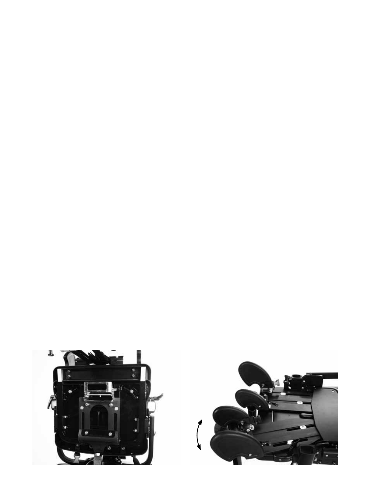
8.14 Sedile — angolazione del supporto
per le anche per le deviazioni “a colpo
di vento”, l’abduzione o l’adduzione
Per regolare l’angolazione dei supporti per le
anche, allentare i dadi (A) sotto ai supporti per
le cosce, impostare l’angolazione desiderata,
quindi serrare saldamente i dadi.
AA
Page 85

8.15 Contenimenti laterali
arti inferiori
8.16 Altezza poggiapiedi
I contenimenti laterali grandi e piccoli per gli
arti inferiori possono anche essere rimossi, o
essere utilizzati in qualsiasi combinazione per
adattarsi alle necessità dell’utente.
Per modificare l’angolazione o la larghezza
dei contenimenti laterali, allentare entrambe le
viti (A), regolare nella posizione desiderata e
serrare nuovamente le viti.
Per modificare l’altezza del poggiapiedi,
allentare la vite (A), regolare nella posizione
desiderata, quindi serrare bene le viti.
A
A
Page 86

8.17 Supporto polpacci
Per modificare l’angolazione del supporto per
polpacci, allentare la vite (A) posizionata sulla
sommità del supporto, muovere il supporto
in avanti o indietro nella posizione desiderata,
quindi serrare nuovamente la vite.
A
Page 87

8.18 Dimensioni
poggiapiedi
Per modificare le dimensioni dei poggiapiedi
al fine di adattarli a diverse misure di
scarpe, allentare le viti (A) posizionate nella
parte anteriore dei poggiapiedi, regolare i
poggiapiedi nella dimensione desiderata e
serrare nuovamente le viti.
Nota: È necessario utilizzare una chiave
da 5 mm.
A
Page 88

8.19 Angolazione poggiapiedi
(solo per poggiapiedi complessi)
Per modificare l’angolazione dei poggiapiedi,
allentare le tre viti (A) presenti su giunto
sferico sotto al poggiapiedi, regolare
l’angolazione e serrare nuovamente le viti.
Nota: È necessario utilizzare una chiave
da 5 mm.
Per ribaltare i poggiapiedi, tirare il perno (B)
dietro ai sandali e ruotarlo di 90°. Premendo
nel punto C, fare scorrere il poggiapiedi in
fuori, e piegare verso l’alto. Il poggiapiedi è
ora bloccato in posizione verticale.
A
B
B
B
C
C
C
C
Page 89

8.20 Braccioli
Per modificare l’altezza dei braccioli,
allentare la manopola (A), regolare all’altezza
desiderata, quindi serrare nuovamente la
manopola.
Per regolare l’angolazione, tirare in fuori
il perno (B) e ruotare il bracciolo fino a
raggiungere la posizione desiderata, quindi
rilasciare il perno, assicurandosi che vada a
inserirsi saldamente in uno dei fori.
Le pelotte per i braccioli possono essere
spostate in avanti o indietro togliendo le viti
(C), riposizionando la pelotta e serrando bene
le viti.
A
B
8.21 Basculamento
L’angolo del basculamento può essere
regolato mentre l’utente è seduto. Prima di
variare tale angolo, assicurarsi sempre che
l’imbragatura pelvica avvolgente “cradle” sia
ben fissata per evitare che l’utente scivoli
sul sedile.
Per regolare il basculamento, impugnare
la maniglia di spinta e inclinare il sedile
spingendo la leva.
Impugnare saldamente le maniglie di spinta
prima di usare la leva di basculamento.
C
Page 90

8.22 Regolazione altezza
della base Hi-low
È possibile effettuare questa regolazione con
l’utente seduto. Se la base presenta il perno
di sicurezza del pedale (A), prima sbloccarlo
estraendo il perno e ruotandolo di 90 gradi.
Per regolare l’altezza della base idraulica
Hi-low spingere la leva (B) dietro alla base col
piede.. Per diminuire l’altezza, appoggiare il
piede sotto al pedale e sollevarlo, l’altezza del
sedile si abbasserà gradualmente.
Per sicurezza, inserire sempre il perno
estraibile dopo aver effettuato la
regolazione.
Per regolare l’altezza della base elettrica,
utilizzare i tasti del telecomando. Prima
di utilizzare il prodotto per la prima volta,
si consiglia di ricaricare completamente
la batteria per 12 ore. Per farlo, collegare
l’adattatore alla presa, collegare il cavo alla
batteria e accendere l’alimentazione di rete.
Una volta ricaricata, spegnere l’alimentazione
di rete, staccare la spina dell’adattatore e
scollegare il cavo dalla batteria. La batteria
dovrebbe essere ricaricata ogni giorno finché
non si illumina la luce verde sul caricabatteria.
È possibile regolare la sedia mentre è
collegata alla corrente.
Assicurarsi che il prodotto e l’utente siano
lontani dai mobili circostanti quando
si regola l’altezza per evitare eventuali
collisioni o danni al prodotto.
A
B
Page 91

9 Informazioni sulla pulizia
e sulla manutenzione
Manutenzione
Quando si pulisce il prodotto, si consiglia di
utilizzare solo acqua calda e detergenti non
abrasivi. Non usare mai solventi organici o
liquidi per la pulizia a secco.
Imbottiture e tessuti
1. Le imbottiture e i tessuti possono
essere lavati in lavatrice e asciugati
nell’asciugabiancheria selezionando
l’impostazione per capi delicati.
I rivestimenti standard possono essere lavati
a 40° C, mentre i rivestimenti anti-infezioni
a 90° C. Si prega di rimuovere la schiuma
prima di lavare i seguenti rivestimenti:
Supporto per le spalle
Supporto toracico
Supporto sacrale
Supporto sacrale anatomico
Sedile
Tutti gli altri rivestimenti morbidi possono
essere lavati direttamente in lavatrice.
Utilizzare una sacca per evitare che i
rivestimenti si rovinino durante il lavaggio in
lavatrice.
2. Per una prima pulizia, strofinare il
rivestimento con un panno.
3. È consigliato rimuovere le macchie il
prima possibile con un panno assorbente,
un asciugamano o una spugna. La pulizia
ordinaria con una spugna impregnata di
acqua e sapone è sufficiente per lo sporco
ordinario e per piccole macchie. Fare
attenzione a non bagnare eccessivamente il
tessuto, altrimenti le macchie tenderanno ad
allargarsi.
4. Assicurarsi sempre che il prodotto sia
asciutto prima dell’uso.
Componenti in metallo e plastica
1. Per la pulizia quotidiana è possibile
utilizzare acqua e sapone o spray battericidi.
2. Per una pulizia più profonda, si può
utilizzare un pulitore a vapore a bassa
pressione.
3. Non usare solventi per pulire componenti
in plastica, legno o metallo.
4. Assicurarsi che il prodotto sia asciutto
prima dell’uso.
Page 92

10 Controllo quotidiano
del prodotto
(Terapisti, genitori e assistenti)
Si consiglia a terapisti, genitori o assistenti
di effettuare controlli quotidiani del sistema,
per assicurarsi dell’uso sicuro dello stesso. I
controlli consigliati sono:
Controlli sedile
1. Tutti i bulloni e le manopole atti alla
regolazione devono essere in sede e saldi.
2. Verificare che non ci siano segni d’usura
nelle imbottiture.
3. Controllare tutte le strisce in velcro ed
eliminare la lanugine per assicurarsi che le
cinture si chiudano saldamente.
4. Controllare che tutti i supporti posteriori
siano ben fissati.
Controlli base
1. Controllare che tutte le ruote si muovano
liberamente e che possano essere bloccate
in sicurezza.
2. Controllare che il meccanismo di
regolazione dell’altezza della base funzioni e
che il pedale sia bloccato.
3. Controllare che il basculamento funzioni e
che si blocchi in posizione in sicurezza.
4. Controllare che il perno di bloccaggio sulla
maniglia di interfaccia sia ben bloccato in
posizione.
In caso di dubbi sulla persistenza dell’uso
sicuro del vostro prodotto Leckey o
nel caso in cui alcune parti dovessero
rompersi, si prega di non utilizzare il
sistema e contattare il nostro customer
service o il vostro rivenditore locale il
prima possibile.
11 Controllo annuale del
prodotto
(Terapista, tecnico, product advisor
Leckey, rivenditore)
Leckey raccomanda il controllo dettagliato
del prodotto almeno una volta all’anno.
Tale controllo dovrebbe essere effettuato
da personale tecnico competente,
formato sull’uso del prodotto, e dovrebbe
comprendere i seguenti punti come requisito
minimo.
1. Controllare le manopole, bulloni, dadi
e fibbie di plastica, sostituendo le parti
mancanti, prestando particolare attenzione a:
- fibbie e velcro sull’imbragatura pelvica
- la maniglia del sedile si blocca e si sblocca
correttamente
- il basculamento e la regolazione dell’altezza
vengono eseguiti in sicurezza e possono
essere bloccati in sicurezza
- tutti i giunti sferici bloccano in sicurezza i
supporti per spalle, torace, anche e piedi
- è possibile regolare e bloccare in sicurezza
l’angolazione dello schienale
- è possibile regolare e bloccare in sicurezza
l’angolazione dei supporti per le gambe
- è possibile regolare e bloccare in sicurezza
l’altezza e l’angolazione dei braccioli
- è possibile bloccare in sicurezza il
poggiatesta
2. Sollevare la base per controllare ogni
singola ruota. Controllare che le ruote si
muovano liberamente e rimuovere lo sporco
dalle ruote in gomma. Controllare che i freni
blocchino le ruote in sicurezza.
Page 93

3. Controllare la struttura del prodotto,
prestando attenzione ai punti di saldatura sul
telaio, assicurandosi che non ci siano segni
di rottura intorno ai punti di saldatura.
4. Leckey consiglia di conservare
documentazione scritta relativa a tutti i
controlli annuali sul prodotto.
In caso di dubbi relativi sulla persistenza
dell’uso sicuro del vostro prodotto Leckey
o nel caso in cui alcune parti dovessero
rompersi, si prega di interrompere
l’uso del prodotto e contattare il nostro
customer service o il vostro rivenditore
locale il prima possibile.
12 Ridistribuzione dei
prodotti Leckey
La maggior parte dei prodotti Leckey
vengono valutati e ordinati per soddisfare
i bisogni del singolo utente. Prima di
riassegnare un prodotto, consigliamo che il
terapista e medico prescrittori effettuino un
controllo della compatibilità delle attrezzature
per il nuovo utente e che si assicuri che il
prodotto riassegnato non presenti modifiche
o accessori speciali.
Sarebbe opportuno effettuare un controllo
tecnico dettagliato sul prodotto prima di
riassegnarlo.
Tale controllo dovrebbe essere effettuato
da personale tecnico competente, formato
sull’uso e al controllo del prodotto. Si prega
di fare riferimento alla sezione 11 per i
controlli necessari.
Assicurarsi che il prodotto sia stato pulito
accuratamente in conformità con la sezione
9 del presente manuale.
Assicurarsi che una copia del manuale d’uso
venga fornita assieme al prodotto. Una copia
può essere scaricata dal nostro sito www.
leckey.com.
Leckey consiglia di conservare
documentazione scritta relativa a tutti i
controlli effettuati sul prodotto durante la sua
riassegnazione.
In caso di dubbi relativi sulla persistenza
dell’uso sicuro del vostro prodotto Leckey
o nel caso in cui alcune parti dovessero
rompersi, si prega di interrompere
l’uso del prodotto e contattare il nostro
customer service o il vostro rivenditore
locale il prima possibile.
Page 94

13 Assistenza prodotto
L’assistenza su tutti i prodotti Leckey
dovrebbe essere effettuata unicamente da
personale tecnico competente, formato
sull’uso del prodotto.
Tutte le richieste di assistenza internazionali
dovrebbero essere rivolte all’apposito
distributore Leckey che sarà lieto di
aiutarvi. Per ulteriori informazioni sui
distributori Leckey visitate il nostro sito
www.leckey.com.
14 Informazioni
tecniche
Codici dei prodotti e degli accessori
133-1600-FIX Unità sedile con asse dello
schienale fisso formato 1
133-1600-REM Unità sedile con asse dello
schienale rimovibile formato 1
139-2600-FIX Unità sedile con asse dello
schienale fisso formato 2
139-2600-REM Unità sedile con asse dello
schienale rimovibile formato 2
133-404* Imbottitura e rivestimento
sedile in schiuma alveolata
formato 1
139-404* Imbottitura e rivestimento
sedile in schiuma alveolata
formato 2
133-405* Imbottitura e rivestimento
sedile in memory foam
formato 1
139-405* Imbottitura e rivestimento
sedile in memory foam
formato 2
133-611 Unità supporto spalle
formato 1
139-611 Unità supporto spalle
formato 2
133-400* Imbottitura e rivestimento
supporto spalle formato 1
139-400* Imbottitura e rivestimento
supporto spalle formato 2
133-605 Unità supporto toracico
133-401* Imbottitura e rivestimento
supporto toracico
133-619 Componenti supporti toracici
laterali con inclinazione
regolabile
133-402* Imbottitura e rivestimento
toracici con inclinazione
regolabile
133-612* Unità supporto sacrale
133-403* Imbottitura e rivestimento
supporto sacrale
133-604 Supporto sacrale anatomico
formato 1
133-400* Imbottitura e rivestimento
supporto sacrale anatomico
formato 1
+10 azzurro
+11 grigio +12 viola
+13 grigio (controllo di infezione)
Page 95

Base
133-750 Kit base Hi-low – idraulica
133-760 Kit base Hi-low – elettrica
133-770 Base per la mobilità Leckey
133-740 45cm Base e interfaccia per la
mobilità Discovery
Opzioni interfaccia per la mobilità
139-726 Interfaccia Discovery A
da 45mm
Accessori
133-728 Cinghia Pelvica formato 0
133-729 Cinghia Pelvica formato 1
133-730 Cinghia Pelvica formato 2
133-731 Cinghia Pelvica formato 3
133-608 Pelotte laterali per le anche
(coppia)
133-737 Supporto glutei Cinghia Pelvica
133-609 Supporti laterali ribaltabili
(singolo pezzo, senza
rivestimento)
133-747 Rivestimenti laterali
(singolo pezzo)
133-622-LH Supporti laterali ribaltabili –
orizzontali, sinistra (singolo
pezzo, senza rivestimento)
133-622-RH Supporti laterali ribaltabili –
orizzontali, destro (singolo
pezzo, senza rivestimento)
133-614-LH Supporti laterali complessi
ribaltabili – verticali, sinistra
(pezzo singolo con rivestimenti)
133-614-RH Supporti laterali complessi
ribaltabili – verticali, destro
(pezzo singolo con rivestimenti)
133-625 Supporto sternale
133-1626 Pelotta sternale formato 1
133-2626 Pelotta sternale formato 2
133-3626 Pelotta sternale formato 3
133-627 Poggiatesta anatomico
regolabile
133-716 Rivestimento poggiatesta
anatomico regolabile
133-626 Poggiatesta anatomico in PU
133-735 Braccioli (coppia)
133-635 Tavolino – chiaro
133-624 Tavolino – nero
133-680 Inserto tavolino imbottito
133-721 Cinghie per le gambe (coppia)
133-601 Pacco contenimenti laterali
per gli arti inferiori
(2 grandi e 2 piccoli)
133-682 Contenimenti laterali arti
inferiori grandi – destra
133-686 Contenimenti laterali arti
inferiori grandi – sinistra
133-683 Contenimenti laterali arti
inferiori piccoli – destra
133-687 Contenimenti laterali arti
inferiori piccoli – sinistra
133-1005 Pacco distanziatori in schiuma
(per l’inclinazione)
133-606 Poggiapiedi – giunti sferici
(coppia)
133-607 Poggiapiedi – versione base
(coppia)
133-712 Cinghie sandali formato 1
133-742 Cinghie sandali formato 2
133-765 Rivestimento imbottito lungo
l’asse longitudinale (set)
133-726 Rivestimenti elemento di
protezione supporto laterale /
staffa (pezzo singolo)
133-749 Staffa Whitmyer
133-745 Staffa poggiatesta per sezione
quadrata da 1/2” e 15 mm
WASH01 Custodia per lavatrice
Page 96

Dimensioni del sedile KIT
Misure prodotto Misura 1 Misura 2
mm mm
Fascia d’età 12-18 anni dai 16 anni in su
Altezza
Min 1400 1600
Max 1650 1850
Peso max utente (kg/libbre) 75 75
Profondità sedile
Min 360 410
Max 480 560
Correzione max deviazione “a colpo di vento” 20° 20°
Larghezza max sedile – senza supporti laterali 430 430
Larghezza sedile – con supporti per le anche
Min 215 215
Max 370 370
Altezza schienale
Min 500 560
Max 620 675
Larghezza spalle
Min 190 260
Max 500 600
Larghezza torace
Min 230 230
Max 380 380
Angolo di inclinazione schienale 90°-120° 90°-120°
Distanza sedile – poggiapiedi
Min 330 330
Max 510 510
Altezza braccioli
Min 165 190
Max 263 290
Dimensioni tavolino 630 x 460 630 x 460
Peso sedile (sedile e schienale) 20.5 kg 21 kg
Page 97

Opzioni base Hi-low Leckey
Specifiche attuatore LINAK – 281209-01
Grado di protezione IP51
Ciclo funzionamento Max 10% o 2 min uso
continuo seguito da 18 min di riposo.
T ambiente da +5° a 40°C
T ambiente di funzionamento 22°C
T di deposito da -40°C a 70°C
Forza max in spinta 3500 N
Forza max in tiro 2000 N
Bloccaggio automatico con spinta 3500 N –
tiro 2000 N
Velocità tipica a pieno carico 4,7 mm/sec
Ampere max con carico di 3500 N: 3,9 A
Livello di rumorosità dB(A) 48
Tensione potenza in ingresso 24 v +-10%
Cassetta batterie LINAK – BA18021-00
Grado di protezione IP51
T ambiente da +5° a 40°C
T di deposito da -20°C a 60°C
Potenza nominale 1,2 Ah 24v
Corrente di carica pari a max o,3°
Batteria piombo-acido/gel
Maniglie LINAK – HB41000-00004
Grado di protezione IP51
Corrente di comando 100mA per canale
(max)
T ambiente da +5° a +40°C
Caricabatterie LINAK – CH01
Alimentazione 100-240 VAC/50-60Hz
alimentatore a commutazione
Tensione di carica 27,6 VDC +-2%
Corrente di carica max 500mA
LED verde di accensione
LED giallo per la funzione di ricarica
Il LED giallo diventa verde quando le batterie
sono state completamente ricaricate.
I prodotti LINAK possono essere conservati
in depositi non riscaldati con un tasso di
umidità compreso tra lo 0 e il 100%, non
condensante. “Non condensante” implica
che non si dovrebbe prendere un prodotto
da un magazzino ghiacciato a una stanza
con una temperatura di 20°C; in caso
contrario si creerà una patina di umidità
sui prodotti.
Base Hi-low KIT
mm
Distanza parte superiore sedile – pavimento
Min 460
Max 640
Con le maniglie piegate
Lunghezza 700
Larghezza 620
Altezza 410
Page 98

Page 99

Page 100

1. Verwendungszweck
Das KIT-Sitzsystem ist eine Sitzschale,
die für Erwachsene und Jugendliche
(ab dem 12. Lebensjahr) mit
Behinderungen entwickelt wurde, und die,
falls auf einem fahrbarem Untergestell,
zu Hause, in Tageszentren, in Schulen
und im Freien verwendet werden kann.
Das maximale Benutzergewicht des
Sitzsystems liegt bei 75 kg. Es ist modular
und kann mit einem Fahrgestell verwendet
werden, welches für den Innen- oder
Außenbereich geeignet ist. Das Hi-LowFahrgestell wurde für den Innenbereich
entworfen, kann jedoch auch außen
auf ebenen Flächen verwendet werden.
Die Elemente am Hi-Low-Fahrgestell
sollte nie freigelegt werden, da dies die
Metallkomponenten beschädigen könnte.
Die KIT-Sitzschaleneinheit lässt sich mit
vielen fahrbaren Untergestellen verbinden.
Die Einzelheiten darüber finden Sie auf
unserer Webseite: www.leckey.com.
2. Konformitätserklärung
James Leckey Design Ltd. erklärt als
Hersteller in alleiniger Verantwortung, dass
das KIT-Sitzsystem den Anforderungen
der Richtlinien 93/42/EWG, den
medizinproduktrechtlichen Vorschriften
2002 und EN 12182 “Technische Hilfen für
Personen mit Behinderungen – Allgemeine
Anforderungen und Prüfverfahren”
entspricht.
3. Garantiebedingungen
Der Hersteller haftet nur, wenn das
Produkt unter den vorgegebenen
Bedingungen und zu den vorgegebenen
Zwecken eingesetzt wird, wobei
allen Empfehlungen des Herstellers
Folge geleistet wird (siehe auch
allgemeine Geschäfts-, Lieferungs- und
Zahlungsbedingungen). Alle von Leckey
hergestellten Produkte und Bauteile
unterliegen einer Garantie von zwei
Jahren.
4. Produkthistorie
Ihr Leckey-Produkt ist ein als Klasse
1 eingestuftes Medizinprodukt, und
sollte als solches einzig von einer
Fachkraft verschrieben, aufgebaut oder
wiedereingesetzt werden, die technisch
kompetent ist, und für den Gebrauch
dieses Produkts geschult wurde. Leckey
empfiehlt alle Einzelheiten des Aufbaus,
Prüfungen für den Wiedereinsatz und
jährlichen Produktinspektionen schriftlich
festzuhalten.
5. Aufzeichnung der Produktschulung
(Eltern, Lehrer und Betreuer)
Ihr Leckey Produkt ist ein verordnetes
Medizinprodukt der Klasse 1 und als
solches empfiehlt Leckey auch, dass die
Eltern, Lehrer und Betreuer, die dieses
Gerät verwenden, über die folgenden
Abschnitte dieser Anleitung unterrichtet
werden müssen:
Abschnitt 6
Sicherheitsinformationen
Abschnitt 8
Klinischer Aufbau zur Haltungskontrolle
Abschnitt 9
Reinigung und Pflege
Abschnitt 10
Tägliche Produktüberprüfung
Leckey empfiehlt, dass eine schriftliche
Aufzeichnung von allen Personen gemacht
wird, die für den ordnungsgemäßen
Gebrauch dieses Produkts ausgebildet
wurden.
 Loading...