

Page 1
15-124 Białystok ul. Gen. Andersa 5D/4
tel. (085) 675 45 03; fax. (085) 675 52 34
www.lecholpg.pl
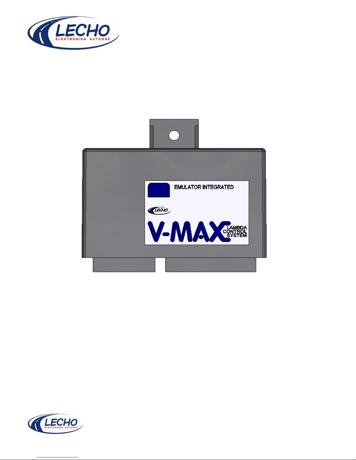
V-Max
DESCRIPTION OF CONTROLLER TUNING
WITH V-MAX COMPUTER PROGRAM
Page 2

Table of contents:
1.Introduction.
2.Technical data
3.Controller connection
4.Lead functions description
5.V-MAX program description
6.Controller programming
7.Advanced parameters
8.Clip connection
9.Set contents
10.Contact
Page 3
Service and tuning manual of V-Max controller
1. Introduction
We have the pleasure to invite you to familiarize yourself with our product presented in this
instruction manual.
LECHO Elektronika autogaz company has done its best to deliver you the highest quality
product. Our products undergo a careful selection at all manufacturing stages. Using the newest
technologies allows us to achieve expected effects, while considerably reducing costs of worked out
solutions. That is why, our products are and will stay competitive in prices in relation to other products
of the same class that are available on the market.
2. Technical data:
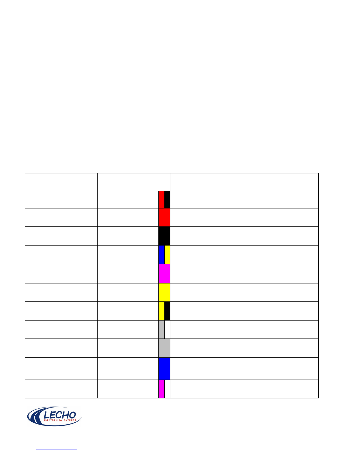
V-Max controller has inputs that are connected directly to the already existing car electric system as
well as outputs that are connected to control elements enclosed in the set. Input and output
parameters are presented in the table below:
Tab. 1 – input/output parameters
Input description Wire colour Nominal parameters
Controller supply voltage Red-black U
supp.(1).
= 10 – 16V; I
supp.(1).
=0.8A
Relays supply voltage Red
U
supp.(2).
= 10 – 16V; I
supp.(2).
=3 - 6A (depending on
type and number of used solenoid valves)
Ground Black I
max=Isupp.(1)+Isupp.(2)
=7A
TPS signal input Blue-yellow
U
input
=0 – 15V; I
input
=1..5µA (R
in(max)
=5MΩ)
Lambda probe signal
input
Violet
U
input
=0 – 5V; I
input
=1..3µA (R
in(max)
=5MΩ)
Tank gas level input Yellow
R=(0 – 90) Ω or R=(0 – 20)kΩ
Rotational speed signal
input (1)
Yellow-black
U
input(rect.)
=8 – 30V in relation to mass; R
in
=50kΩ
Unused
Grey - white
Lambda probe
simulation output
Grey U
output
=0 –0.8V; 0 – 1.5V; 0 – 4.5V; R
out
=
solenoid valve +
emulator switching on
gas output
Blue U
output.=Usupp.(2)
-0.5V
Single-point emulator
output
2x violet – white
R
emul.
=100Ω ±5Ω; I
emul.(max)
=0.15A
R
switch.(max)
=0.1Ω; I
switch.(max)
=6A
Page 4
3. Controller connection
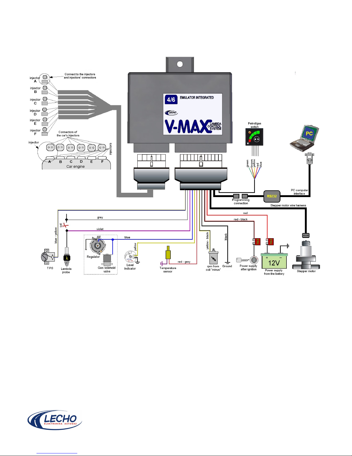
The controller connection to a car system is presented as a diagram on Fig. 1.
All connections should be made reliably with soldered ends. It's forbidden to connect cables “as
twisted pair” since it can lead to incorrect system operation.
czerwono-szary
Page 5

4. Lead functions description
The stepper motor is connected by means of a plug, so it is not necessary to describe wires – an
incorrect connection is not possible.
Red-black wire: connection to power supply after turning the key in the ignition.
Red wire: It's connected to the battery (+).
Blue wire: This is a 12V voltage output that is used for switching on gas solenoid valves. The wire is
live after the V-Max controller is switched to gas drive mode. In no other case the should the wire be
live. Maximum output load is 6A of continuous current. It gives the conversion factor for connected
solenoid valves: 4.
Blue-yellow wire: The wire serves for receiving a signal from the throttling valve position sensor
(TPS). Voltage value on this input can be from 0V to 12V. Thanks to it, the input can be connected to
any TPS type including switches to mass or to power supply. Setting of TPS level in the control
program is the voltage value at low revolutions + 0.05…0.1V. Example of TPS at low revolutions:
0.65V – what gives a minimum setting in the program of: 0.7…0.75V. Setting of lower or equal values
to those at low revolutions does not ensure correct operation of the stepper motor in V-Max.
Violet and grey wires. These are standard connections to the Lambda probe. Cut the Lambda probe
signal wire and connect the violet wire to the probe and the grey wire to the computer. The controller
reads out the signal from the Lambda probe and on its basis selects the gas optimum dose. The
second cable supplies the probe simulation signal to the computer in order to deliver information from
the lambda probe to the computer in the car.
Yellow wire: This is the gas level input in the tank. Always connect it to the reserve indicator installed
on the tank. It is recommended to use additional mass wire to connect reserve indicators. Connect this
wire at the point in which the V-MAX controller is connected to mass. In this way, noise is reduced and
the gas level signaling in the tank is improved.
Yellow-black wire: serves for reading the revolution's signal. It uses the standard signal that controls
the ignition coil, so connect it to the ignition module output (the ignition coil minus).
Black wire is the ground. It must be connected to the BATTERY ground(-).
Violet-white wires (both together in a covering) serve for cutting off the injector with single-point
injection operation. Resistance when contacts are opened is 100R what should be enough for most
cars. The cutting off time is controlled by the program. The parameter is named: “P/G switching
time”. These wires should be connected to the injector, previously cutting the injector signal wire.
Order of the wires doesn't matter.
Separate red-grey wire serves for connecting the temperature sensor. The wire cooperates only with
the sensor supplied in the set with the controller. The sensor polarization is of no meaning – colors
that are lead from the sensor can be also different in various makings. To connect the sensor correctly,
connect any of the wires to mass and the other wire to the controller input.
Page 6
5. V-MAX program description
Program requirements:
Windows 98/Me/XP operating system
Hard disk free space: 2MB
NOTE. The program runs correctly also with USB-COM adapters. Depending on the operating system,
problems with communication may occur when using such an adapter. We reccomend using Windows
XP.
Amount of RAM used by the program: 30MB
A free COM port (RS-232C) or a free USB port.
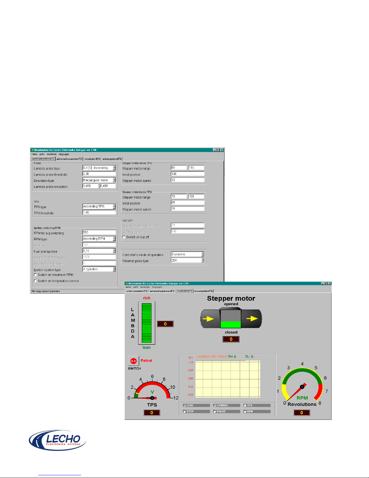
In order to change the controller's parameters a PC computer and a V-MAX software (ver. 0.9 or
higher) is required. AFTER connecting the controller click COM port settings and then AUTODETECT.
The program will detect to which port the controller is connected, and will display a message on the
status bar. After a proper connection is established you can proceed to programming the controller.
Page 7
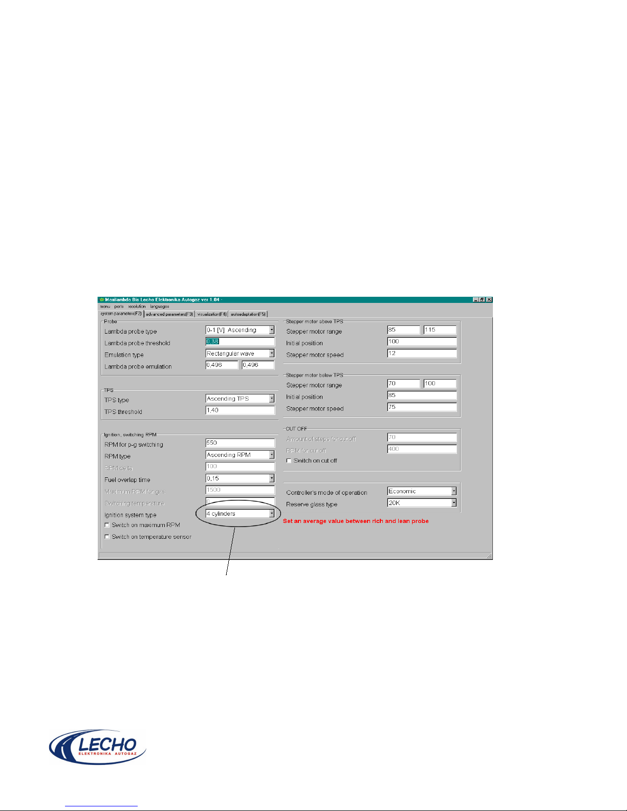
Navigation: the program is based on a tab system. You can navigate between the tabs by clicking on
them, or pressing a proper key (indicated at the tab's name).
Changing a parameter in any of the editing windows is applied in the controller immediately. There's
no need to save it.
After choosing an editing window every parameter is explained with a separate description in the lower
right corner. It applies both to basic and advanced parameters.
Any incorrect value of a parameter is not accepted by the program. Depending on the parameter type
it is either ignored or changed into standard value.
6. Controller programming
After the interface is connected to the controller, the system programming can start.
Make selection with arrow keys or by clicking the selection beam
After selecting the inginition system type correctly, you may proceed to setting the controller's
parameters.
Basic parameters such as the lambda probe type and TPS should be set before the controller is
switched to the gas operation mode. That is why the next step is to start the window with a preview of
the lambda probe, TPS, revolutions and level of the stepper motor opening. In order to do that, click
“Visualization” in the main window or press F4 key.
Page 8
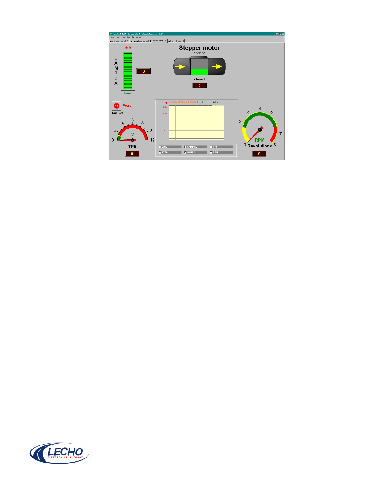
A new window opens:
car parameters preview window.
Observe and remember voltage on TPS sensor at low revolutions run in the visualization window.
Notice the limits (a chart or a bar) within which the lambda probe voltage changes.
TPS standard operating conditions are 0 – 5V, 5 – 0V, 0 – 12 V, 12 – 0 V SWITCH, 0-2,5V, 2,5V-0.
Standard lambda probe types are 0 – 1V, 0 – 5V or 5 – 0V (the probe operates in reverse direction).
6a. tuning:
1. Select LAMBDA PROBE TYPE from the standard probe types (0..1V; 0,8..1,6V; 0..5V; 5..0V), set
the type according to information from the VISUALIZATION window.
2. The next parameter is LAMBDA PROBE THRESHOLD. Here, select as a standard ½ from the
probe range, that is for a 0..1V probe, the threshold is 0.5V for 0..5V probe it is 2.5V, for a 0.8..1.6V
probe it is 1.2V. Such a threshold level should be set only for a new probe, the upper voltage of which
(with rich mixtures) is 1V or slightly less. For probes that are used up and their maximum voltage does
not reach the upper value (1V, 1.6V or 5V) set a lower threshold. The value should be half of the
lambda probe maximum indicated voltage, that is, for the probe operating within the range: 0..0.8 V
the correct switching threshold equal to 0.4V should be set. This ensures that the stepper motor
changes direction of revolutions exactly at the moment of the fuel mixture change at a ratio of 14.7:1.
The parameter changes within the range: 0..5V with a resolution of 0.02V.
3. The next parameter is PETROL / GAS RPM THRESHOLD. Although this parameter can be set
freely according to your wish, the recommended value is from 1800 to 2500 rpm. This parameter
shows at what level of engine revolutions, the car feed is switched from petrol to gas. The parameter
changes within the range: 300..9950 rpm with a resolution of 100 rpm.
4. The next parameter is TPS TYPE. It defines the direction of the throttling valve position sensor
values in relation to the engine speed. In case of low voltage value at low revolutions and higher one
Page 9

when revolutions are increased, select ASCENDING and in a reverse situation, select DESCENDING.
The parameter changes within the range: select from the list.
5.The next parameter is TPS THRESHOLD. In this parameter, set voltage threshold from TPS sensor
at which the stepper motor is rapidly opened to the maximum value. This is operation during changing
from low revolutions to operating revolutions. Thus, the value should be slightly higher than the TPS
voltage level at low revolutions. At TPS voltage at low revolutions equal to 0.75V, set a threshold equal
to 0.8V at least. The TPS input hysteresis is 0.025V what will cause switching at voltage increase at a
value of 0.825V and at voltage drop: at 0.775V value. Due to noise existence in the supply leads and
due to errors resulting from TPS sensor construction, we recommend setting a value higher by 0.1V at
least, in relation to the values at low revolutions. The parameter changes within the range: 0..12V with
a resolution of 0.05V.
6. RPM TYPE. This parameter defines the moment at which the feed is switched from petrol to gas. In
case ASCENDING values are selected, switching to gas will take place at the moment the set P/G
revolutions are exceeded. In case DESCENDING values are selected, switching to gas will take place
when revolutions are reduced by set value. When the DESCENDING option is selected the below
additional parameter will be activated:
6a. RPM DELTA. This parameter defines how much should the revolutions decrease from the
maximum value in order to switch to gas supply.
In both cases it is required to exceed the limit set for the parameter PETROL / GAS RPM
THRESHOLD, that is, at the set value of 2000 rpm and DESCENDING option selected, in order to
switch to gas, revolutions should be increased above 2000 rpm. Value above 2000 rpm is not
important. Switching will take place at the moment the revolutions decrease from the maximum value
by the value set for the parameter RPM DELTA.
NOTE. RPM delta is a parameter that changes dynamically and its value corresponds to the P/G
switching threshold, that is, at a threshold equal to 2000 rpm and delta equal to 1000 rpm, during
increase of revolutions up to 3000 rpm and releasing the accelerator – switching will take place at a
value equal to 2000 rpm whereas, during increase of revolution up to 6000 rpm and releasing the
accelerator – switching will take place at the revolutions value equal to 3000 rpm. The real value of
revolution decrease is:
RPM delta x reached number of revolutions / P/G RPM threshold
It gives equal time to the switching moment when higher revolutions are reached.
Parameter recommended values: 500..1000 rpm. Range of the parameter changes: 0..5000 rpm with
a resolution of 100 rpm.
7. STEPPER MOTOR RANGE ABOVE TPS. This parameter defines the range within which the
stepper motor's piston moves. Set the initial values equal to 10 and 240, then exit the parameters'
change window, enter the visualization window and observe within what range (on gas) the stepper
motor moves on high revolutions (2500-3000 rpm). In order to set the MINIMUM value (left window)
take the bottom range of the stepper motor on high revolutions and subtract 15 steps. In order to set
the MAXIMUM value take the top range of the stepper motor on high revolutions and add 15 steps.
That is, if the stepper motor operates on high revolutions within the range 90..110, then set 125 steps
in the maximum window (right window), 75 steps in the minimum window (left window) and 100 steps
in the initial position window (bottom window). The parameter range of change: 0..255 steps, where
0=closed flow, 255=maximum flow.
Page 10

8. STEPPER MOTOR RANGE BELOW TPS. This parameter defines the range within which the
stepper motor's piston moves on idle gear. Set the initial values equal to 10 and 240, then exit the
parameters' change window, enter the visualization window and observe within what range (on gas)
the stepper motor moves with the accelerator released. In order to set the MINIMUM value (left
window) take the bottom range of the stepper motor on low revolutions and subtract 15 steps. In order
to set the MAXIMUM value take the top range of the stepper motor on low revolutions and add 15
steps.
That is, if the stepper motor operates on low revolutions within the range 60..70, then set 85 steps in
the maximum window (right window), 45 steps in the minimum window (left window) and 65 steps in
the initial position window (bottom window). The parameter range of change: 0..255 steps, where
0=closed flow, 255=maximum flow.
9. LAMBDA PROBE TIMES. These parameters set the shape and period of the signal that simulates
the lambda probe for the computer in the car. Simulation times should correspond to real readouts of
the lambda probe during drive on petrol feed. Due to fast petrol mixture ratio regulation, it is virtually
impossible to readout the lambda probe times for petrol run. That is why, feed should be switched to
gas before checking the lambda probe response times (VISUALIZATION window and oscilloscope
with LAMBDA run switched on). It is assumed that the probe response time on gas is twice longer
than during petrol operation. That is why, the readout times of rich and lean mixtures at average
revolutions (approx. 2000 rpm) should be shortened by half and such values entered for LAMBDA
PROBE TIMES parameters. Enter the values correspondingly: in the left window – rich mixture time
(TH – Time High), in the right window – lean mixture time (TL – Time Low). Enter the values in
milliseconds (1 ms = 0.001 s). The range of entered values is from 0 to 4000 ms. Maximum value of
TH+TL sum is 8000 ms. For an ideal system, TH and TL should be equal.
The controller allows to switch off simulation completely. In order to do that, mark the box: BOSCH
TYPE SIMULATION or enter 0 ms values in TH and TL. On the simulation output, mass appears then.
NOTE. Incorrect selection of TH and TL values will lead to error indication by switching on of the
CHECK indicator in the car. In such case correct values untill the CHECK indicator switches off.
10. CUTOFF SWITCHING ON. This parameter defines the cutoff function - partial gas feed cut off
during braking with the engine. This function is used in cars with an automatic gearbox and in newer
cars equipped with a manual gearbox in which computer disconnects petrol injectors during braking.
When switched on, the below additional parameters appear:
10a. STEPPER MOTOR AT CUTOFF. This is a parameter that defines the stepper motor value level
to which it will be set when the accelerator is released during drive. This value should be within the
stepper motor operation range (between min. and max. values). To throttle the engine, set a value that
is close to the stepper motor's minimum. The range of changes is from 0 to 255 steps. Recommended
value is: the stepper motor minimum + 5 steps.
10b. RPM FOR CUTOFF. This parameter defines the car's engine revolutions level down to which the
CUTOFF function will operate. During decrease of revolutions and the CUTOFF function switched on,
the stepper motor stays at the set value untill the speed drops below the number of revolutions set for
this parameter. The parameter's value must not be set lower or equal to low revolutions since this will
lead to engine stall or to lack of the mixture adjustment at low revolutions. Set a value at a level by at
least 500..1000 revolutions higher than the value of low revolutions. The parameter range of change is
300..9950 rpm with a resolution of 100 rpm.
Page 11

11. STEPPER MOTOR OPENING. This parameter defines the value of the stepper motor's additional
opening during operation above TPS threshold. It gives a possibility of a slight gas dose increase
during normal drive. This value should be from 2 to 10 steps – at a higher value a gas overflow may
take place. The function checks TPS voltage value and if within 0.5s the TPS voltage increase is
higher than 20% of temporary value, additional stepper motor opening takes place with maximum
speed (independently on the stepper motor's set speed above TPS). This parameter also prevents
temporary mixture weakening thanks to which gas backfire is prevented. In cars with a collector made
of plastics, set the parameter within the range from 5 to 12 steps, depending on the engine's cubic
capacity (the bigger the cubic capacity the higher the parameter value). The parameter range of
change is: 2..50 steps.
12. MODE OF OPERATION. This parameter defines the stepper motor's character of operation at the
moment of change from slow revolutions to operating revolutions. When the ECONOMIC option is
selected, after exceeding the TPS threshold, the stepper motor opens with a speed equal 1 to the
initial position above TPS, and then the lambda probe signal starts controlling it. In case the
ECONOMIC+MAX OPENING option is selected, after exceeding TPS threshold, the stepper motor
opens with a speed equal 1 to the maximum position above TPS, then returns to the initial position
above TPS and then the lambda probe signal starts controlling it. When the DYNAMIC option is
selected, after exceeding TPS threshold, the stepper motor opens with a speed equal 1 to the
maximum value above TPS, then the lambda probe signal starts controlling it. Setting the operation
mode type depends on the motor type - select experimentally one of the options at which the car
engine will operate optimally.
13. RESERVE GLASS TYPE. This parameter defines the type of gas level sensor that is installed on
the multi-valve. Possible sensor types are: 0..90Ω (BRC multi-valves), 0..20kΩ (LOVATO,
TOMASETTO, OMVL multi-valves). For a normal reserve sensor without full indication – select the
0..90Ω option.
Page 12
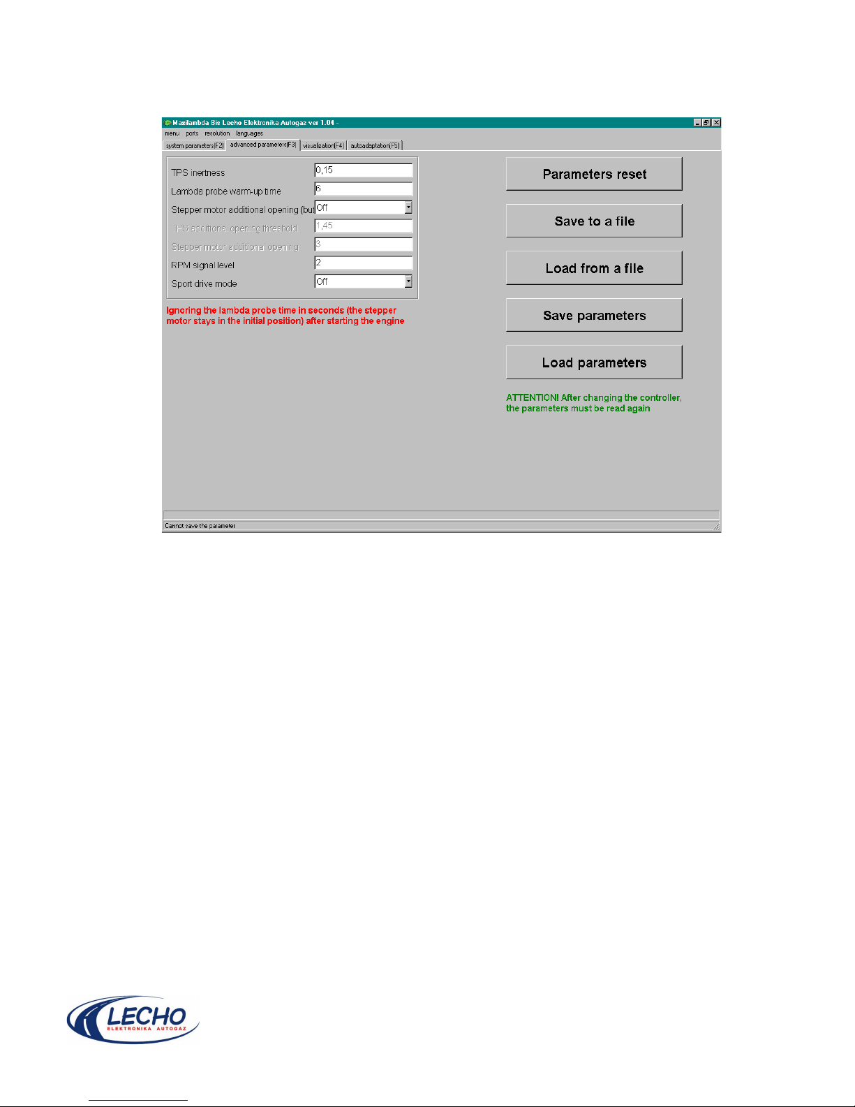
7. Advanced parameters
Advanced parameters window
1. TPS inertness is the tolerance for TPS value change. When this tolerance is exceeded, the
stepper motor's position will change.
2. Lambda probe warm-up time (in seconds). Time, during which the controller ignores the signal
coming from the lambda probe.
3. Stepper motor additional opening may be set in two ways: switched on, if we want to apply an
extra gas dose during rapid acceleration, or off.
4. TPS additional opening threshold is an absolute value (in Volts), exceeding which causes an
additional opening of the stepper motor. (The previous parameter must be set in “on” position at the
same time).
5. Stepper motor additional opening defines by how many steps the stepper motor's opening will
increase during rapid acceleration.
6. RPM signal level may also be described as value of suppresing the revolutions's signal
interference. It may be set within the range from 0 to 255. Increase it untill achieving a revolutions
signal free from interference.
7. Sport drive mode. When switched on, it enables delivering a larger gas dose. It causes the
engines' power increase but also a higher fuel consumption.
Page 13
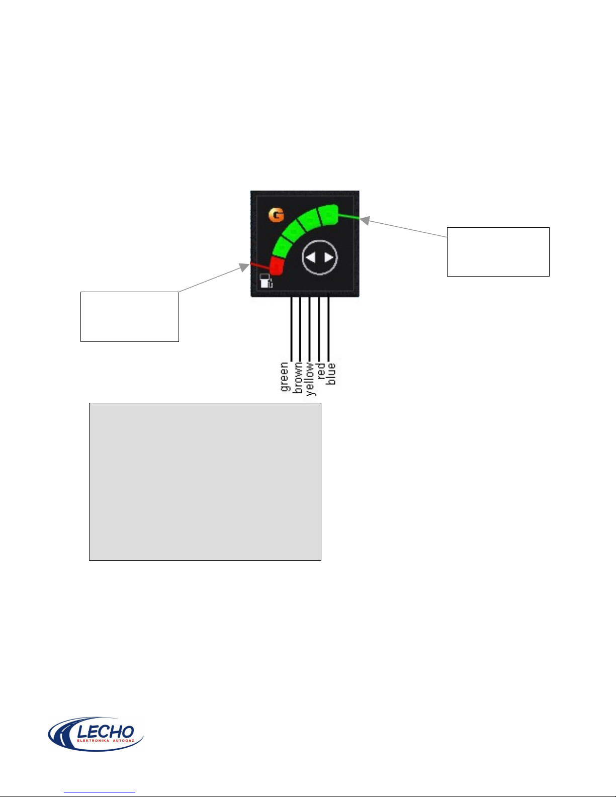
8. Clip (switch) connection
Operation mode indication:
Petrol: diodes in the switch do not light
Automatic operation: R or G1 to G4 diodes flash (depending on gas level in the tank).
Gas: R or G1 to G4 diodes are on continuously (depending on gas level in the tank).
Reserve indication: (operates during operation on gas) diode marked R, is on continuously.
Note. Continuous indication of the gas level operates with the resistance sensor that is installed on
the multi- valve.
Switch (clip) connection diagram
Reserve
indication (R) -
red
Gas indication
(G1...G4) - green
Wires connection:
Switch Switch box
1 Green Green
2 Brown Black
3 Yellow Yellow
4 Red Red
5 Blue Blue
 Loading...