

Lear Seigler ADM-1 Reference Manual
I
I
I
I
I
I
I
I
I
I
I
I
I
I
I
I
I
REFERENCE
CRT
DATA
ELECTRONIC INSTRUMENTATION DIVISION
DISPLAY
Dr.
B.
LEAR SIEGLER, INC.
DATA
MANUAL
ADM-1
by
C.
Edmondson
PRODUCTS
TERMINAL
I
I
NORTH BROOKHURST STREET
714
ANAHEIM,
CALIFORNIA
92803

PREFACE
This reference manual
Terminal. Included
and diagrams, description
is
published
are
specifications, theory
of
CRT, monitor, keyboard, main logic board and power
as
an
aid
to
users
of
the
of
operations, operational logic description
supply, and a section on trouble shooting or failure analysis.
ADM-l,
complete parts lists
and
schematic drawings
are
included in the Appendix.
ADM-l
CRT Data Display
Options available
with
the

TABLE
OF
CONTENTS
Section
Page
I.
ADM-1 SPECIFICATIONS
1-1
II.
THEORY OF OPERATIONS
11-1
CRT Display with
TV
Monitor
11-1
Keyboard
11-3
III.
LOGIC DESCRIPTION
111-1
IV.
TV
MONITOR IV-1
V. INSTALLATION, MAINTENANCE AND
FAILURE ANALYSIS
V-1
Appendix A FACTORY SUPPLIED OPTIONS
Appendix
El
PARTS LISTS
Appendix C
SCHEMATIC DRAWINGS
iii
LIST OF TABLES
Number
.1
1.1
1.2
1.3
1.4
11.1
11.2
11.3
11.4
11.5
11.6
11.7
11:8
11.9
11.10
V:l
IV.2
V.l
V.2
V.3
ADM-l
ADM-l
ADM-l
Absolute Cursor Positionery
ADM-l
Table
Table
Random
ROM
Table
RAM Address
Table
Asynchronous Receiver (Transmitter Control)
Tri
ADM-l
Monitor
CRT Display Specifications
I nterface Connector Signal/Pin List
Failure Analysis Guide
Main Logic Board
Specifications
Keyboard Operations
Binary Code
ESC
Sequences
of
Register
of
Condition
Access
Instruction Execution Sequence Control
of
Conditions
of
Flags
State
Bus
I nstruction Set
Electrical Specifications
Usage
Sequence
Memory Control
Control
Control
Terminal Identification Chart
Page
-1
1-5
1-6
1-10
1-13
11-7
11-8
11-9
11-10
11-10
11-11
11-12
11-13
11-13
11-19
IV-l
IV-2
V-l
V-9
V-14
Number
11.1
IL2
11.3
111.1
111.2
IV.l
V.1
_
.1
v.3
VA
V.5
V.6
V.7
LIST OF FIGURES
ADM-l
ADM-l
ADM-1 Keyboard
Data
Asynchronous Transmitter/Receiver
Synchronization
ADM-1 Back
Monitor
Main
Monitor
Main Logic
Tri
Main Logic
Functional Layout
Display Format
Flow Block Diagram
and
Blanking Generator Waveforms
Panel
View
Voltage Waveforms
logic
State
Board Terminal Connections
Circuit Board Component Location
Printed Circuit Board Assembly
Bus
Signal Locations
Printed Circuit Board Connections
iv
Interface
Page
11-2
11-3
11-4
II
1-1
111-4
IV-4
V-2
V-10
V-3
V-12
V-13
V-15
V-18
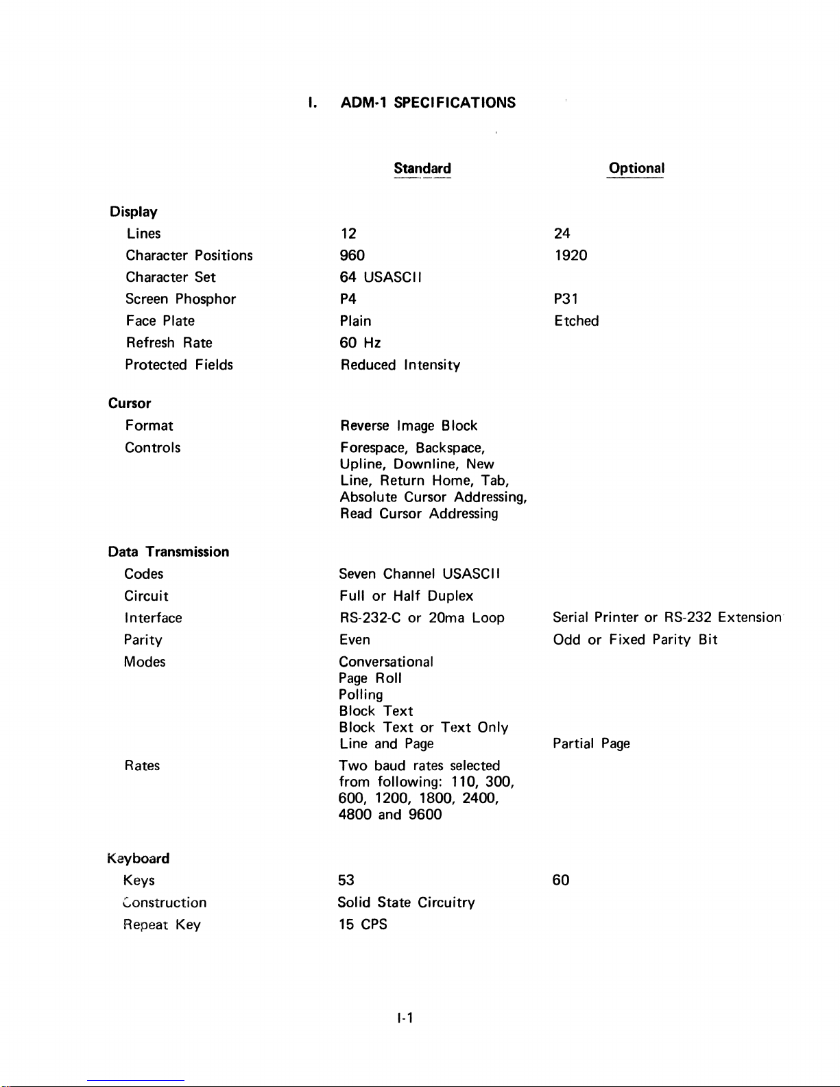
I.
ADM·'
SPECIFICATIONS
Display
Lines
Character Positions
Character
Set
Screen Phosphor
Face Plate
Refresh Rate
Protected
Fields
Cursor
Format
Controls
Data Transmission
Codes
Circuit
Interface
Parity
Modes
Rates
Standard
12
960
64
USASCII
P4
Plain
60
Hz
Reduced Intensity
Reverse Image Block
Forespace, Backspace,
Upline, Downline,
New
Line, Return Home, Tab,
Absolute Cursor Addressing,
Read Cursor Addressing
Seven Channel USASCII
Full
or
Half Duplex
RS-232-C or
20ma Loop
Even
Conversational
Page Roll
Polling
Block
Block
Text
Text
or
Text
Only
Line and Page
Two baud rates selected
from
following: 110, 300,
600, 1200, 1800, 2400,
4800
and
9600
Optional
24
1920
P31
Etched
Serial Printer or RS-232 Extension'
Odd
or
Fixed Parity Bit
Partial Page
Keyboard
Keys
Construction
Repeat
Key
53
Solid State Circuitry
CPS
15
1-1
60
I.
ADM-1
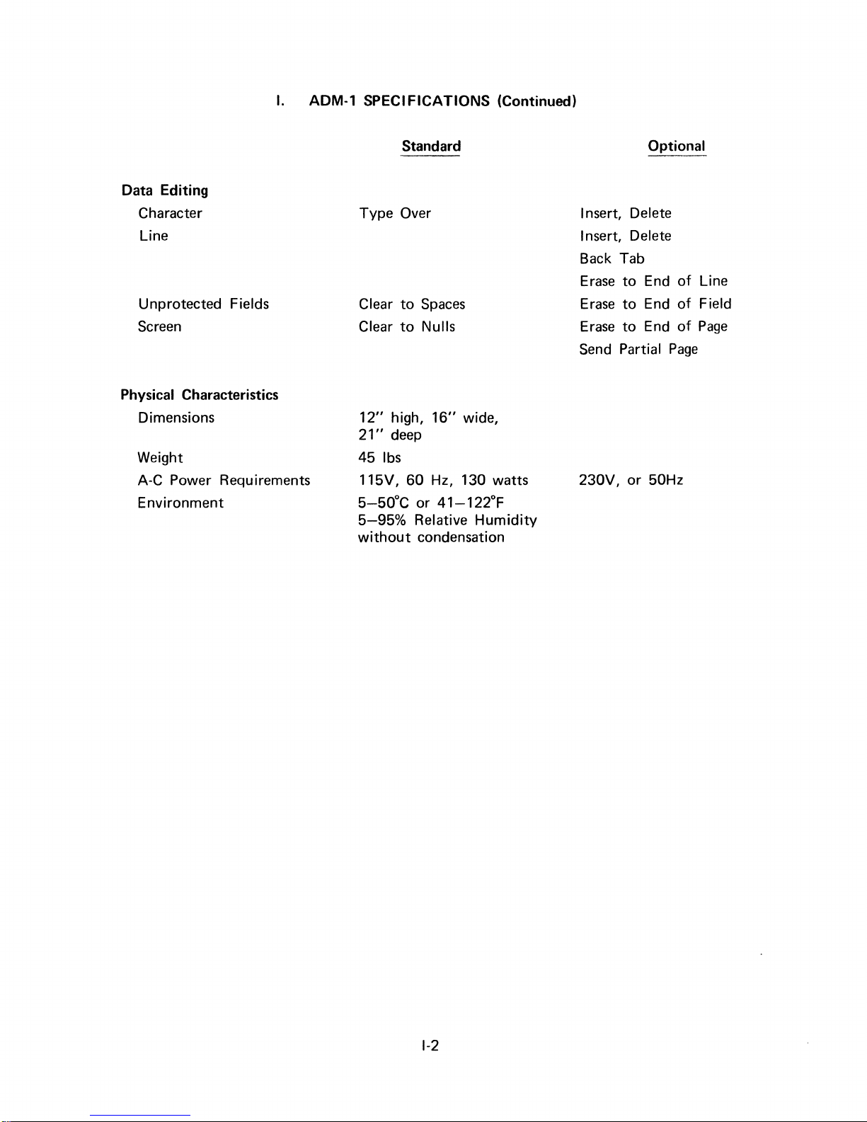
SPECIFICATIONS (Continued)
Data Editing
Character
Line
Unprotected
Screen
Fields
Physical Characteristics
Dimensions
Weight
A-C Power Requirements
Environment
Standard
Type Over
Clear
to
Spaces
Clear
to
Nulls
12"
high,
16"
wide,
21"
deep
451bs
115V, 60 Hz, 130 watts
5-50°C
5-95%
without
or
41-122°F
Relative
condensation
Humidity
Optional
I nsert, Delete
I nsert, Delete
Back Tab
Erase
to
End
Erase
to
End
Erase
to
End
Send
Partial
230V, or 50Hz
Page
of
of
of
Line
Field
Page
1-2
II.
THEORY
OF
OPERATION
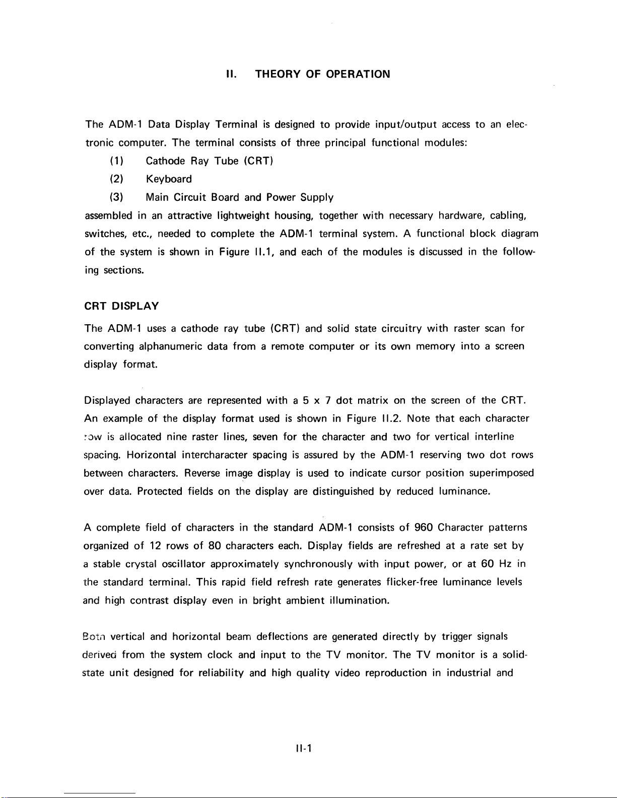
The ADM-1 Data Display
tronic
computer. The
(1) Cathode Ray
Terminal
terminal
Tube
consists
(CRT)
(2) Keyboard
(3) Main
assembled
in
switches, etc., needed
of
the
system
Circuit
an
attractive
to
is
shown in Figure
Board and Power
lightweight
complete
11.1,
ing sections.
CRT
DISPLAY
The ADM-1
converting
display
uses
a cathode ray
alphanumeric data
format.
tube
from
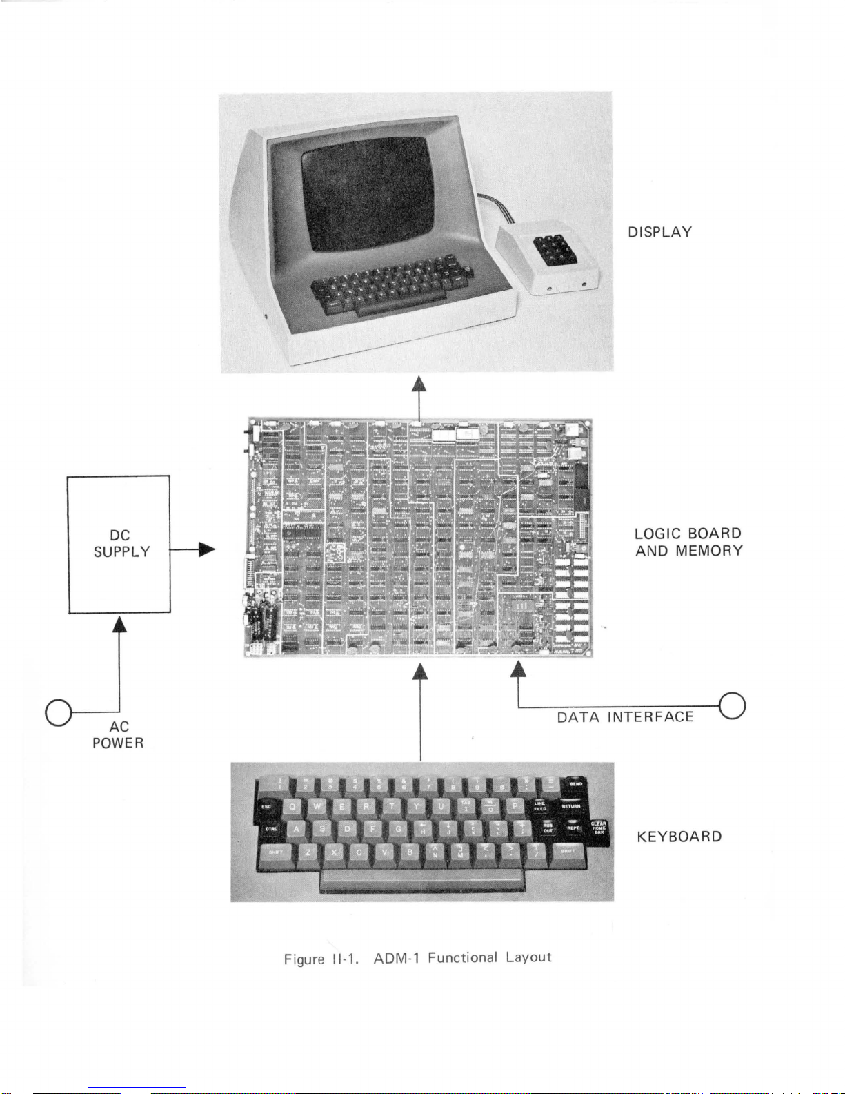
Displayed characters are represented
is
designed
of
to
provide
three principal
input/output
functional
Supply
housing, together
with
necessary hardware, cabling,
the ADM-1 terminal system. A
and each
(CRT)
a remote
with
a 5 x 7
of
the
modules
and solid state
computer
dot
or
matrix
circuitry
its
own
on
access
modules:
functional
is
discussed in
with
memory
the
screen
to
an
block
the
raster scan
into
a screen
of
the
elec-
diagram
follow-
for
CRT.
An
example
~ow
is
spacing.
of
the display
format
allocated nine raster lines,
Horizontal
intercharacter spacing
used
seven
between characters. Reverse image display
over data. Protected fields on
complete
A
organized
a stable crystal
the
standard
and high
Botn
vertical and
derived
unit
state
field
of
contrast
from
designed
of
characters in
12 rows
of
oscillator
terminal.
display even in
horizontal
the system
for
This
reliability
the
display are distinguished
the
standard ADM-1 consists
80
characters each. Display fields are refreshed
approximately
rapid field refresh rate generates flicker-free luminance levels
bright
beam deflections are generated
clock
and
input
and high
is
shown in Figure
for
the character and
is
assured
is
used
by
to
synchronously
ambient
to
quality
illumination.
the
TV
video
11.2.
Note
two
for
the ADM-1 reserving
indicate cursor
by
with
input
directly
monitor.
The
position
reduced luminance.
of
960
power,
by
TV
reproduction
that
each character
vertical
interl
two
dot
ine
rows
superimposed
Character patterns
at
a rate set
or
at
60
Hz in
trigger signals
monitor
is a solid-
in industrial and
by
11-1
DISPLAY
DC
SUPPLY
AC
POWER
L----
DATA
LOGIC
AND
MEMORY
---O
INTERFACE
KEYBOARD
BOARD
Figure
11-1.
ADM
-1 Functional
Layout
•
• •
• •
•
•••••
•
• •
• •
• •••
• •
• •
• •••
• •
• •
• •••
• ••
• •
•
•
•
• •
• ••
• •••
• •
•
•
• •
• •
• •
• •••
•
•
•
•
•
•
•
•
•
•
• •
•
commercial installations. Theory
of
this manual.
KEYBOARD
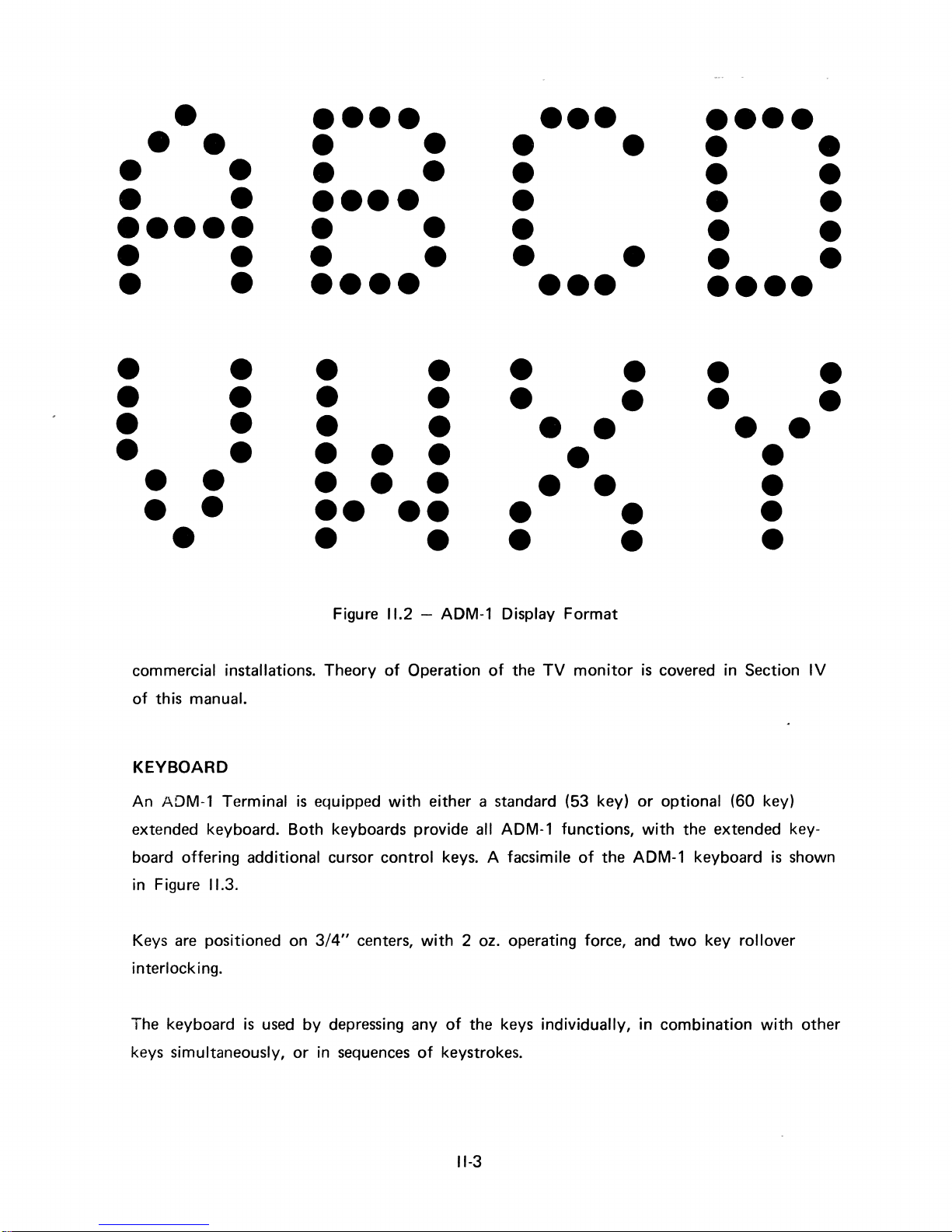
An ADM-1 Terminal
extended keyboard. Both keyboards provide
• •
•
•
• •
• • •
• • •
•• ••
• •
Figure
is
equipped
11.2
- ADM-1 Display Format
of
Operation
with
• •
•
•
•
•
• •
•
• •
of
the
TV
monitor
either a standard (53 key)
all ADM-1 functions,
• •
•
• •
•
is
covered in Section
or
optional (60 key)
with
the extended key-
• •
•
•
•
•
IV
board offering additional cursor control keys. A facsimile
in Figure
Keys
interlocking.
The keyboard
keys simultaneously,
11.3.
are
positioned on
is
used
or
3/4"
by
in
centers,
depressing any
sequences
with 2 oz.
of
of
the ADM-1 keyboard
operating force,
of
the keys individually, in combination
keystrokes.
11-3
and
two
is
key rollover
with
shown
other
[IJ
CJ
[!]
OJ
[I]
IT]
OJ
IT]
OJ
[J [J
D I
SEND
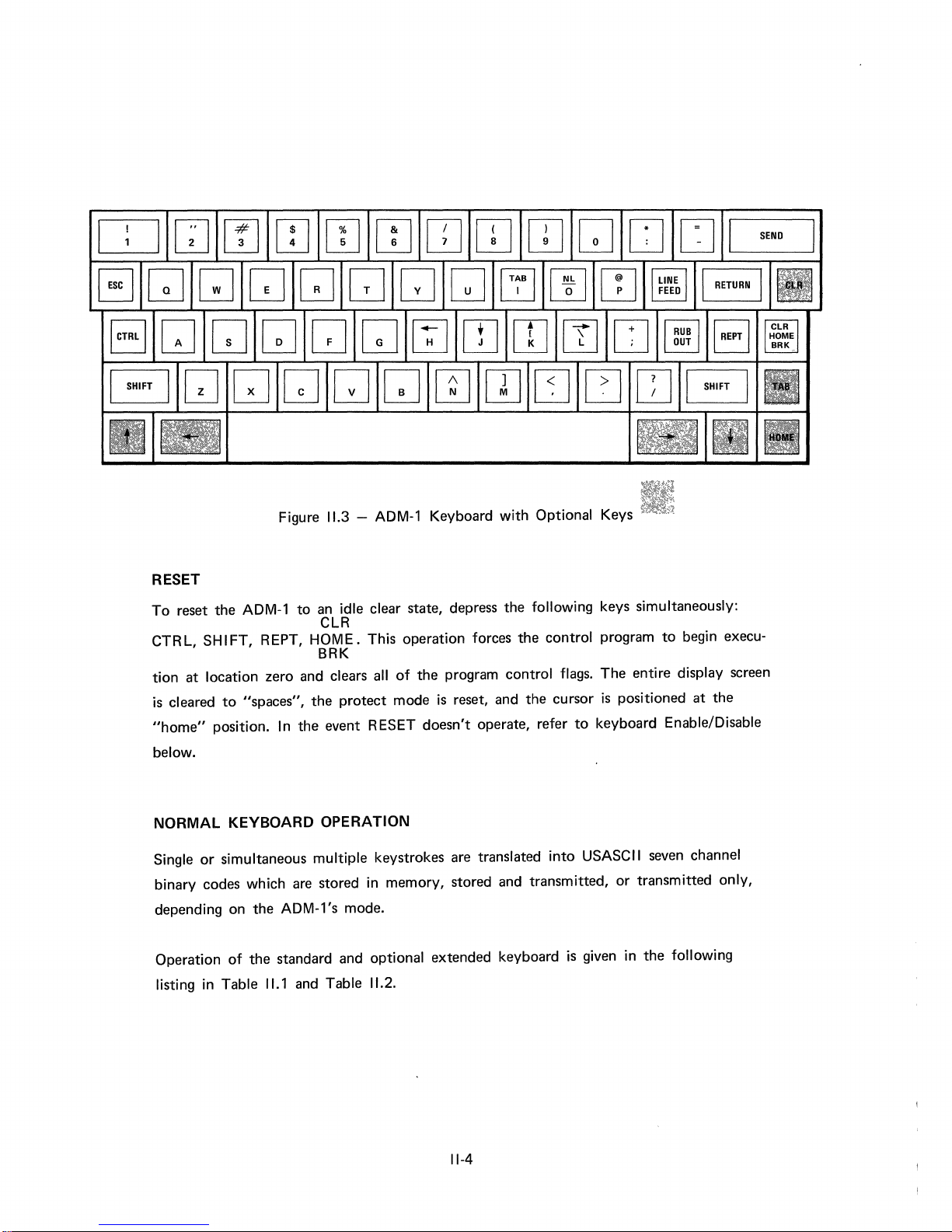
Figure
RESET
To
reset the ADM-1
CTRL,
tion at location zero
is
"home"
below.
NORMAL
Single
binary codes which
depending
Operation
SHIFT, REPT, HOME. This operation forces the control program
cleared
to
"spaces", the protect mode
position. In the event RESET doesn't operate, refer
KEYBOARD
or
simultaneous multiple keystrokes
on
the ADM-1
of
the standard
11.3
- ADM-1 Keyboard
to
an
idle clear state,
CLR
BRK
and
clears all
OPERATION
are
stored in memory, stored
's
mode.
and
of
the program control flags. The entire display
optional extended keyboard
depress
is
reset,
are
with
Optional Keys
the following keys simultaneously:
to
and
the cursor
translated
and
transmitted,
into
is
positioned at the
to
keyboard Enable/Disable
USASCII
is
given in the following
seven
or
transmitted only,
begin execu-
screen
channel
listing in Table
11.1
and
Table
11.2.
11-4
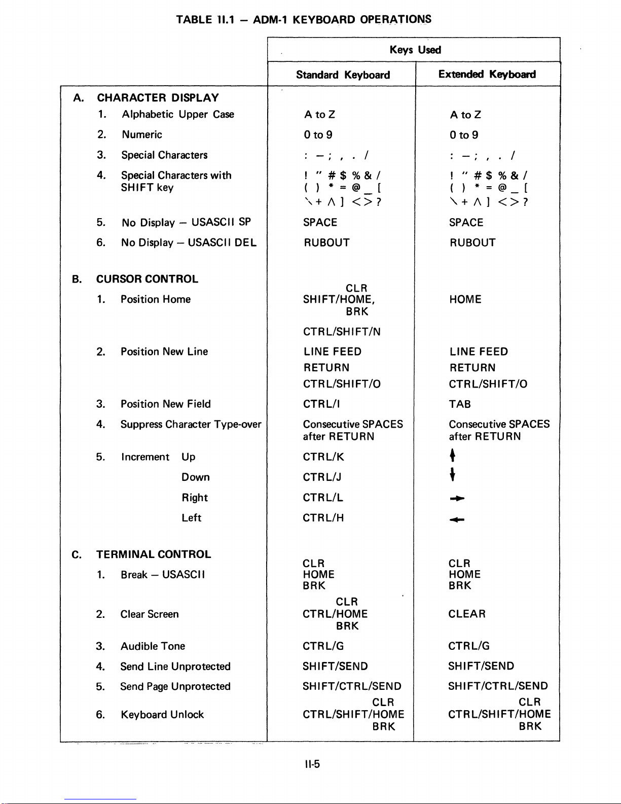
TABLE
11.1
- ADM-1
KEYBOARD
OPERATIONS
Keys Used
A.
CHARACTER DISPLAY
1.
Alphabetic Upper
2.
Numeric
3.
Special Characters
4.
Special Characters
SHIFT
5.
No Display - USASCII
6.
No Display - USASCII
CURSOR CONTROL
B.
1.
Position Home
key
2. Position New Line
Case
with
SP
DEL
Standard Keyboard
AtoZ
o
to
9
-"
1"#$%&/
()*=@-[
',+/\]
SPACE
RUBOUT
SHIFT/HOME,
CTR LlSH I FT /N
LINE FEED
RETURN
CTRLlSHIFT/O
/
<>?
CLR
BRK
Extended Keyboard
AtoZ
Oto9
-"
!
"#$%&/
/
( ) * = @ [
,,+
/\]
<>?
SPACE
RUBOUT
HOME
LINE
FEED
RETURN
CTR LlSH I
FT
/0
3. Position New Field
4.
Suppress
5. Increment Up
C.
TERMINAL
1.
Break - USASCII
2.
Clear
3. Audible Tone
Send
4.
5.
Send
6.
Keyboard Unlock
CONTROL
Screen
Line Unprotected
Page
Character Type-over
Down
Right
Left
Unprotected
CTRLlI
Consecutive
after R ETU R N
CTRLlK
CTRLlJ
CTRLlL
CTRLlH
CLR
HOME
BRK
CTRLlHOME
CTRLlG
SHIFT/SEND
SHIFT/CTRLlSEND
L/SH I FT /HOM E
CTR
SPACES
CLR
BRK
CLR
BRK
TAB
Consecutive SPACES
after R ETU R N
CLR
HOME
BRK
CLEAR
CTRLlG
SHIFT/SEND
SHIFT/CTRLlSEND
CLR
CTR
LlSH 1FT/HOME
BRK
11-5
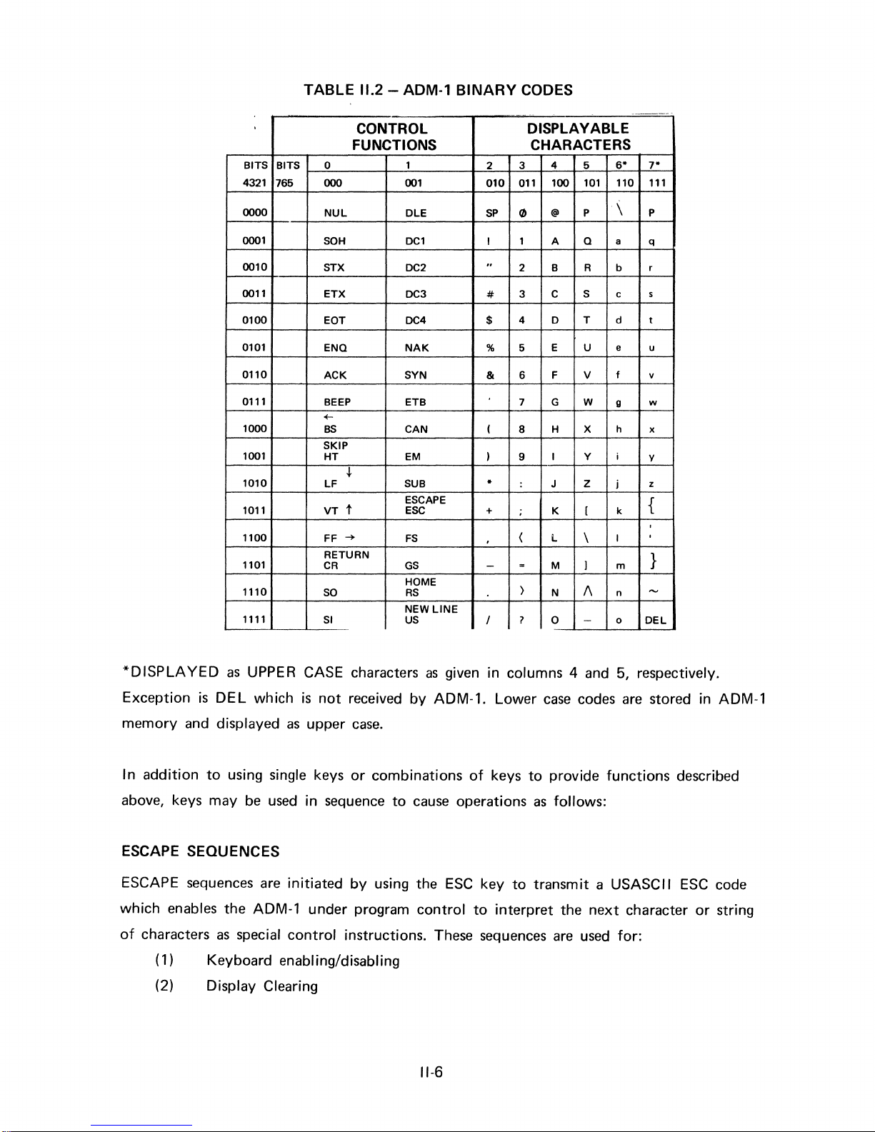
TABLE
11.2
- ADM·1
BINARY
CODES
,
BITS
4321
0000
0001
0010
0011
0100
0101
0110
0111
1000
1001
1010
1011
1100
1101
1110
1111
BITS
765
CONTROL DISPLAYABLE
FUNCTIONS CHARACTERS
0 1
000
NUL
SOH
STX
ETX
EOT
ENQ
ACK
BEEP
+-
BS
SKIP
HT
~
LF
VT
t
FF
~
RETURN
CR
SO
SI
001
OLE
DCl
OC2
DC3
DC4 $
NAK
SYN
ETB
CAN
EM
SUB
ESCAPE
ESC
FS
GS
HOME
RS
NEW
LINE
US
2
010
SP
I 1 A
..
#
% 5
&
(
)
-
+
.
-
I
4
3
011
100
(/)
@
2 B R
3 C
4 0 T d
E
6 F V
7
G
8 H X
I Y
9
:
J
;
K
(
L
=
M
}
N
?
0
5
101
P
Q
S C
U
W
Z
[
\
)
"
-
6-
110
\
a q
b r
e
f v
9
h x
i
j z
k
I
m
n
0
DEL
7-
111
P
5
t
u
w
Y
{
,
,
}
.....
*DISPLAYED
Exception
memory and displayed
In
addition
above, keys may
as
UPPER CASE characters
is
DEL
which
to
using single keys
be
used
is
not
as
upper
in sequence
ESCAPE SEQUENCES
ESCAPE sequences
which enables the
of
characters
as
are
ADM-l
special
initiated
under program
control
(1) Keyboard enabling/disabling
(2) Display Clearing
as
given in columns 4 and 5, respectively.
received
by
ADM-l.
Lower
case.
or
combinations
to
cause
by
using the
control
of
keys
operations
ESC
key
to
interpret
to
as
to
transmit a USASCII
instructions. These sequences
11-6
case
codes
are
stored in
provide functions described
follows:
ESC
code
the
next
are
used
character
for:
or
string
ADM-l
(3) Field Protection Control
(4)
(5) Absolute Cursor Addressing/Cursor Address
(6) Data Editing (optional)
Details
ENABLE/DISABLE KEYBOARD
These
which transmits the following
ESC
ESC
Since
to
be
CTRL/SHIF~/HOME
Message
of
specific
functions
Transmissions Control
sequences
are
normally
follow:
used
sequences:
when the
# disables all keyboard functions except KEYBOARD
" restores keyboard control
ESC # sequence
unlocked by simultaneously depressing:
CLR
BRK
may
be
accidentally initiated manually, the keyboard
unlocks keyboard
ADM-l
Read
is
connected on-line
to
a computer
UNLOCK
will
need
CLEAR
The
Locally the operator
by
keyboard).
By operator
may
ESC
ESC
ESC
ESC
Upon completion, the cursor
ADM-l
use
of
be
DISPLAY
screen
the CTRL
or
computer control, the entire display may be cleared
cleared
to
+
*
may
be
can
clear the foreground (unprotected characters)
CLR
and
HOME keys (or the
BRK
either "spaces"
clear foreground
clear all
clear foreground
clear all
to
to
cleared in
or
to
spaces
to
NUL
will
be
several
to
NULS by the
spaces
NUL
in the
first
ways:
CTRL
and
CLEAR key on the
or
use
of
the following
unprotected position on the
to
"space"
60
only
the foreground
escape
screen.
codes
key
sequences:
11-7
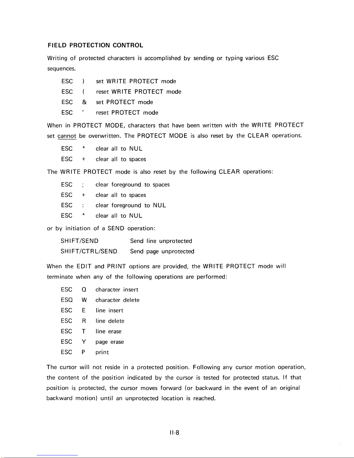
FIELD
PROTECTION CONTROL
Writing
sequences.
When
set
The
of
protected
ESC
ESC reset WRITE PROTECT
ESC &
ESC reset PROTECT
in
PROTECT
cannot
WR
ESC
be
overwritten.
ESC
ESC
ESC
ESC
ESC clear foreground
*
+
ITE PROTECT
+
*
characters
set
WR
ITE
PROTECT
set
PROTECT
MODE, characters
The
clear all
clear
clear foreground
clear all
clear all
all
mode
to
to
to
to
NUL
spaces
spaces
NUL
is
accomplished
mode
mode
that
PROTECT
is
also reset by
to
spaces
to
NUL
mode
mode
have been
MODE
by
sending
is
also reset
the
following CLEAR operations:
or
written
typing
with
by
the
various ESC
the
WRITE
CLEAR
PROTECT
operations.
or
by
initiation
SHIFT/SEND
SHIFT/CTRLlSEND
When
terminate
The
the
position
the
EDIT
when
ESC
ESQ
ESC E line insert
ESC R line delete
ESC
ESC
ESC P
cursor
content
Q
W
T
y
will
of
is
protected,
not
the
of
a SEND
and
PRINT
any
of
character
character
line erase
page erase
print
reside
position indicated by
the
operation:
Send line
Send
options
the
following
insert
delete
in a protected
cursor
unprotected
page
unprotected
are provided,
operations
position. Following any
the
moves forward (or
are
cursor
the
WRITE
performed:
is
tested
backward
PROTECT
cursor
for
protected
in
the
motion
event
mode
status. If
of
an original
will
operation,
that
backward
motion)
until an
unprotected
location
11-8
is
reached.
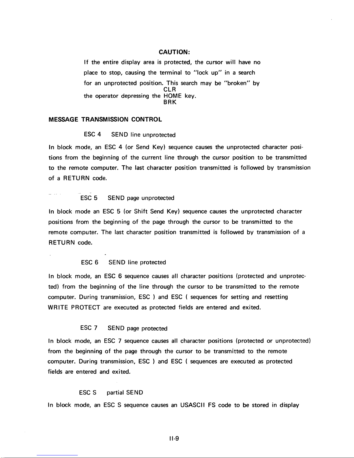
If
the
place
CAUTION:
entire display area
to
stop, causing the terminal
is
protected,
to
the
cursor will have no
"lock
up"
in
a search
for an unprotected position. This search may be
CLR
the
operator depressing
the
HOME
key.
BRK
MESSAGE TRANSMISSION CONTROL
ESC
4 SEND line unprotected
In
block mode, an
tions from
to
the
of
a RETURN code.
the
remote computer. The last character position transmitted
ESC
In
block mode an
positions from
ESC
4 (or Send Key) sequence causes
beginning
5
ESC
the
beginning
of
the
SEND page unprotected
5 (or Shift Send Key) sequence causes
of
current
the
page through
line through the cursor position
the
cursor
remote computer. The last character position transmitted
RETURN code.
"broken"
the
unprotected character posi-
is
the
to
be transmitted
is
followed by transmission
by
to
be transmitted
followed by transmission
unprotected character
to
the
of
a
SEND line protected
6
ESC
6 sequence causes
of
the
In
block mode, an
ted) from
the
ESC
beginning
computer. During transmission,
WR
ITE
PROTECT are executed as protected fields are entered and exited.
ESC
7
SEND page protected
In
block mode, an
the
from
beginning
ESC
7 sequence causes
of
the
page through
computer. During transmission,
fields are entered and exited.
partial SEND
S
ESC
S sequence causes an USASCII FS
In
block mode, an
ESC
all
character positions (protected and unprotecline through the cursor
ESC
ESC
) and
) and
ESC
( sequences for setting and resetting
all
character positions (protected
the
cursor
ESC
to
( sequences are executed as
to
be transmitted
be transmitted
code
to
to
to
the
protected
be stored
the
remote
or
unprotected)
remote
in
display
11-9
memory
is
encountered, then advances
through the
at home position,
at the cursor location. The cursor backspaces
next
FS
code.
or
the
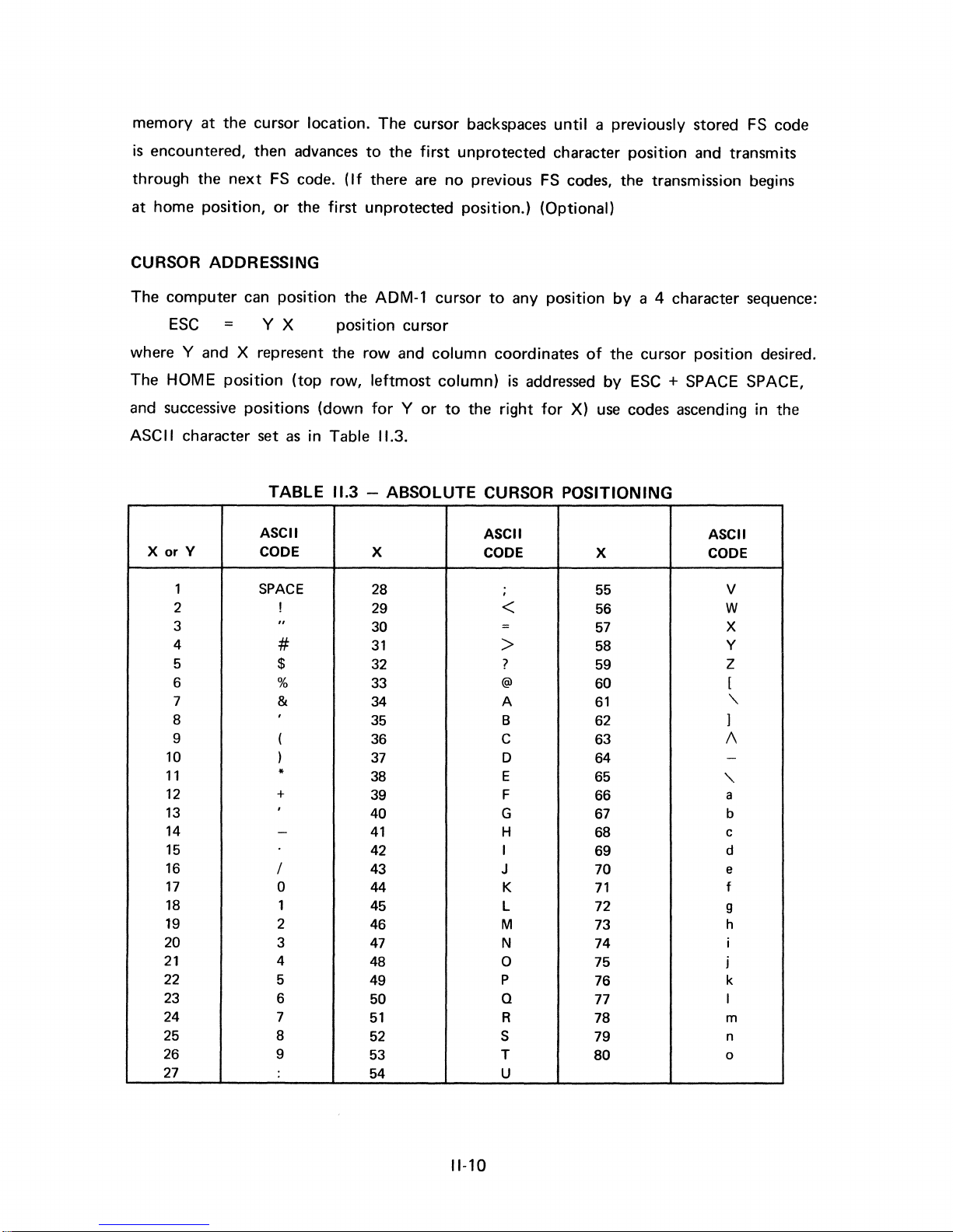
CURSOR ADDRESSING
The
computer
can position the ADM-1 cursor
to
the
first
unprotected character position and transmits
(If
there are no previous
first
unprotected position.) (Optional)
to
any position
until
a previously stored
FS
codes, the transmission begins
by
a 4 character sequence:
FS
code
ESC
where
HOME position (top row,
The
=
YX
position cursor
Y and X represent the
and successive positions (down
ASC II character set
X
or
Y
as
TABLE
ASCII
CODE
in Table
11.3
1 SPACE
2
3
4
5
!
"
#
$
6 %
7 &
8
9
10
11
12
13
14
,
(
)
*
+
,
-
15
16
17
18
19
20
21
22
23
24
25
26
I
0
1
2
3
4
5
6
7
8
9
27
row
and
leftmost
for Y or
column
column)
to
coordinates
is
the
right
addressed
for
X)
of
the cursor position desired.
by
ESC
use
codes ascending in the
11.3.
- ABSOLUTE CURSOR POSITIONING
ASCII
X
28
29
30
31
32
33
34
35
CODE X
,
<
=
>
?
@
A
B 62
55
56
57
58
59
60
61
36 C 63
37
38
39
40 G
41
42
43
44 K
45
46
47
48
49
50
51
52
53
D 64
E
F
65
66
67
H
I
J
68
69
70
71
L 72
M
N
0
P
Q
R
S
T
73
74
75
76
77
78
79
80
54 U
+ SPACE SPACE,
ASCII
CODE
V
W
X
Y
Z
[
"-
1
1\
-
"-
a
b
c
d
e
f
9
h
i
j
k
I
m
n
0
11-10

After
If
that
tion
the
position
in
the
'X'
coordinate
is
is
loaded,
protected,
the
the
cursor automatically skips
direction it previously moved.
position
An
of
the cursor
ESC
? sequence causes
is
tested for protected status.
to
the
first
unprotected
the
Y and X coor-
loca-
dinates
be transmitted
ESC
of
the
cursor followed by a
to
the
computer.
? read cursor position
EDIT OPERATION (OPTION)
ESC
Q character insert
a)
b)
Resets WRITE PROTECT mode.
Moves
the
character under
(or field) one space
c)
a)
b)
Write a space
that
position.
ESC
W character delete
at
Resets WRITE PROTECT mode.
Deletes
the
character under the cursor by moving
CR
code (expressed as three USASCII characters)
(Y
X CR)
the
cursor and
to
the
right.
the original position
of
all
following characters on
the
cursor and leaves
all
following characters on
the
that
cursor
to
line
at
that
line
or
field one space
c) Writes a 'space'
d) Cursor does
ESC
E
a)
Is
not
b) Resets
c)
Inserts a line
moving
d) Bottom line
e)
At
completion cursor
not
line insert
executed
WRITE PROTECT mode.
of
the
contents
is
to
in
the
last position
move.
if
PROTECT MODE
unprotected spaces
of
that
line and
lost.
is
at
first character position
the
left.
of
the
line
is
set.
at
the
line occupied by
all
lines below down
or
field.
of
inserted line.
the
one
cursor by
line.
11-11
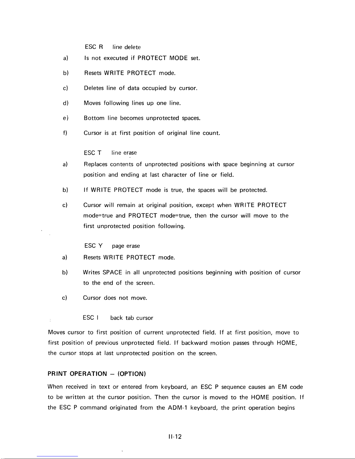
ESC
R line delete
a)
Is
not
executed
if
PROTECT MODE
set.
b)
Resets
WRITE PROTECT mode.
c)
Deletes line
of
data occupied by cursor.
d) Moves
following lines up one line.
e)
Bottom
line becomes unprotected
spaces.
f) Cursor
is
at
first
position
of
original line count.
ESC
T line
erase
a)
Replaces contents
of
unprotected positions
with
space
beginning at cursor
position
and
ending at last character
of
line
or
field.
b)
If
WRITE PROTECT mode
is
true, the
spaces
will
be
protected.
c) Cursor
will
remain at original position, except when WRITE PROTECT
mode=true and PROTECT mode=true, then the cursor
will
move
to
the
first unprotected position
following.
ESC
Y
page
erase
a)
Resets
WRITE PROTECT mode.
b) Writes
SPACE in all unprotected positions beginning
with
position
of
cursor
to
the end
of
the
screen.
c)
Cursor
does
not
move.
ESC
I
back tab cursor
Moves cursor
to
first
position
of
current unprotected field.
If
at first position, move
to
first
position
of
previous unprotected field.
If
backward
motion
passes
through HOME,
the cursor stops at last unprotected position on the screen.
PRINT
OPERATION
- (OPTION)
When received in
text
or
entered from keyboard,
an
ESC
P sequence
causes
an
EM
code
to
be
written
at the cursor position. Then the cursor
is
moved
to
the HOME position.
If
the
ESC
P command originated from the ADM-1 keyboard, the
print
operation begins
11-12
immediately;
if
the command
is
from the computer, the
print
operation begins following
the termination
of
the
message
procedure.
ESC
P
print
Printing takes place in the following manner:
1.
CR
LF
NUL
2.
Each
line
of
text
followed
by
CR
LF
NUL
Transmission
of
trailing
spaces
is
suppressed
in order
to
reduce printing time.
The
PRINT operation terminates when the cursor
reaches
the
EM
code at which time a
final
CR
LF
NUL
is
sent
to
the printer.
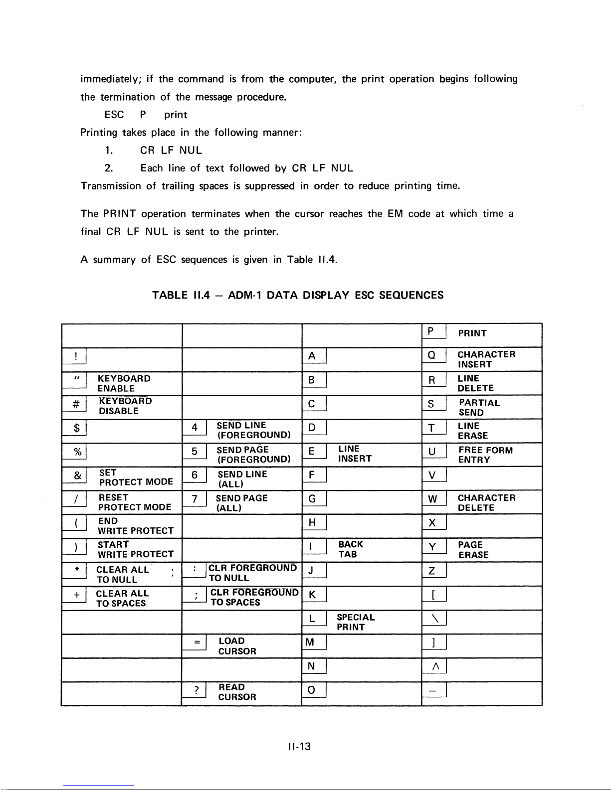
A summary
of
ESC
sequences
is
given in Table
11.4.
TABLE
11.4 -ADM-l
DATA
DISPLAY
ESC
SEQUENCES
~
PRINT
~
~
~
CHARACTER
INSERT
~
KEYBOARD
~
LB-J
LINE
ENABLE
DELETE
2J
KEYBOARD
l£J
l£J
PARTIAL
DISABLE
SEND
~
W
SEND LINE
~
LI-J
LINE
(FOREGROUND)
ERASE
~
~
SEND PAGE
LU
LINE
~
FREE FORM
(FOREGROUND)
INSERT
ENTRY
~
SET
W
SEND LINE
LU
~
PROTECT MODE
(ALL)
~
R~SET
W
SEND PAGE
~
~
CHARACTER
PROTECT MODE
(ALL)
DELETE
~
END
UiJ
~
WRITE PROTECT
~
START
l!-J
BACK
~
PAGE
WRITE PROTECT TAB
ERASE
~
CLEAR
ALL
,
~CLR-~OREG~OUND
LU
~
TO
NULL
.
TO
NULL
~
CLEAR
ALL
TO
SPACES
~C[RFOREGROUND
' TO
SPACES
l!U
W-J
l!-J
SPECIAL
WJ
PRINT
~
LOAD
!U
W
CURSOR
JU
~
UJ
READ
~
~
CURSOR
11-13

III.
MICROPROGRAMING CONTROL
The organization
is
terminal
description
given in general fashion in the block diagram
of
logic
drawing 129311,
2,
sheet
contains a detailed functional block diagram
of
data transmission
for
the ADM-1 follows. Specific reference should
sheets
1 through 16, in Appendix C.1. In particular, Drawing 129311,
and
control
TO VIDEO MONITOR
DISPLAY
SECTION
MEMORY
SECTION
(RAM)
for
the ADM-1 interactive data display
of
Figure
of
the ADM-1 logic.
111.1.
be
A detailed
made
to
schematic
CONTROL
KEYBOARD
Figure
The basic concept
ity
assigned
to
of
the display section (about 20-30% utilization)
control section which
111.1
- ADM-1 Data
the ADM-1 data organization
has
approximately 70-80% utilization.
SECTION
(ROM)
Flow
Block Diagram
is
memory timesharing,
The memory sharing organization provides greater reliability
by
using fewer components
to
provide
both
functions.
111-1
TRANSMITTER
and
second
of
display
RECEIVER
with
priority
and
control
DATA
r+-
SIGNAL
~
INTERFACE
highest prior-
given
to
the
operations
Data
information
and
control
commands
are
transferred
to
the
different
components over
a tri-state (memory, control, timing)
The display section is comprised
of
bus.
four
sub-sections
as
follows:
(1) Parallel-Serial Converter
(2) Character Generator
(3) Row Refresh Logic
(4)
The memory section
(12 lines
1920 words
Timing
of
80
to
Control
is
a standard RAM memory
characters) in the standard
give 24 lines
of
80
character display.
ADM-l
of 8 bit
display. A factory
The memory section includes the conversion logic necessary
display cursor position. Binary codes
in Table
Included
11.2
above.
with
the keyboard assembly
for
cursor position
are
the electronics
are
for
words and
can
store
option
for
maintaining knowledge
given
as
USASCII equivalents
encoding key strokes
960
is
provision
words
of
of
to 8 bit
parallel data codes,
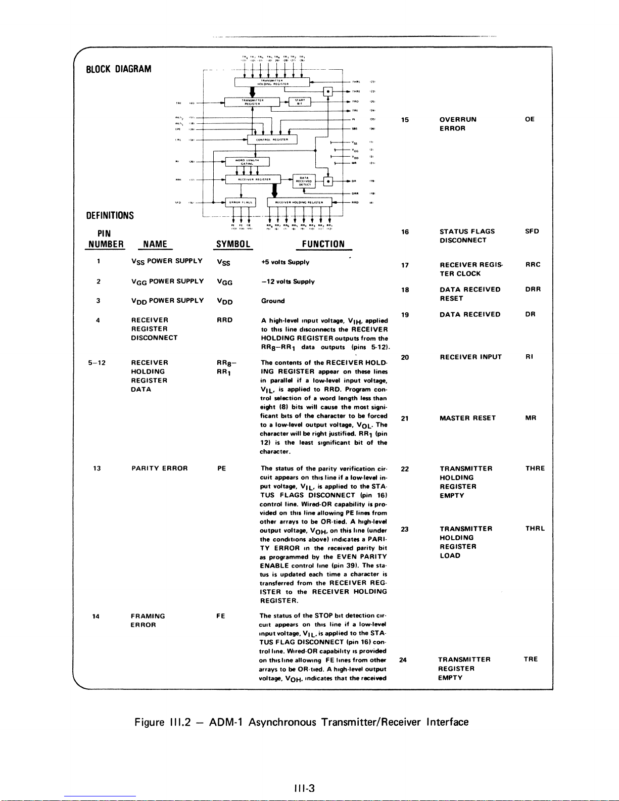
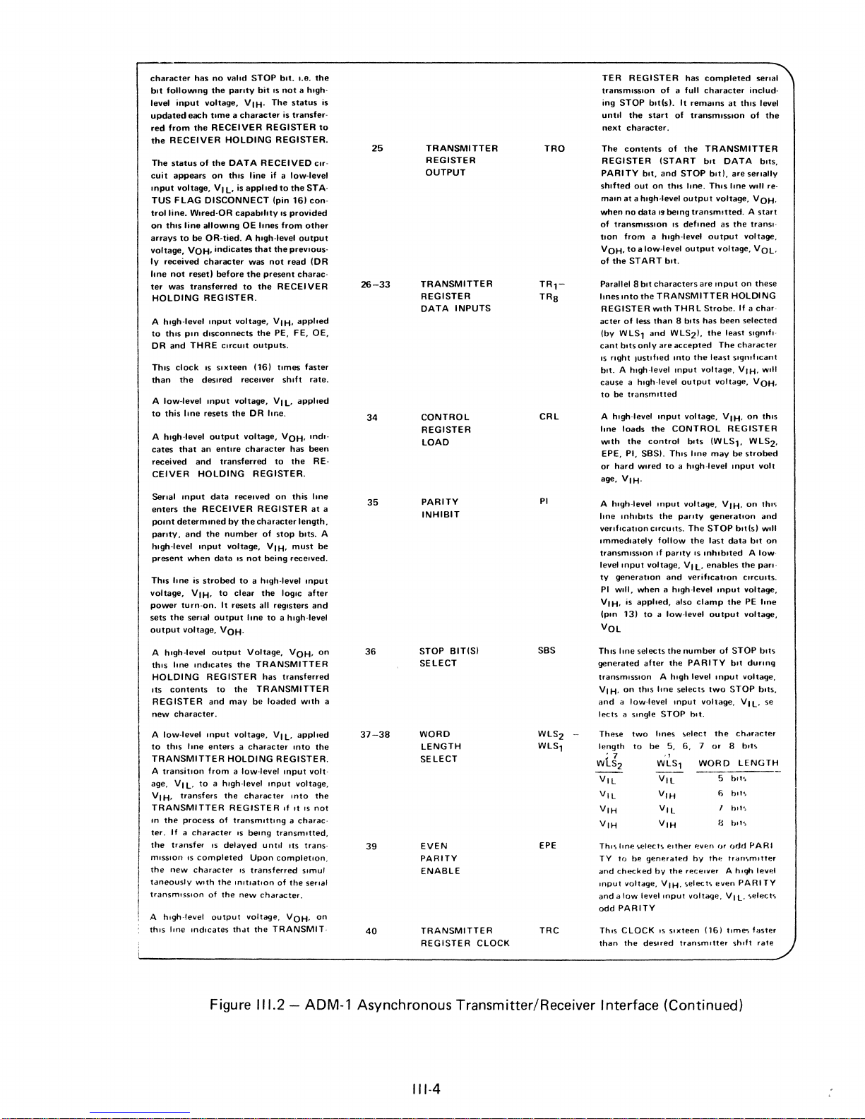
The transmitter/receiver
which accepts serial 9, 10
an
RS232C
trol
section. Likewise, the transmitter receiver
control
or
section and transmit the appropriate serial
data signal interface.
for
further
Information
information
transfer
standard functions
may
be
extended
as
well
as
strobe
is
a standard 1402
or
11
bit
20ma current loop interface and transmits 8
See
Figure
111.2
on the 1402/1602 transmitter/receiver.
is
controlled in the ADM-1
are
provided
by
adding up
by
to
six additional
program language and the structure
Information
under microprogram
is
transferred between functional units
control.
This
information
and
repeat signals.
or
1602 LSI chip serial asynchronous device
patterns (depending upon
can
receive 8
bit
pattern
word
structure
bit
parallel words
bit
parallel words from the
to
a computer over the
option)
to
the con-
below and Drawing 129311, sheet 13 in Appendix C
by
the
read
only
memory, ROM. The
two
pages
of
256 8
pages.
of
the extendable microprogrammed control.
transfer consists
bit
words
each.
These functions
This section describes the micro-
by
way
of
the tri-state bus, TSB,
of
eight
bit
characters
from
111-2
BLOCK
DIAGRAM
DEFINITIONS
PIN
NUMBER
VSS POWER SUPPLY
2
3 VDD
4
5-12
13
14
VGG
RECEIVER RRD
REGISTER
DISCONNECT
RECEIVER
HOLDING
REGISTER
DATA
PARITY
FRAMING
ERROR
NAME
POWER SUPPLY
POWER SUPPLY
ERROR
.,
.,
eM
")'''.'''\'
SYMBOL
VSS
VGG
VDD
RRSRR,
PE
FE
~~.
:~'
~,~
~I~~
~,~. ~.:~
~~~
~,~:
FUNCTION
+5 volts SupplV
-12
volts Supplv
Ground
A high-level Input voltage. VIH. applied
to
th,s
line dIsconnects
HOLDING REGISTER
RRS-RR,
The
ING REGISTER
parallel if a low-level
in
VIL.
trol selection
eight (SI bits will cause
ficant
to
a low-level
character will be right justified_
121
character.
The status
cuit
put
TUS
control
vided on th,s line allowing
other
output
the
TY ERROR
as programmed
ENABLE
IUs
transferred from
ISTER
REGISTER.
The
CUlt
Input voltage. VIL. is applied
TUS
trol line. WIred-OR capabilltv
on
th,s line
arravs
voltage. VOH. Indicates
data
contents
appaars
voltage. VIL. is applied
conditIons
is
status
appears
of
is applied
of a word
bIts
of
the
output
is
the
least SIgnificant
of
the
on
FLAGS DISCONNECT
line. Wired-OR capabilitv is pro-
arreys
to
voltage. VOH. on this line (under
'"
control
updated
to
the
of
the
on
FLAG DISCONNECT (pin 161 con-
allOWIng
to
be OR-tIed. A hlgh·level
the
RECEIVER
outputs
from
(pins
outputs
the
RECEIVER HOLD-
appear
to
RRD. Program con-
length
the
character
voltage. VOL.
paritv
verification cir-
thIs line if a low-level in-
be OR·tied. A hIgh-level
abovel,ndlCates
the
received paritv
bV
the
EVEN PARITY
line (pin 391. The sta-
each time a character
the
RECEIVER REG-
RECEIVER HOLDING
STOP bIt detection
thIS line if a low-level
FE lines from
that
on
these lines
input
most
to
be forced
bit
to
PE
lines from
to
IS
the
5-121.
voltage.
1_
than
signi-
RR,
(pin
of
the STA(pin
a PARI-
the
STA-
provided
other
output
received
The
the
161
Clr-
the
bit
15
16
17
18
19
20
21
22
23
is
24
OVERRUN
ERROR
STATUS FLAGS
DISCONNECT
RECEIVER REGISTER CLOCK
DATA RECEIVED
RESET
DATA RECEIVED
RECEIVER INPUT
MASTER RESET
TRANSMITTER
HOLDING
REGISTER
EMPTY
TRANSMITTER
HOLDING
REGISTER
LOAD
TRANSMITTER
REGISTER
EMPTY
OE
SFD
RRC
ORR
DR
RI
MR
THRE
THRL
TRE
Figure
111.2 -ADM-l
Asynchronous Transmitter/Receiver Interface
111-3
character
bIt
level
updated
red
the
The
cuit
onput
TUS
trolline.
on
arrays
voltage,
ly
line
ter
HOLDING
A
to
DR
ThIs
than
A low-level
to
A
cates
received
CEIVER
Serial
enters
poont
panty,
hlgh·level
present
ThIs lone is
voltage,
power
sets
output
followong
input
each
from
the
RECEIVER
status
appears
voltage,
FLAG
Wlred·OR
thIs
line
to
be
VOH,
received
not
resetl
was
transferred
h,gh·level
thIs
pon
and
THRE
clock
the
this
hne
h,gh·level
that
mput
the
determIned
and
when
VIH,
turn-on.
the
senal
voltage,
has
voltage,
of
DISCONNECT
allowIng
OR-tied. A hlgh·level
character
REGISTER.
d,sconnects
IS
deSired
onput
resets
an
and
HOLDING
RECEIVER
the
onput
strobed
A hIgh-level
thIs
lone
ond,cates
HOLDING
ItS
REGISTER
contents
REGISTER
new
character.
A
low·level
to
this
onput
Ime
TRANSMITTER
A
transition
age,
VI
L,
H.
to a h'gh·level
transfers
VI
TRANSMITTER
In
the
process
ter.
If a character
the
transfer
miSSion
IS
new
character
h'gh·level
,nd,cates
completed
With
the
tdneously
transmiSSion
A
thIS ione
no
valid
STOP
the
panty
bit
IS
V I H.
The
time a character
RECEIVER
REGISTER
HOLDING
the
DATA
this
L,
is
applied
line
RECEIVED
if a low-level
on
VI
(pin
capabIlity
OE
lones
indicates
that
the
was
the
to
the
voltage,
the
outputs.
(161
not
present
VIH,
PE,
before
onput
CirCUIt
sIxteen
receiver
voltage,
VI
the
DR
Ime.
output
voltage,
entire
character
transferred
to
REGISTER.
data
received
REGISTER
by
the
character
number
of
voltage,
data
VIH,
IS
not
being
to a hlgh·level
to
clear
the
It
resets
all
output
registers
Ime
to a high-level
VOH'
output
Voltage,
the
TRANSMITTER
has
to
the
and
enters a character
TRANSMITTER
may
be
voltage,
loaded
VI
HOLDING
from a low-level
onput
the
charac
ter
REGISTER
of
transmitting a charac-
IS
being
IS
delayed
until
Upon
IS
transferred
the
mltlatlon
of
the
new
character.
output
Voltage,
thdt
the
TRANSMIT·
b,t.
I.e.
the
not a hIgh·
status
is
transfer-
REGISTER.
cor·
to
the
STA·
161
con·
IS
provided
from
other
output
prevIous-
read
(DR
charac·
RECEIVER
applIed
FE,
OE,
tImes
faster
shift
rate.
L,
applied
VOH,
ondl'
has
been
the
RE-
on
this
Ime
at
length,
stop
bIts.
must
received.
onput
logIC
after
and
VOH,
transferred
WIth a
L,
apploed
IOta
the
REGISTER.
Input
volt·
voltage,
Into
the
If
It
IS
not
transmitted,
ItS
trans-
completIOn,
slmul
of
the
serial
VOH,
be
on
on
TER
REGISTER
transmiSSion
is
to
25
TRANSMITTER
TRO
REGISTER
OUTPUT
26-33
TRANSMITTER
REGISTER
DATA
INPUTS
ing
STOP
until
the
next
character.
The
contents
REGISTER
PARITY
shifted
out
maon
at a hlgh·level
when
no
data
of
transmiSSion
from a hlgh·level
tIOn
VOH,
to a low·level
of
the
START
Parallel 8
lones onto
the
REGISTER
acter
of
less
(by
WLS,
cant
bits
only
IS
right
Justified
bIt,
bit
bit. A h'gh·level
cause a high-level
to
be
transmitted
34
CONTROL
CRL
REGISTER
LOAD
a
35
PARITY
INHIBIT
PI
A
A hlgh·level
lone
loads
WIth
the
EPE,
PI,
SBS),
or
hard
Wired
age,
VIH.
A
high-level
Ime
mhlblts
verificatIOn
Immediately
transmiSSIOn If
level
Input
ty
generatIOn
PI
WIll,
when a hlgh·level
VIH,
is apploed,
(pIn 131
has
of
a full
blt(sl.
It
remaIns
start
of
transmiSSion
of
the
(START
and
STOP
on
this
hne.
output
19
being
transmitted, A start
IS
deft
output
bot.
characters
TRANSMITTER
WIth
THR L Strobe.
than 8 bits
and
WLS2),
are
accepted
IOta
the
onput
output
onput
voltage,
the
CONTROL
control
bIts
Th,s
lone
to a high-level
Input
voltage,
the
panty
CirCUits.
The
follow
the
parity
and
IS
Vll,
verification
voltage,
also
to a low·level
completed
character
includ-
at
thIs
of
TRANSMITTER
bIt
DATA
bltl,
are
senally
This
Ime
Will re-
voltage,
ned
as
the
output
tranSI-
voltage,
voltage,
are
Input
on
HOLDI NG
If a
has
been
selected
the
least
s'gn,f"
The
character
least
Significant
voltage,
VIH,
voltage,
VIH,
on
REGISTER
(W
LS1, W LS2,
may
be
strobed
mput
V'H,
on
generatIOn
STOP
blt(s)
last
data
onput
output
the
bit
the
CirCUitS.
voltage,
PE lone
voltage,
inhibited A low-
enables
clamp
senal
level
the
bIts,
VOH,
VOL,
these
char·
WIll
VOH,
thIS
volt
thl<;
and
Will
on
pan-
VOL
36
37-38
BIT(S)
SELECT
WORD
LENGTH
SELECT
SBS
Th,s
lone
selects
generated
transmiSSion A high
VI H,
on
and a low-level
lects
a
These
length
• 7
WLS2
after
thiS
Single
two
to
be
the
Ime
STOP
hnes
5,
'l
WLS,
the
number
PARITY
selects
Input
!:oelect
6.
level
bIt.
7
WORD
of
Input
two
voltage,
the
or 8 b,t,
6
STOP
bIt
durong
voltage,
STOP
VI
L.
chdracter
LENGTH
bll':.
b,ts
bits,
se
STOP
e bit",
39
40
EVEN
PARITY
ENABLE
TRANSMITTER
REGISTER
CLOCK
EPE
TRC
Thlsltne\elect<.
TY
to
bp.
checked
voltage,
a
low
PARITY
CLOCK
the
generated
levellOput
deSired
and
Input
and
odd
ThIS
than
by
VIH.
IS
p.lther
the
receiver
<j,elect\
sixteen
transmitter
~vp.n
by
th~
voltage,
(16)
or
even
odd
triHl
A
VI
tIme-;,
shift
PARI
..
mltter
hU"!l
PARITY
L,
..
elect
faster
levet
..
rate
Figure
111.2
- ADM-1 Asynchronous Transmitter/Receiver I nterface (Continued)
111-4
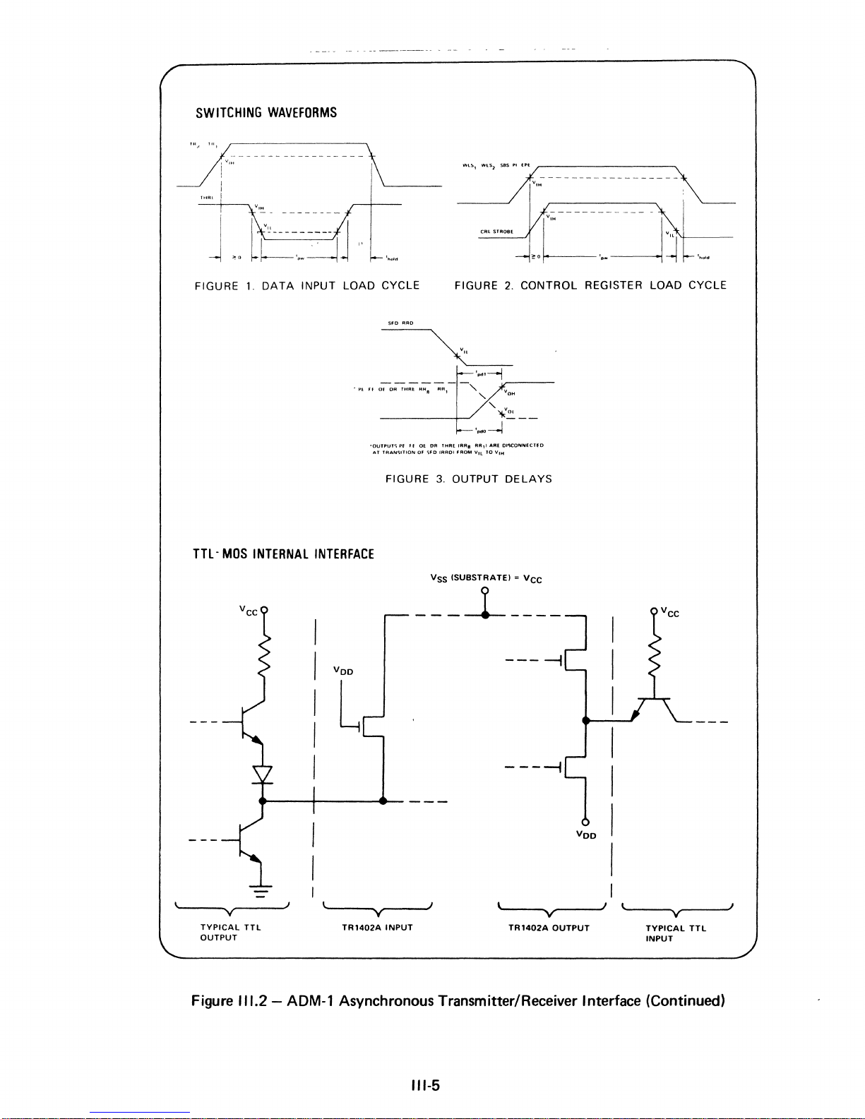
SWITCHING
WAVEFORMS
J,m
I
HIAI
!
-
J
FIGURE
TTl-
V,"
<0
[(--~~J
1.
DATA
MOS
INTERNAL
__
m_n
__
..
INPUT LOAD CYCLE
INTERFACE
~
'-----
'OUTPUT'>
AT TRAN'>ITION
FIGURE
.....
FIGURE
PF
~f
DE
DR THRl.
tAR,
Of
,>FO
IAROI FADM VIL
3.
OUTPUT
VSS ISUBSTRATEI = VCC
,
~",
sa'A"------------------L
CAL
STROeE
2.
CONTROL REGISTER LOAD CYCLE
~Ol
"
,
....
-.l---
AA,I
ARE DI'U:DNNECTfD
to
VIH
DELAYS
y
TYPICAL TTL
OUTPUT
Figure
l ....
I
111.2 -ADM-l
-----1-----
Voo
----I
L
----I
Voo
__
......
___
INPUT
-'J
~--......~"...---'I
TR1402A
OUTPUT TYPICAL
l~----~V"...-_--'I
INPUT
TTL
-
y-
TR1402A
Asynchronous Transmitter/Receiver Interface (Continued)
111·5

transmitted
MNEMONIC
in parallel
between
the
following
units:
RCV
KEY
CPR
CPC
LIT
RDR
WDR
LRC
XRS
ADD
STB
MACR
MACC
Character
BUS
CONTROL
External
Keyboard
Cursor
Cursor
Eight
Random
Random
Modulo 2 adder
UART
Switch
8 flip flops
Random
Random
bits)
transfer
between
microprogram
source
position
position
bit
literal register
access page
access page
and
(8 bits) internal,
access page
access page
via
row
character
and
interface
set
and
the
tri-state
commands
Receiver
register
buffer
buffer
accumulator
status
cleared
buffer
buffer
and
register
via
via
manually
by
row
character
bus
(see
serial
the
the
*7
set
program
counter
and
sources
instruction
to
parallel converter
Read
Data
Register
Write
Data
Register
bits)
(address register high
counter
(address register low
or
destinations
repertory)
and
is
enabled
are
order
five bits)
order
by
initiated
seven
the
by
the
INPUT/OUTPUT
Status
the
tions
of
hardware
execution
(see
instructions
functional
sequence
microprogram
units
of
the
microprogram
repertory
and
commands.
is
indicated
TABLE
by
the
by
use
of
OF
CONDITIONS).
setting
the
of
CONDITIONAL
conditions
and
JUMP
determines
instruc-
111-6
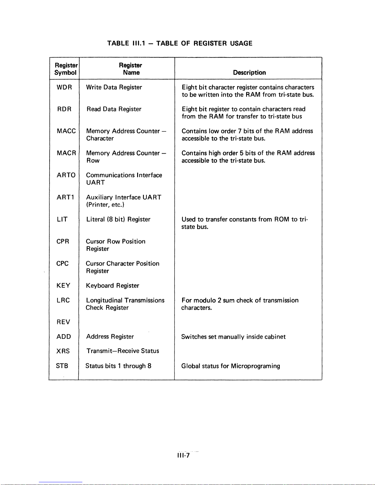
TABLE
111.1 -TABLE
OF REGISTER USAGE
Register Register
Symbol Name Description
WDR
RDR
Write Data Register Eight
Read
Data Register Eight
MACC Memory Address Counter - Contains
Character
bit
character register contains characters
to
be
written
bit
register
from the RAM
low
to
accessible
the tri-state
into
the RAM from tri-state
to
contain characters
for
transfer
order 7 bits
MACR Memory Address Counter - Contains high order 5 bits
ARTO
Row
Communications Interface
accessible
to
the tri-state
UART
ARTl
Auxiliary
Interface
UART
(Printer, etc.)
LIT
Literal (8
bit)
Register
Used
to
transfer constants
state bus.
CPR
Cursor Row Position
Register
CPC
Cursor Character Position
Register
to
tri-state bus
of
the RAM address
bus.
of
the RAM address
bus.
from
ROM
read
to
bus.
tri-
KEY
Keyboard Register
LRC Longitud i nal T ransm issions
Check Register
REV
ADD
XRS
STB
Address Register
Transmit-Receive Status
Status bits 1 through 8
For modulo 2
check
of
transmission
sum
characters.
Switches set manually inside cabinet
for
Global status
Microprograming
111-7
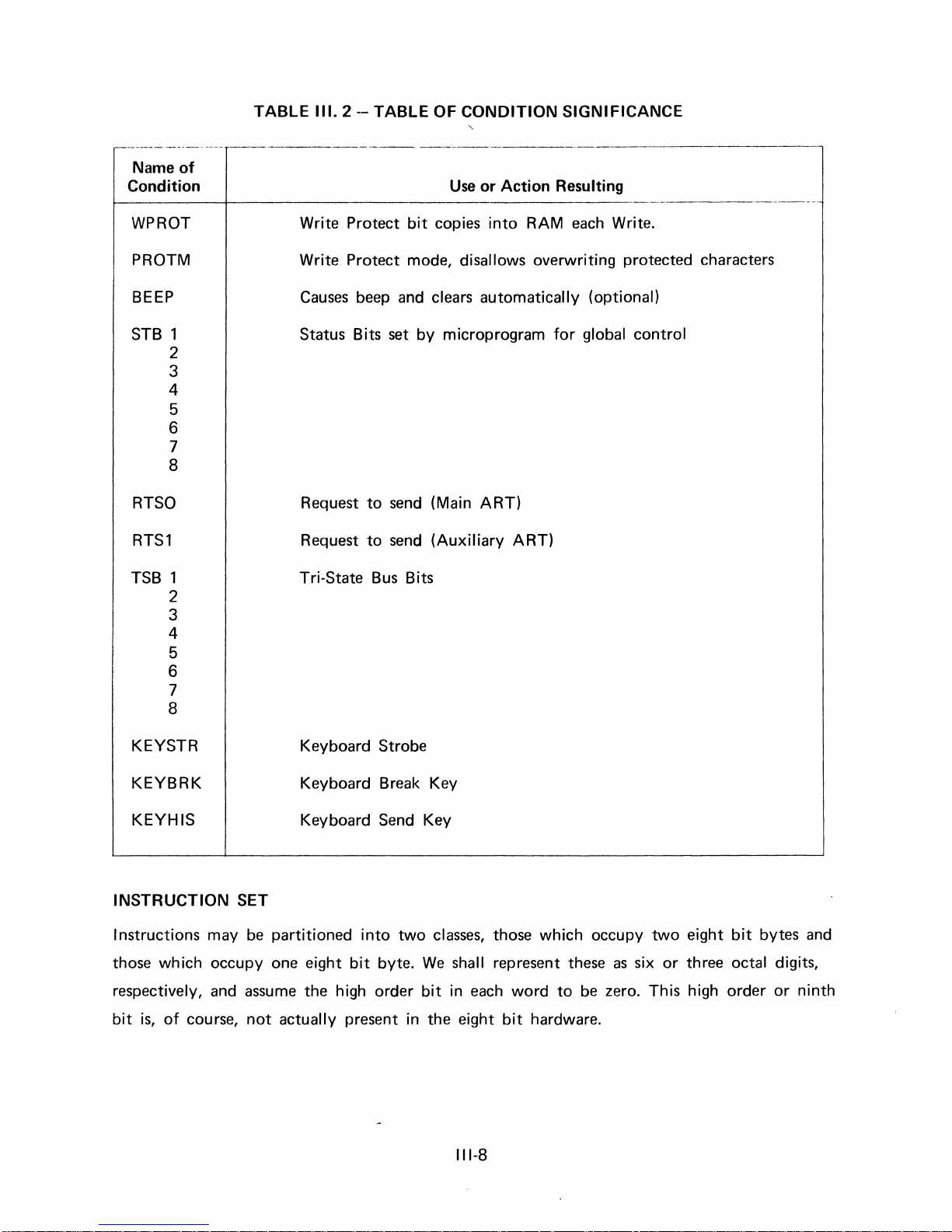
TABLE 111.2 - TABLE
OF
CONDITION SIGNIFICANCE
,-----------
.---
-------------
--------------
Name
of
Condition Use
or
Action Resulting
WPROT
PROTM
BEEP
STB 1
2
3
4
5
6
7
8
RTSO
RTSl
TSB 1
2
3
4
5
6
7
8
KEYSTR
KEYBRK
KEYHIS
INSTRUCTION
SET
Write
Protect
bit
copies
into
RAM
each Write.
Write
Protect
mode, disallows overwriting
protected
characters
Causes beep and clears automatically (optional)
Status
Bits set
by
microprogram
for
global
control
Request
to
send (Main ART)
Request
to
send (Auxiliary ART)
Tri-State Bus Bits
Keyboard
Strobe
Keyboard Break Key
Keyboard
Send Key
I nstructions may be partitioned
into
two
classes,
those
which occupy
two
eight
bit
bytes
and
those which
occupy
one
eight
bit
byte.
We
shall represent these as six
or
three
octal digits,
respectively, and assume
the
high
order
bit
in
each word
to
be zero. This high
order
or
ninth
bit
is,
of
course,
not
actually
present
in
the
eight
bit
hardware.
111-8
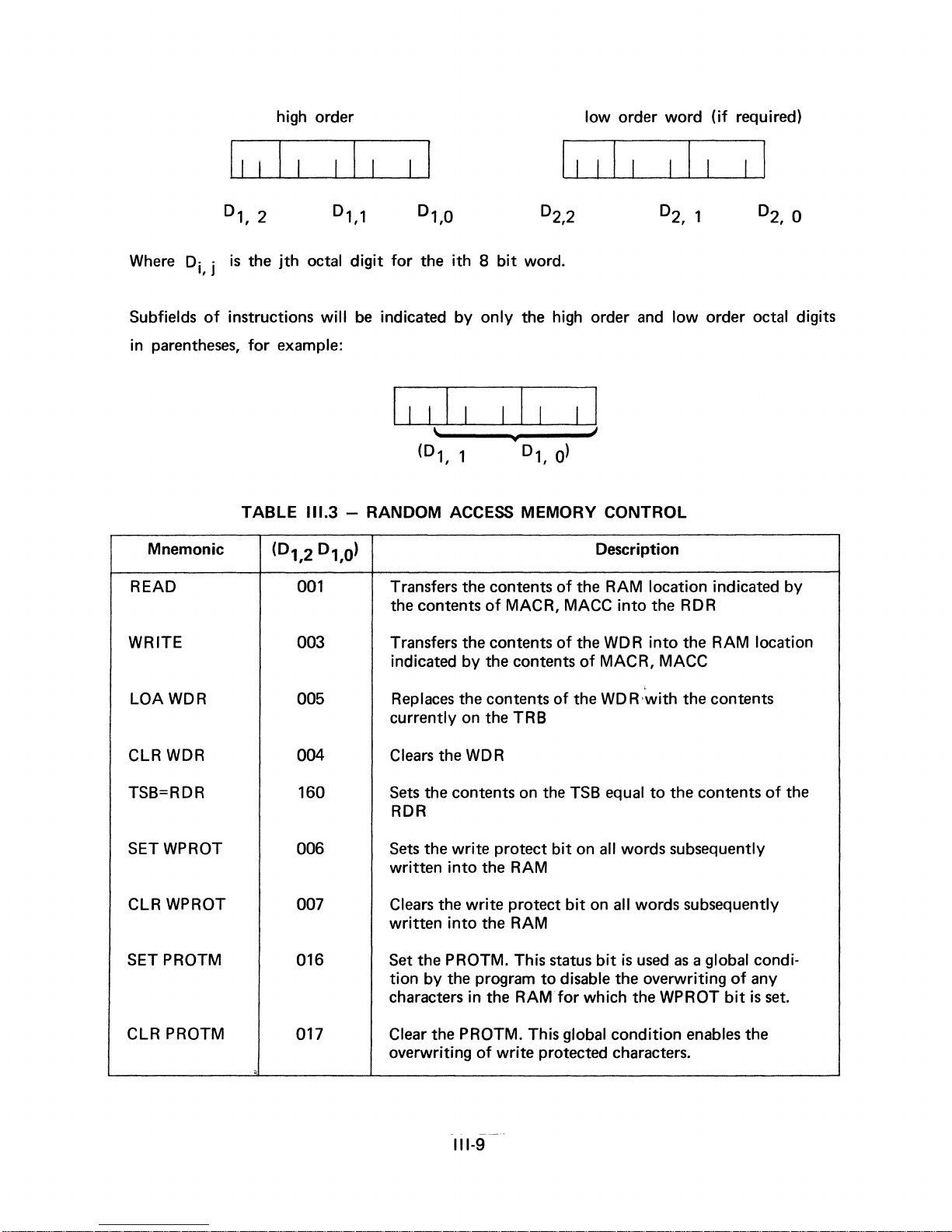
high order
low order word
(if
required)
D1
Where
Subfields
in parentheses,
READ
Di, j
of
Mnemonic
instructions
II
2
,
is
the
for
TABLE
jth
octal
will
example:
111.3
0
,2
(0
1
001
D1
1
,
digit
for
the
be
indicated by
ith 8 bit
word.
only
the high order
and
I I
I
- RANDOM ACCESS MEMORY CONTROL
1
,0)
Transfers the contents
the contents
of
MACR, MACC
Description
of
the RAM location indicated by
into
I I I
low
order octal digits
the RDR
WRITE 003
LOA WDR 005
CLR
WDR
TSB=RDR
SETWPROT 006
WPROT
CLR
SET PROTM 016 Set the PROTM. This status
CLR PROTM
004
160
007
017
'.
Transfers the contents
indicated by the contents
Replaces
currently on the TRB
Clears
Sets
RDR
Sets
written
Clears
written
tion by the program
characters in the RAM
Clear the PROTM. This global condition enables the
overwriting
the contents
the WDR
the contents
the write protect
into
the RAM
the write protect
into
the RAM
of
write protected characters.
of
the WDR
of
of
the
on
the
TSB
bit
on all words subsequently
bit
to
disable the overwriting
for
into
the RAM location
MACR, MACC
WD R with
equal
on
all words subsequently
bit
is
which the WPROT
the contents
to
the contents
used
as
a global condi-
of
bit
of
any
is
set.
the
111-9
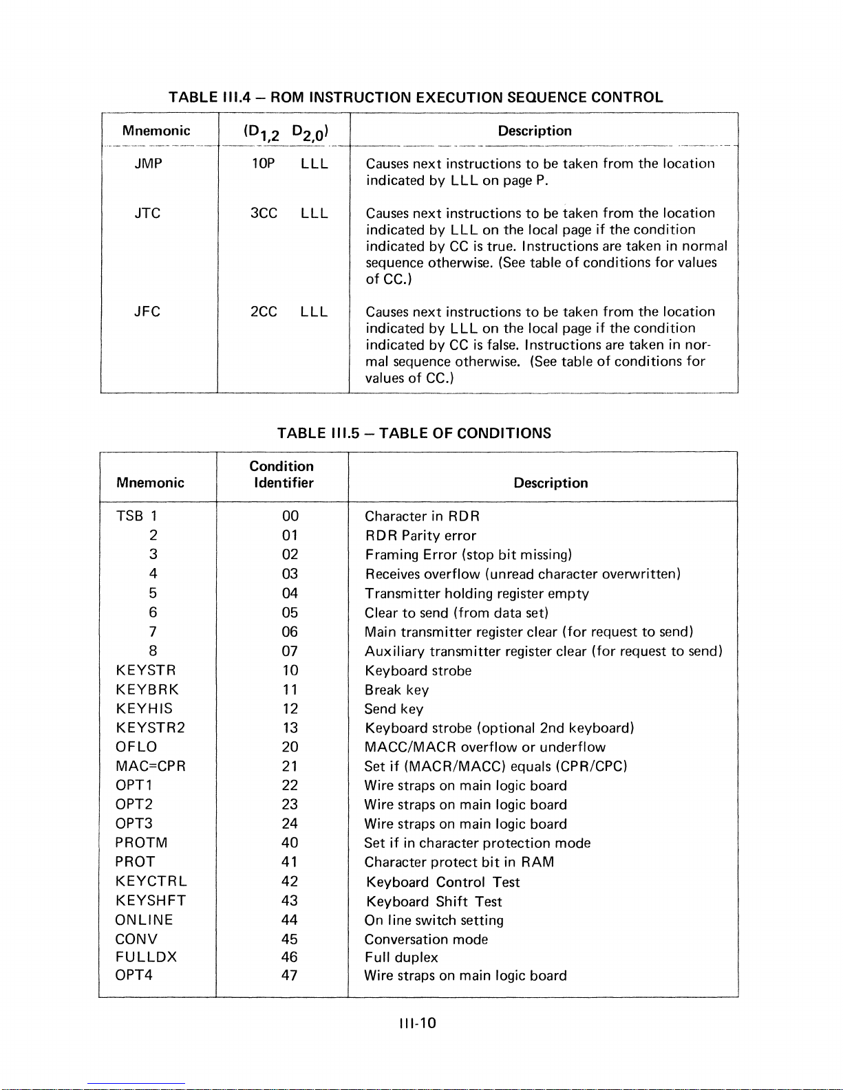
TABLE
111.4
- ROM INSTRUCTION
EXECUTION
SEQUENCE
CONTROL
Mnemonic
JMP
JTC
JFC
Mnemonic
TSB 1
2
3
4
5
6
7
8
KEYSTR
KEYBRK
KEYHIS
KEYSTR2
OFLO
MAC=CPR
OPT1
OPT2
OPT3
PROTM
PROT
KEYCTRL
KEYSHFT
ONLINE
CONV
FULLDX
OPT4
Description
lOP
3CC
2CC
LLL
LLL
LLL
TABLE
Causes
indicated
Causes
indicated
next instructions
by
next
by
indicated by
sequence otherwise.
of
CC.)
Causes
indicated
next
by
indicated by
mal sequence otherwise.
values
111.5 -TABLE
of
CC.)
OF
LLL
on
page
instructions
LLL
on the local
CC
is
true. Instructions
(See
instructions
LLL
on the local
CC
is
false. Instructions
CONDITIONS
to
be
taken from the location
P.
to
be
taken
from
page
if
are
table
of
conditions
to
be
taken
from
page
if
are
(See
table
of
------
Condition
Identifier
00
01
Character in RDR
RDR Parity error
02 Framing Error (stop
Description
bit
missing)
03 Receives overflow (unread character overwritten)
04 Transmitter holding register
Clear
to
send
05
06
07
10
11
12
13
Main transmitter register clear
Auxiliary
Keyboard strobe
Break key
Send key
Keyboard strobe (optional 2nd keyboard)
(from data
transmitter register clear
20 MACC/MACR overflow
Set
if
21
(MACR/MACC) equals (CPR/CPC)
empty
set)
or
underflow
(for
request
(for
22 Wire straps on main logic board
23 Wire straps on main logic board
24
40
41
42
43
44
Wire straps
Set
if
Character protect
on
main logic board
in character protection mode
bit
in RAM
Keyboard Control Test
Keyboard
Shift
Test
On line switch setting
45 Conversation mode
46
47
Full duplex
Wire straps on main logic board
the location
the
condition
taken in normal
for
values
the location
the
condition
taken in nor-
conditions
to
request
for
------
send)
to
send)
111-10
 Loading...