


LEAKWISE
®
Oil on Water Detection & Monitoring
ID-220 SERIES MODEL
SLC-220 Smart Leakwise Controller
&
SLR-220 Smart Leakwise Receiver
for Remote SLC-220’s
Connected to
Any ID-220 Sensor
USER GUIDE
Rev. 2.0 June 2018
With 2
nd
Generation of Main and Outputs Boards
And Firmware Version 4.1 and later

SLC-220 User Guide Rev 2.0 June 2018
2
SLC-220 User Guide Rev 2.0 June 2018
3
Important notes for using a Leakwise system
• Refer to the relevant Sensor User Guide for specific information about
sensor certification, installation and operation.
• Consider the following during operation:
1. Beware of high voltage 100 - 240 ±10% VAC inside the enclosure of the
controller unit! Only qualified personnel may service the system.
2. For a controller in a NEMA 7 or Exd enclosure installed in a Hazardous
Area: The enclosure may be opened for service only when the
surrounding atmosphere is known to be non-explosive! Consult your
local Safety Officer!
3. For a controller in a NEMA 4 (IP65) enclosure: Close the cover properly
to attain the weatherproof properties of the enclosure.
For safety: Install a padlock on each quick release latch of enclosure cover!
4. Ambient operating temperature: -20 to +67°C (-4 to +152°F)
5. Maximum relative humidity inside enclosure: 95%, non-condensing.
6. Maximum altitude: 2000 m.

SLC-220 User Guide Rev 2.0 June 2018
4

SLC-220 User Guide Rev 2.0 June 2018
5
Contents
Important notes for using a Leakwise system ................................................................................................................. 3
Warnings ........................................................................................................................................................................... 7
1 General Description .............................................................................................................................................. 9
2 Installation ............................................................................................................................................................ 13
2.1 Sensor Installation ............................................................................................................................................. 13
2.2 Mounting and Wiring the SLC-220 ................................................................................................................... 13
2.2.1 Connecting the Power Cable ................................................................................................................... 14
2.2.2 Connecting Sensor Cables to SLC-220 .................................................................................................... 15
2.2.3 Connecting the Analog 4-20 mA / 0-5 V Outputs .................................................................................... 17
2.2.4 Connecting the Relay Outputs ................................................................................................................. 19
2.2.5 Adding / Removing Outputs boards, and Selt-Test .................................................................................. 21
2.2.6 Front Panel Status Lights, On-Board Buzzer .......................................................................................... 23
2.2.7 Connecting the RS-485 SCADA Serial Port ............................................................................................ 26
2.2.8 Connecting the RS-485 SLC-220 Interconnect Serial Port ..................................................................... 27
2.2.9 Connecting a PC to RS-232 Serial Port .................................................................................................. 28
2.3 Maximum Cable Length between Sensor and SLC-220 .................................................................................... 29
3 Sensor signals, processing & Calibration ........................................................................................................... 31
Status Description ....................................................................................................................................................... 34
Parameters Description ............................................................................................................................................... 34
4 Using the SLC-Manager Program ...................................................................................................................... 37
4.1 Program Installation ............................................................................................................................................ 37
4.2 Entry Screen ........................................................................................................................................................ 37
4.3 Main Sensors View Screen ................................................................................................................................. 39
4.4 Sensor Settings Screen ........................................................................................................................................ 40
4.5 SLC-220 Settings Screen .................................................................................................................................... 46
5 Using the optional front panel LCD ................................................................................................................... 51
6 Using the optional GSM MODEM ..................................................................................................................... 55
6.1 Configuration Messages ....................................................................................................................................... 57
6.1.1 User Configuration ...................................................................................................................................... 57
6.1.2 Active Sensors .............................................................................................................................................. 57
6.1.3 Sensor Name ................................................................................................................................................ 58
6.1.4 Update Interval ............................................................................................................................................ 58
6.1.5 Sensor Sample Interval ................................................................................................................................ 59
6.2 Calibration Messages ........................................................................................................................................... 60
6.2.1 Set-Points Setting ......................................................................................................................................... 60
6.2.2 Season Setting .............................................................................................................................................. 60
6.2.3 Automatic Calibration .................................................................................................................................. 61
6.2.4 Write Calibration ......................................................................................................................................... 61
6.2.5 Calibration Confirmation............................................................................................................................. 61
6.3 Inquiry Messages ................................................................................................................................................. 62
6.4 Testing the GSM MODEM .................................................................................................................................. 63
7 SLR-220/SGM ...................................................................................................................................................... 64
8 Troubleshooting Guide ........................................................................................................................................ 67
9 Appendix A: Installation in Hazardous Area .................................................................................................... 71
10 Appendix B: Connecting a PC to SLC-220 ........................................................................................................ 71
11 Appendix C: Updating SLC-220 Firmware ....................................................................................................... 75
12 Appendix D: Ferrites for EMC Compatibility................................................................................................... 79
13 Appendix E: SLC-220 Drawings ......................................................................................................................... 82

SLC-220 User Guide Rev 2.0 June 2018
6

SLC-220 User Guide Rev 2.0 June 2018
7
Warnings
English
This is a Class A product. In a domestic environment, this product may cause electromagnetic
interference in which case the user may be required to take adequate measures to correct the
interference.
This is a measurement CAT I device. Do not use in CAT II, CAT III or CAT IV measurement
circuits.
An external switch or circuit breaker (5 Amp) must be installed on the power input line of
the instrument. This switch must disconnect both poles of the supply voltage. It should be
rated, labeled and located appropriately.
INSTALLATION IN HAZARDOUS AREAS:
Do not open the controller enclosure when an explosive gas atmosphere may be present!
Keep enclosure cover tight while circuits are alive.
Seals are required within 3 inches of enclosure threaded holes.
Comply with local norms and regulations during installation and operation.
The power input, sensor input/s and system output connections should be installed by a qualified
electrician.
SLC-220 controller:
For personnel safety and to avoid damage to the instrument:
Disconnect AC/DC supply power before removing the Main board frame.
The On-Off switch is wired in series with the 12VDC internal supply.
Set On-Off switch to Off before connecting / disconnecting any wires!
Leakwise sensors are floating devices.
The installation must allow their free floatation and avoid submergence.
Leakwise sensors are delicate instruments. Handle with care!
Do not drop.
Avoid damages to the cable/s during installation and operation, as this will void the IP67 sealing.
Installation: Follow mechanical and wiring instructions as detailed in the User Guide.
Do not use the system beyond its specifications.
If installed or used in a manner not specified in this User Guide, the protection provided by
the instrument may be impaired.
The sensor is constructed of a plastic material that constitutes a potential electrostatic
hazard. Do not rub! Clean only with a damp cloth.

SLC-220 User Guide Rev 2.0 June 2018
8
Français
Ceci est un produit de classe A. Dans un environnement domestique, ce produit peut provoquer
des interférences électromagnétiques. Dans ce cas l'utilisateur peut être tenu de prendre des
mesures adéquates pour corriger l'interférence.
Ceci est un dispositif de mesure CAT I. Ne pas utiliser dans CAT II, CAT III ou CAT IV circuits de
mesure.
Un interrupteur externe ou disjoncteur (5 Amp) doivent être installés sur la ligne de
l'instrument d'entrée de puissance. Cet interrupteur doit déconnecter les deux pôles de la
tension d'alimentation. Il devrait être classé, étiqueté et situé de manière appropriée.
INSTALLATION DANS DES ZONES DANGEREUSES:
Ne pas ouvrir le boîtier du contrôleur quand une atmosphère explosive de gaz peut être présente!
Gardez le couvercle du boîtier étanche tandis que les circuits sont actifs.
Des joints sont nécessaires dans les 3 pouces de l'enceinte des trous filetés.
Se conformer aux normes et réglementations locales lors de l'installation et de l'exploitation.
Les entrées d'alimentation, entrée du détecteur/s et le système de sortie des connexions doivent
être installés par un électricien qualifié.
Contrôleur SLC-220:
Pour la sécurité du personnel et pour éviter tout dommage à l'instrument:
Déconnectez d'alimentation AC / DC avant de retirer le cadre de la carte principale.
L'interrupteur On-Off est câblé en série avec l'alimentation interne 12VDC.
Réglez l'interrupteur On-Off Off avant de brancher/débrancher tous les fils!
Les détecteur Leakwise sont des dispositifs flottants.
L'installation doit permettre leur flotation libre et éviter toute submersion.
Les détecteur Leakwise sont des instruments délicats a manipuler avec soin!
Ne pas lacher!
Tout dommage créé au câble/s lors de l'installation et de l’utilisation, annulerait automatiquement
l'étanchéité IP67.
Installation: Suivre les instructions mécaniques et le câblage comme détaillé dans le Guide
Utilisateur.
Ne pas utiliser le système au-delà de ses spécifications.
Si installé ou utilisé d'une manière non spécifiée dans ce Guide de l'utilisateur, la
protection fournie par l'instrument peut être altérée.
Le détecteur est constitué d'un matériau plastique qui constitue un danger potentiel
électrostatique. Ne pas frotter! Nettoyer uniquement avec un chiffon humide.
SLC-220 User Guide Rev 2.0 June 2018
9
1 General Description
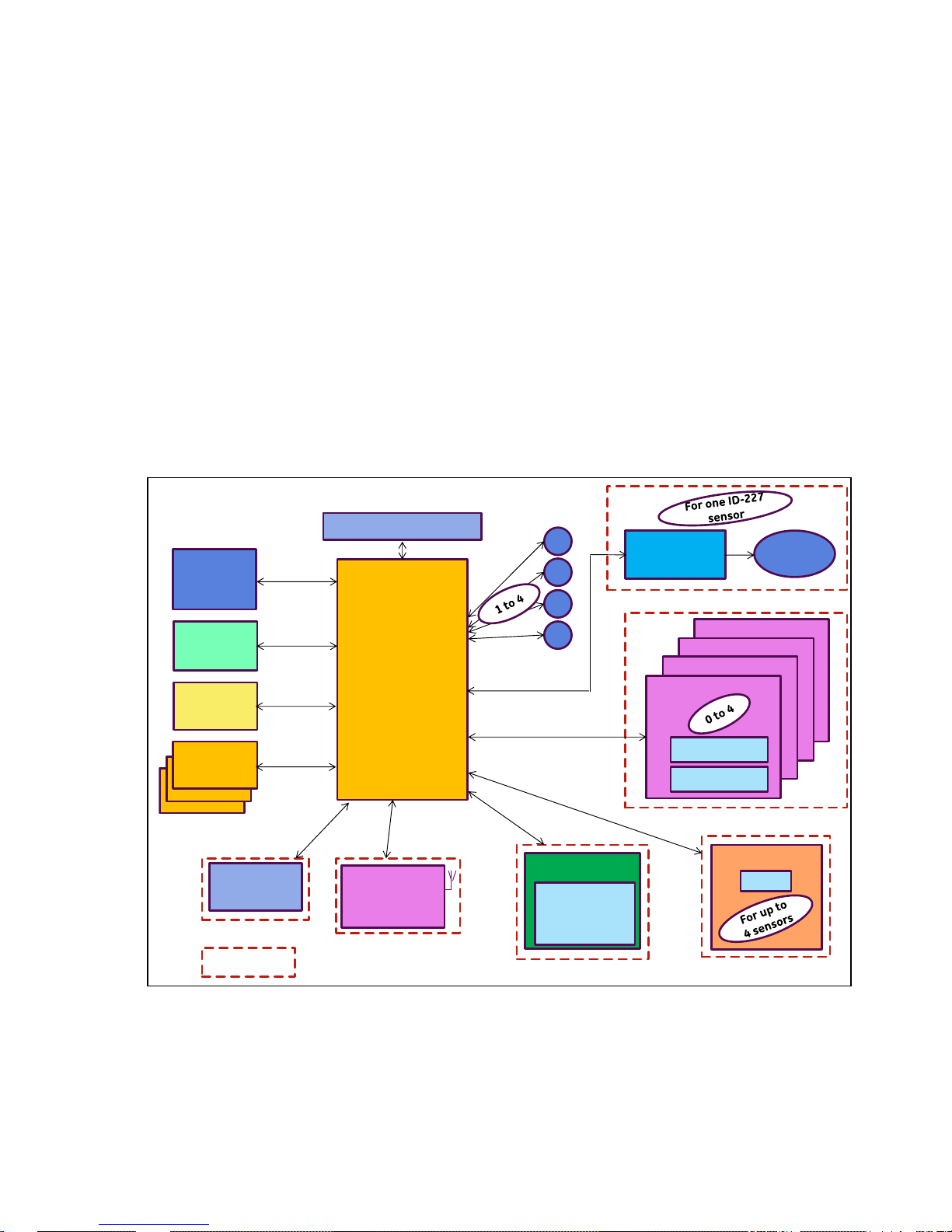
The SLC-220 Smart Leakwise Controller is a digital signal processor that interfaces with Leakwise
ID-220 Series Sensors to report hydrocarbons spill/leak alerts, including layer buildup and
thickness, to users via a wide variety of outputs and communication interfaces for local or remote
reporting. The SLC-220’s modular design and flexible configuration provides solutions for all
specific customer needs. It can be AC or DC line powered or battery powered, and it operates in
wired and/or wireless applications. The SLC-220 supports up to four (4) Leakwise Sensors per
unit. Multiple SLC-220 Controllers can be interconnected to provide a cost-effective, multi-sensor
network (up to 40 sensors).
Block Diagram:
µC Main Board
1
2
3
4
Leakwise
Sensor #
AutoCleaner
Control
Auto
Cleaner
Wireless
Communication:
GSM / Satellite /
Point-to-Point
Indicates
optional feature
Outputs Board # 4
Outputs Board # 3
Outputs Board # 2
Outputs Board # 1
()
1 x 4-20 mA
5 x Relay, SPDT
PC
Connectivity
(Setup &
Calibration)
Power Supply
SCADA
Connectivity
(Modbus)
Status Lights
6 Lights
Display
4.3” Graphic
Color LCD
480*272 Dots +
Touch Panel
Additional
SLC-220
Units (up to 9)
HART
Connectivity
(future)
Hardware
Enhancement
Options
RS-232
RS-485
RS-485
RS-232
RS-232
RS-232

SLC-220 User Guide Rev 2.0 June 2018
10
The SLC-220 is designed for low-power consumption in onshore and offshore applications without
an available power source. Therefore, the operating software extensively uses a “sleep mode”
algorithm that turns off unnecessary hardware. Each monitored sensor is powered on for a short
duration for sampling and decision making, and then turned off. This off interval is userprogrammable. Careful selection and programming of optional features will enable operation for
months from a single battery charge.
All SLC-220 settings and calibrations can be changed locally or remotely through:
• Local LCD & touch screen or RS-232 connection to a PC with the SLC-Manager program
(program supplied with a cable)
• Remote RS-485 connection to the control room through Modbus
• Remote cellular phone messaging if a Cellular modem is installed (SIM card required,
supplied by customer)
The Status of the system is available to the user locally on the LCD or with the SLC-Manager on
the PC, or remotely at the control room through wires connectivity (Modbus) or wireless
connectivity (Cellular / Satellite / Point-to-Point radio).
There are three types of SLC-220:
1. SLC-220/Multi, which supports up to four Leakwise sensors.
2. SLC-220/Basic, which supports up to two Leakwise sensors.
3. SLR-220, which supports up to four local sensor and multiple remote sensors connected to
remote SLC-220 controllers.
SLC-220 User Guide Rev 2.0 June 2018
11
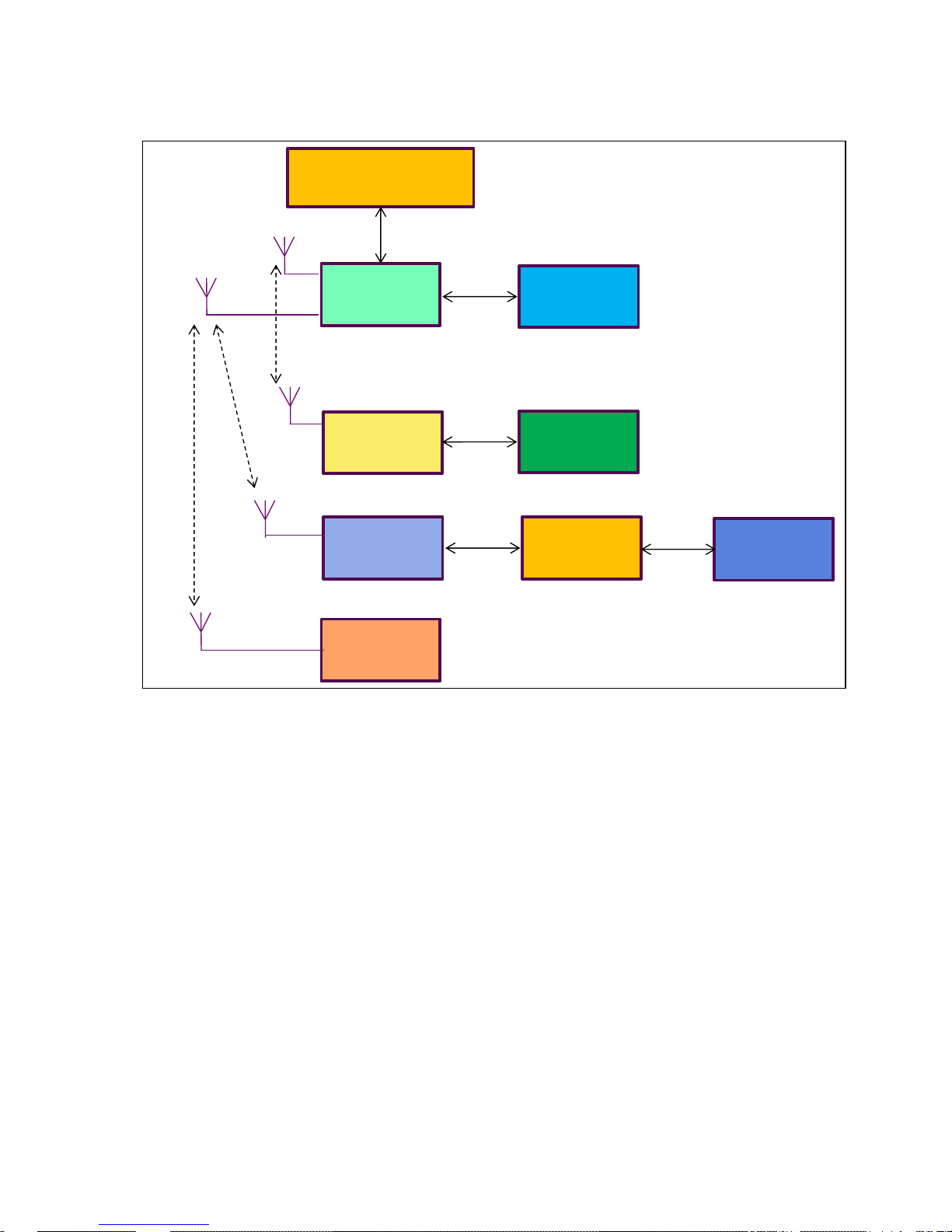
Multiple SLC-220 units as a big system with a single connection to a SCADA:
The main unit is SLC-220 #1, also called SLR-220 (Smart Leakwise Receiver). It collects
information from other SLC-220 units by wired or wireless connectivity.
SCADA (Modbus)
SLC #2
SLC #7
SLR (SLC #1)
SLC #8
SLC #4
SLC #6
SLC #3
SLC #5
RS-485
RS-485
RS-485
RS-485
RS-485
PTP
PTP
GSM
GSM
GSM

SLC-220 User Guide Rev 2.0 June 2018
12

SLC-220 User Guide Rev 2.0 June 2018
13
2 Installation
Installation of the SLC-220 system includes three major steps. First, the sensors and the
SLC-220 unit must be installed in their respective locations. Then, the interconnecting cables
should be wired. Finally, configuration and calibration of the system components should be
performed.
Prior to the calibration procedure, fully install the sensor that has to be calibrated. Instructions and
procedures for system configuration and calibration are described in the next chapters.
NOTE: For EMC compatibility, ferrites should be installed on the power and sensor/s cables.
Refer to Appendix D.
2.1 Sensor Installation
The sensors should be placed and installed in accordance with installation instructions specific to
each type of sensor. Please refer to the appropriate Sensor User Guide.
2.2 Mounting and Wiring the SLC-220
The SLC-220 unit should be mounted in a dry, shaded location, and should have the inside of the
enclosures easily accessible when opening the cover.
For a 100 - 240 VAC system, refer to the following SLC-220 Wiring Diagram: DWGW SLC 003 5.
For a 12 / 24 VDC system, refer to the following SLC-220 Wiring Diagram: DWGW SLC 004 2.
Refer also to mechanical drawings A SLC 0020, A SLC 0021 and A SLC 0030, and when
applicable refer to the NEMA 7 / Exd enclosure drawing/s.
If Safety Barriers are required (hazardous Area installation) refer also to Appendix B in Sensor
User Guide, to drawing DWGV2200012 that shows the summary of ITS certificate No.
Ex01E2023.
The IP65 / NEMA 4 enclosure has a transparent cover with two latches on the right side and
hinges on the left side. After opening the transparent cover there is access to the LCD with touch
screen (if installed), installed on the front panel. Access to the boards and wiring connections is
easy: Lift the front panel with a finger inserted into the hole on the right side of its edge (the
hinges are on the left side).

SLC-220 User Guide Rev 2.0 June 2018
14
2.2.1 Connecting the Power Cable
Make sure that there is no power connected to the cable. Pass the cable through the electrical
conduit that goes from the power source to the SLC-220. Pass the cable through the input gland
on the bottom side of the enclosure.
For 100 - 240 VAC:
Connect the cable to the power-supply terminal block inside the enclosure as follows:
Power Line Contact of Power Supply
Terminal Block
AC PHASE 1 (L)
AC NULL 2 (N)
FRAME GROUND 3 (FG)
NOTE:
Use wires of minimum 18AWG, specified to at least 90°C and 300V.
An external switch or circuit breaker (5 Amp) must be installed on the power input line
of SLC-220. This switch, located near SLC-220, must disconnect both poles of the
supply voltage. It should be rated appropriately and must be marked as the
disconnecting device for SLC-220.
For 12 or 24 VDC:
Connect the cable to the power-supply terminal block inside the enclosure as follows:
Power Line Contact of Power Supply
Terminal Block
+12 or + 24 V 1 (+)
12 V or 24 V RETURN 2 (-)
FRAME GROUND 3 (FG)
Power consumption is 24 Watts maximum.
Note:
1. A Power On-Off switch is installed near the Power Supply terminal block for easier
maintenance when power should be turned off before making wiring changes.
The switch disconnects the 12VDC supply to the boards, not the Mains power!
2. When the SLC-220 is powered up, it goes through a self-test procedure of a few seconds
which turns on all status lights. Only then the sensors are sampled normally and the lights,
relays and 4-20mA outputs are updated to real values.
NOTE for SLC-220/Multi:
If one or more Outputs Boards are provided, they are installed on a separate metallic
mounting plate above the Main board. The mounting plate can be easily removed since
it is fastened by four quick-disconnect nylon studs, giving access to the Main board.
The nylon suds should be used gently to avoid break!
SLC-220 User Guide Rev 2.0 June 2018
15
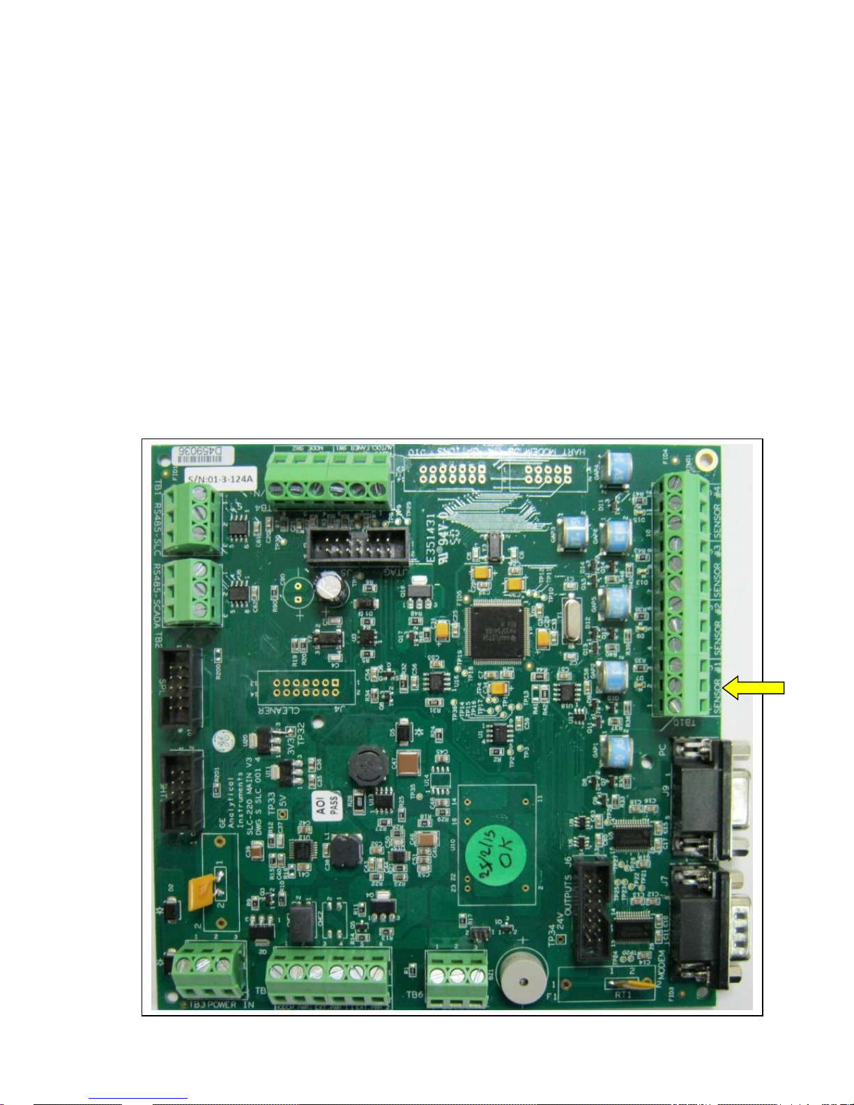
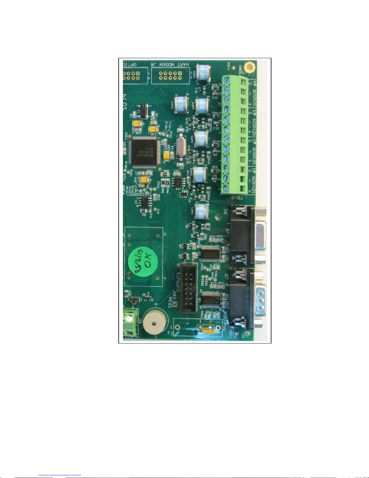
2.2.2 Connecting Sensor Cables to SLC-220
Up to four sensors may be connected to the SLC-220. Each sensor is connected individually. The
sensor wires are passed through the proper sensor cable gland in the external wall of the
enclosure. Then they are connected to the respective contacts in terminal block TB10 (on Main
Board) as follows:
Wire Color TB10 Contact Contact Function
Red or Brown or Black#1 + Sensor +12 VDC (DET+)
Black or Yellow or Black#2 - Sensor GROUND (DET-)
Blue, or Black#3 SIG Sensor SIGNAL (Iout)
Note: For EMC compatibility, a small EMC Filter board is installed as an extension to TB10.
Refer to Appendix D.
Main Board picture:
TB10 is on the right side
SLC-220 User Guide Rev 2.0 June 2018
16
Each sensor input has an indicating red LED on the board to indicate when it is energized. The
LEDs are located on the left side of TB10.
For Hazardous-Area installation, connect the sensor through Zener Safety Barriers which are
installed on an isolated DIN rail inside the enclosure. If the safety barriers are supplied with the
controller, their Safe-Area side is already wired to TB10. Connect the sensors to the HazardousArea side of the safety barriers:
Wire Color Safety Barrier Contact Contact Function
Red or Brown or Black#1 MTL 7715+ point 3 Sensor +12 VDC (DET+)
Black or Yellow or Black#2 MTL 7715+ point 4 Sensor GROUND (DET-)
Blue, or Black#3 MTL 7710+ point 3 Sensor SIGNAL (Iout)
SLC-220 User Guide Rev 2.0 June 2018
17
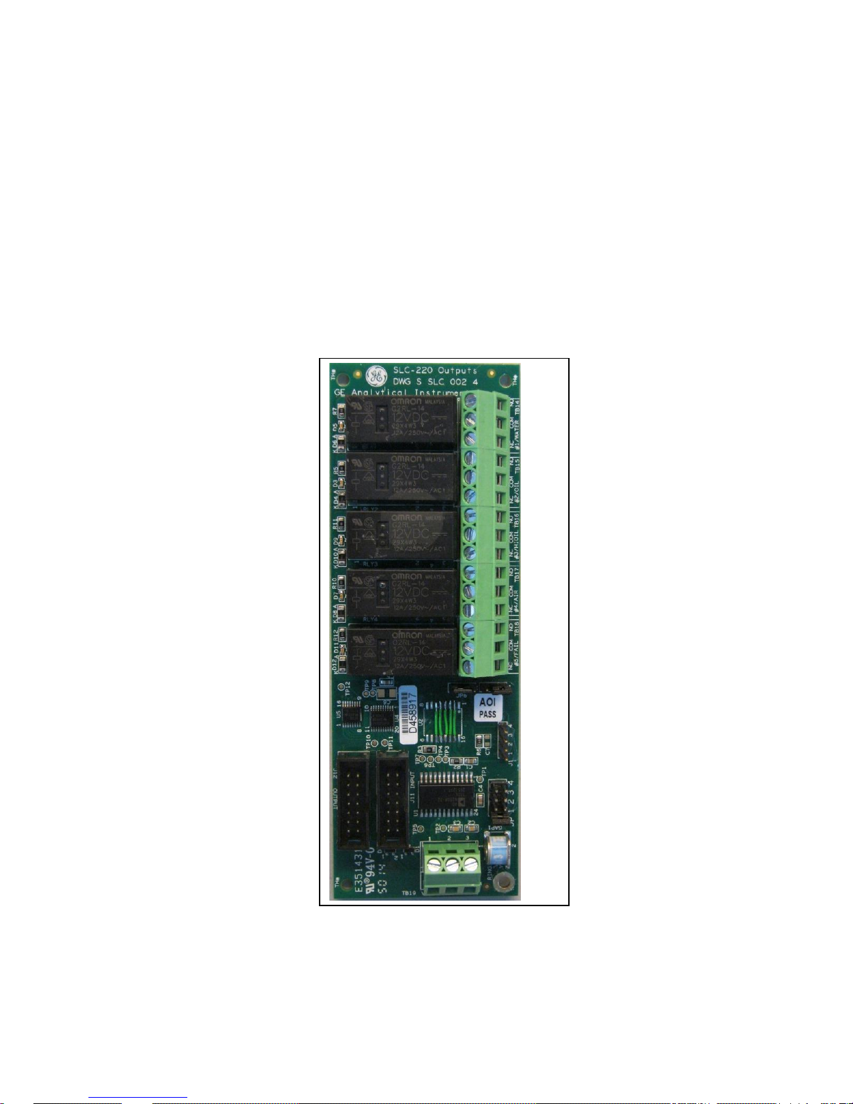
2.2.3 Connecting the Analog 4-20 mA / 0-5 V Outputs
Up to four Outputs boards may be installed in one SLC-220/Multi, up to two in SLC-220/Basic.
The first board on SLC-220/Multi, located rightmost, is associated with sensor #1; the second
board from the right is associated to sensor #2, etc. For SLC-220/Basic, the lower board is
associated with sensor #1; the upper board is associated with sensor #2.
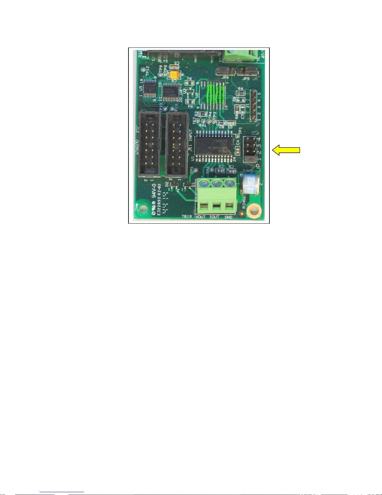
Outputs Board picture:
SLC-220 User Guide Rev 2.0 June 2018
18
If the SLC-220 unit is equipped with Outputs board/s, pass the 4-20mA cable through the proper
cable gland in the external wall of the enclosure. Then connect the two wires to the contacts of
terminal block TB19 as follows:
TB19 Contact Contact Function
Iout 4-20 mA + (Current source, non-isolated)
GND 4-20 mA - (Current return, non-isolated)
If 0-5 V output is required (instead of 4-20 mA), connect each of the two wires to TB19 as follows:
TB19 Contact Contact Function
Vout 0-5 V + (non-isolated)
GND 0-5 V return (non-isolated)
Note: At this point, the current / voltage output is not galvanically isolated.
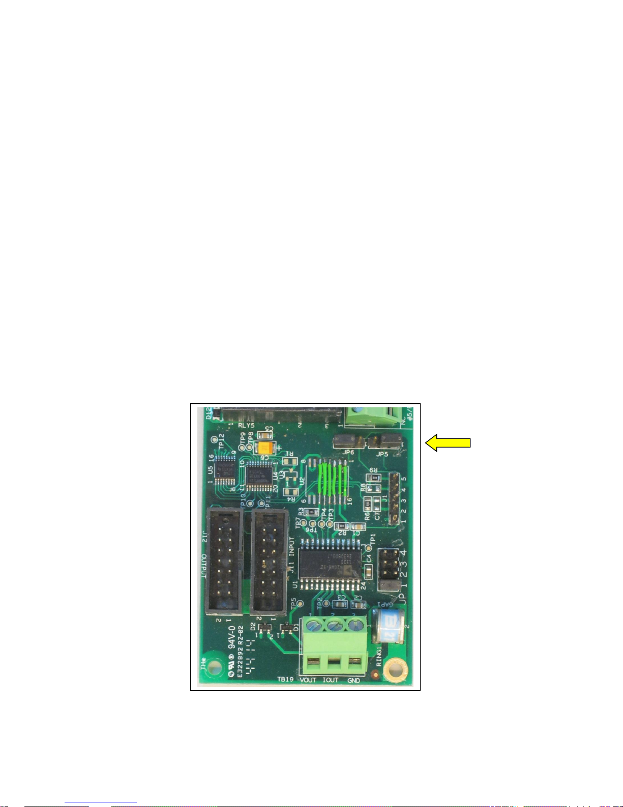
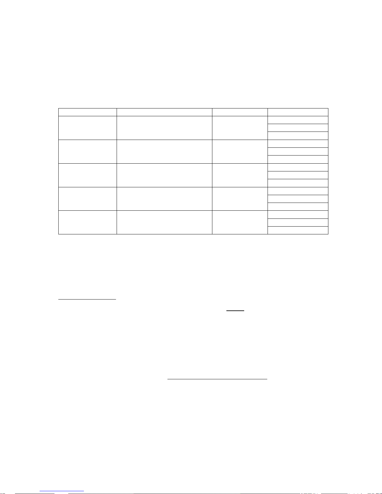
Setting the functionality / range of the output is done by jumpers on the Outputs board:
JP5 position JP6 position Range at TB19
2-3 2-3 0-5 V
1-2 2-3 4-20 mA < This is the default setting
2-3 1-2 0-20 mA
1-2 1-2 0-24 mA
SLC-220 User Guide Rev 2.0 June 2018
19
Arranging the wires:
For SLC-220/Multi, there is one white plastic wire saddle below each Outputs board. Insert the
wires into the saddles and guide them to the left of the enclosure, then down and to the cable
gland.
Note: If there is only one Outputs board and more than one sensor, and the Common functionality
of the Outputs board is selected by setup, then the Analog output will be associated with
sensor#1.
Note: For a disabled sensor associated with an Outputs board, the 4-20mA output will default to
4.33 mA.
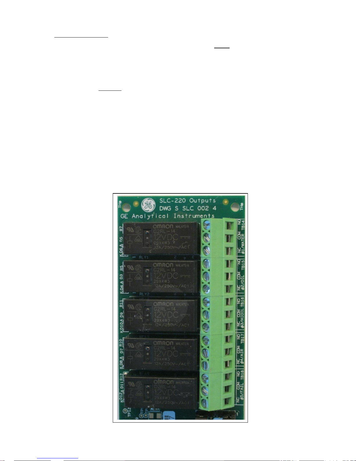
2.2.4 Connecting the Relay Outputs
Up to four Outputs boards may be installed in one SLC-220/Multi. The first board, located
rightmost, is normally associated with sensor #1; the second board from the right is normally
associated to sensor #2, etc. (See note 3 in 2.2.5 for exceptions).
SLC-220 User Guide Rev 2.0 June 2018
20
For SLC-220/Basic, the lower board is associated with sensor #1; the upper board (if installed) is
associated with sensor #2.
Pass the cable through the proper cable gland in the external wall of the enclosure. Then connect
the wires of this cable to the contacts of terminal blocks TB14 till TB18 of the appropriate Outputs
board as follows:
Relay number
Indicated Status
Terminal Block
Contacts
#1
Water or
Oil / High Oil for sensor #1
TB14
NO
COM
NC
#2
Oil or
Oil / High Oil for sensor #2
TB15
NO
COM
NC
#3
High Oil or
Oil / High Oil for sensor #3
TB16
NO
COM
NC
#4
Air or
Oil / High Oil for sensor #4
TB17
NO
COM
NC
#5
Fail or
Common Fail for all sensors
TB18
NO
COM
NC
NO: Normally Opened contact,
COM: Common point,
NC: Normally Closed contact.
Arranging the wires:
In SLC-220/Multi, there is one white plastic wire saddle above every Outputs board. Insert the
wires into the saddles and guide them to the left of the enclosure, then down and to the cable
gland.
Each relay has an indicating LED on the board to indicate when it is energized.
The relays can be set to operate in normal mode or in fail-safe mode. Changing the setting is
done in SLC-220 Settings (chapter 4.5).

SLC-220 User Guide Rev 2.0 June 2018
21
There are two modes to use the relays, depending on the setup:
1. Normal mode: Each sensor activates five relays on the relevant Outputs board. There is
one relay associated with each status: Water, Oil, High Oil, Air and Fail.
2. Common mode: If only one Outputs board is installed, relay #1 will alarm on Oil / High Oil
for sensor #1, relay #2 will alarm on Oil / High Oil for sensor #2, etc., and relay #5 will
alarm on Fail in any of the enabled sensors. This results in individual Oil / High Oil
indication and a common Fail indication.
Changing between the modes is done in SLC-220 Settings (chapter 4.5).
2.2.5 Adding / Removing Outputs boards, and Selt-Test
Up to four Outputs boards may be installed in one SLC-220/Multi. The first board, located
rightmost, is associated with sensor #1; the second board from the right is associated to sensor
#2, etc. The Outputs boards are connected in a series chain to the Main board which sends
updated data to the relays and to the Analog output.
Outputs board #1 is connected by a flat cable from header J11 to header J6 on the Main board.
Outputs board #2 is connected by a flat cable from J11 to J12 on Outputs board #1.
Outputs board #3 is connected by a flat cable from J11 to J12 on Outputs board #2.
Outputs board #4 is connected by a flat cable from J11 to J12 on Outputs board #3.
Note 1: Headers J11 and J12 on each board are actually in parallel; therefore, they may be
interchanged in cases where it is more convenient, for example in SLC-220/Basic.
There are four jumpers on each Outputs board which must be set properly to ensure correct
operation of the outputs. The setting depends on the total number of sensors and Outputs boards,
and their position in the chain:
For SLC-220/Multi, where additional Outputs board/s (up to 4) may be added at any time, the
rightmost Outputs board in the chain will be associated with sensor #1 and will have address #1
(JP1 shorted, JP2, JP3, JP4 disconnected).
Second Output board in the chain will be associated with sensor #2 and will have address #2 (JP2
shorted, JP1, JP3, JP4 disconnected), etc.
SLC-220 User Guide Rev 2.0 June 2018
22
Associating an Outputs board with sensor #1:
Note 2: Update the number of installed Outputs boards in SLC-220 Settings (chapter 4.5).
Note 3: In principle it is not important to associate a certain Outputs board in the chain to a certain
sensor in a rigid order.
Note 4: It is also possible to associate more than one Outputs board to the same sensor! By
doing this, for example, two relays on different Outputs boards will give indications in parallel for
the specific sensor status, and two 4-20mA outputs will give the same information for this sensor.
Note 5: An Outputs board associated to a disabled sensor will not operate: All relays will be deenergized, and all 4-20mA outputs will be set to 4.33 mA.
Outputs board self-test:
1. Power down the controller.
2. Remove the jumper from JP1 / JP2 / JP3 / JP4 of the Outputs board to be tested.
3. Power up the controller.
4. The relays will be energized and de-energized in sequence one after the other.
5. The 4-20mA output will change between 5mA and 10mA when a complete sequence cycle
of the relays in finished.
6. Power off the controller.
7. Insert the jumper back to JP1 / JP2 / JP3 / JP4 (where it was before).
8. Power on. The Outputs board will operate normally.
SLC-220 User Guide Rev 2.0 June 2018
23
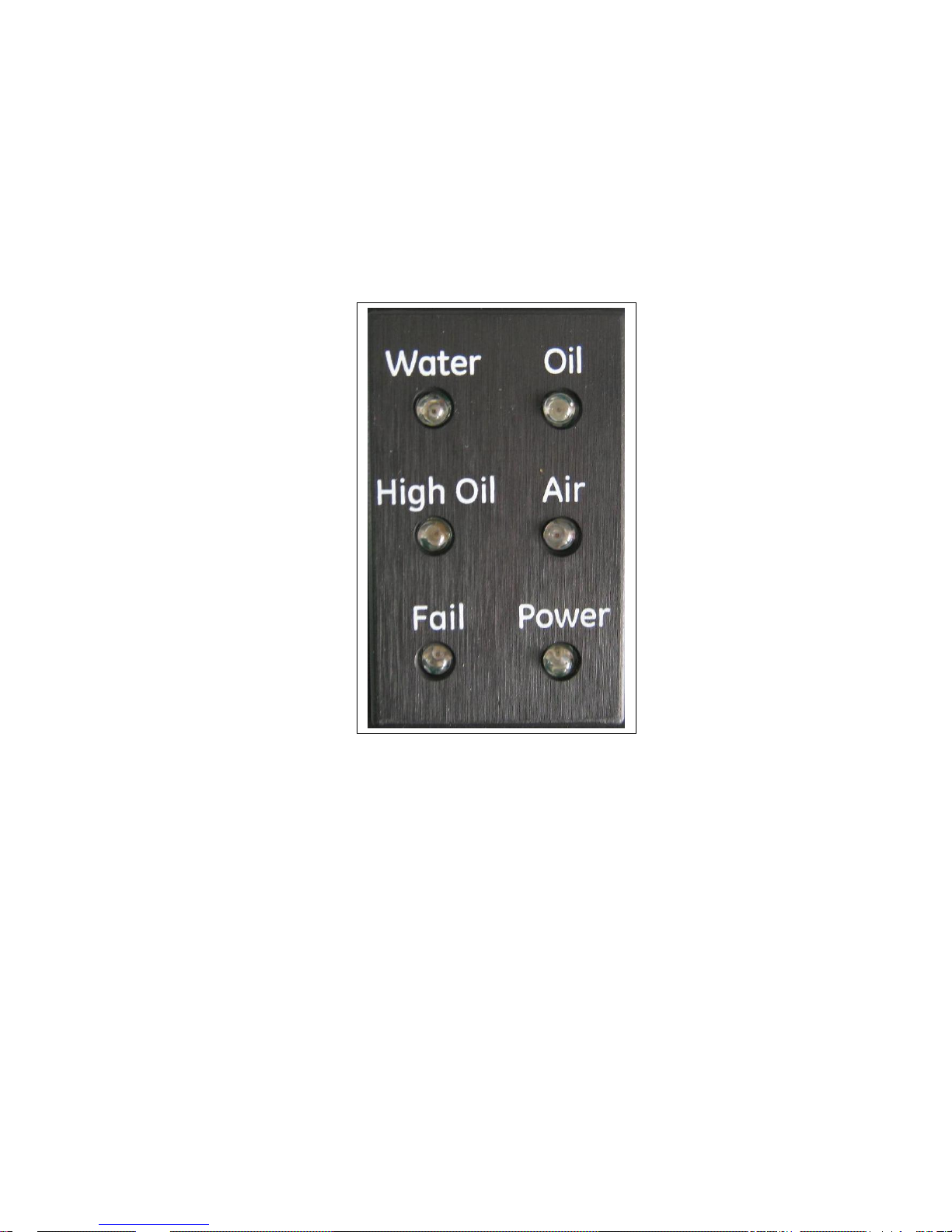
2.2.6 Front Panel Status Lights, On-Board Buzzer
There are six status lights on the front panel.
The Power (green) light indicates operation of the unit.
The other five lights can be used in either of two operating modes:
1. Common mode: Water (green), Oil (red), High Oil (red), Air (yellow) and Fail (yellow)
lights will turn on if any of the enabled sensors (up to four sensors) generates the
appropriate status. Therefore, it is possible that more than one light is turned on.
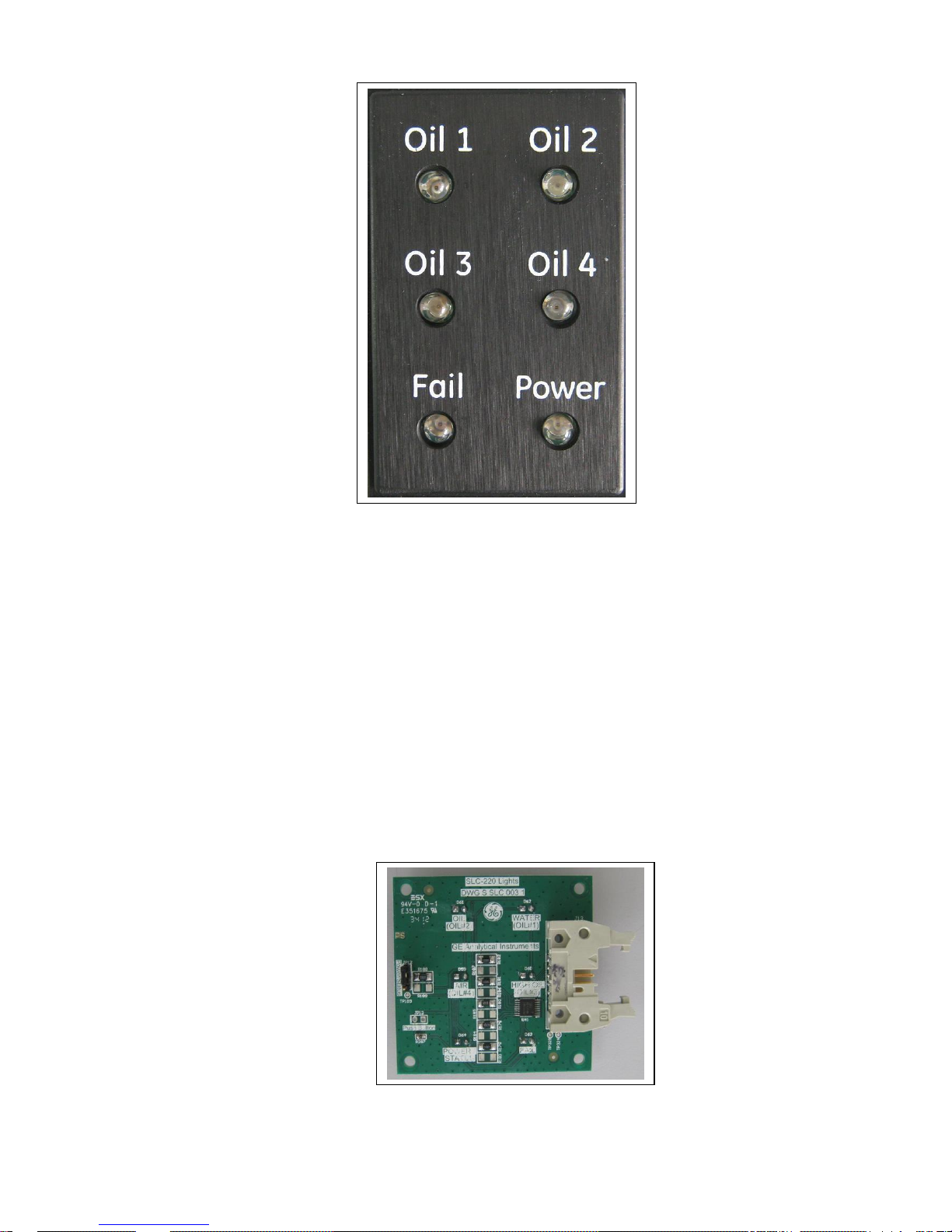
2. Individual mode: Oil 1 (red), Oil 2 (red), Oil 3 (red), Oil 4 (red) and Fail (yellow) lights will
be operated as follows:
• Oil 1 will turn on when sensor #1 generates Oil or High Oil status.
• Oil 2 will turn on when sensor #2 generates Oil or High Oil status.
• Oil 3 will turn on when sensor #3 generates Oil or High Oil status.
• Oil 4 will turn on when sensor #4 generates Oil or High Oil status.
• Fail light is common to all enabled sensors. It will turn on if any of the four sensors
is in Fail status.
Therefore, it is possible that more than one light is turned on.
Note: Status of a disabled sensor will not be reflected in the status lights.
SLC-220 User Guide Rev 2.0 June 2018
24
The system is supplied in Common mode for systems supplied with a single sensor, and in
Individual mode for systems supplied with more than one sensor. In order to change between
modes, if required, do the following:
1. Remove the existing Lights board from the front panel.
2. Remove the aluminum black Lights panel.
3. Install the black Lights panel inverted with the correct legends facing the user.
4. Install another Lights board (DWG S SLC 003 1) that has correct LEDs colors for the
required mode (should be ordered separately). The serial number of a Common mode
board end with a "C", while the serial number of an Individual mode board end with a "I".
5. Make the correct mode setting in SLC-220 Settings (chapter 4.5).
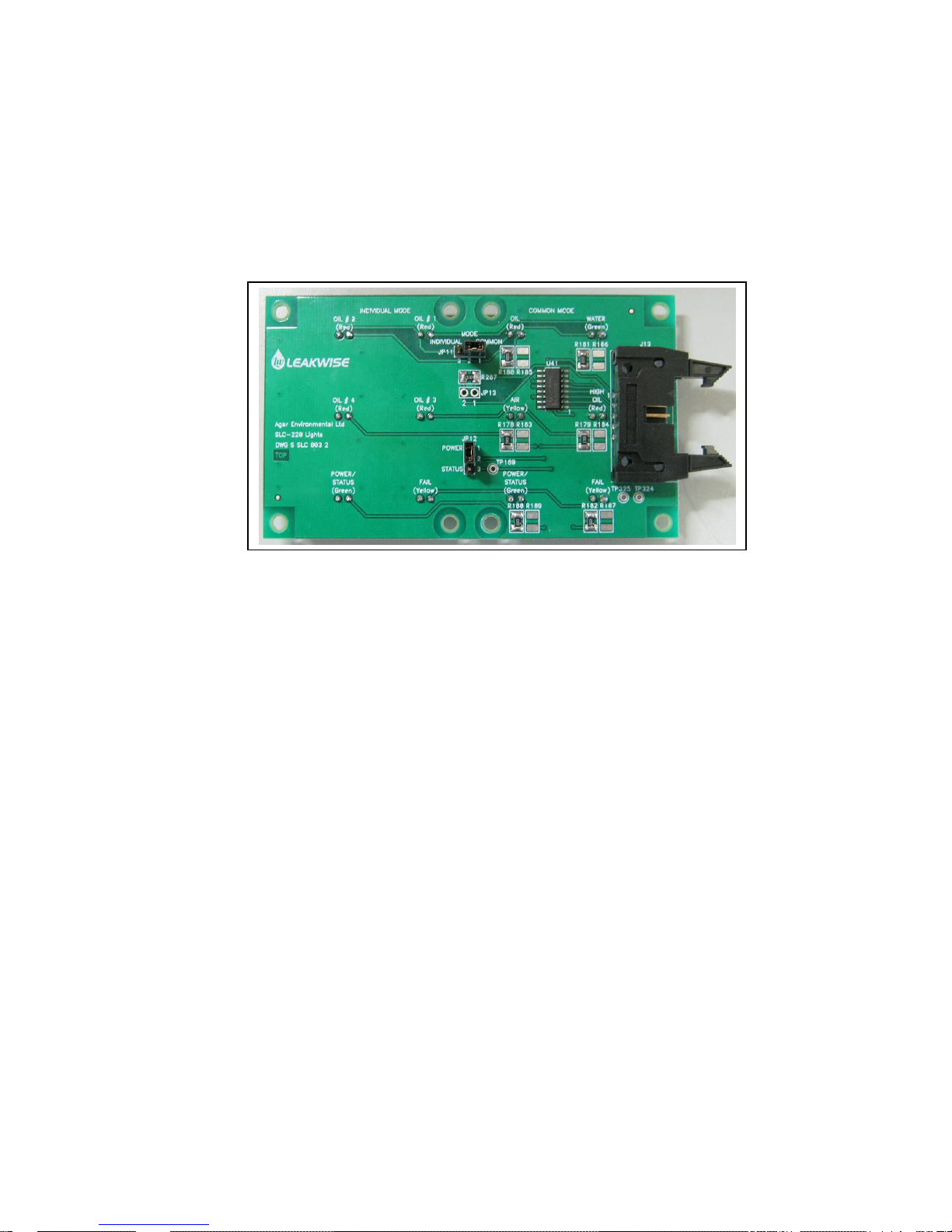
Lights Board picture:
SLC-220 User Guide Rev 2.0 June 2018
25
A new type of Lights board (DWG S SLC 003 2) will be installed during 2018. It supports both
Common and Individual modes, therefore mode change will be very quick and easy. The board
has JP11 MODE jumper to select between the modes.
To use the Common mode, install the board with its’ right side above the black Lights panel.
To use Individual mode, install the board with its’ left side above the black Lights panel.
New Type of Lights Board:
On-Board Buzzer:
Shoring jumper JP1 near the on-board buzzer (and TB6) enables the buzzer.
The buzzer will beep one after a successful parameters update done through the LCD display or
through the SLC-Manager PC program. It will beep multiple times if there are problems in the
parameters, which will then be rejected.
SLC-220 User Guide Rev 2.0 June 2018
26
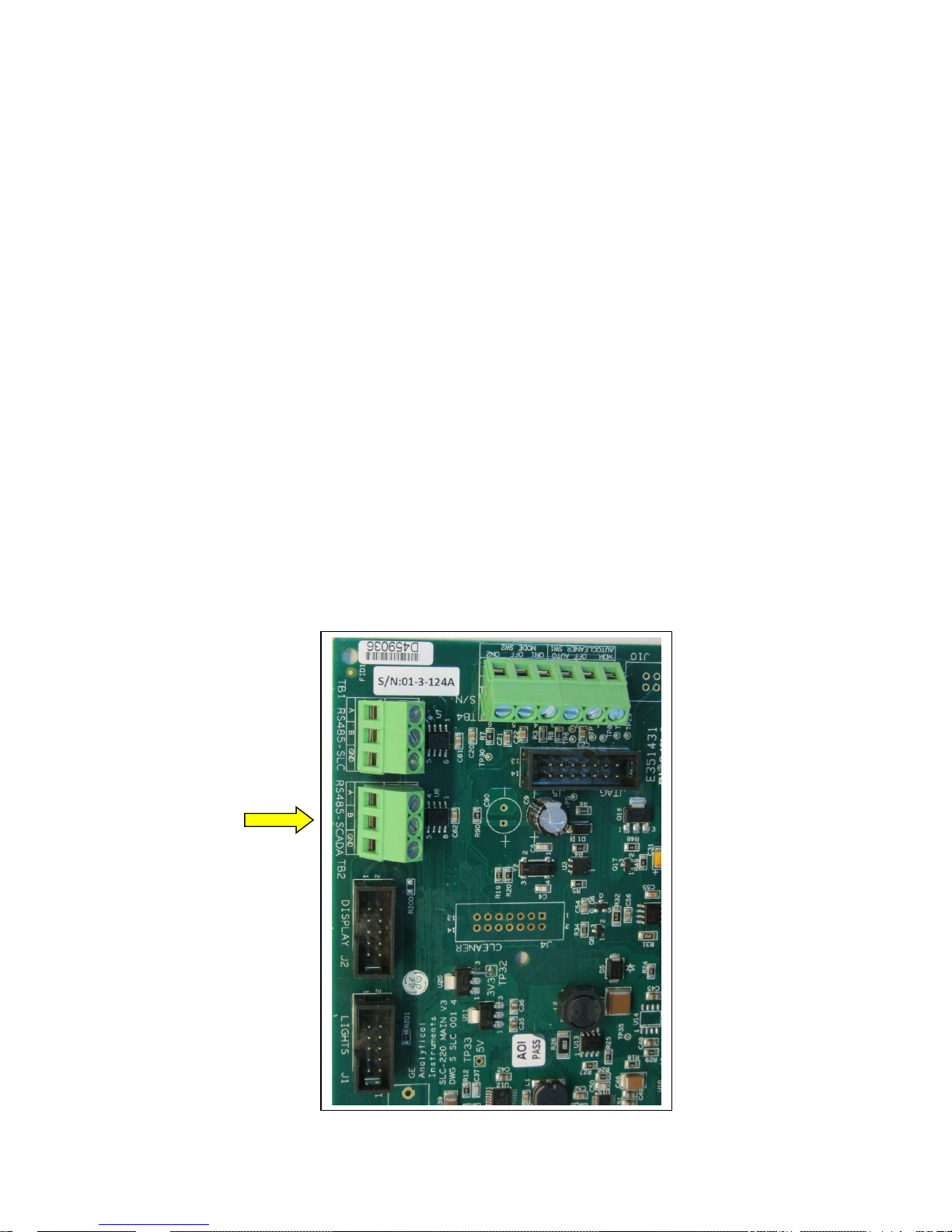
2.2.7 Connecting the RS-485 SCADA Serial Port
This port can be used only for connecting a SCADA or any other unit using Modbus protocol to
the SLC-220 for setup, calibration and status interrogation. The specifics of using the protocol with
SLC-220 are detailed in a separate document.
The port is set to 115,200 Baud as default, 8 data bits, 1 stop bit, no parity and no flow control.
The baud rate can be changed by the SLC-Manager program through the PC serial port.
Pass the cable through the proper gland in the external wall of the enclosure. Then connect the
wires to the contacts of terminal block TB2 on the Main board as follows:
TB2 Contact Contact Function (SLC-220 side)
1 A (non-inverting input)
2 B (inverting input)
3 Ground / shield of Cable
Note: Operating mode is Half Duplex. Full duplex is not supported.
Note: See also the note in 2.2.9.
Main Board top-left corner:

SLC-220 User Guide Rev 2.0 June 2018
27
2.2.8 Connecting the RS-485 SLC-220 Interconnect Serial Port
This port can be used only for future connection of a SLC-220 unit to a network of multiple SLC220 units and a SLR-220. No other device should be connected to this port.
Pass the cable through the proper gland in the external wall of the enclosure. Then connect the
wires to the contacts of terminal block TB1 on the Main board as follows:
TB1 Contact Contact Function (SLC-220 side)
1 A (non-inverting input)
2 B (inverting input)
3 Ground / shield of Cable
Note 1: Operating mode is Half Duplex. Full duplex is not supported.
Note 2: Functionality of this port is not implemented yet.

SLC-220 User Guide Rev 2.0 June 2018
28
2.2.9 Connecting a PC to RS-232 Serial Port
A PC can be connected to the SLC-220 for setup, calibration and monitoring the sensors when
required. The PC should have the SLC-Manager program installed to do this.
A RS-232 cable is supplied: Male to female, non-crossed Rx & Tx. Connect the 9-pin male DSubminiature connector to connector J9 on the Main board, as follows:
J9 Contact Contact Function (SLC-220 side)
2 RxD (Data input to SLC-220)
3 TxD (Data output from SLC)
4 DTR (Input, Data Terminal Ready from PC)
5 GND (and shield of RS-232 Cable)
Connection of PC DTR to pin 4 is essential to enable automatic detection of a device connected to
this port.
For a PC without a RS-232 connector, a RS-232 to USB adaptor is also supplied.
For IP65 / NEMA 4 enclosure of SLC-200/Multi: Connect the PC to an extension connector
located at the top-left of the opened enclosure, and marked "PC".
For IP65 / NEMA 4 enclosure of SLC-200/Basic: Connect the PC to an extension connector
located at the right of the opened enclosure, and marked "PC".
For Exd / NEMA 7 enclosure: There is a "PC" connector located under the glass window. This
enables easy connection of a PC without the need to open the screws of the enclosure.
The communication through this port is in Modbus protocol with a fixed address 1. Therefore, a
SCADA can be connected to the RS-232 port if required.
The port is set to a fixed 115,200 Baud, 8 data bits, 1 stop bit, no parity, and no flow control.
Note: The PC and the SCADA share the same serial port on the SLC-220 Main board. When a
PC or any other terminal is connected to the RS-232 port, the RS-485 SCADA port is disabled
within 10 seconds after the SCADA confirms this event. This is required since the SLC-220 acts
as a slave device, and can handle only one master device at a time: PC or SCADA.

SLC-220 User Guide Rev 2.0 June 2018
29
2.3 Maximum Cable Length between Sensor and SLC-220
The integral cable supplied with the sensor can be extended with another cable after a connection
inside an IP65 junction box.
ID-221 and all ID-223 sensors:
1. For Gas Group IIC hazardous area (Hydrogen):
150 meters maximum if 20 AWG wires (or thicker wires) are used.
1100 meters maximum if 22 AWG wires are used.
2. For Gas Groups IIA or IIB hazardous area (Ethylene and Propane):
1800 meters maximum if 20 AWG wires (or thicker wires) are used.
1100 meters maximum if 22 AWG wires are used.
3. For non-hazardous area:
1800 meters maximum if 20 AWG wires (or thicker wires) are used.
ID-225 sensors:
1. For Gas Group IIC hazardous area (Hydrogen):
150 meters maximum if 20 AWG wires (or thicker wires) are used.
550 meters maximum if 22 AWG wires are used.
2. For Gas Groups IIA or IIB hazardous area (Ethylene and Propane):
1300 meters maximum if 18 AWG wires (or thicker wires) are used.
900 meters maximum if 20 AWG wires are used.
3. For non-hazardous area:
1300 meters maximum if 18 AWG wires (or thicker wires) are used.
ID-227 sensors:
1. For Gas Group IIC hazardous area (Hydrogen):
150 meters maximum if 20 AWG wires (or thicker wires) are used.
1000 meters maximum if 22 AWG wires are used.
2. For Gas Groups IIA or IIB hazardous area (Ethylene and Propane):
1600 meters maximum if 20 AWG wires (or thicker wires) are used.
1000 meters maximum if 22 AWG wires are used.
3. For non-hazardous area:
1800 meters maximum if 20 AWG wires (or thicker wires) are used.
The above maximum cable lengths refer to connecting the sensor to Safety Barriers. Safety
Barriers are usually installed close to the signal processor in a safe area. A safe area may be an
Explosion Proof enclosure installed in a hazardous area. The Safety Barriers may be installed in a
longer distance from the signal processor, and the connecting cable between them and signal
processor should have 16 AWG wires (or thicker).

SLC-220 User Guide Rev 2.0 June 2018
30
If the installation is not in hazardous area (safety barriers are not used):
The cable should be a simple cable used for power purposes, for example 3 times 1 or 1.5 mm².
Do not use a communication cable with twisted wires or a coaxial type.
If the installation is in hazardous area (safety barriers are used):
Use a cable of 3 conductors (gauge as described above), non-twisted inside outer jacket
(communication cables are not good).
The jacket should withstand 500 V RMS.
The capacitance between each two wires should not exceed 200 pF/meter.
The inductance of each wire should not exceed 0.7 uH/meter.
Select such a cable from a catalog or test its capacitance and inductance.
A shielded cable is not required in most cases.
Zener Safety Barriers for installation in hazardous area:
Note: MTL 715+ and 710+ are obsolete. Use MTL 7715+ and 7710+.

SLC-220 User Guide Rev 2.0 June 2018
31
3 Sensor signals, processing & Calibration
Each Leakwise sensor has a cable with three wires named: DET+, DET-, DET Sig.
DET+ : +12VDC supply in reference to DET-. Supplied current is the sum of the currents through
the other two wires.
DET- : Power and signal ground. Returning current between 6 to 9mA, no matter if the sensor is in
air or in water.
DET Sig. : Sensors' current output signal, value depends on sensor model and on liquid condition
around the sensor, typically as follows:
Typical signal values are:
ID-221: In Air: 0.65 to 0.85 mA
In clean Water: 1.00 to 1.30 mA
ID-223 (all models): In Air: 0.90 to 1.10 mA if the sensor is 20 mm or more above bottom flange.
In Air: 0.65 mA when the sensor is resting on bottom flange.
In Oil layer of 30 mm or more: 0.97 to 1.10 mA
In clean Water: 1.60 to 1.90 mA
ID-225/100: In Air: 1.00 mA.
In Oil layer of 110 mm or more: 1.20 mA
In clean Water: 3.20 to 3.40 mA
ID-225/200: In Air: 1.10 mA.
In Oil layer of 230 mm or more: 1.44 mA
In clean Water: 4.30 to 4.50 mA
ID-227: In Air: 0.80 to 1.00 mA.
In clean Water: 1.35 to 1.80 mA
The signal gets lower below Water signal as oil layer increases.

SLC-220 User Guide Rev 2.0 June 2018
32
The following diagram reflects the relation between sensor output signal, set-points, calibration
points and possible status messages that are shown on the front panel Lights, on optional LCD
display, on the PC screen, and the information sent to the SCADA.
The shown µA signal values are typical to ID-223 sensors. Signal decrease means a thicker oil
layer.
Set Points & Calibration Points (µA) Sensor Status
1700µA
1600µA
1570µA
1480µA
900µA
800µA
600µA
0µA
Water Cal. + 100
Water Calibration (Cal. Point = 1600)
Over Range Delta (Value = 100)
Oil Delta (Value = 30)
High Oil Delta (Value = 120)
Water Cal. - 120
Water Cal. - 30
Air Cal. + 100
Air Delta (Value = 100)
Air Calibration (Cal. Point = 800)
Under Range Set Point (Set Point = 600)

SLC-220 User Guide Rev 2.0 June 2018
33
The SLC-220 processor is responsible for status/warning decision-making based on comparing
the existing sensor signal to the calibration and set point parameters that were programmed by
the user.
For example, “Oil Alarm” will be determined when sensor’s signal is more than Water Calibration
minus High Oil Delta set point, and also less than Water Calibration minus Oil Delta set point.
Only one status is possible at a given time.
Calibration parameters Water Calibration and Air Calibration are the basic reference for every
decision-making. These two parameters should be entered once after seeing the measured
sensor signal when the sensor is dry (Air Calibration) and when the sensor is floating in clean site
water (Water Calibration).
All calibration parameters are positive numbers, in µA.
The following set points are in reference to Water Calibration:
• Over range Delta: Sensor signal above Water Calibration + Over Range Delta is
abnormal and indicates that the sensor either went under water or failed.
• Oil Delta: Sensor signal below Water Calibration – Oil Delta means oil detection. This is
the first oil alarm setting, for relatively thin oil layer detection.
• High oil Delta: Sensor signal below Water Calibration – High Oil Delta means high-oil
detection. This is the second oil alarm setting, for relatively thick oil layer detection.
Air Delta is in reference to Air Calibration. This parameter ensures that when the sensor is not
floating on water or on oil, the indicated status will be AIR even if the sensor is not 100% dry.
Under Range Set Point is an absolute parameter. It defines a minimum signal which is normally
expected from the sensor. If sensor signal is lower than this value, it the sensor failed.
In addition to the above parameters, there is a Hysteresis parameter that influences each
comparison of sensor’s signal to the other parameters and calibration points. The default value is
5 µA, and it adds a hysteresis of ±5 µA around each crossing point between two adjacent status
decisions.

SLC-220 User Guide Rev 2.0 June 2018
34
Status Description
1. WATER: The most normal indication when no oil is detected, and the sump is not dry.
2. OIL alarm: Small oil layer was detected.
3. HIGH OIL alarm: A thick oil layer was detected, thicker than Oil 1 Alarm.
4. AIR: The sensor is out of water or oil (the sump is dry).
5. SIGNAL TOO HIGH: Indicated a possible sensor failure or an improper floatation (too
deep or submerged).
6. SIGNAL TOO LOW: Indicated a possible sensor failure.
The Lights on the front panel will show FAIL status for any fail indication. The details about the
nature of the failure can be seen through the PC, Modbus, LCD or wireless communication,
whatever option implemented.
Parameters Description
•
Water Calibration
A value (in μA) that is equal to sensor output when floating properly in clean water. If the
measured signal is more than Water Calibration - Oil Delta + Hysteresis, then the status is
WATER.
•
Oil Delta
A value (in μA) below Water Calibration.
If sensor's signal is less than Water Calibration - Oil Delta - Hysteresis then the status is OIL
alarm.
•
High Oil Delta
A value (in μA) below Water Calibration.
If sensor's signal is less than Water Calibration - High Oil Delta - Hysteresis then the status is
HIGH OIL alarm.
•
Air Calibration
A value (in μA) that is equal to sensor output in Air, without any liquid around.
Note: For ID-223, this is the value when the sensor is held by a non-metallic spacer at least
2 cm above the bottom flange of the cage.
•
Air Delta
A value (in μA) above Air Calibration. It is used for ensuring Air status even if the sensor is a bit
wet or doesn’t sit correctly on the bottom flange.
If measured sensor's signal is less than Air Calibration + Air Delta – Hysteresis then the status is
AIR.

SLC-220 User Guide Rev 2.0 June 2018
35
•
Hysteresis for all Thresholds
This is a value (in μA) above and below each of the crossing points between adjacent
status indications. This value introduces a Hysteresis window around each crossing point
to prevent bouncing between two status changes and unstable operation of relay outputs.
This value if 5 μA as default, but can be changed (see SLC-220 Advanced Settings).
•
Over range Delta
This is a value (in μA) above Water Calibration. If measured sensor's signal is higher than
Water Calibration + Over Range Delta + Hysteresis, the status will be FAIL:
SIGNAL TOO HIGH.
•
Under Range Set Point
This is an absolute value (in μA) that indicates an abnormal low sensor signal value limit. If
measured sensor's signal is lower than Under Range Set Point - Hysteresis, the status will
be FAIL: SIGNAL TOO LOW.
Note:
The SLC-220 is factory set and calibrated according to the supplied sensors or to typical values of
the supplied sensors. The minimum settings that should be done after installation are: Water
calibration, Air calibration, Oil Delta and High Oil Delta.
NOTE:
Refer to sensor User Guide for specific notes related to floatation and calibration.
Important Note:
All the following calibration rules must always be valid to enable the system to perform
correctly:
• Water Calibration > Air Calibration
• Oil Delta < High Oil Delta
• (Water Calibration - High Oil Delta - Hysteresis) >
(Air Calibration + Air Delta + Hysteresis + 10 μA)
• Under Range Set Point < Air Calibration
The SLC-220 will give a feedback if the rules are violated and will reject such wrong settings.

SLC-220 User Guide Rev 2.0 June 2018
36

SLC-220 User Guide Rev 2.0 June 2018
37
4 Using the SLC-Manager Program
4.1 Program Installation
The SLC-Manager Program is supplied on a CD. It will work on MS Windows XP, 7 and 10
operating systems. A RS-232 cable is also supplied. The PC needs a RS-232 serial port or a USB
port with USB to RS-232 adaptor.
Simple installation of the SLC-Manager Program is required from the Installation folder in the CD;
run setup.exe. SLC-Manager (and SLC-Manager OFFLINE for versions before 2.0.0.1) will be
created in the Start menu and on the desktop. Use SLC-Manager to start the program when a
SLC-220 unit is connected to the PC. SLC-Manager OFFLINE can be used to work on settings
without a connection to the SLC-220 unit.
4.2 Entry Screen

SLC-220 User Guide Rev 2.0 June 2018
38
Unit Type:
Currently it is SLC-220. In the future SLR-220 central controller will be available for selection.
About/Info button:
Optional access to documentation.
Offline Mode (Not Connected) check box:
For version 2.0.0.1 and later. If the Check Box is marked, the program enables loading a
parameters file from PC, editing the parameters and then saving them to PC. No communication
with the SLC-220 controller can be done.
Communication Settings button:
Selecting and setting of the PC serial port. Default setting is 115,200 baud, 8 data bits, no parity,
one stop bit. If the SLC-Manager doesn’t connect to the SLC-220, press the Advanced button
and then Save.
Optionally, MODBUS registers access is possible for the integration phase with a SCADA.
Change User Authorization Level button:
There are three available system access levels:
View Level:
Default entry level when the program is launched. It enables only viewing the settings
without the ability to change them.
Technician Level:
Allowed to view all parameters and can also change most practical parameters.
Initial password is 1234. It can be changed in the SLC-220 Settings screen.
Administrator Level:
Allowed to view all parameters and can also change all parameters (including advanced).
Initial password is 5678. It can be changed in the SLC-220 Settings - advanced screen.
If the correct Password is not accepted by the SLC-220, reset both SLC-220 and SLC-Manager.
The current active User Level is displayed at the bottom of the screen, below the Date/Time.
Connected / Disconnected indication:
Indicates if the SLC-220 is communicating with SLC-Manager. A Green dot indicated Connected;
a Red dot indicates Disconnected.
SLC-220 Main board serial number: Displayed below the Connected/Disconnected indication.
SLC-220 Main board firmware version: Displayed below the serial number and above
Date/Time.
Date and Time: Taken from the controller. It will be updated to PC time during the next “Save to
SLC” operation – see section 4.5.
Enter button: Enter to the Main Sensors View screen.
Exit button: Exit SLC-Manager.

SLC-220 User Guide Rev 2.0 June 2018
39
4.3 Main Sensors View Screen
This screen shows the current status of all four sensors.
For each sensor the data includes:
Sensor / Installation site name,
Status,
Raw sensor signal in µA
A color bar graph that indicates the signal visually within the calibration range.
Sensor 1 / Sensor 2 / Sensor 3 / Sensor 4 buttons:
Pressing one of these buttons continues to a detailed specific Sensor Settings screen.
Entry Screen button: Return to the Entry Screen.
SLC-220 Menu button: Continue to the SLC-220 Settings screen.
The lower area of the screen is for SLC-220 special status / error Messages.

SLC-220 User Guide Rev 2.0 June 2018
40
4.4 Sensor Settings Screen
This screen enables viewing and changing the parameters of a specific sensor, and also view the
status in the corresponding Outputs board.
The number of the selected sensor is shown on the top-left.
The default view is View Parameters as shown on next page.

SLC-220 User Guide Rev 2.0 June 2018
41
The parameters can be changed after pressing the Change Parameters button by a Technician
or by an Administrator user level:
The parameters are (see also chapter 3):
1. Sensor name: A text field with up to 13 characters.
2. Sensor model: As defined. It is important to select the correct model since the typical
signal ranges are selected by the system and used to derive self-test results.
3. Air Calibration: A value (in μA) that is equal to sensor output in Air, without any liquid
around.
Note: When the Calibrate button is pressed (on this line while in the Change mode), a
measuring cycle is performed, and the sensor signal is taken as Air Calibration. This
means that the sensor must be in dry condition when doing this.
4. Oil Delta: A value (in μA) below Water Calibration. If sensor's signal is less than Water
Calibration - Oil Delta - Hysteresis, then the status is OIL alarm.
5. High Oil Delta: A value (in μA) below Water Calibration. If sensor's signal is less than
Water Calibration - High Oil Delta - Hysteresis, then the status is HIGH OIL alarm.

SLC-220 User Guide Rev 2.0 June 2018
42
6. Water Calibration: A value (in μA) that is equal to sensor output when floating properly in
clean water. If the measured signal is more than Water Calibration - Oil Delta +
Hysteresis, then the status is WATER.
Note: When the Calibrate button is pressed (on this line while in the Change mode), a
measuring cycle is performed, and the sensor signal is taken as Water Calibration. This
means that the sensor must be in clean water when doing this.
7. Current Season, Winter Offset: Either Summer or Winter. In winter, the parameter
Winter Offset is subtracted from Water Calibration for compensating the influence of water
icing.
8. AutoCleaner Installed: Future feature. Relevant for a ID-227 sensor connected as sensor
number 1. If Yes is selected, the automatic sensor cleaning will be enabled.
9. Alarm at Air: If Yes is selected, Air status will be treated as an Alarm condition. Select
Yes for ID-221 or ID-225 or ID-227. For ID-223 it depends on the application.
10. Sample Interval: Relevant for firmware versions before 4.1. Determines how often the
system will take a signal sample from the sensor for validating / updating the status. This is
important for battery operated systems. The interval can be between 30 seconds and 15
minutes, or it can be sampling Continuously.
11. Delay Time (Filter): Relevant for firmware versions before 4.1. A delay window between 1
and 30 seconds on the reading from the sensor. This is important if the sensor is installed
in a non-stable liquid environment. Any alarm will have to be present enough readings
within the delay window to take effect as a valid status. See also Alarm Reading
Percentage Threshold.
12. Warm Up Time: Relevant for firmware versions before 4.1. A period letting the sensor
reach a stabilized output signal after it is turned on. The sampling is done after this period
has ended. This parameter should be correlated with the level of liquid instability in which
the sensor floats. This period can be set between 0.5 second and 15 seconds.
Save to SLC button: Writes the updated parameters to the SLC-220 unit, and updates the View
Parameters column on the left.
Load from SLC button: Reads the existing parameters from the SLC-220 unit for viewing and
changing if necessary.
Save to PC button: Writes the updated parameters to the PC as a xml file.
Load from PC button: Reads parameters from a xml file in the PC for viewing and changing if
necessary, and for saving to the SLC-220 if necessary.
Exit (Back) button: Return to the Main Sensors View screen.

SLC-220 User Guide Rev 2.0 June 2018
43
Notes:
1. In each screen where parameter where changed, press Save to SLC button or Save to
PC button (as appropriate) BEFORE changing to a different screen or exiting the
program. If a substantial sensor parameters change is done in the two screens related to
the sensor, press the Save to SLC button only after doing all such changes, to avoid
conflicts between parameters.
2. On versions before 2.0.0.1: After Load From PC, do a Save to SLC from each screen.
3. It is recommended to have the parameters saved also to the PC for future reference.
4. When a parameter is changed, it is colored red until it is saved to the SLC or to the PC.
5. If the Save operation is stuck or gives an error message, reset the SLC-220 and the SLCManager.
6. After the parameters are saved on the SLC-220 controller, the on-board Buzzer will
confirm it with a single beep, or reject the data by sounding multiple beeps.
Pressing the Advanced button enables an Administrator user to view and change additional
special parameters:
Pressing the View Parameters button returns the display to the basic Sensor parameters.
1. Alarm Reading Percentage Threshold: Relevant for firmware versions before 4.1. When
the Delay Time (Filter) opens a measurement window to filter out unstable readings, the
Alarm Reading Percentage Threshold (between 5% and 100%) defines the proportion
between the two alternating statuses for determining the "winning" status in unstable liquid
conditions. For example, if 70% is selected, and then 85% of the readings "vote" Oil status
while the other 15% "vote" Water status, then Oil status will be determined at the end of
the Delay Time.

SLC-220 User Guide Rev 2.0 June 2018
44
2. Sensor Filter Level: Signal digital filtering level on sensor measurements before reaching
the stage of determining the status. There are 16 levels of filtering, where level 15 is the
highest level and used when the sensor floats in a very non-stable liquid environment.
Level 0 doesn’t filter at all, and is used for calm water conditions. It is advised to check
Water Calibration after changing this parameter.
3. Alarm Cycles Wait Before Transmit: Relevant for firmware versions before 4.1. This
determines how many Sample Intervals will be performed from the moment that a new
status change is first detected, until the new status is accepted as valid. If the status
changed during one of the cycles, the new status is ignored, and the process starts again.
The number of cycles can be between 1 and 7. 1 means that one additional cycle is added
to the original cycle, so two consecutive cycles must "agree" on the same status change. If
Immediate is selected, then the status is determined at the end of each cycle.
4. Over Range Delta: This is a value (in μA) above Water Calibration. If measured sensor's
signal is higher than Water Calibration + Over Range Delta + Hysteresis, the status will
be FAIL: SIGNAL TOO HIGH.
5. Under Range Set Point: This is an absolute value (in μA) that indicates an abnormal low
sensor signal value limit. If measured sensor's signal is lower than Under Range Set Point
minus Hysteresis, the status will be FAIL: SIGNAL TOO LOW.
6. Air Delta: A value (in μA) above Air Calibration. It is used for ensuring Air status even if
the sensor is a bit wet or doesn’t sit correctly on the bottom flange. If measured sensor's
signal is less than Air Calibration + Air Delta – Hysteresis, then the status is AIR.
7. Sensor Current Pos Reading: This is a read only value (in μA), shown in red, of the
measured current through the positive wire of the sensor, representing current
consumption of the sensor. It is updated each time the Advanced screen is entered.
8. Sensor Current Neg Reading: This is a read only value (in μA), shown in red, of the
calculated current through the negative wire of the sensor, representing return current
consumption of the sensor. The value equals the difference between measured current
through the positive wire and Sensor Signal (shown on Main View Screen). It is updated
each time the Advanced screen is entered.

SLC-220 User Guide Rev 2.0 June 2018
45
Pressing the View Outputs button displays the status of the relays and 4-20mA output that are
associated to the specific sensor (for example, Outputs board #1 is associated to Sensor #1):

SLC-220 User Guide Rev 2.0 June 2018
46
4.5 SLC-220 Settings Screen
This screen enables viewing of general and common parameters.
The parameters are:
1. Sensors Enabled: Shows the enabled sensors. The disabled sensors are not shown. In
the above example, only sensor 1 and sensor 3 are enabled. Only these sensors will be
activated and monitored, and will have influence on all the available outputs.
Note: For disabled sensors, all relays will be de-energized, and all 4-20mA outputs will be
set to 4.33 mA.
2. Safety Barriers Installed: Used for reference only. No actual functionality.
3. Lights: There are two operating modes for the lights: Common or Individual. Refer to
chapter 2.2.6 above.
4. Outputs boards installed: This should represent the actual number of installed Outputs
boards. This can be none, 1, 2, 3 or 4 boards.
The last option is one board with a common function:
Relay #1 will be activated when sensor #1 has Oil status,
Relay #2 will be activated when sensor #2 has Oil status,
Relay #3 will be activated when sensor #3 has Oil status,
Relay #4 will be activated when sensor #4 has Oil status,
Relay #5 will be activated when any of the four sensors has Fail status.
In addition, the Analog output (4-20mA) will be associated to sensor #1.

SLC-220 User Guide Rev 2.0 June 2018
47
5. Relay Fail-safe operation: There are three options for the operation logic of the relays in
the Outputs boards:
• No fail-safe: The relays are de-energized unless an appropriate event (for example Oil
alarm) occurred.
• One fail-safe: Only the Fail relay (Relay #5) is fail-safe.
• All fail-safe: All relays are energized unless an appropriate event occurred and released
them.
6. 4-20mA Output: Enable / Disable the 4-20mA outputs for all Outputs boards. If Disable is
selected, all 4-20mA outputs will be set to 4.33 mA.
7. Internal Buzzer: Not implemented. Affecting a small buzzer located on the SLC-220 Main
board. It can be disabled or set to beep in various alarm/fail conditions.
8. External Buzzer/Horn: Not implemented. Affecting an external audio alarm device
connected to TB6 on the SLC-220 Main board. It can be disabled or set to beep in various
alarm conditions.
9. Display: LCD with touch screen is optional. When not installed or not used, it should be
disabled.
10. MODBUS Address: Individual address for each SLC-220 unit when connected to a
SCADA through RS-485. The address can be between 1 to 255.
11. MODBUS Baud Rate: Baud Rate setting, between 1200 and 115200.

SLC-220 User Guide Rev 2.0 June 2018
48
12. Technician Password: Initial password is 1234.
13. Power Supply Voltage: Indication of voltage supply to the Main board, for viewing only.
Save PC Time and Date: If checked, the time & date from the PC will be sent to the SLC-220
when pressing the Save to SLC button.
Save to SLC button: Writes the updated parameters to the SLC-220 unit, and updates the View
Parameters column of the left.
Load from SLC button: Reads the existing parameters from the SLC-220 unit for viewing and
changing if necessary.
Save to PC button: Writes the updated parameters to the PC as a xml file.
Load from PC button: Reads parameters from a xml file in the PC for viewing and changing if
necessary, and for saving a file to the SLC-220 if necessary.
Exit (Back) button: Return to the Main Sensors View screen.
Notes:
1. In each screen where parameter where changed, press Save to SLC button or Save to
PC button (as appropriate) BEFORE changing to a different screen or exiting the
program.
2. It is recommended to have the parameters saved also to the PC for future reference.
3. When a parameter is changed, it is colored red until it is saved to the SLC or to the PC.
4. After the parameters are saved on the SLC-220 controller, the on-board Buzzer will
confirm it with a single beep, or reject the data by sounding multiple beeps.

SLC-220 User Guide Rev 2.0 June 2018
49
Pressing the Advanced button enables an Administrator user to view and change additional
special parameters:
Pressing the View Parameters button returns the display to the basic SLC-220 parameters.
1. Administrator Password: Initial password is 5678.
2. Project Index: All SLC-220 units considered as a single group in a site will have the same
project index. The index can be between 1 and 65536. This is important when working
under a common controller, such as SLR-220.
3. Hysteresis: A value in µA that is added / subtracted to/from the calculation of each cross-
point between two adjacent statuses. This can be 1, 3 5 or 10 µA. A lower number is good
for operation in calm water, a higher number is better for turbulent water.
4. Test Mode: For firmware version 4.1 or later. For normal and default SLC-220 operation,
the setting is No. After selecting Yes, the scanning of the enabled sensors is slowed down
significantly, to enable current measurement of sensors wires with a mA meter. A beep
from the Main board is heard every 10 seconds, when the next sensor is powered. Status
updates are slowed down, therefore it is the responsibility of the user to exit the Test Mode
at the end of the test.

SLC-220 User Guide Rev 2.0 June 2018
50
5. Low Battery Threshold for Warning: For battery operated units. A warning will be sent if
battery voltage decreases below this value.
6. Low Battery Threshold: Save Power: For battery operated units. The SLC-220 will enter
a power save mode and will not monitor the sensors. The idea is not to drain the battery
too much. Power save mode will continue until battery voltage rises above this value.
7. Sensor + Supply Upper Legal Limit: Maximum allowed current consumption through the
positive sensor wire.
8. Sensor + Supply Lower Legal Limit: Minimum allowed current consumption through the
positive sensor wire.
9. Sensor - Supply Upper Legal Limit: Maximum allowed current consumption through the
negative sensor wire.
10. Sensor - Supply Lower Legal Limit: Minimum allowed current consumption through the
negative sensor wire.

SLC-220 User Guide Rev 2.0 June 2018
51
5 Using the optional front panel LCD
The 4.3" graphic color display with integrated touch panel enables the viewing of sensors status
and parameters, and enables setting of the parameters in a similar way as with the SLC-Manager
PC program.
The SLC-220 button is the entry to screens that show parameters which influence general
features that influence all the sensors.
Sensor #1 through Sensor #4 buttons are used to view and set Individual sensors.
System Overview Screen
The System Overview Screen shows the sensors status and names & a corresponding Bargraph for each active sensor.
Bar-graph interpretation:
Sensor status
Bar-graph fill percentage
Bar-graph color
Water
20%
Green
Signal too low
20%
Yellow
Signal too high
20%
Yellow
Air
Full (100%)
Yellow
Oil and High Oil
1%(min. oil) ÷ 100% (max. oil)
Red
The small blue button named "i" is not relevant for any settings. Pressing it shows company logo,
power supply voltage, Main board serial number and its' Software version.
The empty area on the left side of "i" is reserved for optional error messages.
Both SLC-220 and Sensors settings have two levels of parameters: Normal and Advanced. As
implied by the name, the "Normal" parameters are those which may be required to change during

SLC-220 User Guide Rev 2.0 June 2018
52
normal use, whereas the "Advanced" parameters should only be modified by an Administrator who
knows the system in depth.
The explanation of each parameter is found in chapter 4 above (sections 4.4 & 4.5).
Pressing Sensor #x to edit its' parameters. To edit sensor Name, press the Edit button for this
parameter. A keypad appears with UPPERCASE letters:
By pressing the "abc" button (on the left side of the "Space" button, bottom row) the keypad
changes to a lowercase keypad:

SLC-220 User Guide Rev 2.0 June 2018
53
The button "abc" has changed to "1&2" as well as the letters changed to lowercase.
Pressing the "1&2" button will change the keypad to the Numbers & Symbols keypad:
The button "1&2" has changed to "ABC" as well as the letters changed to Numbers & Symbols.
Pressing the "ABC" button will change the keypad back to the UPPERCASE keypad. The keypad
changes in a cyclic manner.
When a numeric parameter is edited, a numeric keypad appears:

SLC-220 User Guide Rev 2.0 June 2018
54
Notes:
• The system performs a 2-3 seconds self-test when turned on and after saving changes to
parameters.
• After changing parameters, the user should save the changes or discard them by pressing
"Back" and agree to discard the changes.
• When the PC is connected to the SLC-220, the user is not supposed to work with the LCD
and change parameters, to avoid contradictions; Therefore, the LCD is automatically
disabled when the unit is connected to PC.
• The display mode "Back Light Auto Off" shuts the display back light after 10 minutes of no
touch-panel activity. To activate the display again just touch anywhere on the display. It
resumes at the System Overview Screen and discards all unsaved changes. This mode is
recommended to enable longer life time for the display module.
• After the parameters are saved on the SLC-220 controller, the on-board Buzzer will
confirm it with a single beep, or reject the data by sounding multiple beeps.

SLC-220 User Guide Rev 2.0 June 2018
55
6 Using the optional GSM MODEM
The optional GSM & WCDMA cellular MODEM (Sierra Wireless AirLink GL8200) enables a
remote over-the-air cellular wireless connectivity of the SLC-220 to cell phones or other cellular
modems. A cellular modem communicating with the SLC-220 can be a part of SLR-220 receiver
or a part of any end-user computerized system.
The SLC-220 will send reports only to pre-defined users. The reports are text (SMS) messages
generated according to the status of the sensors and according to the messaging setup.
The format of status messages is:
nn,sensor name,Status,Signal
nn - Serial number of the message. The number rolls to 01 after reaching 99. Message
numbers help to identify the order of sent messages in cases of multiple messages during
a short period of time, or in case that the cellular infra-structure is heavily loaded.
sensor name - Sensor name (up to 13 characters), as programmed previously by the user.
The name appears in the messages inside double quote characters, for example
“Tank 15”.
Status – Can be either Air or Water or Oil or HiOil or Fail.
Signal - a 4 digit value with the uA units (micro Amperes) at the end. This is the last known
reading of the sensor before the message was sent.
Example:
24,”TANK 7 DRAIN”,Water,1563uA
Repeated messages of the current status will be sent as often as required and set, and this
serves as an indication that the system is alive.
The user can set many operational parameters by sending text messages in one of the formats
listed in paragraphs 6.1, 6.2 and 6.3 below. Each message is responded by the SLC-220 in a
similar format as an acknowledge. The user should wait for this acknowledge before sending the
next message to the SLC-220.
There are three main types of text messages to the SLC-220:
• Configuration - set & get an acknowledge.
• Calibration - set & get an acknowledge.
• Inquiry - inquire & get a reply containing the requested data / parameters.
Currently the SLC-Manager PC program is sufficient to set and review all parameters of SLC-220,
except the specific parameters related to the GSM option.
The LCD on the front panel of the SLC-220 (if installed), is another way for setting and review all
parameters of SLC-220, and in addition can be used to set GSM users.
Configuration setup can be done through the LCD and through SMS messaging to / from the
SLC-220.

SLC-220 User Guide Rev 2.0 June 2018
56
Notes:
• The text of all messages is NOT case sensitive, i.e. “b” is the same as “B”. The only
exception is Sensor Name, which must be in capital letters.
• There are no space characters in all messages, only coma (,) separation is allowed. The
only exception is the text of Sensor Name which may include space character/s.
• Message sender (the GSM modem of the SLC-220) is identified by the phone number of
the SIM card installed (user responsibility).
• The messages don’t include a date/time stamp. The user will have a date/time stamp when
the SMS message is received by the cell phone or receiving computer with GSM modem.
The serial number of the message helps to identify the order of the incoming messages to
the user.
• When sending Configuration, Calibration or Inquiry text messages to SLC-220, the replies
from SLC-220 will be sent to the phone number which sent the initial message. Therefore,
the phone number of the sender must be recognizable and shouldn’t be hidden.
• Text messages sent to human user #1 are followed by a voice dial, which the user should
reject. This is to indicate that a message was sent, even if it wasn’t received yet.
Notes for battery operated SLC-220 with GMS option:
The GSM modem will turn off after 10 minutes of inactivity of incoming / outgoing messages in
order to conserve battery power. After one hour, the modem will be turned on to check for
incoming messages.
The user can send text messages to the SLC-220 for quick response (subject to cellular network
load) in the following timing windows:
1. Within 10 minutes after system power-on - A session window of 10 minutes is initiated by
the first SMS sent to the SLC-220, and the SLC-220 will respond immediately.
2. Within 10 minutes after SLC-220 sends any text message – A session window of 10
minutes is initiated, and the user can communicate with the SLC-220 immediately.
Therefore the 10 minutes window will be extended as required, until the session is not
active for 10 minutes.
The user can send up to 20 messages to the SLC-220 at any time even when the GSM modem is
turned off. The SLC-220 will respond within one hour and initiate a session window of 10
minutes. It is the responsibility of the user to send correct messages and wait for confirmation
from the SLC-220 before continuing with additional settings which may create a conflict.
Note: The above is not implemented yet in firmware versions 4.1 and up.
Installing a SIM card in the GSM Modem:
The modem is attached to the instrument frame with a detachable two-part “Scotch” tape.
Locate the slot for inserting the SIM card (mini SIM size) and verify that the card is locked in place.
The SIM card should not be protected by a PIN code.
The GSM modem supports 2nd generation and 3rd generation networks.

SLC-220 User Guide Rev 2.0 June 2018
57
6.1 Configuration Messages
6.1.1 User Configuration
It is possible to define up to 8 cellular users. Users 1 to 6 are cell phones that receive humanreadable messages, and users 7 & 8 are GSM modems connected to computers and receive the
data in a “computer friendly” format.
Message format:
CFGUSM,user number,phone number,status list,enable
user number: 1 to 6 are human users (cell phones), 7 & 8 are GSM modems & computers.
phone number: The cell phone number that will receive the messages from the SLC-220.
status list: The first letter of the status that will trigger a message to the user. Multiple statuses
can be listed in this field: W (water), O (oil), H(high-oil), A(air), F(fail). The list is
not coma separated, and is effective for all enabled sensors.
enable: Enable or Disable messages to the listed user. E = Enabled, D = disabled.
Example: CFGUSM,3,+987654321,OHF,E
User number 3 is configured to receive SMS messages (last E = Enabled) to phone
number +987654321 when any of the sensors is in Oil, High-Oil or Fail status.
Note: This setting can also be done from the LCD display if the SLC-220 includes it.
6.1.2 Active Sensors
Determines which sensor out of the maximum four connected sensors will be active and report
status.
Message format:
CFGSEN,sensors indexes (4 digits)
sensors indexes: A four digit list starting with sensor #1 and ending with sensor #4. An active
sensor will be listed by its’ number, a non-active sensor will list a 0 (zero) in
its’ location in the list.
Example: CFGSEN,0204
Sensors 2 & 4 are active (enabled), sensors 1 & 3 are not active.
Note: A disabled sensor will not accept other settings and calibration parameters changes.
Note: This setting can also be done from SLC-Manager PC program or from the LCD (if installed).

SLC-220 User Guide Rev 2.0 June 2018
58
6.1.3 Sensor Name
Determines a user-friendly name for a specific sensor, for example the location where it is
installed.
Message format:
CFGSNS,sensor index,sensor name
sensor index: A single digit number describing the number of the sensor in the unit, from sensor
#1 till sensor #4.
sensor name: Sensor name, MAXIMUM 13 characters long, including space characters if any.
Sensor name is the only field where white spaces can be entered, and CAPITAL
letters must be used.
Example: CFGSNS,1,TANK 7 DRAIN
This sensor will be named in the messages as “TANK 7 DRAIN” for easier
identification.
Note:
If sensor name is not programmed by the user, then the default will be sensor#1, sensor#2,
sensor#3 or sensor#4 according to sensor index.
Note: This setting can also be done from SLC-Manager PC program or from the LCD (if installed).
6.1.4 Update Interval
Determines how often a specific message will be re-sent again and again to the user/s. It is up to
the user to determine which messages are more critical than others. If the SLC-220 is battery
powered, this should also be taken into consideration when determining the Update Intervals.
Message format:
CFGINT,sensor index,index for Water,index for Oil,index for High-Oil,
index for Air,index for Fail,index for Battery
sensor index: A single digit number describing the number of the sensor in the unit, from sensor
#1 till sensor #4.
index for Water: Index between 0 and 15, taken from the table below. This determines when a
Water status message will be re-sent.
index for xxxxx: Same as for Water, but for another status.
index for Battery: Same as for Water, but for battery/supply voltage bellow the programmed
threshold (Low Battery Threshold for Warning - refer to chapter 4.5).
Index
0 1 2 3 4 5 6 7 8 9 10
11
12
13
14
15
Time Interval -
Minutes
10
15
20
30
45
60
90
120
150
Time Interval -
Hours
3 4 5 6 8 12
24
Example: CFGINT,1,15,7,5,8,14,12
For sensor #1, Water messages interval is 24 hours, Oil messages interval is 120
minutes, High-Oil messages interval is 60 minutes, etc.

SLC-220 User Guide Rev 2.0 June 2018
59
Default values:
Water: 15 (24 hours)
Oil: 1 (15 minutes)
High Oil: 1 (15 minutes)
Air: 5 (60 minutes)
Fail: 14 (12 hours)
Low Battery: 7 (120 minutes)
Note: This setting must be done to avoid too many messages sent to users, but should not be too
often for battery operated systems. If the SLC-220 is a Remote unit to SLR-220, the
intervals should be short enough to enable appropriate updates.
Note: This setting can also be done from the LCD (if installed).
6.1.5 Sensor Sample Interval
This determines how often the specific sensor will be turned on and sampled. This parameter can
also be set through SLC-Manager PC program. This is important for battery operated systems.
Message format:
CFGSMP,sensor index,Interval Index
sensor index: A single digit number describing the number of the sensor in the unit, from sensor
#1 till sensor #4.
Interval Index: Index between 0 and 7, taken from the table below.
Index
Interval
0
Continuous
sampling
1
30 seconds
2
1 minute
3
2 minutes
4
3 minutes
5
4 minutes
6
8 minutes
7
15 minutes
Example: CFGSMP,2,5
Sensor #2 will be sampled every 4 minutes.
Note: For battery operated sensors select 1 minute.
Note: This setting can also be done from SLC-Manager PC program or from the LCD (if installed).
Note: In firmware version 4.1 and up, this parameter is ignored.

SLC-220 User Guide Rev 2.0 June 2018
60
6.2 Calibration Messages
The calibration is a session of commands (listed below) with a “Write Calibration“ command that
closes the session. Any user (cell phone or computer) can perform the session. Even two or more
users can split the commands between them, but the session will end when the first “Write
Calibration“ command will be received by the SLC-220.
Note: All calibration setting can also be done from SLC-Manager PC program or from the LCD.
6.2.1 Set-Points Setting
Sets the calibration set-points of the sensor connected to a specific sensor input of the unit. Each
command sets only one parameter. Additional commands are required for setting other set-points.
Refer to chapter 3 for detailed information on set-points.
Message format:
CAL,sensor index,type,value
sensor index: A single digit number describing the number of the sensor in the unit, from sensor
#1 till sensor #4.
type: A text that can be Air, Water, Oil or HiOil (high oil).
Note: Air & Water are fixed set-points, while Oil & HiOil are OFFSETS from the Water value.
value: The value of the set-point in micro-Amperes, 4 Digits MAXIMUM without a decimal point.
Example: CAL,1,WATER,1462
Set sensor #1 “Water” set-point to 1462 uA
6.2.2 Season Setting
Compensation to icing of the water: Sets the weather season and an offset correction for Water
set-point. In winter, the offset value is subtracted from Water Calibration as part of the decision
making of Oil alarm. Done separately for each sensor.
Message format:
CAL,sensor index,command,value
sensor index: A single digit number describing the number of the sensor in the unit, from sensor
#1 till sensor #4.
command: Can be SSN or SET.
SSN is Season Setting Number, followed by an offset value (3 DIGITS).
SET is for setting the season, followed by season name abbreviation (winter or
summer).
value: For SSN command: This is the value for the offset, in micro-Amperes. 3 digits ONLY, no
decimal point.
For SET command: This can be WNTR (for winter) or SUMR (for summer).

SLC-220 User Guide Rev 2.0 June 2018
61
Example 1: CAL,3,SET,WNTR
Set sensor #3 to Winter season
Example 2: CAL,1,SSN,185
Set sensor #1 to have an offset of 185 uA during Winter season.
6.2.3 Automatic Calibration
Initiates a Water calibration or Air calibration set-point value to a specific sensor. The user must
verify that the sensor is in Water / Air prior to sending the respective command.
Message format:
CAL,sensor index,AUTO,status
sensor index: A single digit number describing the number of the sensor in the unit, from sensor
#1 till sensor #4.
status: Either Air or Water.
Example: CAL,2,AUTO,WATER
The SLC-220 reads the current signal of sensor #2 and sets this value to be the
new WATER set-point. This will take effect ONLY after Write Calibration
command is received and confirmed by the SLC-220.
6.2.4 Write Calibration
All the above Calibration messages will take effect only after sending the “Write Calibration“
command. This enables the SLC-220 to examine the validity of all parameters as a whole. A
session of additional calibration commands will require another “Write Calibration” command at
the end of the new session.
Message format:
CAL,DONE
6.2.5 Calibration Confirmation
There are three feedback messages sent by the SLC-220 to the user that sent the “Write
Calibration” message:
• CAL,DONE OK - Confirmation that the calibration parameters were accepted and
saved in the SLC-220.
• CAL,DONE ERROR - Error message. The last calibration session has some errors and
was rejected completely. The user should examine the validity of all
parameters again before initiating another calibration session.
• CAL,DONE NO DATA CHANGE - A feedback that the calibration session didn’t contain
any messages accept the “Write Calibration” message.

SLC-220 User Guide Rev 2.0 June 2018
62
6.3 Inquiry Messages
Inquiry SMS will be replied by the SLC-220 with a SMS containing the requested parameters
values.
Message format:
INQ,type,sub-type
type: Can be one of the following:
USER - GSM user. Refer to 6.1.1.
CAL - Calibration set-points. Refer to 6.2.1.
SNS - Sensor information. Refer to 6.1.
SSN - Season information. Refer to 6.2.2.
STATUS - Sensor Status and last measured signal. Returns the Status and signal for the
specified sensor number, which should be enabled.
Sub-type: – Can be one of the following:
1 till 8 for USER inquiry type. This is the <user number>.
1 till 4 For CAL and SNS inquiry types. This is <sensor index>.
For SSN: There is no <sub type>, as it returns the season information for ALL four
sensors one after the other.
For STATUS: The <sub type> is sensor number.
Examples:
INQ,USER,3 - Returns the phone number of user 3.
INQ,CAL,2 - Returns, for sensor #2:
• Air set-point
• Water set-point
• Oil set-point
• HiOil set-point
INQ,SNS,3 - Returns, for sensor #3:
• Sensor index
• Sensor name (see 6.1.3)
• SMS Update intervals (see 6.1.4)
• Sample Interval (see 6.1.5)
• Sensor type (see table below)
• Auto Cleaner installed (1) or not installed (0)
Sensor Type
value
ID-221
0
ID-223/500
1
ID-223/2000
2
ID-223/2500
3
ID-225/100
4
ID-225/200
5
ID-227
6
ID-227WL
7
ID-223/250
8
ID-221/Custom
9
ID-223/Custom
10
ID-225/Custom
11
ID-227/Custom
12

SLC-220 User Guide Rev 2.0 June 2018
63
INQ,SSN - Returns, for ALL sensors:
• season offset value
• current season (Winter or Summer)
INQ,STATUS,1 - Returns, for sensor 1:
▪ Sensor Status (Water / Air, etc.)
▪ Last measured current signal in uA.
6.4 Testing the GSM MODEM
If the SLC-220 / SLR-220 controller has an LCD display, the modem can be tested, and the Users
settings can be verified.
If the WATER button is pressed and then the TEST GSM button is pressed, a text message will
be created and sent to the enabled Users. The message will be in the form of:
WATER TEST+COPS: 0,0,”Orange”,2+CSQ: 17,99
+CSQ 13,99 means that RSSI (Received Signal Strength Indication) is 13.
A value between 11 and 31 indicates a sufficient RSSI.
A value between 0 and 10 indicates insufficient RSSI. A different location or an external antenna
may increase the RSSI to a sufficient level.

SLC-220 User Guide Rev 2.0 June 2018
64
Setting a User through the LCD:

SLC-220 User Guide Rev 2.0 June 2018
65
7 SLR-220/SGM
The description below refers to firmware version 4.23.
The SLR-220 is basically the same as SLC-220, but it can receive data from a sensor connected
to a remote SLC-220. To accomplish this, the SLC-220 and the SLR-220 are both equipped with a
GSM modem, as the data between the two units is transferred through text (SMS) messaging.
The SLR-220/GSM can support a maximum number of 4 sensors. Some of them can be Local
sensors that are connected directly to TB10 of the SLR-220. The rest of the sensors are Remote
sensors, each one connected to a remote SLC-220/GSM. Each Remote SLC-220 can be
connected to local sensors, up to four.
For example, the SLR-220 can support:
1. One Remote sensor and three Local sensors, or
2. Two Remote sensors connected to different SLC-220 units and two Local sensors, or
3. Two Remote sensors connected to the same SLC-220 unit and two Local sensors, etc.
Be careful when assigning the sensors in the SLR-220 receiver and in the Remote SLC-220
unit/s:
1. The names of Local sensors of the SLR-220 can be any names.
2. The names of Remote sensors in the SLR-220 must begin with “SRV”, for example:
“SRV TANK 14”.
3. The names should be in capital letters.
4. The name of a specific Remote sensor must begin with “RMT” and end with “#1” or “#2” or
“#3” or “#4”, according to the destination sensor number in the SLR-220. For example:
“RMT TANK 14#2” will cause this remote sensor to be displayed as sensor #2 named
TANK 14 in the SLR-220.
5. The calibration parameters set in the remote SLC-220 (for the Remote sensor) will be used
to determine the status of this sensor. The data, including the measured signal, will be
sent to the SLR-220, and will be used to display, turn on Light and activate the associated
Outputs board. In future firmware version, the SLR-220 will update the status according to
the highest message serial number received: If for example message number 40 was
received, and afterwards message number 39 is received, message 39 will be ignored.
Note:
A Remote sensor in the SLR-220 will be not be seen at TB10 on the Main board as if it is scanned
by the SLR-220 as a Local sensor (the small LED will not blink for a remote sensor).
The phone number of the receiving SLR-220 is set as human user 1 in the Remote SLC-220.
This user should be enabled and set for maximum detailed <Status List> – Refer to section 6.1.1
User Configuration. The other users of the Remote SLC-220 can also be set to accept
messages if required.
In the SLR-220 firmware version 4.23, the human users can be set to receive updates as usual.
This is useful for the local sensors of the SLR-220. The remote sensors should better update the
users directly from the remote SLC-220 to get a faster response time. The SLR-220 currently
doesn’t inquire the remote SLC-220 units, but only waits for updates.
When the SLR-220 receives a text message from a remote sensor (RMT) intended for a remote
channel (SRV), it analyzes the message and extracts the status and signal. Then the appropriate
sensor channel is updated by the received sensor signal. The received status and signal from the
remote sensor is used for updating the Lights on the front panel, and also for updating the relays
and 4-20mA outputs and optional LCD.

SLC-220 User Guide Rev 2.0 June 2018
66
When the SLR-220 is turned on, there is no data yet from any Remote sensor. Therefore, the
SLC-Manager will show on the PC screen (or on optional local LCD) 0 µA for the Remote sensors,
until they send their first text message. Until the first update, all the relays of Remote sensors will
be off, and the 4-20mA outputs of Remote sensors will be set to 4.25 mA.
The SLR-220 will be updated with sensor signal and sensor status even if the status didn’t
change, but the signal continued to change, for example when oil layer slowly changed by a
certain percentage but didn’t reach High Oil yet.
Nevertheless, if more frequent updates from the Remote sensors are required, the user may
configure the Remote SLC-220 units to re-send each status & signal as frequent as required, on
the expense of more SMS messages per month. Refer to section 6.1.4 Update Interval. The fact
that a Remote SLC-220 is battery powered should also be taken into consideration when
determining the Update Intervals, as the GSM modem is a significant power consumer (when
turned on, it stays on for at least 10 minutes). For example, if the re-send intervals are set to the
10 minutes minimum, the modem will practically stay on all the time!
The GSM modem of the SLR-220 is powered continuously.
It is possible to make Inquiry about the STATUS of a remote sensor directly to the phone number
of the Remote SLC-220, or to the phone number of the SLR-220.
Refer to section 6.3 Inquiry Messages.
Two additional messages may appear as an error in SLC-Manager and on the LCD:
“Modem Failure” if there is a problem with the local modem.
A typical SLR-220 main screen on SLC-Manager PC program:

SLC-220 User Guide Rev 2.0 June 2018
67
8 Troubleshooting Guide
The following guidelines help in diagnosing and solving simple system failures. If the operator,
with the help of this section, cannot solve a problem, contact the distributor or manufacturer.
PROBLEM
POSSIBLE CAUSE
POSSIBLE SOLUTION
LCD and/or POWER Light
are off, and/or no 4-20mA
output, and/or no Relay
output change.
No power to unit.
Check connection to mains or power
source.
Verify that the internal On-Off switch
is on.
Improper supply of power.
Verify conformance of power supply.
Wrong wiring.
Check wiring against wiring diagram.
Faulty Relay/s.
Check if the small LED located on
the left side of the Relay changes
according to expected Relay status.
Replace faulty Relay or replace the
Outputs board.
No communications to PC
with SLC-Manager
program.
Improper communications
parameter setting in the
PC.
The serial port should be set to
115200 Baud, 8 data bits, 1 stop bit,
no parity, and no flow control.
Faulty communications
cabling.
Check integrity of communication
cable. Ensure correct connection of
Tx and Rx wires: They are straightly
connected (not crossed).

SLC-220 User Guide Rev 2.0 June 2018
68
PROBLEM
POSSIBLE CAUSE
POSSIBLE SOLUTION
Relay malfunctions, and
corresponding Relay LED
does not track an
expected state of the
relay.
Sensor thresholds and/or
Relay setup are set
improperly.
Correct the settings.
Relay malfunctions, while
corresponding Relay LED
tracks the expected state
of the relay.
Faulty Relay.
Replace Outputs board.
Remote recorder receives
less than 20mA when
expecting 20mA.
Improper 4-20mA
parameter settings.
Check the Analog Output settings:
Refer to chapter 2.2.3.
Load is above 400 ohms.
Reduce load below 400 ohms.
OIL indication in the
absence of oil.
Sensor is not properly
installed.
Ensure vertical position of the
Sensor Assembly.
Sensor "jumps" due to
turbulence.
Install Sensor Assembly in a stilling
tube and/or increase response delay
(chapter 4.4).
Entangled flexible cable
between the Sensor and
the Stilling Cage.
Carefully release any entanglement.
System is out of
calibration.
Re-calibrate.
Change of liquid status
does not result in
appropriate Lights
indication or LCD
indication.
Liquid level is too low.
Make sure the liquid level is not less
than that specified in the Sensor
Test Certificate.
System is not calibrated.
Re-calibrate.
Wrong Lights setup.
Set Lights correctly (chapter 4.5).

SLC-220 User Guide Rev 2.0 June 2018
69
PROBLEM
POSSIBLE CAUSE
POSSIBLE SOLUTION
FAIL indicator is on in
Lights or LCD or PC.
Faulty sensor(s).
Check which channel is faulty. Refer
to chapter 4.3. Try to connect the
sensor to another channel (known as
good) to distinguish between a faulty
Sensor and a faulty channel.
Sensor is not properly
connected.
Check cables from the sensor. Refer
to the wiring diagram.
Sensor is out of
calibration.
Check that the sensor signal is within
the limits of AIR and WATER values.
Otherwise, re-calibrate the channel.
Abnormal signal output
from the Sensor because
of Sensor malfunction.
Disconnect the Sensor from the
SLC-220, connect it to external 12
VDC power supply ("+" to "DET+", "-"
to "DET-").
Measure DC current between "DET
SIG" and "DET-". The μA readings
should match Sensor Test
Certificate.
Otherwise, contact your distributor.
If Safety Barriers are
installed:
Safety Barrier failure.
Resistance between points 1 and 3
of Safety Barrier should be:
MTL 7715+: 155 ohms maximum.
MTL 7710+: 85 ohms maximum.
Refer to wiring diagram. If the
resistance is higher the fuse inside
the safety barrier is blown and the
safety barrier should be replaced.
Internal wire inside
SLC-220 enclosure is
loose.
Check internal wiring (refer to wiring
diagram).
Re-connect loose wire / connector.
Note:
1. A Power On-Off switch is installed near the Power Supply terminal block for easier
maintenance when power should be turned off before making wiring changes. The switch
is in series with the 12VDC internal voltage. It doesn’t cut the 100-240 VAC !
2. When the SLC-220 is powered up, it goes through a self-test procedure of a few
seconds, which may turn on the lights and relays. Only then the sensors are sampled and
the lights, relays and 4-20mA outputs are updated to real values.

SLC-220 User Guide Rev 2.0 June 2018
70

SLC-220 User Guide Rev 2.0 June 2018
71
9 Appendix A: Installation in Hazardous Area

SLC-220 User Guide Rev 2.0 June 2018
72

SLC-220 User Guide Rev 2.0 June 2018
73
10 Appendix B: Connecting a PC to SLC-220
1. Install the SLC-Manager program on the PC according to the instructions supplied in the
ReadMe file in the installation CD.
2. A RS-232 cable is supplied, 3 meters long. It is a D-SUB 9 pins male to female, straight
wired (pins 2 and 3 are not crossed).
3. A USB-to-Serial converter is also supplied for a PC without a RS-232 port, and includes its'
own installation disk. It is essential to install the driver for this converter! Follow the
instructions supplied in the CD. Select the UC-232A directory in the CD and run the
appropriate “exe” file to install the driver.
4. Plug the USB-to-Serial converter to a free USB port in the PC. The driver will be
automatically installed for the specific USB port.
5. Open Device Manager of Windows, identify the ATEN USB to Serial Bridge in “Ports
(COM & LPT)”, and verify that it has no error indication. The serial port on which it was
installed is clearly shown (COM 10 in the example below):
6. Close (if it was open) and then start SLC-Manager program.
7. From the Entry screen of SLC-Manager click on Communication Settings and then click
Serial Port Settings.

SLC-220 User Guide Rev 2.0 June 2018
74
8. Set the parameters as shown below, starting with the serial port (COM) that was identified
in step 4:
9. Click on Advanced even if the parameters are correct, then click Save.
10. Now the SLC-220 will be able to connect to the PC without errors.

SLC-220 User Guide Rev 2.0 June 2018
75
11 Appendix C: Updating SLC-220 Firmware
1. Connect the PC RS-232 serial port (or through the USB-to-Serial converter) to the "PC"
connector of SLC-220.
2. Power on the SLC-220. Run the SLC-Manager PC program.
3. Assuming there is communication between the SLC-Manager and SLC-220: Check the
Serial Port Settings under Communication Settings of the SLC-Manager PC program
and see to which serial port it is connected to.
4. Save the settings by Save to PC button, and then close the SLC-Manager program.
5. Unzip the SLC-220 Update ZIP file that was sent for updating the SLC-220 Main board.
6. Turn SLC-220 power off, wait 5 seconds, and then turn power on again.
7. Run the update SLC-x.x.bat file.
8. A black background screen will open and prompt to enter the number of the PC serial port.
For example, if it is COM1 then type 1 and then <Enter>.
9. The update will start by prompting "programming main.txt via COM1", and the message
"DONE" will appear at the end.
Press any key to close the window.

SLC-220 User Guide Rev 2.0 June 2018
76
10. Turn SLC-220 power off, wait 5 seconds, and then turn power on again. Run the SLCManager PC program and verify that the version (shown right to the Leakwise logo) is
correct.
11. Load from PC the saved settings, and then perform Save to SLC.
12. Verify that the settings are correct in all SLC-Manager screens. Click Change Parameters
in each screen, including Advanced screens, and check if there are parameters in red or
blue color. If yes (except Sensor Name), do a Save to SLC again. Finally, verify that the
system is operating correctly.
Note:
1. The repeating lines stating “modbus error RX_TIMEOUT” are a normal behavior during the initial
communication between the PC and the SLC-220.
The “RX Password: DONE” line and then “Changing baud rate…” indicate a successful
connection to the Main board.

SLC-220 User Guide Rev 2.0 June 2018
77
2. In some cases, the update process can fail.
In this case turn SLC-220 power off and then on, and run the batch file again.
The indication of update failure is a line “RX Password: FAIL(xx)#n” repeating 5 times after the
lines “RX Password: DONE”.
If this happens, the update can be forced by first installing a temporary jumper between pins 3 and
4 of connector J5 (JTAG, located below pin 1 of TB4).
Procedure:
a. Turn power off.
b. Install the jumper. Make sure to short only pins 3 and 4 of J5. It is possible to
borrow a two-point jumper from an Outputs board.
c. Turn power on.
d. Run the batch file on the PC. It should succeed now.
e. Turn power off.
f. Remove the jumper from J5 (If taken from an Outputs board, return the jumper to
the Outputs board).
g. Turn power on.
h. Verify the firmware version with SLC-Manager.
A picture showing where to install the jumper:

SLC-220 User Guide Rev 2.0 June 2018
78

SLC-220 User Guide Rev 2.0 June 2018
79
12 Appendix D: Ferrites for EMC Compatibility
1. Ferrites on SLC-220 power cable
Ferrite type 1: Laird 28A5131-0A2, Qty: 1
Number of turns (as seen inside the ferrite core): 4
Ferrite type 2: Laird LFB259128-000, Qty: 1
Number of turns (inside the ferrite core): 2
The pictures depict installation for SLC-220/Basic. For SLC-220/Multi it is possible to install the
ferrites inside the enclosure.

SLC-220 User Guide Rev 2.0 June 2018
80
2. Ferrite on ID-221 / ID-225 sensor cable at SLC-220
This is in addition to a ferrite installation closer to the sensor – Refer to Sensor User Guide.
Ferrite type 1: Laird 28A5131-0A2, Qty: 1
Number of turns (as seen inside the ferrite core): 4
For SLC-220/Multi it may not be possible to install all ferrites inside the enclosure.
EMC Filter board should be installed on every occupied sensor input.

SLC-220 User Guide Rev 2.0 June 2018
81
3. Ferrites on ID-223 / ID-227 sensor cable at SLC-220
This is in addition to a ferrite installation close to the sensor – Refer to Sensor User Guide.
Ferrite type 1: Laird 28A5131-0A2, Qty: 1
Number of turns (as seen inside the ferrite core): 4
Ferrite type 2: Laird 28A2024-0A0, Qty: 1
Number of turns (as seen inside the ferrite core): 2
The pictures depict installation for SLC-220/Basic. For SLC-220/Multi it may not be possible to
install all ferrites inside the enclosure.
EMC Filter board should be installed on every occupied sensor input.

SLC-220 User Guide Rev 2.0 June 2018
82
13 Appendix E: SLC-220 Drawings

SLC-220 User Guide Rev 2.0 June 2018
83

SLC-220 User Guide Rev 2.0 June 2018
84

95
120
67
21
41.30
297 REF.
398 REF.
372
320
346
124.50
6.5(x4)
STATUS LIGHTS
LCD
BEZEL
LCD
191
141
TRANSPARENT COVER
HINGE(x2)
WEATHERPROOF SEAL
LATCH(x2)
ENCLOUSURE TYPE: FIBOX CAB PC 403018T
NOTE: LCD IS OPTIONAL.
MATERIAL:
FINISH:
DATE
DRAWING NUMBER:
ASLC0021
1:5
SCALE:
SHEET
OF
1 1
TITLE:
SLC-220/MULTI
IP-65/N4 ENCLOSURE
SIZE
A3
WT.
QT.:
1
DD/MM/YY
TREATMENT:
.
P.C.
TOLERANCES UNLESS
OTHERWISE SPECIFIED
LINEAR
ANGULAR
SURFACE FINISH
BREAKEDGES
0.2
1
N7
0.2x45
DATE
NAME
DESIGN
DRAWN
CHECK
APPROV
H. K.
H. K.
H. K.
H. K.
17/02/15
17/02/15
17/02/15
17/02/15
USED ON:
SLC-220/MULTI
DESCRIPTION
DATE
APPR BY
REV
DD/MM/YY
H. KOREN
ECR. No.
GE
Water & Process Technologies
Analytical Instruments

77.72
47.75
41
41 41
41
41
47.75
440 REF.
237 REF.
25
20.50
400mm BETWEEN MOUNTING SCREWS
COVER HINGE (X2)
1" NPT (x2)
(ONE WALL)
.
3/4" NPT (x7)
(ONE WALL)
66
33
185
M3
10mm(x2)
16 TYP FOR MOUNTING SCREW
413 REF.
565 REF.
358.78
BETWEEN MOUNTING SCREWS
GLASS WINDOW
133
FRONT PANEL BENEATH
PLACE FOR S.S. TAG.
PROJECT: BP Husky
NOTES:
* THREADS SUPPLIED WITHOUT CABLE ENTRIES.
* ALL THREADS ARE CLOSED WITH CERTIFIED PLUGS.
*SEALING: NEMA 4.
*ENCLOSURE MATERIAL: COPPER FREE ALUMINIUM ALLOY.
MATERIAL:
FINISH:
DATE
DRAWING NUMBER:
CSLC70030
1:5
SCALE:
SHEET
OF
1 1
TITLE:
SLC-220-
N7/MULTI
SIZE
A3
WT.
QT.:
1
DD/MM/YY
TREATMENT:
.
ADALET
CAT. NO.:
XCE 121808 N4
TOLERANCES UNLESS
OTHERWISE SPECIFIED
LINEAR
ANGULAR
SURFACE FINISH
BREAKEDGES
0.2
1
N7
0.2x45
DATE
NAME
DESIGN
DRAWN
CHECK
APPROV
H. KOREN
H. KOREN
H. KOREN
H. KOREN
20/10/15
20/10/15
20/10/15
20/10/15
USED ON:
SLC-220-
N7/MULTI
DESCRIPTION
DATE
APPR BY
REV
DD/MM/YY
H. KOREN
ECR. No.
GE
Water & Process Technologies
Analytical Instruments

413 REF.
413 REF.
GLASS WINDOW
133
FOR MOUNTING SCREW
16 TYP
219 BETWEEN MOUNTING SCREWS
77.72
47.75
47.75
41
41 41
41
444.5 REF.
289 REF.
25
20.50
403 mm BETWEEN MOUNTING SCREWS
3/4" NPT (x7) (ONE WALL)
NOTES:
* THREADS SUPPLIED WITHOUT CABLE ENTRIES.
* ALL THREADS ARE CLOSED WITH CERTIFIED PLUGS.
*SEALING: IP66
*ENCLOSURE MATERIAL: COPPER FREE ALUMINIUM ALLOY.
MATERIAL:
FINISH:
DATE
DRAWING NUMBER:
CSLC70020
1:5
SCALE:
SHEET
OF
1 1
TITLE:
SLC-220-
N7/BASIC
SIZE
A3
WT.
QT.:
1
DD/MM/YY
TREATMENT:
.
ADALET CAT.
NO. 121208
TOLERANCES UNLESS
OTHERWISE SPECIFIED
LINEAR
ANGULAR
SURFACE FINISH
BREAKEDGES
0.2
1
N7
0.2x45
DATE
NAME
DESIGN
DRAWN
CHECK
APPROV
H. KOREN
H. KOREN
H. KOREN
H. KOREN
20/09/15
20/09/15
20/09/15
20/09/15
USED ON:
SLC-220-
N7/BASIC
DESCRIPTION
DATE
APPR BY
REV
DD/MM/YY
H. KOREN
ECR. No.
GE
Water & Process Technologies
Analytical Instruments

176
28
295
REF.
56
typ
28
52
28
114
430
mm BETWEEN MOUNTING SCREWS
B
B
M6 EARTHING SCREW
ALARMS TO ESD SYSTEM
3 OR 4 SENSOR INPUTS
(INTERMEDIATE JB)
TO HOOTER & BEACON
BB
EARTHING
Exde PUSHBUTTONS
SPARE
180
GLASS WINDOW,
FRONT PANEL BENEATH
632
432
457
11
TYP
FOR MOUNTING SCREW
175 80
x80
550
SS316
TAG
(100x100mm)
Tag text per
customer request
M4, 10mm
deep(x4)
COVER HINGE (x2)
NOTES:
* THREADS SUPPLIED WITHOUT CABLE ENTRIES.
* ALL THREADS ARE CLOSED WITH CERTIFIED PLUGS.
A=M32x1.5 (x2)
B= M20x1.5 (x11)
C= M25x1.5 (x2)
D=M4,10mm deep (x4)
*SEALING: IP66
*ENCLOSURE MATERIAL: COPPER FREE ALUMINIUM ALLOY.
*PAINT: EPOXY COATING RAL 7035.
A
A
C
C
BB
POWER
UNIT 1: TAG N0. 433-LCP-001A
UNIT 2: TAG N0. 433-LCP-001B
B
B
BBB
DD
D
D
D
ENCLOUSUR:
FINISH:
DATE
DRAWING NUMBER:
CSLC0150-D
1:10
SCALE:
SHEET
OF
1 1
TITLE:
SLC-220 MULTI
EExd IIB ENCLOSURE
SIZE
A3
WT.
QT.:
2
DD/MM/YY
TREATMENT:
.
EJB-5B/1W3 (CORTEM)
TOLERANCES UNLESS
OTHERWISE SPECIFIED
LINEAR
ANGULAR
SURFACE FINISH
BREAKEDGES
0.2
1
N7
0.2x45
DATE
NAME
DESIGN
DRAWN
CHECK
APPROV
H. K.
H. K.
H. K.
H. K.
17/08/2015
17/08/2015
17/08/2015
17/08/2015
USED ON:
SLC-220/EExd
DESCRIPTION
DATE
APPR BY
REV
DD/MM/YY
H. K.
ECR. No.
GE
Water & Process Technologies
Analytical Instruments
PROJECT: ZADCO TANK 7.

5
5
4
4
3
3
2
2
1
1
D D
C C
B B
A A
Title
Size Doc ument Num ber Re v
Date: Sheet o f
DWGW SLC 003 5 0
SLC- 220 115-230VAC Wiring Dia gram - Sensors C onnection
B
1 2Sunday, A pril 12, 20 15
GE Analytical Instruments
1
2
3
4
MTL 7715+
1
2
3
4
MTL 7710+
+
-SSensor #4
Zener Safety Barriers
(Optional)
Installed on isolated DIN rail
Sensors in
Hazardous
Area
Power Input
Terminal
J1
Power
Supply:
TDK
MWS65-12
L N FG
SLC-220
Main Board
DWG SLC 001 4
+
-
S
+
-
S
+
-
S
+
-
S
Sensors
Inputs
Sensor #2
Sensor #3
Sensor #4
TB10
J9
RS-232
for PC
J2
1
12
1 2 3
LN
CN51-3
Safety Ground
(outside enclosure)
+12V
GND
Note:
Disconnect AC power input before servicing the unit.
The ON/OFF switch is only for easier o peration.
SLC-220 Enclosure
J7
RS-232:
GSM
MODEM
Optional GSM MODEM
Sierra GL6100
Sensor #1
RS-232 Cable
RED
BLACK
BLUE
GND
TB3:
POWER IN
1
TB5:
1
+
MODEM
PWR
-
EXT.
PWR 1
BUZZER
+ -
RED
BLACK
LIGHTS
DISPLAY
CN1-2
CN1-1
GND
CN51-2
+12V
GND
12V
RED
BLACK
ON/OFF
RED
BLACK
Protective Earth
(Frame Ground)
CN51-4
GND
+
EXT.
PWR 2
TB6:
PC Connector
(Female D-Sub 9)
Flat Cable
1
+- -
!
LIGHTS BOARD
DWG S SLC 0031
DISPLAY BOARD:
DWG S SLC 0092
+ LCD:
EAeDIPTFT43-ATP
OPTIONAL
115/230 VAC
1
2
3
4
MTL 7715+
1
2
3
4
MTL 7710+
+
-SSensor #1
1
2
3
4
MTL 7715+
1
2
3
4
MTL 7710+
+
-SSensor #2
1
2
3
4
MTL 7715+
1
2
3
4
MTL 7710+
+
-SSensor #3
Inline Fuse Holder - 800mA Fast
Quad Band Antenna

5
5
4
4
3
3
2
2
1
1
D D
C C
B B
A A
Title
Size Doc ument Num ber Re v
Date: Sheet o f
DWGW SLC 003 5 0
SLC- 220 Wiri ng Diagram - Out puts Boards Connec tion
B
2 2Sunday, A pril 12, 20 15
GE Analytical Instruments
SLC-220
Main Board
DWG SLC 001 4
J6
OUTPUTS
/14 Flat Cable
NO
COM
NC
NO
COM
NC
NO
COM
NC
NO
COM
NC
NO
COM
NC
TB14
TB15
TB16
TB17
TB18
Relay #1
/ Water
Relay #2
/ Oil
Relay #3
/ High Oil
Relay #4
/ Air
Relay #5
/ Fail
OUT PUTS Boa rd # 1
DWG SLC 002 4
J11J12
OUTPUT
INPUT
GNDIoutVout
TB19: Analog Output
1
NO
COM
NC
NO
COM
NC
NO
COM
NC
NO
COM
NC
NO
COM
NC
TB14
TB15
TB16
TB17
TB18
OUT PUTS Boa rd # 2
DWG SLC 002 4
J11J12
OUTPUT
INPUT
GNDIoutVout1
NO
COM
NC
NO
COM
NC
NO
COM
NC
NO
COM
NC
NO
COM
NC
TB14
TB15
TB16
TB17
TB18
OUT PUTS Boa rd # 3
DWG SLC 002 4
J11J12
OUTPUT
INPUT
GNDIoutVout1
NO
COM
NC
NO
COM
NC
NO
COM
NC
NO
COM
NC
NO
COM
NC
TB14
TB15
TB16
TB17
TB18
OUT PUTS Boa rd # 4
DWG SLC 002 4
J11J12
OUTPUT
INPUT
GNDIoutVout1
/14 Flat
Cable
0-5V 4-20mA GND0-5V 4-20mA GND0-5V 4-20mA GND0-5V 4-20mA GND
TB19: Analog OutputTB19: Analog OutputTB19: Analog Output
Relays Contacts Wiring
Analog Outputs Wiring
NO: Normally Opened
NC: Normally Closed
COM: Common Point
Relays Contacts:
24 VDC is Supplied to Outputs Boards
from Main Board thru the Flat Cable
/14 Flat
Cable
/14 Flat
Cable
/14 Flat
Cable
JP4: OFF
JP3: OFF
JP2: OFF
JP1: 0N
JP4: ON
JP3: OFF
JP2: OFF
JP1: 0FF
JP4: OFF
JP3: OFF
JP2: ON
JP1: 0FF
JP4: OFF
JP3: ON
JP2: OFF
JP1: 0FF

5
5
4
4
3
3
2
2
1
1
D D
C C
B B
A A
Title
Size Doc ument Num ber Re v
Date: Sheet o f
DWGW SLC 004 2 0
SLC- 220 12-24V DC Wiring D iagram - Sensor s Connection
B
1 2Sunday, A pril 12, 20 15
GE Analytical Instruments
2 3
Safety Ground
(outside enclosure)
+12V
GND
Note:
Disconnect DC power input before servicing the unit.
The ON/OFF switch is only for easier o peration.
SLC-220 Enclosure
J7
RS-232:
GSM
MODEM
Optional GSM MODEM
Sierra GL6100
Sensor #1
RS-232 Cable
RED
BLACK
BLUE
GND
TB3:
POWER IN
1
TB5:
1
+
MODEM
PWR
-
EXT.
PWR 1
BUZZER
+ -
RED
BLACK
LIGHTS
DISPLAY
12V
RED
BLACK
Protective Earth
(Frame Ground)
+
EXT.
PWR 2
TB6:
PC Connector
(Female D-Sub 9)
Flat Cable
1
+--
LIGHTS BOARD
DWG S SLC 0031
DISPLAY BOARD:
DWG S SLC 0092
+ LCD:
EAeDIPTFT43-ATP
OPTIONAL
12/24 VDC
1
2
3
4
MTL 7715+
1
2
3
4
MTL 7710+
+
-SSensor #1
1
2
3
4
MTL 7715+
1
2
3
4
MTL 7710+
+
-SSensor #2
1
2
3
4
MTL 7715+
1
2
3
4
MTL 7710+
+
-SSensor #3
1
2
3
4
MTL 7715+
1
2
3
4
MTL 7710+
+
-SSensor #4
Zener Safety Barriers
(Optional)
Installed on isolated DIN rail
Sensors in
Hazardous
Area
Power Input
Terminal
J1
+ - FG
SLC-220
Main Board
DWG SLC 001 4
+
-
S
+
-
S
+
-
S
+
-
S
Sensors
Inputs
Sensor #2
Sensor #3
Sensor #4
TB10
J9
RS-232
for PC
J2
1
12
1
9-36 VDC
to 12 VDC
Isolated
Converter:
DWGS SLC0040
TB27
+ -
-
+
TB26
2A Fuse
RED
BLACK
BLACK
GND
!
+12V
RED
ON/OFF
DC OUT
DC IN
Inline Fuse Holder - 800mA Fast
Quad Band Antenna

5
5
4
4
3
3
2
2
1
1
D D
C C
B B
A A
Title
Size Doc ument Num ber Re v
Date: Sheet o f
DWGW SLC 004 2 0
SLC- 220 Wiri ng Diagram - Out puts Boards Connec tion
B
2 2Sunday, A pril 12, 20 15
GE Analytical Instruments
SLC-220
Main Board
DWG SLC 001 4
J6
OUTPUTS
/14 Flat Cable
NO
COM
NC
NO
COM
NC
NO
COM
NC
NO
COM
NC
NO
COM
NC
TB14
TB15
TB16
TB17
TB18
Relay #1
/ Water
Relay #2
/ Oil
Relay #3
/ High Oil
Relay #4
/ Air
Relay #5
/ Fail
OUT PUTS Boa rd # 1
DWG SLC 002 4
J11J12
OUTPUT
INPUT
GNDIoutVout
TB19: Analog Output
1
NO
COM
NC
NO
COM
NC
NO
COM
NC
NO
COM
NC
NO
COM
NC
TB14
TB15
TB16
TB17
TB18
OUT PUTS Boa rd # 2
DWG SLC 002 4
J11J12
OUTPUT
INPUT
GNDIoutVout1
NO
COM
NC
NO
COM
NC
NO
COM
NC
NO
COM
NC
NO
COM
NC
TB14
TB15
TB16
TB17
TB18
OUT PUTS Boa rd # 3
DWG SLC 002 4
J11J12
OUTPUT
INPUT
GNDIoutVout1
NO
COM
NC
NO
COM
NC
NO
COM
NC
NO
COM
NC
NO
COM
NC
TB14
TB15
TB16
TB17
TB18
OUT PUTS Boa rd # 4
DWG SLC 002 4
J11J12
OUTPUT
INPUT
GNDIoutVout1
/14 Flat
Cable
0-5V 4-20mA GND0-5V 4-20mA GND0-5V 4-20mA GND0-5V 4-20mA GND
TB19: Analog OutputTB19: Analog OutputTB19: Analog Output
Relays Contacts Wiring
Analog Outputs Wiring
NO: Normally Opened
NC: Normally Closed
COM: Common Point
Relays Contacts:
24 VDC is Supplied to Outputs Boards
from Main Board thru the Flat Cable
/14 Flat
Cable
/14 Flat
Cable
/14 Flat
Cable
JP4: OFF
JP3: OFF
JP2: OFF
JP1: 0N
JP4: ON
JP3: OFF
JP2: OFF
JP1: 0FF
JP4: OFF
JP3: OFF
JP2: ON
JP1: 0FF
JP4: OFF
JP3: ON
JP2: OFF
JP1: 0FF
 Loading...