

Page 1
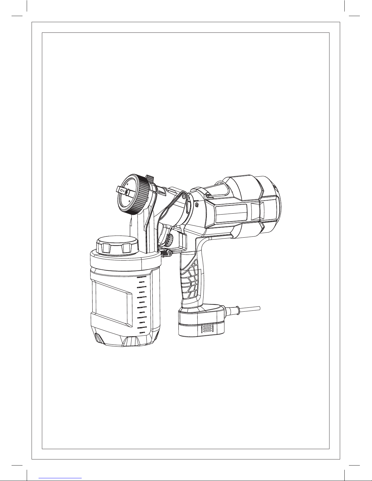
PLD3151S
Electric Spray Gun
English
Assembling & Use & Maintenance Manual
WARNING: READ INSTRUCTIONS MANUAL BEFORE USING PRODUCT.
Assembling & Use & Maintenance Manual
English
Electric Spray Gun
WARNING: READ INSTRUCTIONS MANUAL BEFORE USING PRODUCT.
Page 2
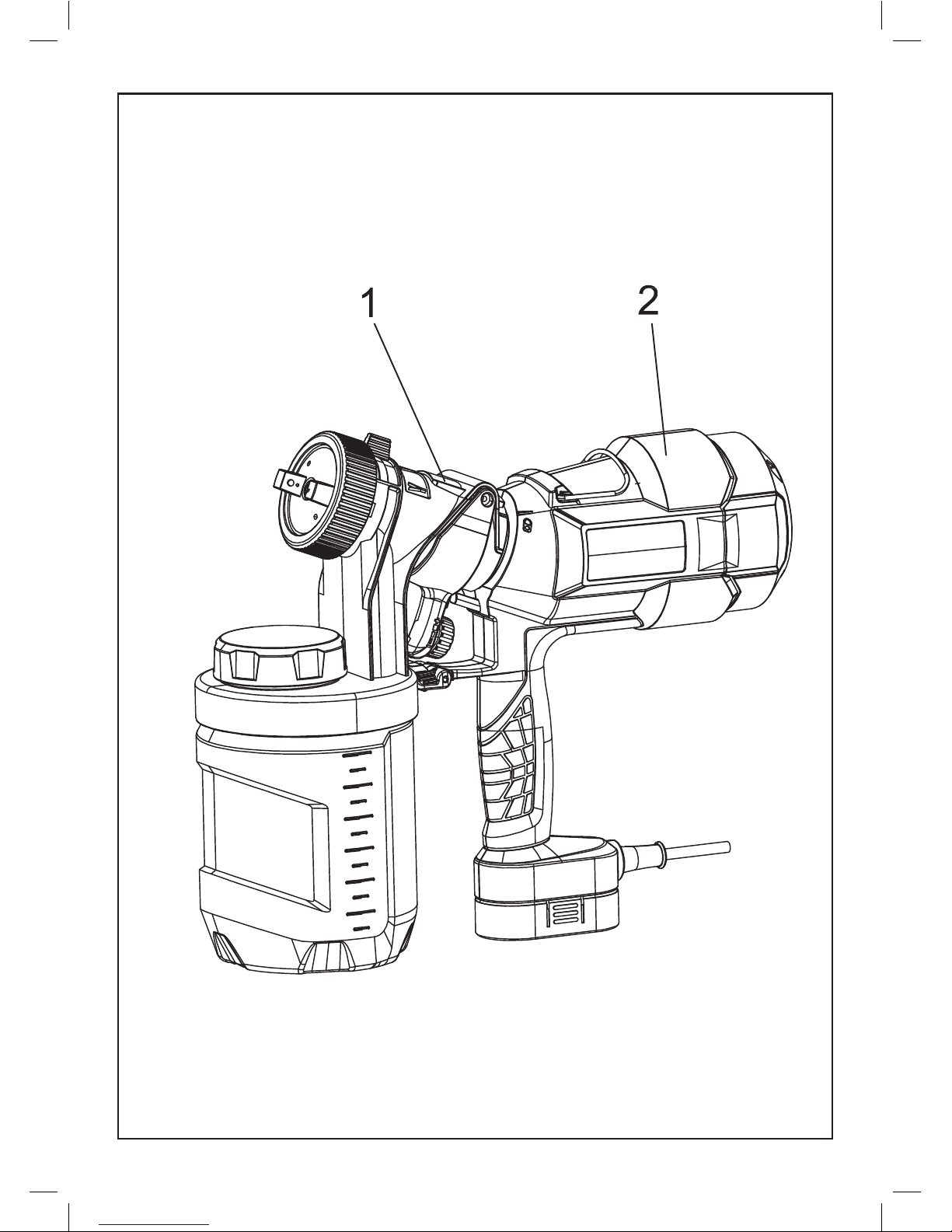
FIG. A
Spray gun unit Power unit
Spray gun unit Power unit
FIG. A
Page 3
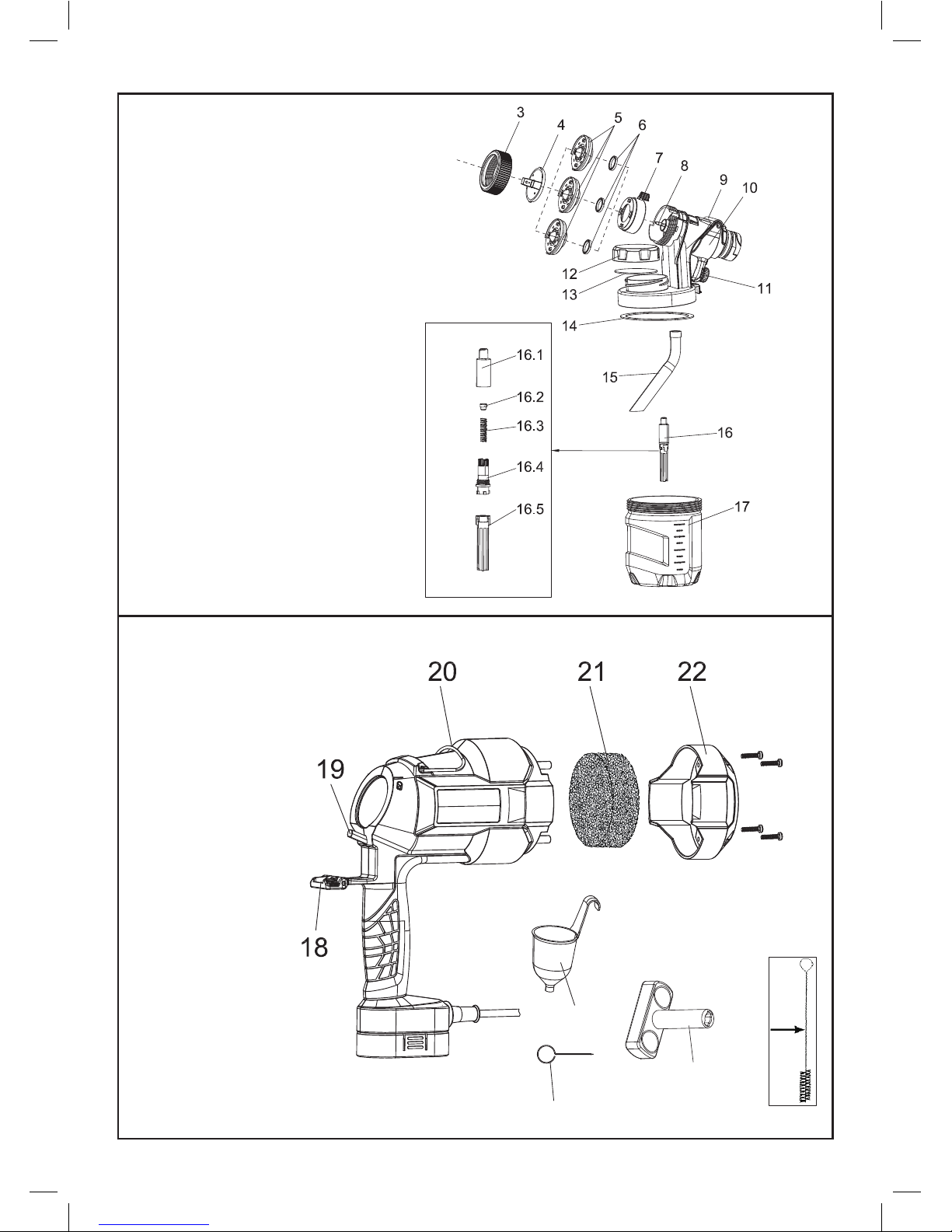
FIG. A1
FIG. A2
23
24
26
25
3.
4.
5.
6.
7.
8.
9.
10.
Tip collar
Air cap
Nozzle (Φ1.5mm/Φ2.5mm/Φ3.5mm)
Y-type seal ring
Spray width lever
Spray tip
Spray unit housing
11.
Trigger
12.
13. Sealing liner
14. O-ring
15. Pickup tube
16. Check valve assembly
16.1 Check valve sleeve 1
16.2 Check valve
16.3 Spring
16.4 Check valve sleeve 2
16.5 Valve extension
17. Canister
Flow control knob
Cleaning brush
Hanging hook
Switch trigger lever
18.
19.
Quick release lock
20.
21.
22.
Filter
23.
Filter cover
24.
Viscosity cup
25.
Cleaning needle
26. Spray tip key
FIG. A1
3. Tip collar
4. Air cap
5. Nozzle (Φ1.5mm/Φ3.5mm)
6. Y-type seal ring
7. Spray width lever
8. Spray tip
9. Spray unit housing
10. Trigger
11. Flow control knob
12. Quick rell lid
13. Sealing liner
14. O-ring
15. Pickup tube
16. Check valve assembly
16.1 Check valve sleeve 1
16.2 Check valve
16.3 Spring
16.4 Check valve sleeve 2
16.5 Valve extension
17. Canister
FIG. A2
18. Quick release lock
19. Switch trigger lever
20. Hanging hook
21. Filter
22. Filter cover
23. Viscosity cup
24. Cleaning needle
25. Cleaning brush
26. Spray tip key
Page 4
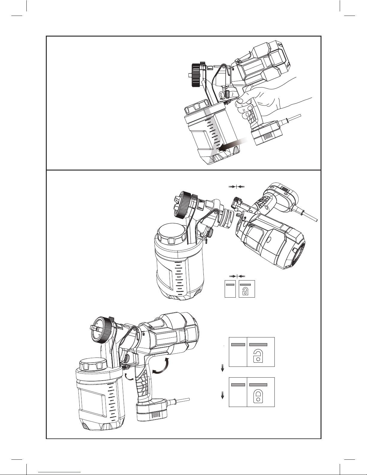
FIG. B
FIG. C
Attaching spray unit to spray gun handle
Aligning the pickup tube
The pickup tube (#15) needs to be aligned in the
direction toward the front of the canister .
This will ensure you spray as much material as
possible before you need to refill.
Make sure the pickup tube is assembled tight
in place.
Align the marking line on the spray
unit with the icon of unlock, then rotate
the spray gun handle clockwise until
stop. Rotate the quick release lock (#19)
and snap onto the hook on the edge
of canister lid.
FIG. B Aligning the pickup tube.
The pickup tube (#15) needs to be aligned in
the direction toward the front of the canister.
This will ensure you spray as much material as
possible before you need to rell. Make sure
the pickup tube is assembled tight in place.
FIG. C Attaching spray unit to spray gun handle.
Align the marking line on the spray unit with the
icon of unlock, then rotate the spray gun
handle clockwise until stop. Rotate the
quick release lock (#18) and snap onto
the hook on the edge of canister lid.
Page 5
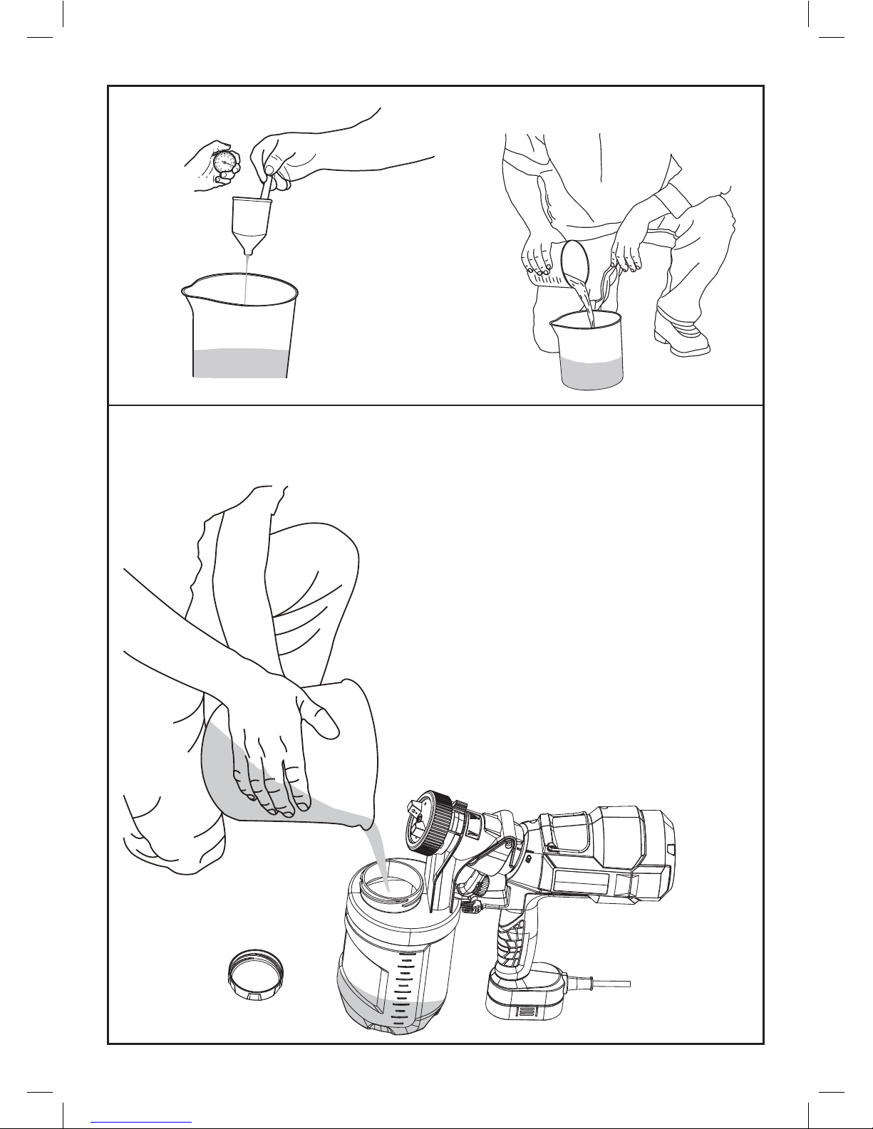
FIG. E
FIG. D
Filling the canister
1.Check to make sure that the canister is completely screwed
onto the sprayer.
2.Unscrew the quick refill lid ( #12 )
3.Stand the sprayer firmly on an smooth andhorizontal surface.
4.Pour the properly thinned and strained material to be sprayed
into the canister.
5.Clean any residual liquid from the threads or sides of the
the canister and sprayer.
6.Starting the threads evenly, screw the lid completely onto
the top fill canister. Check the lid to make sure it is threaded
on squarely and completely before picking up the sprayer.
FIG.D1
FIG. D FIG. D1
FIG. E Filling the canister.
1. Check to make sure that the canister is completely
screwed onto the sprayer.
2. Unscrew the quick rell lid (#12)
3. Stand the sprayer rmly on an smooth and horizontal surface.
4. Pour the properly thinned and strained material to be
sprayed into the canister.
5. Clean any residual liquid from the threads or sides of the
the canister and sprayer.
6. Starting the threads evenly, screw the lid completely onto the
top ll canister. Check the lid to make sure it is threaded on
squarely and completely before picking up the sprayer.
Page 6
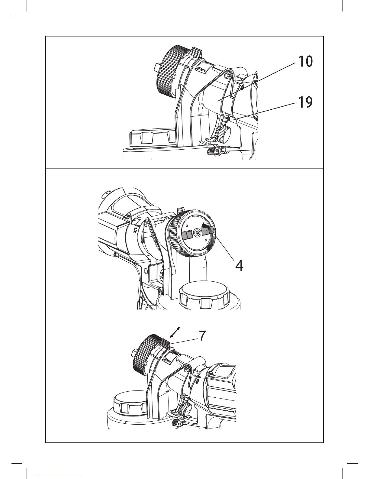
FIG. F
On / Off Switch
Squeeze to press the trigger (#10),
trigger will actuate the switch inside
the tool by the switch trigger lever
(#19) to turn on the tool. Release
the trigger to turn off the tool.
FIG.G Smart nozzle selection
Trigger
Switch trigger
lever
Air cap
Spray width lever
Page 7
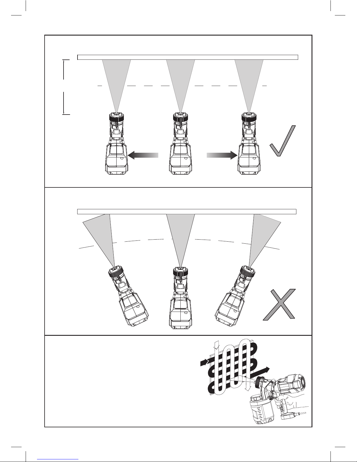
FIG. H
FIG. I
FIG. J
50 to 300mm
Always spray from a minimum of 50mm to a maximum of 300mm.
Avoid moving your wrist.
A commonly used method for spraying a large
surface is the “crisscross” pattern. This is done
by spraying in horizontal strips and then crossing
over these strips with vertical strips.
FIG. H
Always spray from a minimum of 2” to a maximum of 12”.
FIG. I
Avoid moving your wrist.
FIG. J
A commonly used method for spraying a large
surface is the “crisscross” pattern. This is done by
spraying in horizontal strips and then crossing over
these strips with vertical strips.
2’’ to 12’’
Page 8
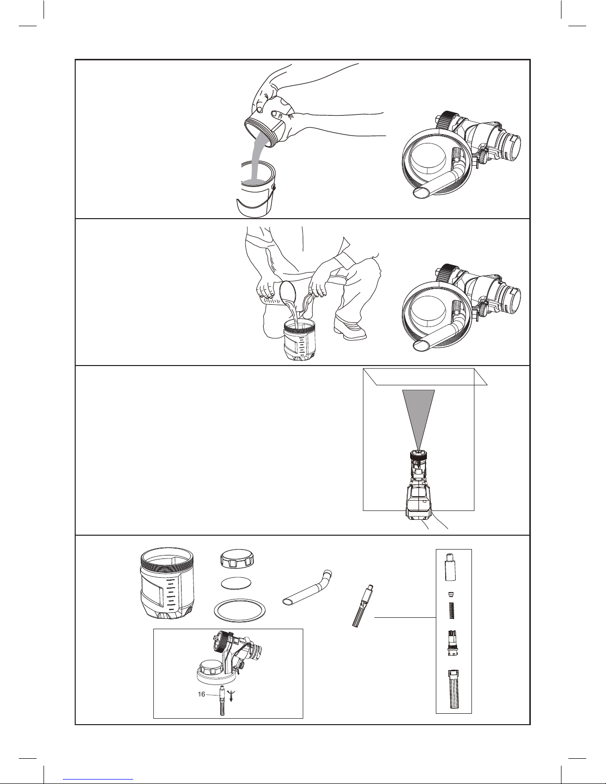
FIG. K
FIG. M
FIG. N
FIG. O
FIG. P1
Unscrew the canister from
the sprayer and pour any
remaining liquid back into
the original container
Pour a small amount of the
appropriate cleaning solution
into the canister
Spray the cleaning solution
through the sprayer onto scrap
material for 2 to 3 seconds
FIG. M
Pour a small amount of the appropriate
cleaning solution into the canister.
FIG. K
Unscrew the canister from the sprayer
and pour any remaining liquid back into
the original container.
FIG. N
Spray the cleaning solution through the sprayer onto
scrap material for 2 to 3 seconds.
FIG. O
FIG. O1
Page 9
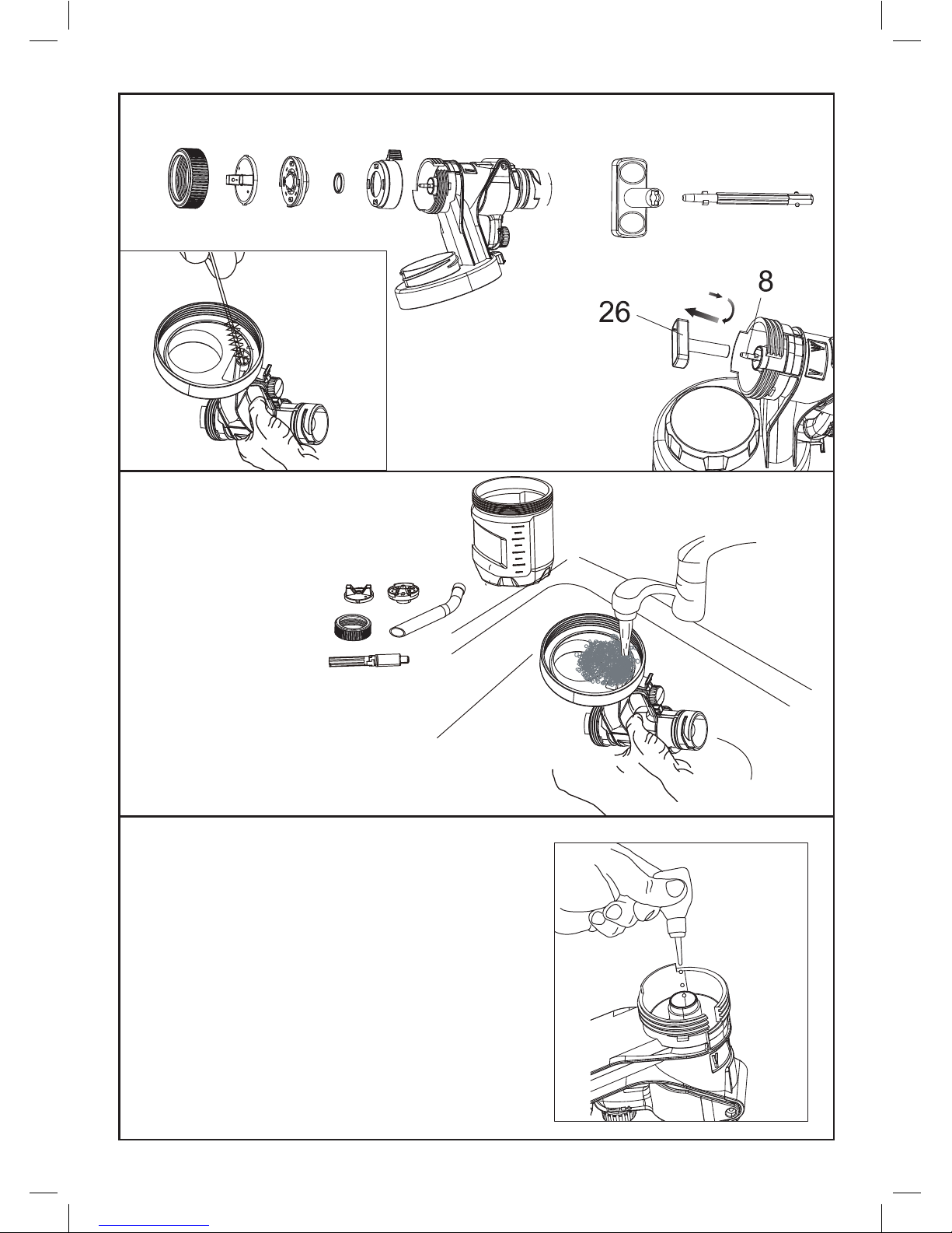
FIG. P
FIG.Q
FIG.R
90°
Spray tip key
Spray tip
Clean all parts with the
cleaning brush in the
appropriate cleaning
solution.
FIG.P1
1.If using water based material,
clean the sprayer by running
water through pickup tube
inlet.
2.If using oil based materials,
clean pickup tube inlet with
appropriate cleaning
solution.
Place a drop of household oil into the inside
of the sprayer from the hole for assembling the
spray tip
FIG. P FIG. P1
Spray tip key
Spray tip
Clean all parts with
the cleaning brush
in the appropriate
cleaning solution.
FIG. Q
1. If using water based material, clean the
sprayer by running water through pickup
tube inlet.
2. If using oil based materials,
clean pickup tube inlet
with appropriate cleaning
solution.
FIG. R
1. Place a drop of household oil into the
inside of the sprayer from the hole for
assembling the spray tip.
Page 10
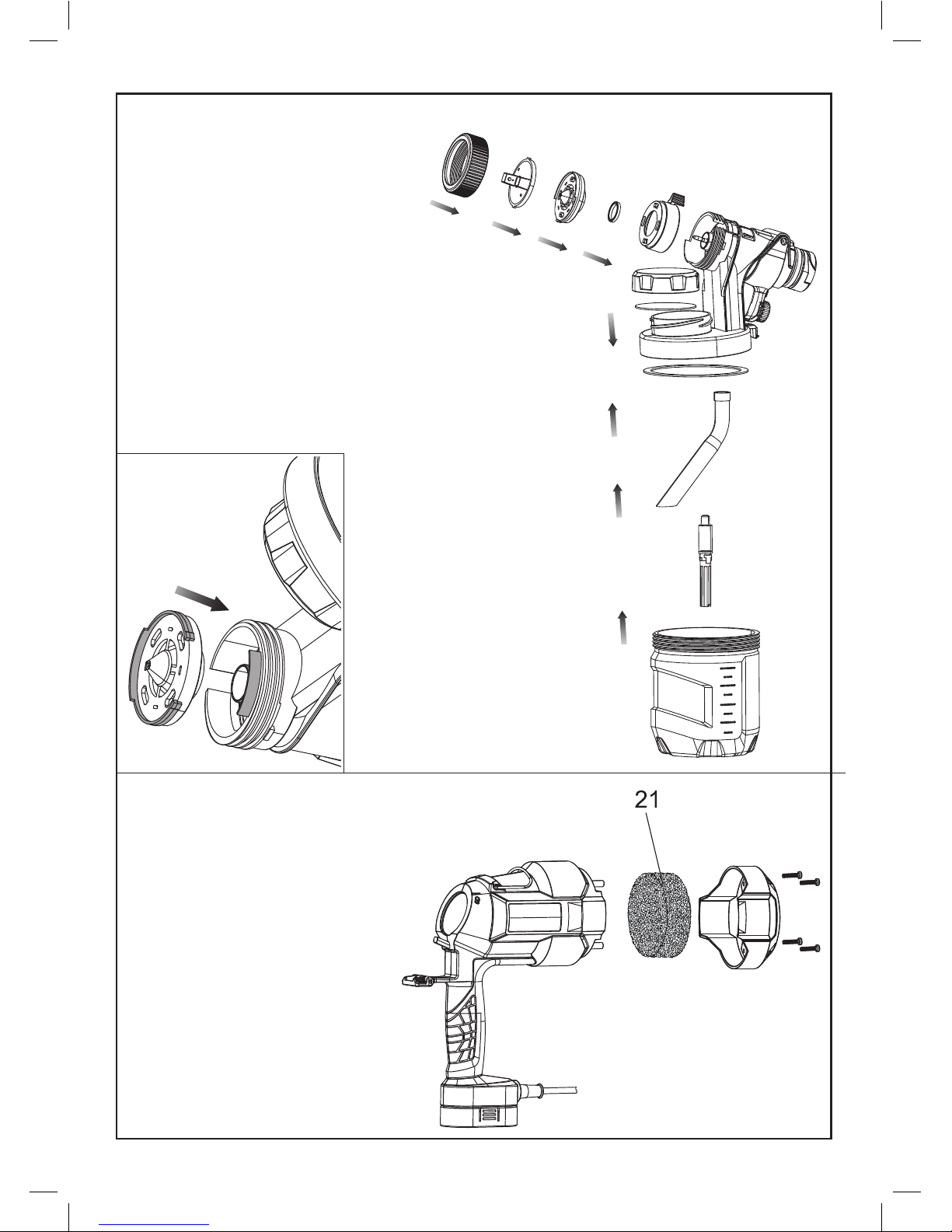
FIG. S
Filter
FIG.S1
Reassemble sprayer
Note: Spray nozzle can only be assembled in
one direction that the notch of the nozzle(#5)
must align with the skirt on spray unit
assembly.
Note: The spray tip must be assembled in
the sprayer with the bumps on the spray tip in
vertical direction
Note: Assemble the pickup tube(#15) and check
valve (#16) by firmly pushing them onto the inlet
on the sprayer.
Put all the accessories back into space.
FIG.T
The power unit contains A washable / reusable
flter (#21). Check the flter before and
after each use. If dirty, wash with warm water
and allow to air dry before re-installing or replace
if necessary
To check the filter,
Unscrew the screws on back
of the filter cover (#22)
and remove the filter cover(#22).
housing(#09). Refer to Fig. S1 for proper
FIG. S
Reassemble sprayer Note: Spray nozzle can
only be assembled in one direction that the
notch of the nozzle (#5) must align with the skirt
on spray unit housing (#9).
Refer to FIG. S1 for proper assembly.
Note: The spray tip must be assembled in the
sprayer with the bumps on the spray tip in ver
-
tical direction Note: Assemble the pickup tube
(#15) and check valve (#16) by rmly pushing
them onto the inlet on the sprayer.
Put all the accessories back into space.
FIG. T
The power unit contains A washable / reusable
ter (#21). Check the ter before and after
each use. If dirty, wash with warm water and
allow to air dry before re-installing or replace if
necessary.
To check the lter
Unscrew the screws on back of the lter cover
(#22) and remove the lter cover (#22).
FIG. S1
Filter
Page 11
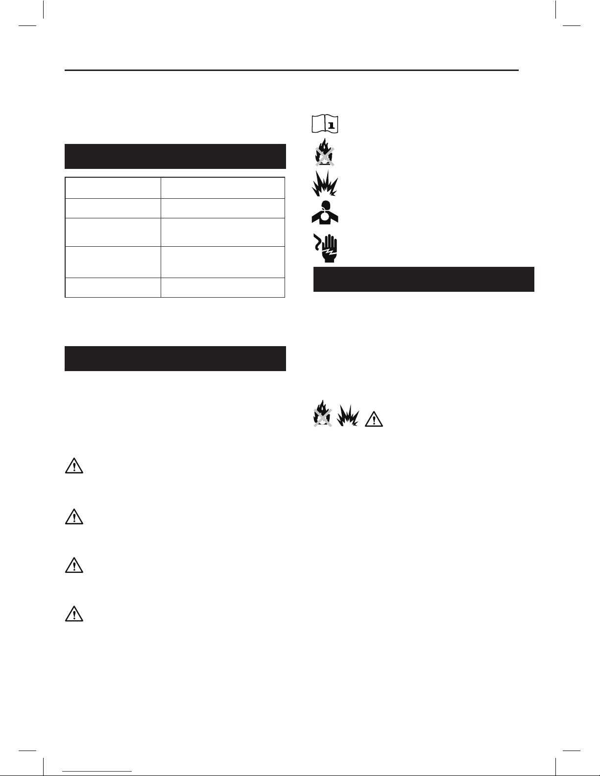
Read and understand the instruction manual.
Fire hazard.
Explosion hazard.
Respiratory hazard.
Electric shock hazard.
IMPORTANT SAFETY INSTRUCTIONS
TECHNICAL DATA
SAFETY GUIDELINES / DEFINITIONS
Current: 3.0A
Flow Rate: 900ml/min
Max. Viscosity:
100DIN-s
(runout time: 100 seconds)
Nozzle Size:
Φ1.5mm
Φ3.5mm
Container Capacity 1200ml
It is important for you to read and understand
this manual. The information it contains relates
to protecting YOUR SAFETY and PREVENTING
PROBLEMS. The symbols below are used to help
you recognize this information.
DANGER! Indicates an imminently hazardous
situation which, if not avoided, will result in
death or serious injury.
WARNING! Indicates a potentially hazardous
situation which, if not avoided, could result in
death or serious injury.
CAUTION! Indicates a potentially hazardous
situation which, if not avoided, may result in
minor or moderate injury.
NOTICE! Used without the safety alert sym-
bol indicates a potentially hazardous situation
which, if not avoided, may result in property
damage.
ENGLISH
The following are explanations of important
safety hazard pictorials in this manual.
SAVE THESE INSTRUCTIONS:
To reduce the risks of re or explosion, electrical
shock and the injury to persons, read and understand
all instructions included in this manual. Be familiar
with the controls and the proper usage of the
equipment.
THIS PRODUCT IS INTENDED FOR HOUSEHOLD
USE ONLY.
WARNING! FIRE OR EXPLOSION
HAZARD. Solvent and spray material fumes can
explode or ignite. Severe injury or property damage
can occur. To avoid these risks, take the following
preventions:
> Exhaust and fresh air introduction must be provided
to keep the air within the spray area.
>
Avoid all ignition sources such as static electricity
sparks, open ames, pilot lights, hot objects, lit tobacco
products, and sparks from connecting and disconnecting
power cords or working light switches.
> Fire extinguisher equipment shall be present and
working.
> Keep area clean and free of paint or solvent
> Follow the material and solvent manufacturer’s
safety precautions and warnings.
> Do not spray ammable or combustible materials
near an open ame or sources of ignition such as lit
tobacco products, motors, and electrical equipment.
Page 12
ENGLISH
> Know the contents of the spray materials and
their cleaning solvents. Read all Material Safety
Data Sheets (MSDS) and container labels
provided with the spray materials and solvents.
> Follow the spray material and solvent
manufacturer’s safety instructions. than 60ºC
(140ºF). Flashpoint is the temperature (see
coating supplies).
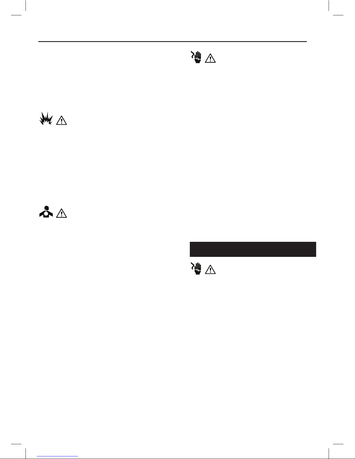
WARNING! EXPLOSION HAZARD
DUE TO INCOMPATIBLE MATERIALS. Severe
injury or property damage can occur. To avoid
these risks, take the following preventions:
> Do not use bleach.
> Do not use halogenated hydrocarbon solvents
such as methylene chloride and 1,1,1 trichloroethane. They are not compatible with
aluminum and may cause an explosion. If you
are unsure of a material’s compatibility with
aluminum, contact your coating supplier.
WARNING! HAZARDOUS VAPORS.
Spray materials, solvents, and other materials can
be harmful if inhaled or come in contact with the
body. Vapors can cause severe nausea, fainting,
or poisoning. To avoid these risks, take the
following preventions:
> Use a respirator or mask if vapors can be inhaled.
Read all instructions supplied with the mask to be
sure it will provide the necessary protection.
> Wear protective eyewear.
> Wear protective clothing as required by coating
manufacturer.
WARNING! ELECTRIC SHOCK
HAZARD. MAY CAUSE SEVERE INJURY.
To avoid these risks, take the following
preventions:
> Keep electrical cord plug and sprayer trigger free
from spray material and other liquids. Never hold
cord at plug connections to support cord. Failure
to observe may result in an electrical shock.
> Never immerse electrical parts in water or any
other liquid. Wipe the exterior of the sprayer with
a damp cloth for cleaning. Always make sure the
sprayer is unplugged before taking it apart for
cleaning.
> Do not expose unit to rain or wet conditions.
> Do not abuse the cord. Never use the cord to
carry the unit or pull the plug from an outlet. Keep
cord away from heat, oil, sharp edges or moving
parts. Replace damaged cords immediately.
GENERAL SAFETY WARNINGS
WARNING! GENERAL. To Reduce
the risk of severe injury or property damage. To
avoid these risks, take the following preventions:
> Do not aim the gun at, or spray any person,
including self, or animal.
> Do not spray outdoors on windy days.
> Wear protective clothing to keep spray material
off skin and hair.
>
Hose may become hot and cause skin burn.
> Follow all appropriate local, state, and national
operation.
> Always use appropriate gloves, eye protection
and a respirator or mask when spraying, thinning,
mixing, pouring, or cleaning.
> Do not operate or spray near children. Keep
children away from equipment at all times. Keep
sprayer out of the reach of children.
> Do not overreach or stand on an unstable support.
Keep effective footing and balance at all times.
Page 13
ENGLISH
> Stay alert and watch what you are doing.
> Do not operate the unit when fatigued or under
the inuence of drugs or alcohol.
> Read all instructions and safety precautions for
equipmen t and spray material before operating
any equipment.
>
Hearing protection is recommended for extended
use.
This tool is double insulated; therefore no
earth wire is required. Always check that the power
supply corresponds to the voltage on the rating plate.
> If the supply cord is damaged, it must be replaced
by the manufacturer or an authorised Service
Centre in order to avoid a hazard.
> When using the tool outdoors, only use extension
cables intended for outdoor use. A suitable rated
extension cable of up to 30 meters can be used
without loss of power.
> Electric safety can be further improved by using a
high sensitivity.
Use only a 3-blade grounding plug and a 3-slot
receptacle that will accept the plug on the product.
Make sure your extension cord is in good condition.
When using an extension cord, be sure to use one
heavy enough to carry the current your product will
draw. An undersized cord will cause a drop in line
voltage resulting in loss of power and overheating.
If an extension cord is to be used after the cord type
designation. For example, a designation of SJTW-A
would indicate that the cord would be appropriate
for outdoor use. For proper size cords see chart.
GUIDE FOR EXTENSION CORD USAGE:
Type of cable Up to 5 metres
From
5 to metres
10 metres
Parallel 2x 1.0mm
2
2x 1.5mm
2
WARNING! Some spray materials contain
chemicals known to cause cancer, birth defects or
other reproductive harm. To reduce your exposure
wear appropriate safety equipment such as face
masks, gloves, and other appropriate protective
equipment. Please review and follow the safety
precautions on the paint container.
FEATURES (FIG. A, FIG. A1, FIG. A2)
1. Spray gun unit
2. Power unit
3. Tip collar
4. Air cap
5. Nozzle (Φ1.5mm/Φ3.5mm)
6. Y-type seal ring
7. Spray width lever
8. Spray tip
9. Spray unit housing
10. Trigger
11. Flow control knob
12. Quick rell lid
13. Sealing liner
14. O-ring
15. Pickup tube
16. Check valve assembly
16.1 Check valve sleeve 1
16.2 Check valve
16.3 Spring
16.4 Check valve sleeve 2
16.5 Valve extension
17. Canister
18. Quick release lock
19. Switch trigger lever
20. Hanging hook
21. Filter
22. Filter cover
23. Viscosity cup
24. Cleaning needle
25. Cleaning brush
26. Spray tip key
ELECTRICAL SAFETY
EXTENSION CORD
Page 14

ENGLISH
WARNING! Be sure to use appropriate
protective gear and unplug unit.
WARNING! Make sure area is well ventilated.
Aligning the pickup tube (FIG. B) The pickup tube
(#15) needs to be aligned in the direction toward
the front of the canister ( FIG. B). This will ensure
you spray as much material as Make sure the
pickup tube is assembled tight in place.
Attaching spray unit to spray gun handle (FIG. C)
Align the marking line on the spray unit with the
icon of unlock, then rotate the spray gun handle
clockwise until stop. Rotate the quick release
lock (#18) and snap onto the hook on the edge of
canister lid.
Liquid material preparation (FIG. D AND D1) Tip:
Make sure the type of material you use can be
cleaned with either mineral spirits or paint thinner
(for oil-based paints) or a warm water and soap
solution (for water soluble paints like latex).
Use drop cloths during pouring, mixing, and
viscosity testing of materials to be sprayed to
protect your oors and anything else in the
spraying area that you wish to remain untouched.
The liquid being sprayed may need to be
thinned (diluted) before starting. When
thinning, use the proper liquid thinner
recommended on the container by the
material manufacturer.
WARNING!: Do not use materials with a
ashpoint higher than 60ºC (140ºF).
A viscosity test cup is provided to determine
the“runout time” of the material being used.
> Before measuring for the proper viscosity, stir the
material thoroughly.
> Dip the viscosity cup into the material being.
> With the cup held over the material container,
measure the amount of time it takes for the being
a constant stream out of the bottom of the cup (70
seconds or less) (FIG. D). This is the “runout time”.
Refer to the thinning table for information on the
thinning required for different materials.
> If material needs thinning, add the appropriate
liquid, thinning material recommended by the
manufacturer (FIG. D1).
> It is possible to spray latex paint with this unit,
however, the required thinning may exceed
material manufacturer’s recommendation. Thin
latex paint so that it runs through viscosity cup
within 70 seconds. The operator should consider
the type of application and nal location of the
project when spraying a material that requires
more than 70 seconds to run through the
viscosity cup. Unscrew the quick rell lid (#12)
SET / UP
Page 15
ENGLISH
OPERATION
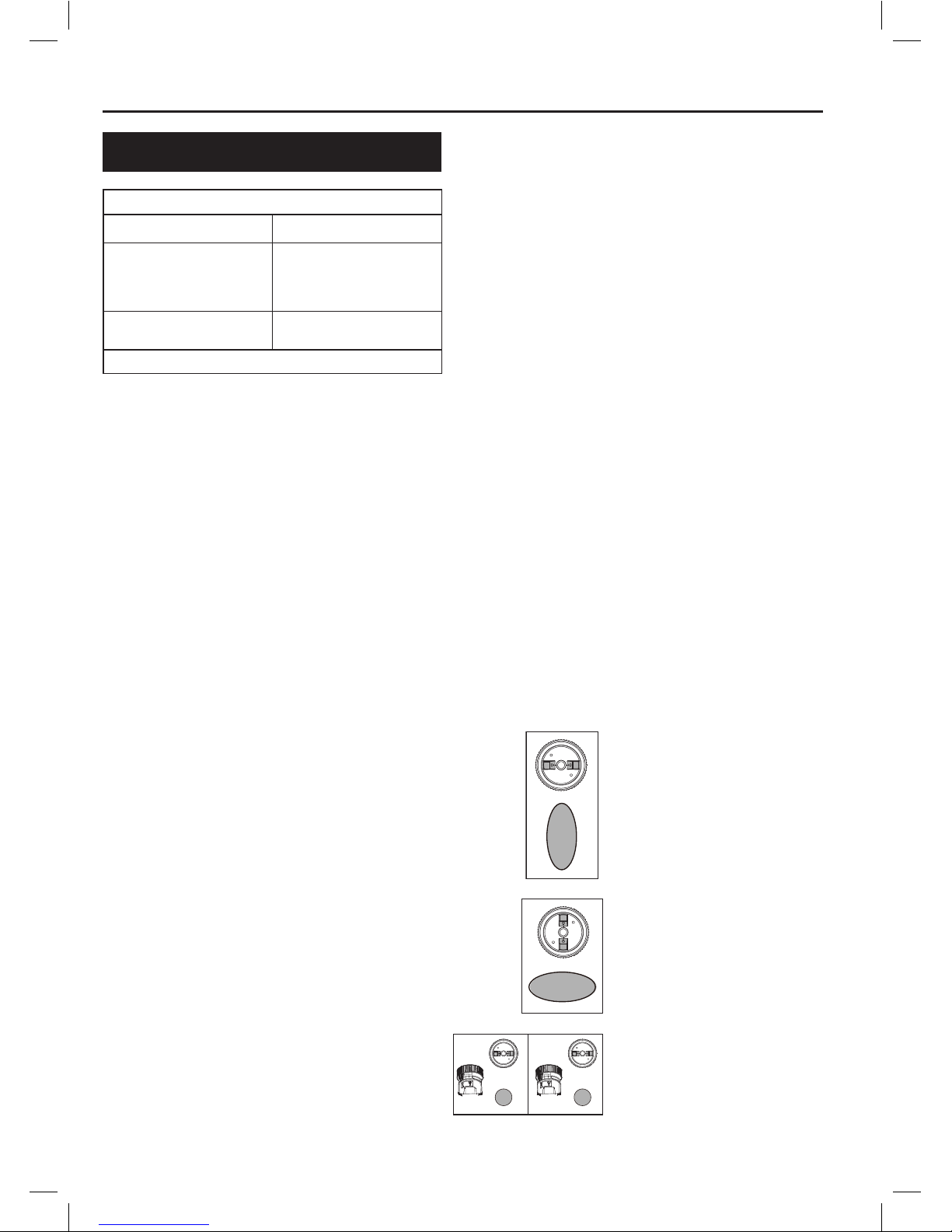
THINNING TABLE
SPRAY MATERIAL RUNOUT TIME
Clear and semi- transparent
stains and sealers
Oil based primers, varnishes
and polyurethane.
No thinning required (Less
than 70 seconds runout)
Solid color water based stains
Water based or latex paints.
May require thinning (More
than 70 seconds runout)
Note: Not recommended for textured paint.
PREPARATION TIPS
> Always stir and strain the material thoroughly
before use.
> With any spraying job you should always ensure
that you have properly prepared the are free from
dust, dirt, rust and grease. Lightly pressure wash
decks or exterior surfaces and ensure that they
are dry before spraying.
> Even though HVLP sprayers have very little
overspray, it is recommended that you mask all
edges and other areas and use drop cloths to
protect your oors and anything else in the spraying
area that you wish to remain untouched.
> Skin that forms on the top of paint can clog the
sprayer. Remove skin before mixing. Strain with
to remove any impurities that could clog system.
> Before starting have gloves, paper towels, rags
etc. available for unexpected spills.
FILLING THE CANISTER (FIG. E)
> Check to make sure that the canister is
completely screwed onto the sprayer.
> Unscrew the quick rell lid (#12)
> Stand the sprayer rmly on an smooth and
horizontal surface.
> Pour the properly thinned and strained material to
be sprayed into the canister (FIG. E).
> Clean any residual liquid from the threads or
sides of the canister and sprayer.
> Starting the threads evenly, screw the lid
completely onto the top ll canister. Check the
lid to make sure it is threaded on squarely and
completely before picking up the sprayer.
ON / OFF SWITCH (FIG. F),
Squeeze to press the trigger (#10), trigger will
actuate the switch inside the tool by the switch
trigger lever (#19) to turn on the tool. Release the
trigger to turn off the tool.
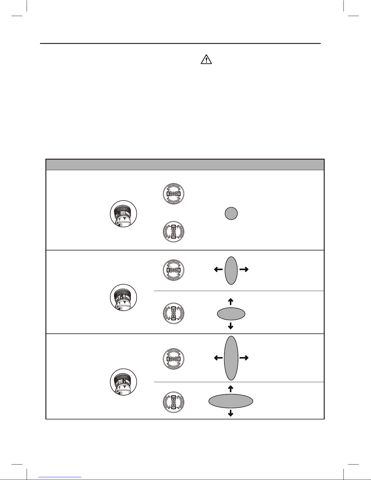
NOZZLE SELECTION (FIG. G)
There are three spray patterns to choose from:
- Vertical Flat Jet
- Horizontal Flat Jet
- Circular Jet
To select Vertical Flat Jet,
turn the air cap (#4) to
horizontal direction by turning
tip collar (#3) clockwise until
stop.
To select Horizontal Flat Jet,
turn the air cap (#4) to vertical
direction by turning tip collar
(#3) anti- clockwise until stop.
To select Circular Jet, turn he
Width Lever (#7) to the icon of
Minimum.
Page 16
ENGLISH
Vertical narrow jet for
horizontal coating
direction
Horizontal narrow jet
for vertical coatiang
direction
Vertical wide jet for
horizontal coating
direction
Horizontal wide jet
for vertical coating
direction
Small-medium
size surface
Large size
surface top
coating
Initial coatings,
corners, edges,
and hard to reach
locations
Small circular jet
Application Spray Width Lever #8 Air Cap #5 Spray Jet Pattern
There are three spray patterns to choose from:
- Vertical Flat Jet - Horizontal Flat Jet
- Circular Jet
Turning the smart
nozzle selector
(#3) clockwise
until stop.
Turning the smart
nozzle selector
(#3) clockwise
until stop.
Turn the Spray
Width Lever (#8)
Minimum.
to the icon of
Application
Air cap (#4) Spray Jet pattern
Spray with (#7) lever
Initial coatings,
corners, edges,
and hard to reach
locations
Small circular jet
Vertical narrow jet for
horizontal coating
direction
Vertical wide jet for
horizontal coating
direction
Horizontal narrow jet
for vertical coatiang
direction
Horizontal wide jet
for vertical coating
direction
Small-medium
size surface
Large size
surface top
coating
Note: Spray nozzle can only be assembled in one
direction that the notch of the nozzle (#5) must
align with the skirt on spray unit the housing (#9).
Refer to FIG. S1 for proper assembly.
WARNING! RISK OF INJURY. Never point
the Spray sprayer at any part of the body. Never pull
trigger while adjusting the spray setting.
ADJUSTING WIDTH OF SPRAY PATTERN
By turning the Spray Width Lever (#7) between
the Minimum marking and Maximum marking
the width of the spray patterns can be adjusted
accordingly.
Page 17

ENGLISH
FLOW CONTROL KNOB (FIG. A1)
The ow control knob (#11) regulates the amount
of liquid that can be sprayed. Turning the ow knob
clockwise increases the ow of liquid. Turning the
knob counter anti-clockwise decreases the ow of
liquid.
Tip: Always test the spray pattern on scrap
cardboard or similar material rst. Begin with ow
control knob on the highest ow setting. If less ow is
desired, dial the ow control knob anti- clockwise to
decrease the ow of liquid. Heavier, thicker materials
should be sprayed with the ow control knob on high
ow setting. Thinner materials should be sprayed
with the ow control knob on low ow setting.
> Practice spraying on a piece of scrap material
such as cardboard to test your spray pattern and
become familiar with the ow control feature of the
sprayer.
> Ensure surface to be sprayed is free of dust, dirt,
and grease.
> Ensure spray area is clean and free of dust that
could be blown onto newly sprayed surfaces.
> Cover any areas not intended to be sprayed.
>
Always spray from a minimum of 2 in to a maximum
of 12 in (FIG. H).
> A commonly used method for spraying a large
surface is the “crisscross” pattern. This is done by
spraying in horizontal strips and then crossing over
these strips with vertical strips (FIG. J).
> To get an even spray distribution, always keep your
arm at the same distance (FIG. H) from the surface
you are spraying and avoid moving your wrist
(FIG. I).
> Maintain smooth and consistent speed which will
help avoid inconsistencies. Begin spraying after
the pass has begun and release trigger before
stopping the pass.
> Avoid spraying too heavily in any one area. Several
lighter coats are better than one heavy coat which
can lead to running and dripping. Remember that
the ow control knob regulates the amount of
liquid that can be sprayed. Turning the ow knob
clockwise increases the ow of liquid. Turning the
knob counterclockwise decreases the ow of liquid.
If runs or drips do occur, have a dry paint brush on
hand to smooth them out.
> Turn the power unit off and unlpug the cord when
not spraying for any length of time.
WARNING! Be sure to use appropriate
protective gear.
> Do not use materials with a ashpoint higher than
60°C (140°F) . Flashpoint is the temperature that
a uid can produce enough vapors to ignite (see
coating supplier).
> Make sure clean up area is well ventilated and free
of ammable vapors.
> Always spray outdoors when spraying cleaning
solution through sprayer.
> Do not submerse power unit.
> Use drop cloths during pouring, mixing, and
viscosity testing of materials to be sprayed to
protect your oors and anything else in the
spraying area that you wish to remain untouched.
TO BEGIN CLEANING:
> Turn the power unit off, unplug the cord and
disconnect air hose from sprayer.
> Unscrew the canister from the sprayer and
pour any remaining liquid back into the original
container (FIG. K).
> Pour a small amount of the appropriate cleaning
solution into the canister (FIG. M). - Warm soapy
water for water based materials - Manufacturers
recommended cleaning solution for oil based
materials.
> Screw on the canister back to the sprayer securely
and vigorously shake the sprayer.
> Unscrew the canister and properly dispose of
cleaning solution.
> Rell the canister with a small amount of new
cleaning solution. Screw on the canister back the
sprayer. Reattach the spray gun unit to the power
unit, plug in the cord and turn on the power unit.
> Spray the cleaning solution through the sprayer
onto scrap material for 2 to 3 seconds (FIG. N).
> Turn the power unit off, and unplug the cord.
> Unscrew the canister from the sprayer.
DEVELOPING THE PROPER
SPRAYING TECHNIQUE
CLEANING
Page 18

ENGLISH
> Remove the o-ring (#14), pickup tube (#15), check
valve (#16), and quick rell lid (#12) from the
sprayer. Clean the parts with the cleaning brush in
the appropriate cleaning solution (FIG. O). Note:
When removing the check valve, twist the check
valve clockwise and then pull it out. (FIG O1).
> Unscrew the tip collar (#3) and remove all the
parts of the spray nozzle (#3,#4,#5,#6,#7.#8) from
the sprayer. Remove the spray tip (#8) from the
sprayer (FIG. P1). Clean all parts with the cleaning
brush in the appropriate cleaning solution (FIG. P,
FIG.P1). Be sure to clean around check valve with
brush (FIG. P INSERT).
> If using water based material, clean the sprayer by
running water through pickup tube inlet as shown
in FIG. Q. If using oil based materials, clean pickup
tube inlet with the appropriate cleaning solution.
Repeat until sprayer is completely clean.
> Dry all parts thoroughly.
> Place a drop of household oil into the inside of the
sprayer from the hole for assembling the spray tip
(FIG. R).
> Reassemble sprayer (FIG. S).
Note: Spray nozzle can only be assembled in one
direction that the notch of the nozzle (#5) must align
with the skirt on spray unit housing (#9). Refer to
FIG. S for proper assembly.
Note: The spray tip must be assembled in the
sprayer with the bumps on the spray tip in vertical
direction Note: Assemble the pickup tube (#15) and
check valve (#16) by rmly pushing them onto the
inlet on the sprayer.
> Put all the accessories back into space.
Use only mild soap and damp cloth to clean the
power unit. Never let any liquid get inside the power
unit; never immerse any part of the power unit into
a liquid.
IMPORTANT! To assure product SAFETY
and RELIABILITY, repairs, maintenance and
adjustment (other than those listed in this manual)
should be performed by authorized service centers
or other qualied service personnel, always using
identical replacement parts. The power unit contains
A washable / reusable ter (#21). Check the ter
before and after each use. If dirty, wash with warm
water and allow to air dry before re-installing or
replace if necessary (FIG. T).
> To check the lter, Unscrew the screws on back
of the lter cover (#22) and remove the lter
cover (#22).
Remove the lter as shown in FIG. T and inspect.
Reassemble the ter and ter cover.
IMPORTANT ! Never operate the power unit
without the lter in place. Debris could be sucked in
and interfere with the function of the power unit.être
MAINTENANCE
Page 19

ENGLISH
Make sure unit is clean and dry before storing. Store
unit indoors in a dry location. To prevent damage,
wrap the electrical cord so that it is not crimped during
storage.
Recommended accessories for use with your product
are available from your local dealer or authorized
service center.
WARNING! The use of any accessory not
recommended for use with this product could be
hazardous.
Separate collection. This product must not
be disposed of with normal day that your
product needs replacement, or if it is of no
further use to you, do not dispose of it with
household waste. Make this product
available for separate collection.
Separate collection of used products
and packaging allows materials to be
recycled and used again. Re-use of
recycled materials helps prevent
environmental pollution and reduces
the demand for raw materials. Local
regulations may provide for separate collection of
electrical products from the household, at
municipal waste sites or by the retailer when you
purchase a new product.
STORAGE
ACCESSORIES
PROTECTING THE ENVIRONMENT
Page 20
ENGLISH
TROUBLESHOOTING
TROUBLE ! MATERIAL RUNS OR DRIPS.
WHAT’S WRONG? WHAT TO DO…
Spraying too much material. Reduce paint ow by turning material adjustment knob.
Spraying too slowly. Increase speed of application.
Spraying too close. Increase distance from surface.
Viscosity too thin. Check dilution recommendation.
TROUBLE! MATERIAL DRIPS FROM NOZZLE
WHAT’S WRONG? WHAT TO DO…
Nozzle loose. Screw nozzle tight.
Nozzle breaks. Change
Y-type seal ring of nozzle breaks. Change
Material accumulated /clog inside nozzle. Clean
TROUBLE! TOO MUCH OVER SPRAY.
WHAT’S WRONG? WHAT TO DO…
Sprayer too far from surface. Reduce distance to surface.
Too much material being sprayed. Reduce paint ow by turning ow control knob.
TROUBLE! LITTLE OR NO MATERIAL BEING RELEASED.
WHAT’S WRONG? WHAT TO DO…
Spray nozzle/tip clogged. Clean nozzles.
Y-type seal ring of nozzle missing. Add seal ring to nozzle and assemble in place.
Pickup tube loose or clogged. Check tube.
Canister loose. Screw canister tightly in place.
Quick rell lid loose. Screw quick rell lid tight in place.
Spray gun unit not fully attached to the power unit. Check attachment of spray gun unit.
Flow control knob setting too low. Increase ow control setting.
Air inlet blocked. Clean or change air lter.
Material too thick. Thin material per manufacturer recommendation.
TROUBLE! MATERIAL BEING SPRAYED IS SPLATTERING
WHAT’S WRONG? WHAT TO DO…
Viscosity of material is too high. Thin material per manufacturer recommendation.
Page 21
ENGLISH
TROUBLESHOOTING
TROUBLE! ATOMIZATION IS TOO COARSE
WHAT’S WRONG? WHAT TO DO…
Viscosity of material too high. Thin material per manufacturer recommendation.
Flow control knob setting too high. Decrease ow control setting.
Material accumulated /clog inside nozzle. Clean
Air inlet blocked. Clean or change air lter.
Canister loose Screw canister tightly in place.
Quick rell lid loose Screw quick rell lid tight in place.
TROUBLE! SPRAYER PULSATES.
WHAT’S WRONG? WHAT TO DO…
Air lter clogged. Clean or change air lter.
Material in canister almost empty.. Rell canister.
Canister loose. Screw canister tightly in place.
Quick rell lid loose. Screw quick rell lid tight in place.
TROUBLE! SPRAY MATERIAL DOES NOT COVER PROPERLY
WHAT’S WRONG? WHAT TO DO…
Flow control knob setting too low. Increase ow control setting.
Clearance to target area too large. Reduce spray distance.
Too few spray paths sprayed over target area. Apply more spray paths sprayed over target area.
Viscosity of material too high. Thin material per manufacturer recommendation.
 Loading...