

Page 1

WinFast® 33DD S320 II
User’s Manual
Leadtek Research Inc.
Page 2

WinFast 3D S320 II User’s Manual
i
Table Of Contents
Getting Started.................................................................................................... I
Accessories.........................................................................................................................................I
System Requirements.......................................................................................................................I
Connection Guide............................................................................................................................II
Chapter 1 Welcome to WinFast 3D S320 II.................................................... 1
1.1 Introduction............................................................................................................... .................1
1.2 Features........................................................................................................................................2
Chapter 2 Hardware Installation..................................................................... 3
2.1 Card Layout.................................................................................................................................3
2.2 Jumper Settings...........................................................................................................................5
Chapter 3 Software Installation....................................................................... 7
3.1 Windows 95/98..........................................................................................................................7
Page 3

Leadtek Research Inc.
ii
3.1.1 Installing WinFast 3D S320 II Drivers and DirectX 6 for Windows 95/98 ....7
3.1.2 Explanations for the WinFast 3D S320 II Display Properties.............................9
3.2 Windows NT 4.0......................................................................................................................20
3.2.1 Installation of Windows NT 4.0 with WinFast 3D S320 II...............................20
3.2.2 Install WinFast 3D S320 II Drivers for Windows NT4.0...................................20
3.3 Updating existing WinFast 3D S320 II Drivers for Windows 95/98............................23
3.4 BIOS Flash Utility.....................................................................................................................24
Chapter 4 TV Output (Optional) ................................................................... 25
Chapter 5 Digital Flat Panel Output (Optional).......................................... 27
Chapter 6 Display Modes Table ...................................................................... 29
Limited Warranty............................................................................................................................31
Calling for Te chnical Support.......................................................................................................32
Copyright, Trademark, Disclaimer Notes..................................................................................33
FEDERAL COMMUNICATIONS COMMISSION REQUIREMENTS..............................34
Page 4
WinFast 3D S320 II User’s Manual
I
Getting Started
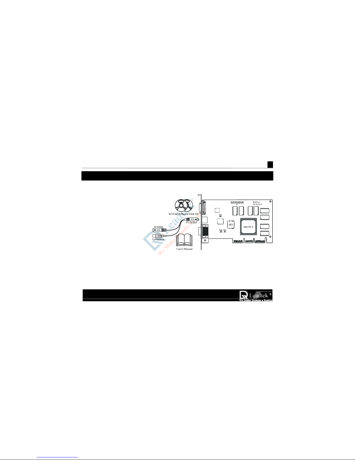
Accessories
• WinFast 3D S320 II
WinFast 3D S320 IIWinFast 3D S320 II
WinFast 3D S320 II card
• User‘s Manual
• WinFast software pack CD
( Including drivers for
Windows 95/98, Windows
NT 4.0, DirectX Runtime
Driver )
System Requirements
• Hardware : Pentium II or compatible system with AGP slot
• Operating system: Win 95/98 / Windows NT 4.0 with Service Pack 3 or later
Page 5
Leadtek Research Inc.
II
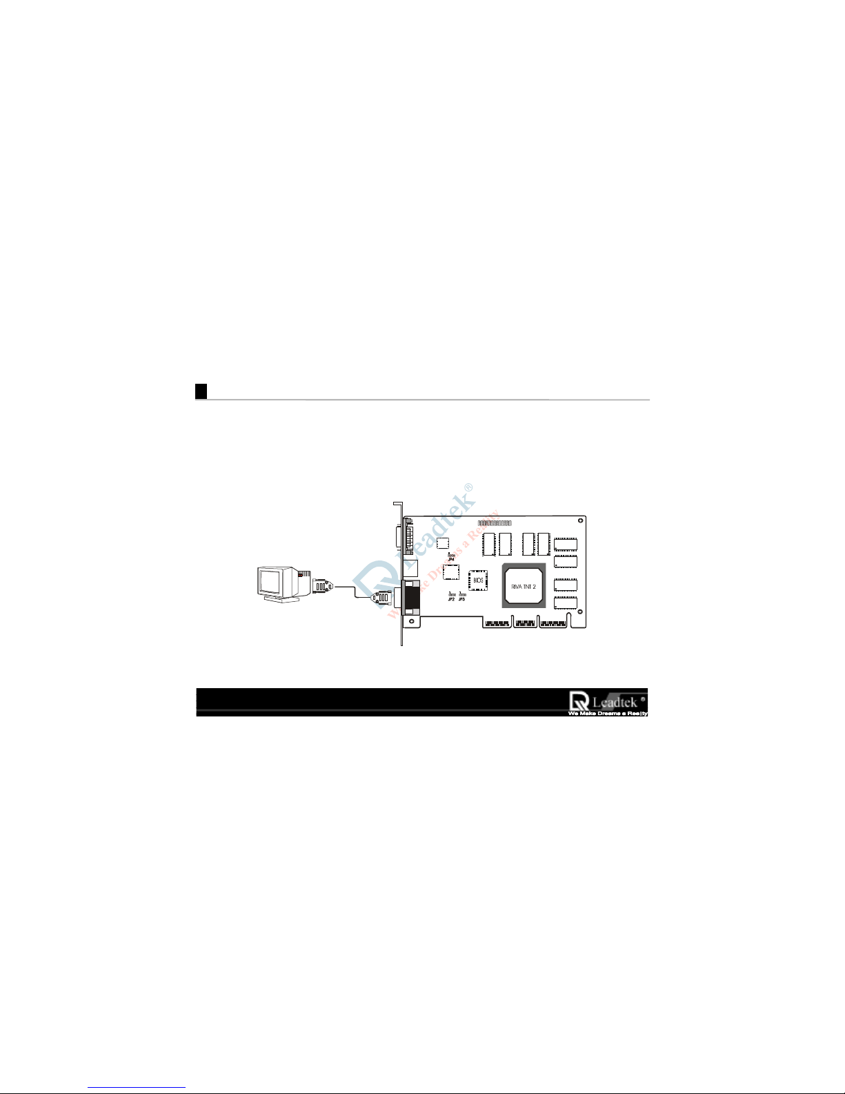
Connection Guide
Step 1 Insert the WinFast 3D S320 II
WinFast 3D S320 IIWinFast 3D S320 II
WinFast 3D S320 II card into an empt y AGP slot and fix it with screw on back panel.
JP1
WinFast
3D S320 II
V
GA Cable
Step 2 Plug the free end of the monitor cable into the video connector on the
WinFast 3D S320 II
WinFast 3D S320 IIWinFast 3D S320 II
WinFast 3D S320 II card.
Page 6

WinFast 3D S320 II User’s Manual
1
1
Welcome to WinFast 3D S320 II
1.1 Introduction
Congratulations! You have chosen one of the most powerful high
Congratulations! You have chosen one of the most powerful highCongratulations! You have chosen one of the most powerful high
Congratulations! You have chosen one of the most powerful high----end 3D accelerator cards. Leadtek’s
end 3D accelerator cards. Leadtek’s end 3D accelerator cards. Leadtek’s
end 3D accelerator cards. Leadtek’s
““““WinFast 3D S320 II
WinFast 3D S320 IIWinFast 3D S320 II
WinFast 3D S320 II” uses the
” uses the ” uses the
” uses the RIVA TNT II 3D processor c
3D processor c3D processor c
3D processor chip from
hip from hip from
hip from nVIDIA. The “
. Th e “. Th e “
. The “WinFast 3D S320 II
WinFast 3D S320 IIWinFast 3D S320 II
WinFast 3D S320 II”
” ”
”
introduces the most advanced Direct3D/OpenGL acceleration solution and also delivers leadership VGA,
introduces the most advanced Direct3D/OpenGL acceleration solution and also delivers leadership VGA, introduces the most advanced Direct3D/OpenGL acceleration solution and also delivers leadership VGA,
introduces the most advanced Direct3D/OpenGL acceleration solution and also delivers leadership VGA,
2D and Video performance, enabling a range of applications from 3D games through DVD and
2D and Video performance, enabling a range of applications from 3D games through DVD and 2D and Video performance, enabling a range of applications from 3D games through DVD and
2D and Video performance, enabling a range of applications from 3D games through DVD and
Multimedia applications
Multimedia applicationsMultimedia applications
Multimedia applications....
Page 7

Leadtek Research Inc . .
Leadtek Research Inc . .Leadtek Research Inc . .
Leadtek Research Inc . .
1.2 Features
• Fast 32-bit VGA / SVGA
• High performance 128-bit 2D / GUI / DirectDraw Acceleration
• 128-bit wide frame buffer interface supporting up to 32 Mbyte SDRAM/SGRAM
• Video Acceleration fo r D ir e ctShow, MPEG-1/2 and Indeo
.
• Optimized for Direct3D acceleration with complete support for DirectX 5.0 and 6.0
• Twin texel 32-bit graphics pipeline
• 32-bit RGB rendering with destination alpha
• 24-bit Z-buffer, 8-bit stencil buffer
• Anisotropic filtering (better than Tri-Linear MIP-mapping)
• 100% hardware triangle setup engine
• 300 MHz Palette-DAC supporting up to 2048 x 1536, Hi Color 60 Hz
• Video output for NTSC and PAL TV-output (Option)
• DDWG (Digital Display Wor king Group) compliant Digtal Flat Panel output up to 1280 x 1024
(Option)
• AGP 4x/2x with full sideband/Execute Mode support
Page 8
WinFast 3D S320 II User’s Manual
3
2
Hardware Installation
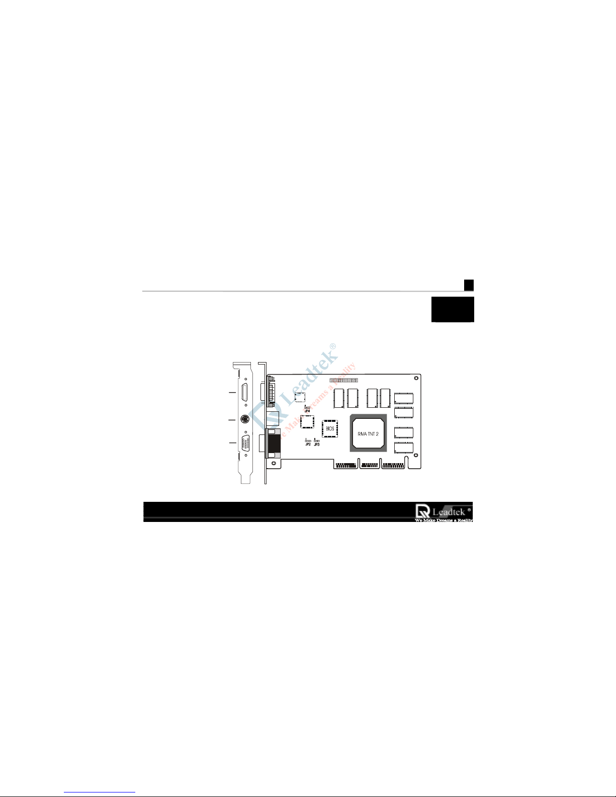
2.1 Card Layout
JP1
WinF ast
3D S320 II
VGA Connector
Digital Fl at Panel Output
(Option)
( SDRAM VERSION
)
TV Output
(Option)
Page 9
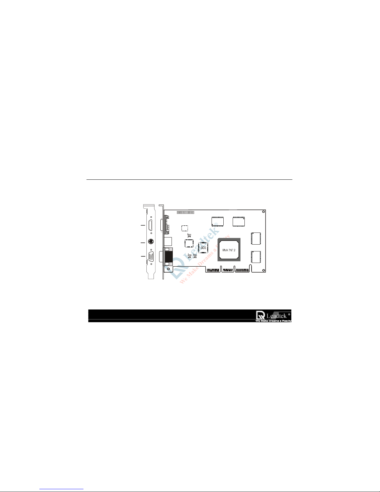
Leadtek Research Inc . .
Leadtek Research Inc . .Leadtek Research Inc . .
Leadtek Research Inc . .
JP1
WinFast
3D S320 II
VGA Connector
TV Output
(Option)
Digital Flat Panel Output
(Option)
( SGRAM VERSION )
Page 10
WinFast 3D S320 II User’s Manual
5
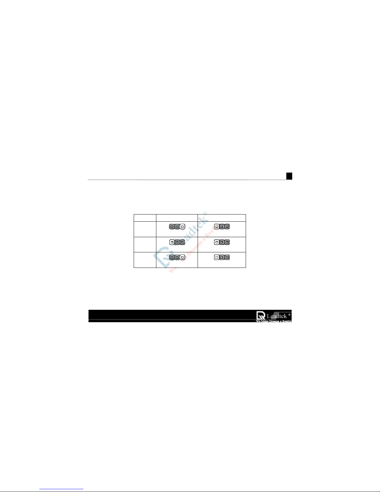
2.2 Jumper Settings
Please follows the jumper layout to set TV output format: for Version SDRAM and SGRAM:
Jumper
JumperJumper
Jumper
NTSC
NTSCNTSC
NTSC PAL
PALPAL
PAL
JP2
JP2JP2
JP2
123
123
JP3
JP3JP3
JP3
123 123
JP4
JP4JP4
JP4
123 123
Page 11

WinFast 3D S320 II User’s Manual
7
3
Software Installation
3.1 Windows 95/98
3.1.1Installing WinFast 3D S320 II Drivers and DirectX 6 for Windows 95/98
During the booting of Win95/98 after having inserted the WinFast 3D S320 II
WinFast 3D S320 IIWinFast 3D S320 II
WinFast 3D S320 II card into AGP slot, the new
installed hardware will be detected and the “Update Device Driver Wizard” window will appear on the
screen. At this point, if your machine has updated version of “VGA RTD” software installed then you can use
the “nv4agp.inf” file in the accompany CD to install the driver, otherwise lets Windows install the “Standard
PCI Graphics Adapter (VGA)” driver which Windows found.
When Standard VGA driver installation is complete, Windows will prompt you to restart your Windows.
Click “NO” to response the prompt and follows the steps described below for continuing installation:
Step 1 Insert the WinFast Software Pack CD into the CD-ROM drive.
Note: The WinFast 3D S320 II package contains the “WinFast Software Pack CD”
,
Please read the “Readme.txt
Readme.txtReadme.txt
Readme.txt” file in the “S320ii
S320iiS320ii
S320ii” sub-director
y
of the CD for the latest
information about the software before installation.
Page 12

Leadtek Research Inc..
Leadtek Research Inc..Leadtek Research Inc..
Leadtek Research Inc..
Step 2 The “Autorun” will be executed immediately and a “WinFast 3D S320/S320 II/S320 V
Installation Program” dialog with four selectable buttons will be shown on the screen. Click
the”Win9x” button to install the driver for Win95/98 automatically.
Step 3 When finishing the driver installation follow the screen direction “Restart” Windows 95/98.
Step 4 Eject the CD-ROM and load WinFast Software Pack CD again. Click the “DirectX 6” button
to install the DirectX 6 to your machine for better 3D performance.
Note:
Note:Note:
Note: If the autorun function is not enabled on your machine. Please find the “Install.exe” file in the root
directory of CD and double click it to install the software automatically.
Page 13

WinFast 3D S320 II User’s Manual
9
3.1.2 Explanations for the WinFast 3D
S320 II Display Properties
W
hen drivers were installed properly, r ight click on
Win95/98 desktop wallpaper area and select
“Properties
Propert i esPropert i es
Properties” item. A window with a title name
“Display Properties
Display PropertiesDisplay Properties
Display Proper ties” will appear on your screen as
shown on the right.
NOTE: Please enable the Monitor Protective
Setting by click the check box to protect
your monitor. This sets the ra nge of
display modes such as Refresh Rate,
Display Area you can select according to
your specific monitor manufacturer.
Click the “Advance…
Advance…Advance…
Advance…” button, another sheet of
“Additional Properties
Additional PropertiesAdditional Properties
Additional Properties” will be shown as on next
page.
Page 14

Leadtek Research Inc . .
Leadtek Research Inc . .Leadtek Research Inc . .
Leadtek Research Inc . .
“Direct3D” Tab
The RIVA TNT II can automatically generate
mipmaps to increase the efficiency of texture
t
ransfers across the bus and provide higher
application performance.
However, some applications may not display
correctly when auto-generated mipmaps are
enabled. To correct any problems, reduce the
number of automatically generated mipmap levels
until the images are properly displayed. Reducing
t
he number of mipmap levels can often eliminate
t
exture misalignment or "seaming" (at the expense
of some performance).
Properties
Page 15

WinFast 3D S320 II User’s Manual
11
All
ows you to select the auto-mipma
pping
method
used b
y
the RIVA TNT II.
You can select either the bilinear or trilinear
mipmapping method, whereby the bilinear method
generally provides better performance, while the
t
rilinear method generally produces a higher quali ty
ima
g
e.
This o
p
tion allows for dithering of trilinear mipmaps.
Allowin
g
mipmap dithering will provide increased
a
pp
lication performance at the expense of some
ima
ge q
uality. In some cases, a loss of image qualit
y
may not be noticeable, so you may wish to take
advanta
g
e of the extra performance gained b
y
enabling this feature.
Th
ese options allow you to control the anti-aliasing
features of the drivers
Anti-aliasing i
s a method used to smooth edges of
3D objects to eliminate a jagged appearance. Note
t
hat enabling anti-aliasing will not automatically
cause all Direct3D programs to render anti-aliased
images. Anti-aliasing must be supported by the
a
pp
lication in order for it to work properly.
Properties
Page 16

Leadtek Research Inc . .
Leadtek Research Inc . .Leadtek Research Inc . .
Leadtek Research Inc . .
Allows you to adjust the LOD (Level of Detail) bias
for mi
pmap
s.
A lower bias will
p
rovide better image quality, while
a higher bias will increase application performance.
You can choose from five preset bias values, va rying
from "Best Ima
g
e Quality" to "Best Performance"
Allows you to select the anti-aliasing sampling
method.
You can ad
j
ust the settings to values which range
from providing the fastest applic ation performance
t
o rendering the highest quality image.
Lets
y
ou save the current settings as a custom
"tweak". Saved settings will then be added to the
ad
j
acent list.
Once
y
ou have found the optimal settings for a
particular Direct3D application, saving the settings
as a custom tweak allows you to quickly configure
Direct3D before starting the program and
eliminates the need to set each of the options
individuall
y
.
Displays a dialog which allows you to customize
additional Direct3D settings for the RIVA TNT II as
shown on next
pag
e.
Properties
Page 17

WinFast 3D S320 II User’s Manual
13
This option is used to turn fog table emulation on
or off.
Direct3D s
p
ecifies that a display adapter capable of
D3D hardware acceleration should be able to
implement either vertex fog or table fog. Some
games do not correctly query the D3D hardware
capabilities and expect table fog support. Choosing
t
his option will ensure that such games will run
prop
erly on the RIVA TNT II.
This o
p
tion allows you to disable the DirectX 6
features of the drivers.
Some
g
ames written for earlier versions o f DirectX
may not run properly with DirectX 6 installed and
t
he DirectX 6 support enabled in the drivers.
Selecting this option forces the drivers to run in
DirectX 5 compatibility mode so that older games
will run correctl
y
.
Use this o
p
tion if you wish to run certain older
games that do not start or do not run as they
should.
Continued on next
pag
e…..
Page 18

Leadtek Research Inc . .
Leadtek Research Inc . .Leadtek Research Inc . .
Leadtek Research Inc . .
This option changes the hardware texture addressing scheme for
t
exels (texture elements).
Changing these values will change where texel origin is defined. The
default values conform to the Direct3D specifications. Some
software may expect the texel origin to be defined elsewhere. The
image quality of such applications will improve if the texel origin is
redefined. Use the slider control to adjust the texel origin anywhere
between the upper left corner and the center of the texel.
Allows you to specify the maximum size of the PCI texture heap.
Increasing this value on PCI systems with sufficient memory may
significantly improve the performance of some Direct3D
applications.
For performance reasons, this utility will not allow you to set the
value to more than one half of the available system memory as
reported by Windows.
This o
p
tion is not available on display adapters which use the AGP
bus.
This option allows you to limit the number of frames the CPU can prepare before they are processed by the
RIVA TNT II (when VSYNC is disabled).
In some cases, the higher the number of pre-rendered frames allowed, the greater the "input lag" may be in
response to devices such as joysticks, gamepads or keyboards.
Reduce this value if you experience a noticeable delay in response to the input devices connected to your
computer while playing games.
Page 19

WinFast 3D S320 II User’s Manual
15
“OpenGL” Tab
Allows you to adjust the image quality of textures
dis
play
ed in OpenGL applications.
Optimize for best image quality
Optimize for best image quality Optimize for best image quality
Optimize for best im age quali ty renders textures with
t
he highest image quality available for the best
appearance.
Optimize for best performance
Optimize for best performance Optimize for best performance
Optimize fo r best perf ormance renders textures with
reduced image quality to improve application
performance.
Blen
BlenBlen
Blend
d d
d uses a combinati on of the above two features.
This is the default value.
This o
p
tion turns on page flipping for full-screen
OpenGL applications, which may improve their
performance. If disabled, OpenGL will use a bit block
t
ransfer to flip from the back buffer to the front buffer.
This option forces the driver to wait on VBlank after a
page flip
This allows for frame rates higher than the refresh rate
of your monitor, but may produc e visual artifac ts and
t
earing resulting in reduced image quality.
A list of the custom settings (or "tweaks") you have
saved. Selecting an item from the list will activate the
setting. To apply the setting, choose the "OK" or
"Apply" button.
Properties
Page 20

Leadtek Research Inc . .
Leadtek Research Inc . .Leadtek Research Inc . .
Leadtek Research Inc . .
“Other Options” Tab
Select this option to disable the caching of cursors by the
drivers.
If the mouse cursor is im
prop
erly displayed or becomes
corru
p
ted while running certain applications, disabling the
cursor cache ma
y
correct the problem. If this setting is
changed, Windows must be restar ted for new setti n
g
to
t
ake effect.
Select this o
p
tion to disable driver support for enhanced
instructions used by certain CPUs.
Some CPUs su
pp
ort additional 3D instructions that
com
p
lement your RIVA TNT II and improve
performance in 3D games or applications. This option
allows
y
ou to disable support for these additional 3D
instructions in the drivers. This can be useful fo
r
performance comparisons or for troubleshooting.
Allows
y
ou to select between two monitor timin
g
modes:
General Timing formula
General Timing formula General Timing formula
General Timing formula or GTF
GTFGTF
GTF is a standard u sed b
y
most newer hardware. This is the default setting.
Discreet Monitor Timings
Discreet Monitor Timings Discreet Monitor Timings
Discreet Monitor Timings or DMT
DMT DMT
DMT is an older stan dard
still in use on some hardware. Enable this o
p
tion if you
r
hardware requires DMT.
Properties
Page 21

WinFast 3D S320 II User’s Manual
17
“Gamma Correction” Tab
The slider controls allow you to adjust the gamma
values for each channel (red, green, or blue).
Click “Load New Bitmap
Load New BitmapLoad New Bitmap
Load New Bitmap” button allows
y
ou to select
t
he image which you prefer for gamma values
reference.
Page 22

Leadtek Research Inc . .
Leadtek Research Inc . .Leadtek Research Inc . .
Leadtek Research Inc . .
“TV Output” Tab (Option)
TV Output allows
y
ou to select output device:
Monitor or TV.
This selection allows
y
ou to select the resolution o
f
y
our TV output is simulated from monitor resolution
of 800 x 600 or 640 x 480.
If your purchased WinFast 3D S320 II without TV-
Output function, then the setu
p
on “TV Output” tab
will be unavailable.
Page 23

WinFast 3D S320 II User’s Manual
19
“WinFast Information ” T ab
Indicates information about System, Dis
p
lay
Adapter, Driv er and Leadtek Web Site.
Click on the “Driver Update” button will invoke
y
our browser and connect to the driver update web
page in Leadtek Web Site for updating drivers.
Click on “Tech. Suppor t” button will invoke your
browser and connect to the technical support web
pag
e in Leadtek Web Site. You can get hel
p,
Browsing FAQ or leave message about problems you
have encountered here.
Move your mouse on www.leadtek.com.tw
www.leadtek.com.twwww.leadtek.com.tw
www.leadtek.com.tw to and
click will invoke
y
our browser and connect Leadte
k
W
eb Site home page. From here you can browse
t
he whole site to get support and all information
about Leadtek Research Inc.
Page 24

Leadtek Research Inc . .
Leadtek Research Inc . .Leadtek Research Inc . .
Leadtek Research Inc . .
3.2 Windows NT 4.0
3.2.1 Installation of Windows NT 4.0 with WinFast 3D S320 II
Install Windows NT 4.0 in the usual way. When installation is complete, Windows NT 4.0 will be booted on
the VGA mode since . It did not recognize the Wi
WiWi
WinFast 3D S320 II
nFast 3D S320 IInFast 3D S320 II
nFast 3D S320 II during NT installat ion.
3.2.2 Install WinFast 3D S320 II Drivers for Windows NT4.0
Step 1 Reboot the system and select “Windows NT 4.0 (VGA)” from the Boot Menu List.
Step 2 Insert the WinFast Software Pack
CD into the CD-ROM drive.
Step 3 From your Windows NT 4.0 desktop wallpaper area, press the “right” button on your mouse.
Step 4 Select the “Properties”; a window with a title name of “Display Prop erties” will appear on
your screen.
Step 5 Choose the “Settings” tab in the “Display Properties” window.
Step 6 Select the “Display Type” button; a window with a title name of “Display Type” will appear
on your screen.
Page 25

WinFast 3D S320 II User’s Manual
21
Step 7 Select the “Change” button in the “Adapter Type” section; a window w ith a title n ame of
“Change Display” will appear on your screen .
Step 8 Select the “Have Disk” button; a window with a title name of “Install From Disk” will appe ar
on your screen.
Step 9 Specify the path X:\S320ii
S320iiS320ii
S320ii\NT40 (X means CD-ROM drive letter) and select th e “OK” button in
the “Install From Disk” window ;Then press “OK” in the “Change Display” window; a
window with a title name of “Third Par ty Drivers” will appear on your screen.
Step 10 Select the “Yes” button in the “Third Party Drivers” window.
Step 11 After all new drivers are in s talle d, a message indicating the complete installation of th e driver will
appear on your screen. Press “OK”.
Step 12 Select the “Close” button in the “Display Type” window. Select the “Close” button in th e
“Display Properties” window; a window w ith a title name of “System Settings Change”
will appear on your screen.
Step 13 Remove the diskette from your floppy drive A and press the “Yes” button to restart
Windows NT 4.0.
Step 14 When the system is rebooted, enter “Windows NT 4.0” from the Boot Menu List.
After logon of Windows NT, the “Invalid Display Setting” applet will appear on your screen
NOTE: This window will only appear when you use new display drivers for the first time.
Page 26

Leadtek Research Inc . .
Leadtek Research Inc . .Leadtek Research Inc . .
Leadtek Research Inc . .
Choose the resolution, color palette, refresh rate and font size of your preferences. On the otherha nd, you
can also use the “TEST” button to verify whether the monitor can support t he specified resolution and
refresh rate or not .
Press the “OK” button to change display mode to the specified resolution, color palette, refresh rate and
font size.
Page 27

WinFast 3D S320 II User’s Manual
23
3.3 Updating existing WinFast 3D S320 II Drivers for Windows 95/98
You may get updated drivers from your dealer or directly download from our Web Site
(www.leadtek.com.tw). The downloaded file name is Win9X.zip, unzip this file and install updated drivers on
your system.
Page 28

Leadtek Research Inc . .
Leadtek Research Inc . .Leadtek Research Inc . .
Leadtek Research Inc . .
3.4.BIOS Flash Utility
Note : Please obtains the BIOS binary file from WEB site (www.leadtek.com.tw) or from your local
dealer.
Step 1 Reboot into DOS or Command Prompt Only of Windows 95/98
Step 2 Insert the accompany CD into CD-ROM.
Step 3 Copy DOS4GW.EXE, NV5FLASH.EXE to a new directory from
X:\S320ii\FLASH sub-directory . (X: means CD-RO M dr ive le tter)
Step 4 Copy the new BIOS binary file to the n e w directory
Step 5 Change to the new directory and type the following command :
NV5FLASH [Filename]. ([Filename] means the file name of BIOS binary file)
Step 6 Reboot the system.
Page 29

WinFast 3D S320 II User’s Manual
25
4
TV Output (Optional)
Support mode :
• NTSC 640x480,
800x600
• PAL 640x480,
800x600
Please refer to section 2.2 “Jumper Settings” for setting up
the correct TV mode.
JP1
WinFa st
3D S320 II
S-Video
Composite
Tel ev i si o n
TV Output
Page 30

WinFast 3D S320 II User’s Manual
27
5
Digital Flat Panel Output (Optional)
Support mode :
• 640x480, 8/16/32 BPP
• 800x600, 8/16/32 BPP
• 1024x768, 8/16/32 BPP
• 1280x1024, 8/16/32 BPP
JP1
WinFa st
3D S320 II
Digital Flat Panel
Page 31

WinFast 3D S320 II User’s Manual
29
6
Display Modes Table
Resolution BPP Vertical Frequency(Hz) Horizontal Frequency (KHz)
640 x 480 8/16/32 60/70/72/75/85/100/120/140/144/150/170/200/240 31/35/36/38/43/51/62/73/75/78/90/108/133
800 x 600
8/16/32 60/70/72/75/85/100/120/140/144/150/170/200/240 38/44/45/47/54/64/77/91/94/98/113/135/166
1024 x 768 8/16/32 60/70/72/75/85/100/120/140/144/150/170 48/56/58/60/69/82/99/117/120/126/144
1152 x 864 8/16 60/70/72/75/85/100/120/140/144/150 54/63/65/68/77/91/110/131/135/141
1152 x 864 32 60/70/72/75/85/100/120/140 54/63/65/68/77/91/110/131
1280 x 1024 8/16 60/70/72/75/85/100/120 64/75/77/80/91/109/131
1280 x 1024 32 60/70/72/75/85/100 64/75/77/80/91/109
1600 x 1200 8/16 60/70/72/75/85 75/87/90/94/107
1600 x 1200 32 60/70/72/75 75/87/90/94
1920 x 1080 8/16 60/70/72/75/85 67/79/81/85/96
1920 x 1080 32 60/70/72 67/79/81
1920 x 1200
8/16 60/70/72/75 74/87/90/94
1920 x 1200
32 60 74
2048 x 1536
8/16 60 95
The above Display Modes are for reference only. The resulting display mode depends on your specific
monitor. Different monitor will have different results.
Page 32

WinFast 3D S320 II User’s Manual
31
Limited Warranty
Leatek warrants to the original purchaser of this product that it shall be free of defects resulting from
workmanship or components for a period of one (1) year from the date of sale. Defects covered by this
Limited Warranty shall be corrected either by repair or, at Leadtek‘s discretion by replacement. In the
event of replacement, the replacement unit will be warranted for the remainder of the original one (1)
year period or thirty (30) days, whichever is longer. THERE ARE NO OTHER ORAL OR WRITTEN
WARRANTIES, EXPRESSED OR IMPLIED, INCLUDING BUT NOT LIMITED TO THOSE OF
MERCHANTABILITY OR FITNESS FOR A PARTICULAR PURPOSE.
This Limited Warranty is nontransferable and does not apply if the product has been damaged by
negligence, accident, abuse, misuse , modification, misapplication, shipment to the Manufacturer or service
by someone other than the Leadtek Transportation charges to Leadtek are not covered by this Limited
Warranty. To be eligible for warranty ser vice, a defective product must be sent to and received by
Leadtek within fifteen (15) months of the date of sale and be accompanied with proof of purchase.
Leadtek does not warrant that this product will meet your requirements; it is your sole responsibility to
determine the suitability of this product for your purposes. Leadtek does not warrant the compatibility of
this product with your computer or related peripherals, s of tw ar e.
LEADTEK’S SOLE OBLIGATION AND LIABILITY UNDER THIS WARRANTY IS LIMITED TO THE REPAIR OR
REPLACEMENT OF A DEFECTIVE PRODUCT. THE MANUFACTURER SHALL NOT, IN ANY EVENT, BE LIABLE
TO THE PURCHASER OR ANY THIRD PARTY FOR ANY INCIDENTAL OR CONSEQUENTIAL DAMAG ES OR
LIABILITY IN TORT RELATING TO THIS PRODUCT OR RESULTING FROM ITS USE OR POSSESSION.
This warranty is governed by the laws of Taiwan.
Page 33

Leadtek Research Inc . .
Leadtek Research Inc . .Leadtek Research Inc . .
Leadtek Research Inc . .
Calling for Technical Support
In the event of not fin din g th e solution for your problem please contact our Technical Support staff.
Product Name
It will be easier for our staff to answer your question if you know the name of the product. The name
is displayed during system boot.
Software Driver Version
From time to time we update the Utilities and Drivers, so it will be a great help for us to understand
where the problem lies. The version number is printed on the diskette label.
Motherboard Manufacturer, BIOS Version and Chipset
It is important to know who made your motherboard? Which system BIOS you are using and what
types of chipset are used on your motherboard.
Computer Type and Speed
We need to know the type of processor you are using and its speed.
Monitor Manufacturer and Model
Please determine the type of monitor you are using . Li st t he mo de yo ur mo ni t o r support s desc ri bed in
your monitor manual.
Detailed Description of your Prob lem
Please answer in detail all the probl ems you encountered. What kind of software/hardware you are
using and the contents of your system files?
Page 34

WinFast 3D S320 II User’s Manual
33
Copyright, Trademark, Disclaimer Notes
WinFast 3D S320 II
WinFast 3D S320 IIWinFast 3D S320 II
WinFast 3D S320 II is protected by copyright. All rights are reserved. No part of its softwa re or manual
may be reproduced or transmitted in any form, by any means or for any purpose without express written
consent.
WinFast 3D S320
WinFast 3D S320 WinFast 3D S320
WinFast 3D S320 II
IIII
II is a product of advanced, sophisticated hardware and software that works by
interacting with other advanced, fast-changing hardware and software from various vendors. Although
carefully designed and tested, we do not guarantee that this product is, or will be , perfectly bug-free.
Although also carefully prepared, we do not guarantee the accuracy of this manual.
In no event will we be liable for direct, indirect, special, incidental or consequential damages arising out of
the use or inability to use this product or its documentation, even if advised of the possibility of such
damages. The information in this document is subject to change without notice.
This product incorporates copyright protection technology that is protected by method claims of certain
U.S. patents and other intellectual property rights owned by other rights owners.
Printed in T aiw an
Page 35

Leadtek Research Inc . .
Leadtek Research Inc . .Leadtek Research Inc . .
Leadtek Research Inc . .
FEDERAL COMMUNICATIONS COMMISSION REQUIREMENTS
This device complies with Part 15 of the FCC Rules. Operation is subject to the following two conditions:
(1) this device may not cause harmful interference, and (2) this device must accept any interference received,
including interference th at may cause undesired operation.
NOTE: This equipment has been tested and found to comply with the limits for a Class B digital device,
pursuant to Part 15 of FCC Rules. These limits are designed to provide reasonable protection
against harmful interference in a residential installation. This equipment generates, uses and can
radiate radio frequency energy and, if not installed and used in accordance with the instructions, may
cause harmful interference to radio communications, However, there is no guarantee that
interference will not occur in a particular installation. If this equipment does cause harmful
interference to radio or television reception, which can be determined by turning the equipment off
and on, the user is encouraged to try to correct the interference by one or more of the following
measures:
• Reorient or relocate th e receiving antenna
• Increase the separation between the equipment and receiver
• Connect the equipment into an outlet on a circuit different from that to which the receiver is
connected
• Consult the dealer or an e x p e r ienced radio/TV technician for he lp
• Shielded interface cables must be used in order to comply with emission limits. Changes or
modifications not expressly approved by t he party responsible for compliance could void the user’s
authority to operate the equipment.
 Loading...