

Page 1

USER'S MANUAL
Page 2

SecurityDVR LTR-3100 User's Manual
Version A
February 2002
SecurityDVR LTR-3100
A
2002 2
CODE: LR3100
P/N: W0500520
Page 3

TABLE OF CONTENTS
Overview E-1
Introduction E-1
Features
Unit Exterior E-2
Front Panel
Back Panel
Setting up the Unit E-3
Installation & Adjustments E-3
Operation Environment E-3
Installing a New Hard Drive E-4
Display Related Functions E-5
Quad Processor E-5
Display styles E-5
Setting the Display Styles E-6
Assigning Displayed Channels E-7
Freezing Channels E-8
Using Zoom Function E-9
Arbitrary Zooming E-9
Predifined Zooming E-10
Managing Display Environment E-11
Software Setup E-11
Video Recording/Playback E-12
Recording/Playback Control Buttons E-12
Recording E-12
To start the recording E-12
To stop the recording E-12
Page 4

Playback E-13
To play back video E-13
In normal motion
In fast forward motion
In reverse motion
To stop the playback E-13
To pause the playback E-13
To control the playback motion E-14
In normal playback
In fast forward Playback
In rewinding at the normal speed
Time Searching E-15
Playback Zooming E-16
DVR Setup OSD E-17
How to open the OSD Menu E-17
Operating the OSD E-17
File Management E-18
To partition Hard Disk in mobile rack E-18
To erase data from mobile rack E-19
To erase data from system Hard Disk E-19
Backing up Data E-19
System Timer Setting E-20
Video Recording E-21
Setting time lapse for recording E-21
When Hard Disk if full...... E-22
Network E-23
Language E-23
Remote Surveillance E-24
Internet Access E-24
Singing in the Surveillance Site E-24
TABLE OF CONTENTS
TABLE OF CONTENTS
Page 5

Setting Connection Speed E-24
Set LTR-3100's IP E-25
Changing user Name and Password E-26
FCC Statements 27
TABLE OF CONTENTS
TABLE OF CONTENTS
TABLE OF CONTENTS
TABLE OF CONTENTS
Page 6

OVERVIEW
OVERVIEW
Introduction
Digital video recording is now widely
considered THE trend of future video
surveillance technology. Yet, we took
more than a few steps ahead with the
SecurityDVR LTR-3100, a truly
revolutionary product that also
demonstrates the ultimate art of
integration.
SecurityDVR LTR-3100 is a neverbefore-seen product that combines a
4-channel DVR, a Quad Processor,
and a WebCam Server all in one unit.
It is so designed to provide reliability,
connectivity, ease of use, and costeffective application.
With M-JPEG encoding for both hard
disk recording and playback, LTR3100 delivers uncompromised digital
image quality that truly eliminates
video degradation found with
conventional VCR. The removable
hard drive mechanism allows you to
backup data with ease. By using the
on-screen-display (OSD) menu alone,
you can control all functions of Quad
Processor that provides a variety of
how video from each channel is
displayed. You can also check on the
monitored area from any corner of the
world with Internet access at any time.
LTR-3100 is immediately ready for
various types of network, such as
Ethernet, xDSL or cable modem
routers for your specified surveillance
application.
This ingeniously integrated product is
a perfect replacement for a costly
system constructed of several
separate pieces of analog equipment. Not only can it reduce maintenance
cost and increase management effectiveness, it is also one of the most costeffective surveillance system on the market.
w High performance, PC-free
system
w Real-time color video
display at full/Quad screen
with a selection of display
modes
w Superb recording/playback
video quality on an M-JPEG
codec engine
w Built-in Web server for
remote surveillance on
TCP/IP network
w Remote video monitoring
on commonly seen web
browsers
w Remarkable system design
for cost-effective security
solution
w User-friendly control
interface no different from
a consumer VCR
FEATURES
1E-
Page 7

OVERVIEW
OVERVIEW
OVERVIEW
OVERVIEW
PLAY/STILL
REV
RECSTOPSLOW
FWD
RESET
CH 1 CH 2 CH 3 CH 4
ZOOMMODE
SETUP
ENTERFREZZE PICTURE
POWER
Unit Exterior
PLAY/STILL
REV
REC
STOP
SLOW
FWD
RESET
CH 1
CH 2
CH 3
CH 4
ZOOM
MODE
SETUP
ENTER
FREEZE PICTURE
POWER
Mobile Hard
Disk Rack
Control video playback/
recording related functions,
and OSD menus
Control Quad Processor and display related
functions (the smaller inner circles at the
centers of some buttons are LEDs, which will
be lighted when some functions are being used)
{
{
{
Front view of the unit
Front Panel
Back Panel
Camera input
connectors
TV output
connector
Ethernet
Connector
Power
Connector
For external
control
Power voltage selection
switch (115V/230V)
It is crucial to switch the
power voltage to suit that
of your power outlet.
Failing to do so may cause
severe damage to your
system.
2
115
PALNTSC
NTSC/PAL
switch
E-
Englush
Page 8

Rear view of the unit
Connects a
TV set
SETTING UP THE UNIT
SETTING UP THE UNIT
Connects the
power adapter
Connects
Ethernet
Avoid exposing
the unit to
excessive heat
or direct
sunlight.
Avoid exposing
the unit to
strong magnetic
field.
Avoid spilling liquid
on the unit or
operating the unit
where moisture or
dust may have direct
contact with the
inside of the unit.
Avoid putting the unit
on an unstable
surface where it may
drop or fall over.
Pay attention to the environment where you operate or store SmartTV USB.
Please follow the instructions given here for the protection of the unit.
Installation & Adjustments
Operation Environment
115
PALNTSC
Camera input connectors:
Each channel connects a
camera installed at a
monitored site.
See 1. below See A-2 below
1. Adjust the power voltage switch (115V/230V):
It is crucial to switch then power voltage to suit that of your power outlet.
Failing to do so prior to powering on the unit may cause severe damage to
your system.
2. Adjust the NTSC/PAL switch:
Before switching between NTSC and PAL systems, make sure to power off
the unit. And you need to press the RESET button for the unit to function
under the selected system after adjusting the switch.
3E-
Page 9

SETTING UP THE UNIT
SETTING UP THE UNIT
SETTING UP THE UNIT
SETTING UP THE UNIT
Installing a New Hard Drive
If you wish to install a hard disk in the mobile rack, please do so following the
instructions below:
Step 1
Power off the unit.
Step 2
Change the jumper setting on the hard drive to set it as a Slave. (Refer to the
instruction manual of your hard drive)
4
Step 3
Unlock the mobile rack
with the key.
Step 4
Pull the mobile rack out
as shown in the figure
below.
Step 5
Slide open the cover of
the mobile rack as
shown in the figure
below.
Step 6
Connect the cables
referring to the
instruction manual of
your hard drive.
Step 7
Place the hard drive in
the mobile rack as
shown in the figure
below.
Step 8
Put the cover back on
the mobile rack.
Step 9
Insert the mobile rack
back in the unit.
Step 10
Lock the mobile rack.
Step 11
Power on the unit.
E-
Englush
Page 10

Display Styles
Camera 1 Camera 2
Camera 3 Camera 4
L 1234
09/07/2001 14:30:00
Camera 1
L 1234
09/07/2001 14:30:00
Camera 1 Camera 2
L 1234
09/07/2001 14:30:00
Camera 1 Camera 2
L 1234
09/07/2001 14:30:00
L 1234
09/07/2001 14:30:00
Camera 1 Camera 2 Camera 3
L 1234
09/07/2001 14:30:00
Camera 1
QUAD Mode Sequence Mode PIP Mode
2 PIP Mode
Sequence PIP Mode
Single Mode
You can set your screen to display in the following 6 display modes:
Under the QUAD mode,
the screen is divided
into 4 smaller frames.
All four channels can be
viewed under this mode.
In the Sequence Mode,
all four channels are
displayed full-screen in
turn repeatedly.
Under the PIP (Picturein-Picture) mode, one
channel is displayed in
the main frame, and
another in the subframe. See the next
page for how to select
the channels to be
viewed under this mode.
Under 2 PIP (2 Picturesin-Picture) mode, the
screen displays one
channel in the main
frame, and two other
channels in the subframes. See the next
page for how to select
channels to be viewed
under this mode.
Displays one channel in
the main frame and the
other three channels in
the sub-frame in turn
repeated-ly. See the
next page for how to
select the channel to be
viewed in the main
frame.
Displays a fixed channel
full-screen. See the next
page for how to go
under the Single mode
and how to select the
channel to be displayed.
Quad Processor
Quad Processor allows you to view the surveillanced sites in a selection of
display styles, fulfilling even the professional surveillance requirements, aided
with sophisticated Freeze and Zoom functions.
DISPLAY-RELATED FUNCTIONS
DISPLAY-RELATED FUNCTIONS
5E-
Page 11

Setting the Display Style
To change the display style, press the MODE button or one of the CH1 to
CH4 buttons on the front panel. Which button to press depends on the display
style you are currently using. See the figure below for how to switch to the
display style of your preference.
By pressing the MODE button, the display style changes from the QUAD
mode to the Sequence mode, then PIP (Picture-in-Picture) mode, then 2 PIP
(2 Pictures-in-picture) mode, then Sequence PIP mode, and finally back to the
QUAD mode.
The system can only go under the Single mode from the QUAD mode or
Sequence mode by pressing one of the channel buttons. For example,
pressing the CH 2 button under the QUAD mode will switch the display style
to the Single mode under which the displayed video source will be from
channel 2.
*Note: Each time
you power on or
reset the LTR-3100,
it goes under the
QUAD mode
automatically.
Camera 1 Camera 2
Camera 3 Camera 4
L 1234
09/07/2001 14:30:00
Camera 1
L 1234
09/07/2001 14:30:00
Camera 1 Camera 2
L 1234
09/07/2001 14:30:00
L 1234
09/07/2001 14:30:00
Camera 1 Camera 2 Camera 3
Camera 1 Camera 2
L 1234
09/07/2001 14:30:00
L 1234
09/07/2001 14:30:00
Camera 1
Press the
MODE button
Press th
e
MODE bu
tto
n
Press the
MODE button
P
re
ss the
M
O
D
E butto
n
P
re
ss
th
e
M
O
D
E
bu
tto
n
P
ress the
MODE
button
P
re
ss
th
e
M
O
D
E bu
tto
n
Press one of
CH 1, 2, 3, 4CH 1, 2, 3, 4
P
re
ss o
n
e o
f
C
H
1,
2, 3
, 4
C
H
1,
2, 3
, 4
QUAD Mode
Sequence
Mode
PIP Mode
Single Mode
2PIP Mode
Sequence
PIP Mode
*
Main frame
with a fixed
channel
:
Sub-frame
with a fixed
channel
:
A frame with
channels
displayed in
turn
:
DISPLAY-RELATED FUNCTIONS
DISPLAY-RELATED FUNCTIONS
DISPLAY-RELATED FUNCTIONS
DISPLAY-RELATED FUNCTIONS
6E-
Englush
Page 12

Assigning Displayed Channels
Selecting channels to be
viewed under PIP mode
Selecting channels to be
viewed under PIP mode
Step 1
Press the PICTURE button.
Step 2
Press one of the channel
buttons. The selected
channel will display in the
main frame (channel 1 in this
example).
CH 1
CH 2
CH 3
CH 4
ZOOM
SETUP
ENTER
FREEZE
PICTURE
MODE
Step 3
Press another channel
button. The channel selected
will be displayed in the subframe (channel 3 in this
example).
CH 1
CH 2
CH 3
CH 4
ZOOM
SETUP
ENTER
FREEZE
PICTURE
MODE
CH 1
CH 2
CH 3
CH 4
ZOOM
SETUP
ENTER
FREEZE
PICTURE
MODE
Result
Camera 1 Camera 3
L 1234
09/07/2001 14:30:00
CH1
CH3
Selecting Channels to be
viewed under 2 PIP mode
Selecting Channels to be
viewed under 2 PIP mode
Step 1
Press the PICTURE button.
Step 2
Press one of the channel
buttons. The selected
channel will display in the
main frame (channel 2 in
this example)
CH 1
CH 2
CH 3
CH 4
ZOOM
SETUP
ENTER
FREEZE
PICTURE
MODE
Step 3
Press another two channel
buttons. The channels
selected will display in the
sub-frames (channel 3 & 4 in
this example).
L 1234
09/07/2001 14:30:00
Camera 3 Camera 2 Camera 4
CH2
CH3
CH4
CH 1
CH 2
CH 3
CH 4
ZOOM
SETUP
ENTER
FREEZE
PICTURE
MODE
Result
CH 1
CH 2
CH 3
CH 4
ZOOM
SETUP
ENTER
FREEZE
PICTURE
MODE
Selecting the Channel to
be viewed in the main
frame under Sequence
PIP mode
Selecting the Channel to
be viewed in the main
frame under Sequence
PIP mode
Step 1
Press the PICTURE button.
Step 2
Press one of the channel
buttons. The selected
channel will display in the
main frame (channel 4 in
this example).
CH 1
CH 2
CH 3
CH 4
ZOOM
SETUP
ENTER
FREEZE
PICTURE
MODE
Result
CH 1
CH 2
CH 3
CH 4
ZOOM
SETUP
ENTER
FREEZE
PICTURE
MODE
Camera 4 Camera 1
L 1234
09/07/2001 14:30:00
CH4
Note:
Under the Sequence PIP
mode the main frame
displays a fixed channel
while the sub-frame displays
the other 3 channels in
sequential order repeatedly,
so you can only assign a
channel to be displayed in
the main frame.
DISPLAY-RELATED FUNCTIONS
DISPLAY-RELATED FUNCTIONS
7E-
Page 13

Freezing Channels
Camera 1 Camera 2
Camera 3 Camera 4
L 1234 F 1234
09/07/2001 14:30:00
{
{
The square icon with a capital
'F' in it indicates the Freeze
function is being used.
The four digits
are channel
numbers. The
numbers of
frozen channels
blink.
The Freeze function is available for fixed input channels, all four channels in
the QUAD mode, both channels in the PIP mode, all three channels in the
2PIP mode, the channel displayed in the main frame under the Sequence PIP
mode, and the channel displayed in the single mode.
How to freeze a channel
Press the FREEZE button.
The LED in the center of the
button lighted.
CH 1
CH 2
CH 3
CH 4
ZOOM
SETUP
ENTER
FREEZE PICTURE
MODE
Press one of the four
channelbuttons. The LED
lighted and the selected
channel is frozen.
Under QUAD, PIP,
& 2PIP modes
Under QUAD, PIP,
& 2PIP modes
To use freeze function
in these two modes,
simply press the
FREEZE button, then
the channel displayed
in the main frame under
Sequence PIP mode
and the video under
Single mode will freeze.
See the instructions
given in the columns to
the left for how to view
snapshots, release a
frozen channel and
terminate the freeze
function.
Under Sequence PIP
& Single mode
Under Sequence PIP
& Single mode
Press the frozen channel
button again to release it.
The LED is put out.
CH 1
CH 2
CH 3
CH 4
ZOOM
SETUP
ENTER
FREEZE PICTURE
MODE
CH 1
CH 2
CH 3
CH 4
ZOOM
SETUP
ENTER
FREEZE PICTURE
MODE
CH 1
CH 2
CH 3
CH 4
ZOOM
SETUP
ENTER
FREEZE PICTURE
MODE
You can now freeze another
channel or pressing the
FREEZE button to terminate
the Freeze function.
NOTE:
Pressing the FREEZE
button at any time when the
Freeze function is enabled
will terminate the Freeze
function, and the frozen
channels will be released.
Reading the screen
Press the SETUP button to
view the 4 snapshots of the
frozen channel.
*Note: Upon freezing a
channel, 4 snapshots are
captured and saved, each at
a different time at regular
intervals.
DISPLAY-RELATED FUNCTIONS
DISPLAY-RELATED FUNCTIONS
DISPLAY-RELATED FUNCTIONS
DISPLAY-RELATED FUNCTIONS
8E-
Englush
Page 14
Using Zoom Function
The magnifying glass with a capital 'Z'
indicates the zoom function is in use.
The square icon with a corner shaded
indicates Predefined Zoom is enabled.
Camera 1 Camera 2
Camera 3 Camera 4
L 1234
09/07/2001 14:30:00
Z
Zoom in on upper
left corner
Zoom in on upper
right corner
Zoom in on lower
left corner
Zoom in on lower
right corner
The Zoom function allows you to zoom in on a specific area or a predefined
area you see on the screen. Two different types of zooming: Arbitrary
Zooming and Predefined Zooming, are provided. Therefore, all channels
displayed under the sequence modes, including the channel displayed
sequentially, will freeze the moment the ZOOM button is pressed.
Arbitrary Zooming
You can pick a specific area to zoom in using Arbitrary Zooming.
Note: Whatever is displayed
on the screen is applied while
zoomed in on regardless the
display mode you are in.
ZOOM
ENTER
FREEZE
PICTURE
MODE
Step1Enable the Zoom
function
Press the ZOOM button.
The LED is lighted. A
hollow frame appears in
the center of the screen
as shown in the screen
below:
Camera 1 Camera 2
Camera 3 Camera 4
L 1234
09/07/2001 14:30:00
Step2 Specify an area
Move the hollow frame and
locate your desired area
using the four channel
buttons. They are defined
as below:
CH 1
CH 2
CH 3
CH 4
downup left right
Step3 Zoom in on
specified area
Press the ENTER button to
execute the zooming.
Camera 1 Camera 2
Camera 3 Camera 4
L 1234
09/07/2001 14:30:00
Z
Z OO M
E NT ER
F RE EZE P IC T U RE
M OD E
Step 4
View a different area
Pan your desired direction
using the four channel keys.
Still, CH1 to pan up, CH2
down, CH3 left, and CH4
right. Or press the ENTER
button and go back to step
2 to specify a different area.
Or skip this step and go
directly to step 5.
Step 5
Terminate the zoom
function
Press the ZOOM button to
Terminate the zoom function.
The LED goes off.
L 1234
09/07/2001 14:30:00
Z
Pressing the ZOOM button at any time when the zoom
function is enabled will terminate the zoom function.
Reading the screen
DISPLAY-RELATED FUNCTIONS
DISPLAY-RELATED FUNCTIONS
9E-
Page 15

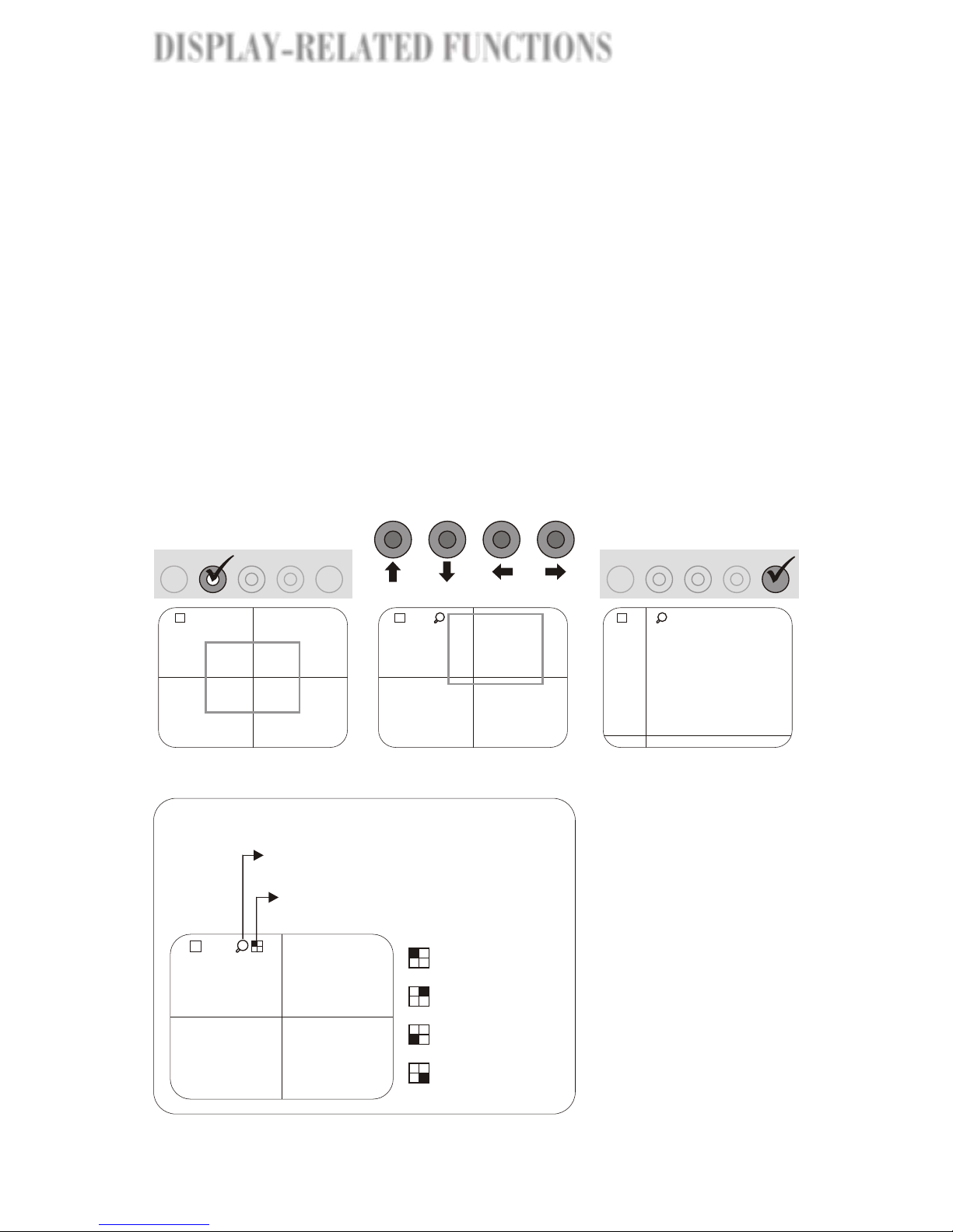
Predefined Zooming
You can use Predefined Zooming to zoom in on a predefined area on the screen.
There are four predefined areas: top-left, top-right, bottom-left, and bottom right
(see the figure below).
Camera 3
L 1234
09/07/2001 14:30:00
Z
Top-left
Top-right
Bottom-left
Bottom-right
Predefined zoomed areas
Z O O M
E N T E R
F R E E Z E P IC T U R E
M O D E
Step 1
Enable the Zoom function
Press the ZOOM button.
The LED in the center of
the ZOOM button is lighted.
Step 2
Enable Predefined
Zooming
Press the SETUP button.
The LED is lighted. The
Predefined Zooming is
initiated by zooming in on
the top-left predefined area.
Step 3
Zoom in on a predefined
area
View the predefined
zoomed areas by pressing
one of the channel buttons.
C H 1
C H 2
C H 3
C H 4
S E T U P
Z O O M
E N T E R
F R E E Z E P IC T U R E
M O D E
C H 1
C H 2
C H 3
C H 4
S E T U P
CH 1
Top-left
Button
CH 2
Top-right
CH 3
Bottom-left
CH 4
Bottom-right
Predefined
Area
Screen
Icon
L 1234
Camera 2 Camera 3
09/07/2001 14:30:00
L 1234
09/07/2001 14:30:00
Z
L 1234
09/07/2001 14:30:00
Z
Pressing the ZOOM button at any time when the zoom
function is enabled will terminate the zoom function.
DISPLAY-RELATED FUNCTIONS
DISPLAY-RELATED FUNCTIONS
DISPLAY-RELATED FUNCTIONS
DISPLAY-RELATED FUNCTIONS
10E-
Englush
Page 16
Software Setup
When the system is not using the
Freeze or Zoom function, pressing
the SETUP button will display the
setup menu on the screen that
allows you to change the display
environment such as the channel
names, and the date and time
displayed on the screen, etc.
CHANNEL NAME
DATE/TIME
DISPLAY MODE
AUTO SWITCH
EXIT
SYSTEM SETUP
SELECT , PUSH ENTER KEY
Cursor Operation
Move the cursor around using the keys
listed below.
CH 1
CH 3
CH 2
ENTER
CH 4
Move the cursor one option
down in the menu lists
Change the setting to one
option up or the character to
the previous character
sequentially
Move the cursor one character
to the right in the sub-menu
Change the setting to one
option down or the character
to the next character
sequentially
Go to the submenu of the
selected option in the main
menu. And save the setting.
CHANNEL NAME
CH1: CAMERA 1CAMERA 1
CH2: CAMERA 2 CAMERA 2
CH3: CAMERA 3CAMERA 3
CH4: CAMERA 4CAMERA 4
You can change the channel
names as desired. The channel
names are displayed on the
bottom of the screen or below
the sub-screens.
DATE/TIME 09 / 06 / 200109 / 06 / 2001
18 : 22 : 5 418 : 22 : 5 4
The time and date displayed on
the screen can be changed here.
Time and date are displayed on
the upper-right corner of the
screen.
DISPLAY MODE
BORDER: WHITEWHITE
BLINK: SEC 1.0 1.0
You can change the color of the
border and how fast the channel
numbers blinks when some
functions are used.
AUTO SWITCH
INTERVAL: SEC0.2 0.2
QUAD MODE: OFFOFF
The interval between a channel
and next in sequence modes can
be set here.
Main Menu Sub-menu Description
MANAGING DISPLAY ENVIRONMENT
MANAGING DISPLAY ENVIRONMENT
11E-
Page 17

Recording
The system starts recording automatically the
second the power is switched on.
When the system is inactive (under neither the
playback nor the OSD mode), pressing the
REC button will start the recording.
The recording always continues from the end
of last recording unless the hard disk is full or
the data in the hard disk has just been cleared.
PLAY/STILL
REV
REC
STOPSLOW
FWD
RESET
CH 1 CH 2
CH 3
CH 4
ZOOMMODE
SETUP
ENTERFREZZE PICTURE
POWER
Front view of the unit
To start the recording
To stop the recording
Recording/Playback Control Buttons
REC
STOP
Press to stop
recording.
Press to start
recording while the
system is inactive.
The circle in the
center of the button is
a LED. It is lighted
when the system is
recording video;
and blinks when the
system is playing
back video.
When there is recording in progress, pressing
the STOP button will stop the recording.
Rewind
Slow
Play/Pause
Stop
Fast Forward
Record
PLAY/STILL
REV
REC
STOP
SLOW
FWD
The six buttons indicated in the figure below control all recording/playback
related functions.
VIDEO RECORDING/PLAYBACK
VIDEO RECORDING/PLAYBACKVIDEO RECORDING/PLAYBACK
12
VIDEO RECORDING/PLAYBACK
E-
Englush
Page 18

Playback
To play back video
In normal motion:
When the system is inactive (neither
recording nor running the OSD), pressing the
PLAY/STILL button will start playing back
the recorded video from the beginning (of the
first recording). If the video has been played
back after the power is turned on, pressing
PLAY/STILL button will play back from
where was left off during the last playback.
In fast forward motion:
When the system is inactive (neither
recording nor running the OSD), pressing the
FWD button will start the fast-forward
playback from the beginning (of the first
recording). If the video has been played back
after the power is turned on, pressing the
button will start the fast-forward playback
from where was left off during the last
playback.
In reverse motion:
When the system is inactive (neither
recording nor running the OSD), pressing the
REV button will start the reverse playback at
the normal speed from the end of the last
recording.
To stop the playback
PLAY/STILL
Press to play
back the
recorded video.
FWD
Press to play
back the video
in fast forward
motion.
REV
Press to play
back the video
in reverse
motion.
STOP
Press to stop
playing back
video.
When the system is playing back video,
pressing the STOP button will stop the
playback.
To pause the playback
When the system is playing back video, fast
forwarding, rewinding or in the normal forward
motion, pressing the PLAY/STILL button will
pause the video. Pressing it again will play
back the video in the normal forward motion
regardless of the original playback type.
PLAY/STILL
Press to pause the
playback regardless
of its motion type.
VIDEO RECORDING/PLAYBACK
13E-
VIDEO RECORDING/PLAYBACK
Page 19

To control the playback motion
In normal playback
Press the FWD button to fast forward the playback. The fast forward goes
even faster each time you press the FWD button again.
Press the REV button to rewind. The rewinding speeds up some more each
time you press the REV button.
Press the SLOW button to play back the video in slow motion. Press it again
to return to the normal playback speed.
Pressing the SLOW button when the video is paused will bring the frozen
picture of the paused video to the Playback Zooming mode (see page E-16).
In fast forward playback
Press the FWD button to speed up the fast forward. The fast forward will go
even faster each time you press the FWD button again.
Press the REV button to slow down the fast forward. Each time you press the
REV button again the fast forward goes slower and eventually turns into
reverse motion (rewinding). Keep pressing the REV button will speed up the
rewinding.
Press the SLOW button to playback the video in the normal speed.
In rewinding at the normal speed
Press the REV button to speed up the rewinding. The rewinding will go even
faster each time you press the REV button again.
Press the FWD button to slow down the rewinding. Each time you press the
FWD button again the rewinding goes slower and eventually turns into fast
forward motion. Keep pressing the FWD button will speed up the fast forward.
Press the SLOW button to playback the video in slow reverse motion. Press it
again to return to the normal rewinding speed. When the rewinding is faster
the normal speed, pressing the SLOW button will playback the video in normal
forward motion.
Playback (Cont'd)
Fast Forward/Rewinding Speed
Assuming the normal playback speed
is 1x, the normal rewinding speed
would be -1X. Each time the FWD button is
pressed (but not held down), you add 1x to
the fast forward speed. Likewise, each time
the REV button is pressed, you add -1x to the
rewinding speed, which means the video
rewinds faster.
Certain speeds are programmed in the FWD
and REV buttons when they are pressed and
held down for more than 1 second. The speed
depends on how long the button is held down:
1 sec. 2 sec.
FWD button 25x 50x
REV button -25x -50x
After 3 seconds the fast
forward/rewinding will
start refreshing with 5
minutes of video apart
between each frame for
three frames; and then
continue with 1 hour
apart.
VIDEO RECORDING/PLAYBACK
VIDEO RECORDING/PLAYBACKVIDEO RECORDING/PLAYBACK
14
VIDEO RECORDING/PLAYBACK
E-
Englush
Page 20

Time Searching
When the system is playing back video, you can choose to view the video
that was recorded during a certain period of time. Press the REC button
while playing back video will display the Time Searching OSD on the screen
as shown in the screen shot on the left hand side below.
Pressing the REV (left arrow) or SLOW (right arrow) button will bring out the
highlight (the screen shot on the right hand side above) that allows you to
set the Present time for Time Searching. After you finish setting the time,
press the REC (OK) button to start searching. The screen will display the
frozen picture of the searched time.
The Start and End time display on the screen remind you of the starting
and ending time of the entire length of video.
If no video was recorded at the starting time set for Time
Searching, the system will find what's closest to the setting
time and display it.
The system's failing to find the accurate starting time may be
caused by the difference between Quad Processor timer and
system timer. Be sure to synchronize both timers to have an
accurate time searching result.
We suggest that you set the system timer (see page E-20)
and Quad Processor timer (see page E-11) when you use
the product for the first time.
(See page? for how to use the buttons on the front panel to control the OSD)
Time Searching Trouble Shooting
Playback (Cont'd)
VIDEO RECORDING/PLAYBACK
15
VIDEO RECORDING/PLAYBACK
E-
Page 21

Playback Zooming
Playback (Cont'd)
When the video is paused (frozen), pressing the SLOW button will bring the
system into the Playback Zooming mode and the system will zoom in on the
upper left corner of the screen and display it in the center of the screen.
Press the SLOW button again to zoom in on the upper right corner of the
screen, press the button again, the lower left corner, and again, the lower
right corner. (See the figure below.)
Paused
SLOW
Zoom 1 Zoom 2
SLOW
Press Press
Zoom 3 Zoom 4
L 1234
09/07/2001 14:30:00
SLOW
Press
SLOW
Press
L 1234
09/07/2001 14:30:00
Paused
SLOW
Press
L 1234
09/07/2001 14:30:00
L 1234
09/07/2001 14:30:00
L 1234
09/07/2001 14:30:00
L 1234
09/07/2001 14:30:00
VIDEO RECORDING/PLAYBACK
VIDEO RECORDING/PLAYBACKVIDEO RECORDING/PLAYBACK
16E-
Englush
VIDEO RECORDING/PLAYBACK
Page 22

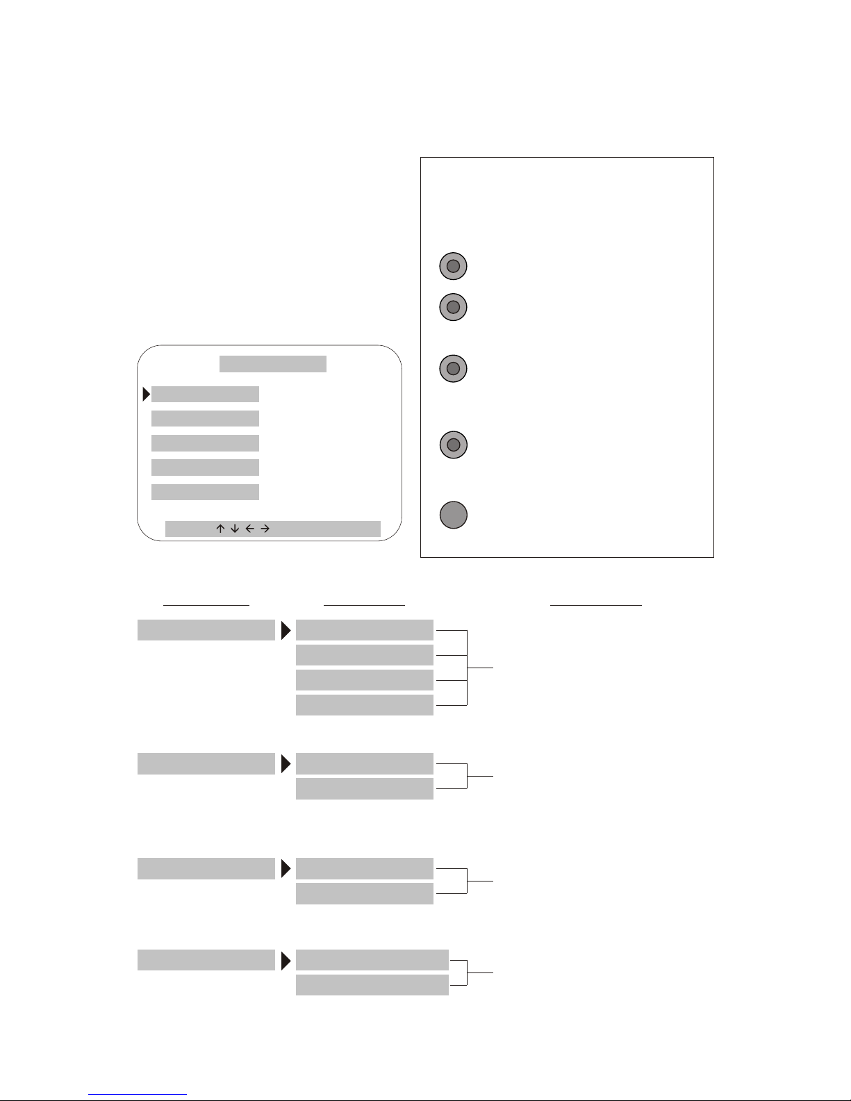
The DVR setup OSD allows you to do recording/playback related settings.
There are five setup categories: File Management, System Timer Setting,
Video Recording, Network, and Language.
The structure of the DVR setup OSD is indicated as below:
How to Open the OSD Menu
1. In order to open the DVR setup OSD, you
need to be sure the system is not
recording (LED off) or playing back video.
If it is, press the STOP button to stop the
playback or recording.
2. Pressing the SLOW button will display
the DVR setup OSD main menu on the
screen as shown in the figuret to the right.
Main Manu Submenu or Setup page Setup page
File Management
Clear Data (Mobile Rack)
Partition (Mobile Rack)
Clear Data (System HD)
Back up (System HD)
System Timer Setting System Timer Setting page
Video Recording Time Lapse
Disk Full
Time Lapse setup page
Overwrite Automatically
Clear Data Manually
Language English
Chinese
Network Network setup page
Operating the OSD
The six buttons on the bottom of the OSD
screen are an analogue of the six playback/
recording buttons on the front panel of the
unit, giving instructions of how to move
about and do settings in the OSD using
those buttons on the unit.
(Main Menu)
PLAY/STILL
REV
REC
STOP
SLOW
FWD
(Front Panel)
PLAY/STILL
REV
REC
STOP
SLOW
FWD
To move the highlight
one item up or left.
To change the setting
value one option down.
To change the setting
value one option up.
To move the highlight
one item down or right.
To quit the current OSD
and go back to the
previous level.
To save the settings.
DVR SETUP OSD
DVR SETUP OSD
E-17
Page 23

File Management
(Main Menu) (File Management Submenu)
To partition Hard Disk in mobile rack
On the File Management submenu select Partition under <HD in Mobile
Rack> and press the REC button, A warning message will then appear:
This will remove all partitions... Hold the REC button down for at least 3
seconds to remove old partitions (if any) and make new partitions.
(File Management Submenu)
New hard disk alert
When you use the system with a
Hard Disk in the mobile rack for
the first time, the system will
show the 'New Hard Disk Found'
alert message on the screen as
the screen shot to the right. You
need to partition the Hard Disk
as instructed above.
The File Management submenu allows you to manage the recorded data on
your hard disk. The settings you can do under the File Management submenu
is described as follows.
DVR SETUP OSD
DVR SETUP OSD
DVR SETUP OSD
DVR SETUP OSD
18E-
Englush
Page 24

Backing up Data
Select "Backup" under <System HD> and press the REC button. A warning
message will then appear: This will remove all data from your HARD
Disk in mobile rack and make a backup copy... Holding the REC button
down to perform the command. (See the figure below.)
To erase data from system Hard Disk
Select Clear Data under < System HD > and press the REC button. A
warning message will then appear: This will erase all data... Holding the
REC button down to perform the command. (See the figure below.)
To erase data from mobile rack
Select Clear Data under <HD in Mobile Rack> and press the REC button.
A warning message will then appear: This will erase all data... Holding
down the button to perform the command. (See the figure below.)
(File Management Submenu)
DVR SETUP OSD
DVR SETUP OSD
E-19
Page 25

System Timer Setting
The System Timer Setting submenu allows you to set the time for your DVR
system.
(Main Menu) (System Timer Setting)
Synchronizing the Timers
Select System Timer Setting on the main menu and press the REC button
(OK). The setup page will then appear (see the figure above). Pressing the
REV (left arrow) or SLOW (right arrow) button will freeze the timer and
highlight the year setting of the timer (see the figure below). You can now
start changing the timer setup.
Apart from the system timer, the Quad Processor also has a timer.
We suggest that you synchronize these two timers before you start
using the playback/recording related functions. Refer to page E-11
for how to set the timer for Quad Processor.
The synchronization of the two timers is crucial for running Time
Searching (see page E-15).
The time displayed on the screen is from the Quad Processor.
20
DVR SETUP OSD
DVR SETUP OSD
DVR SETUP OSD
DVR SETUP OSD
E-
Englush
Page 26

Video Recording
The System Timer Setting allows you to set the time for your DVR system.
Select Video Recording on the main menu and press the REC button (OK). A
submenu will then be displayed on the screen as shown in the figure below.
Select Time Lapse on the Video Recording menu and press the REC
button (OK). The Time Lapse setup OSD will then appear on the screen
(see the figure below). Highlight a setting as desired and then press the
REC button (OK) to save the new setting.
The default setting for Time Lapse is 15 fps for NTSC, and 13 fps for PAL..
(Main Menu) (Video Recording submenu)
Setting time lapse for recording
(Video Recording submenu)
Under NTSC system
Under PAL system
DVR SETUP OSD
DVR SETUP OSD
E-21
Page 27

Video Recording (Cont'd)
When Hard Disk is full......
The Disk Full setup OSD allows you to determine the system's action when
the Hard Disk is full.
Selecting Overwrite
Automatically and press the REC
button (OK), the system will record
new video over old video when the
Hard Disk is full.
(Video Recording submenu)
Select Clean data manually and
press the REC button (OK). By
doing this setting, the system will
display an alert message : The
Hard Disk is full and unable to
record any more data on the
screen, when the hard disk is full
and the system is unable to
continue the recording (see the
bottom figure to the right). You
need to go to the File Management
OSD submenu and run the Clear
Data command to clear the Hard
Disk so you can continue recording.
22
DVR SETUP OSD
DVR SETUP OSD
DVR SETUP OSD
DVR SETUP OSD
E-
Englush
Page 28

Network
The Network setup OSD allows you to setup for network connection.
Select Network on the main menu and press the REC button (OK). The
Network OSD will then appear on the screen as shown in the figure below.
(Main Menu) (Network setup OSD)
Pressing the REV (left arrow) or SLOW (right arrow) button will bring out the
highlight (see the figure below) that allows you to change the Network setup.
Language
The Language setup OSD allows you to choose your system language either
as English or Chinese.
Select Language on the main menu and press the REC button (OK). The
Language OSD will then appear on the screen as shown in the figure below.
(Main Menu) (Language Setup OSD)
DVR SETUP OSD
DVR SETUP OSD
E-23
Page 29

Internet Access
For the video from the monitored sites to be viewed on your computer browser,
first you need to locate LTR-3100 at http://172.16.0.57:8080 (LTR-3100's
temporary IP) set by the manufacturer while your computer is connected to
the LTR-3100 through a hub. Then finish the settings instructed below.
Signing in the Suveillance Site
Once you log on http://172.16.0.57:8080, the site will prompt you to enter the
user name and password as shown in the screen shot below.
Defaults:
User Name: root
Password: root
After entering the user
name and password, the
browser will open the
surveillance home page as
shown in the screen shot
to the left.
Home Page
Setting connection speed
On the surveillance home page,
there are 5 speed buttons on the
left hand side of the screen.
Please see the table to choose a
speed that suits your type of
connection.
Button Speed Connection Type
Speed 1 0.2 Local LAN; Intranet
Speed 2 2 ADSL
Speed 3 5 ADSL
Speed 4 7 ADSL or Modem
Speed 5 10 Modem
*The default speed is 0.2
REMOTE SURVEILLANCE
REMOTE SURVEILLANCE
REMOTE SURVEILLANCE
REMOTE SURVEILLANCE
24E-
Englush
Page 30

Set LTR-3100's IP
1. Click on "MENU'
on the left hand
side of the
Security DVR
home page. The
browser will go
to the menu
page as shown
in the figure to
the right.
2. Click on "Set up
Network". Then
the IP setup
page will appear
as in the second
figure to the
right.
3. Enter the data
provided by
your Internet
service
provider (ISP).
ThenClick on
"Set up
Network".
Then Click
"OK".
You need to set LTR-3100's IP as assigned by your
Internet service provider (ISP) to locate the
surveillance website on the internet.
REMOTE SURVEILLANCE
REMOTE SURVEILLANCE
25E-
Page 31

Changing User Name and Password
You might want to replace the default user name and password. To set a new
user name and password, click "Set Password" on the menu page. The
browser will go to the page for setting such settings. After entering your new
username and password, click "OK".
Now You can view the surveillanced video
as displayed on the TV monitor by log on
the Security DVR web page at the IP you
just set.
REMOTE SURVEILLANCE
REMOTE SURVEILLANCE
REMOTE SURVEILLANCE
REMOTE SURVEILLANCE
26E-
Englush
Page 32

27E-
This device complies with Part 15 of the FCC Rules. Operation is subject to
the following two conditions:
! This device may not cause harmful interference.
! This device must accept any interference received, including interference
that may cause undesired operation.
This equipment has been tested and found to comply with the limits for a
Class B digital device pursuant to Part 15 of FCC Rules. These limits are
designed to provide reasonable protection against harmful interference in a
residential installation. This equipment generates, uses and can radiate radio
frequency energy and, if not installed and used in accordance with the
instructions, may cause harmful interference to radio communications.
However, there is no guarantee that interference will not occur in a particular
installation. If this equipment does cause harmful interference to radio or
television reception, which can be determined by turning the equipment off
and on, the user is encouraged to try to correct the interference by one or
more of the following measures:
! Reorient or relocate the receiving antenna.
! Increase the separation between the equipment and receiver.
! Connect the equipment into an outlet on a circuit different from that to which
the receiver is connected.
! Consult the dealer or an experienced radio/TV technician for help.
! Shielded interface cables must be used in order to comply with emission
limits. Changes or modifications not expressly approved by the party
responsible for compliance could void the user's authority to operate the
equipment.
FCC STATEMENTS
FCC STATEMENTS
 Loading...