

Page 1

Network Surveillance Camera
NSC 3615 / NSC 3621
User Manual
Page 2

Int
l Head
Date Version Description Author
2007.01.24 2.0.0 First release IPCAM team
No part of this document may be copied or reproduced in any form or by any means without the prior written consent
of Leadtek Research Inc.
Leadtek makes no warranties with respect to this documentation and disclaims any implied warranties of
merchantability, quality, or fitness for any particular purpose. The information in this document is subject to change
without notice. Leadtek reserves the right to make revisions to this publication without obligation to notify any person
or entity of any such changes.
Trademarks or brand names mentioned herein are trademarks or registered trademarks of their respective owners.
Copyright 2006 Leadtek Research Inc. All rights reserved
ernationa
18th Fl., 166, Chien-Yi Rd., Chung Ho, Taipei Hsien, Taiwan (235)
Phone: +886 (0)2 8226 5800 Fax: +886 (0)2 8226 5801
http://www.leadtek.com.tw
For business
ipcamsales@leadtek.com.tw
For Technical Services
ipcamfae@leadtek.com.tw
quarters
Please also visit the following link for the latest news about our video surveillance products .
http://www.leadtek.com.tw/eng/
- Page 2 -
Page 3

Contents
Package Contents............................................... 5
Introduction.......................................................... 8
Connections and Functions........................... 11
System Requirement.......................................14
Hardware Installation..................................... 15
Software Installation ...................................... 16
Administrating from Webs............................ 27
Login...................................................................................................................27
Download ActiveX Control .................................................................28
Overlook....................................................................................................29
System...............................................................................................................30
System.......................................................................................................30
SIP...............................................................................................................31
Others........................................................................................................32
DIDO...........................................................................................................33
Network Control.............................................................................................34
IP .................................................................................................................34
FTP ..............................................................................................................35
SMTP...........................................................................................................36
DDNS..........................................................................................................37
RTP Port ....................................................................................................38
Camera..............................................................................................................39
Camera......................................................................................................39
Encode Type............................................................................................40
User Management Control.........................................................................41
Set...............................................................................................................41
System Log......................................................................................................42
Restore to factory default..........................................................................43
How to use SMC ?............................................44
Install Surveillance Management Center.............................................44
Launching the SMC / Scheduler..............................................................48
Finding Surveillance Cameras..................................................................49
SCAN..........................................................................................................50
MODIFY......................................................................................................52
APPLY.........................................................................................................54
BACK...........................................................................................................55
- Page 3 -
Page 4

ADD.............................................................................................................56
Basic Operation..............................................................................................59
Recording..................................................................................................59
Snapshot...................................................................................................60
Send Voice...............................................................................................60
Change Layout .......................................................................................61
Full Screen...............................................................................................61
Add Camera.............................................................................................61
File Viewer................................................................................................62
Advanced Operation.....................................................................................65
Camera......................................................................................................65
General Setting......................................................................................67
Advance Setting.....................................................................................68
PTZ..............................................................................................................75
Using Camera with a Router ........................ 82
Appendix .............................................................. 88
Installing Scan Utility...................................................................................88
Firmware Upgrade ........................................................................................92
Frequently Asked Questions......................... 94
Network Configuration ................................................................................94
Surveillance Management Center...........................................................97
Version Information .............................................................................98
SIP Configuration................................................................................100
Motion Detection..................................................................................101
Video Quality Setting.........................................................................104
Bandwidth Usage.................................................................................112
Surveillance Camera..................................................................................113
Dynamic Domain Name Service....................................................114
Factory Default Setting.....................................................................116
Version Information ...........................................................................117
Video Decoder Plug-in.......................................................................118
ActiveX Control Download ...............................................................118
Remove Old ActiveX Controls.........................................................120
Network Settings.................................................................................124
Bandwidth Configuration..................................................................124
Web Configuration..............................................................................125
SIP Connection Mode.........................................................................125
Codec Select..........................................................................................126
- Page 4 -
Page 5
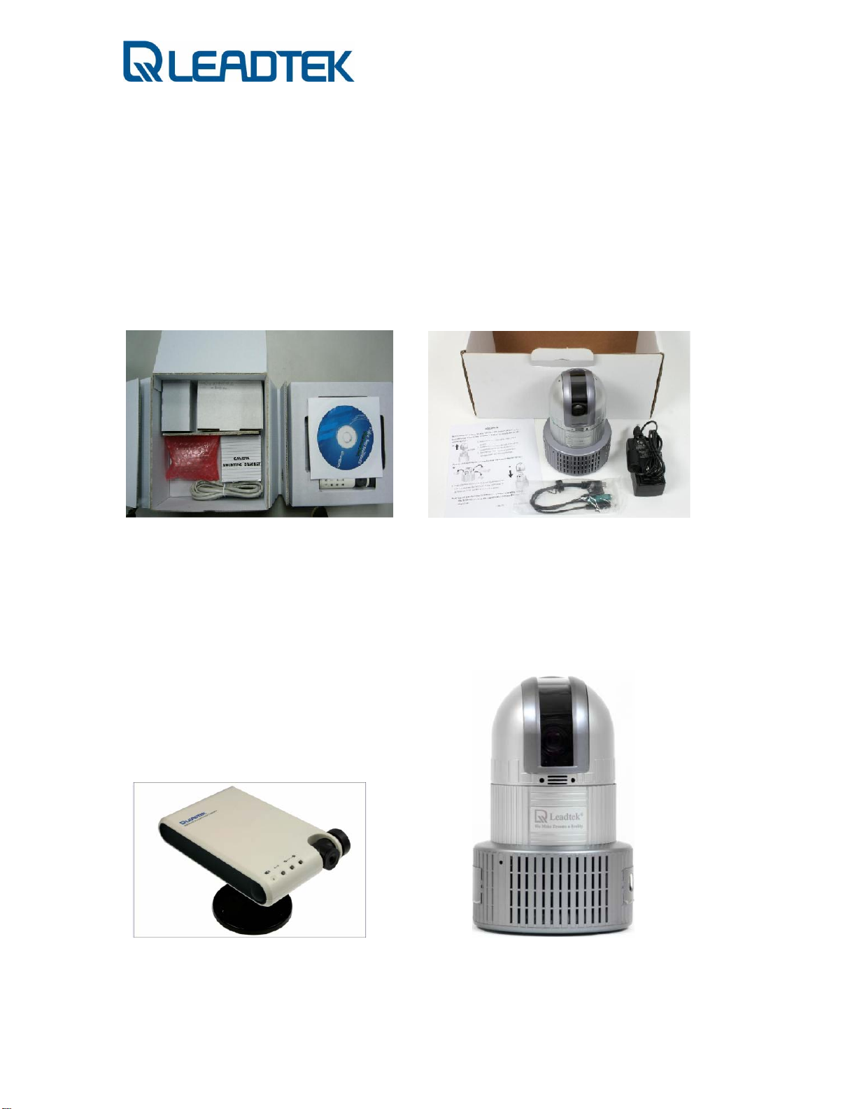
Package Contents
Contents
- NSC3615- -NSC3621-
Leadtek Surveillance Camera
- NSC3615- -NSC3621-
- Page 5 -
Page 6
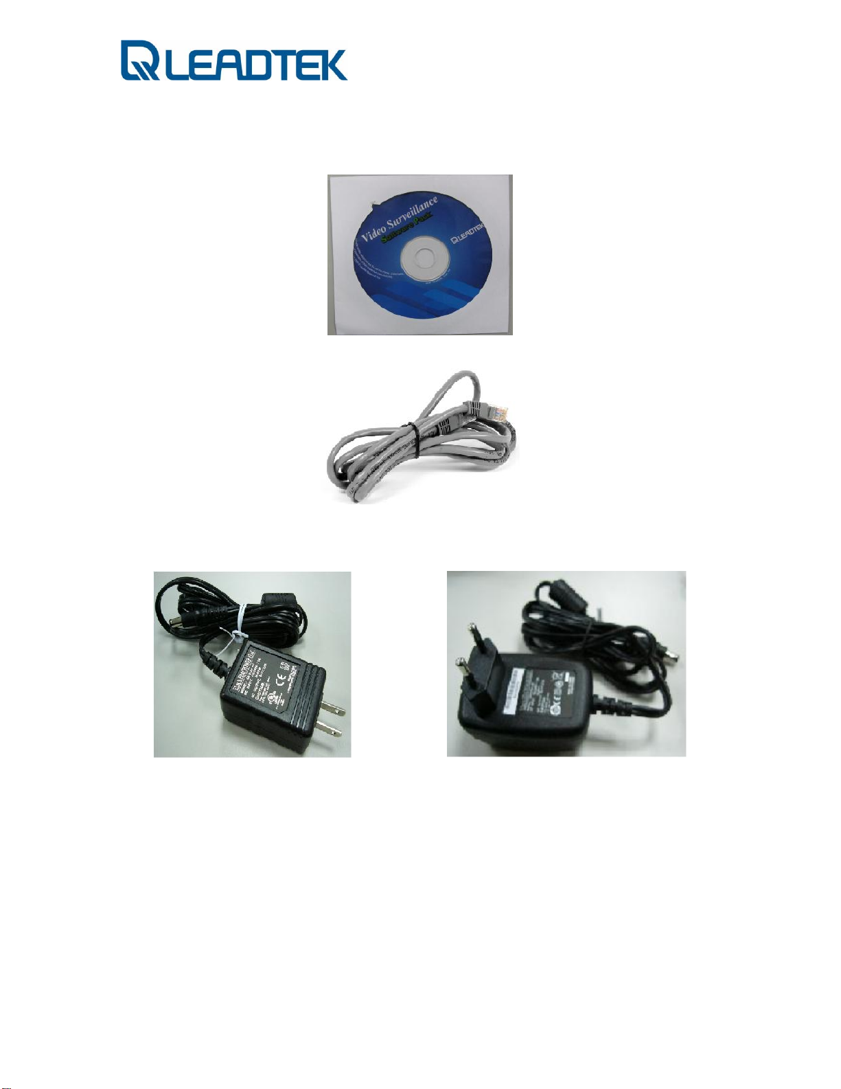
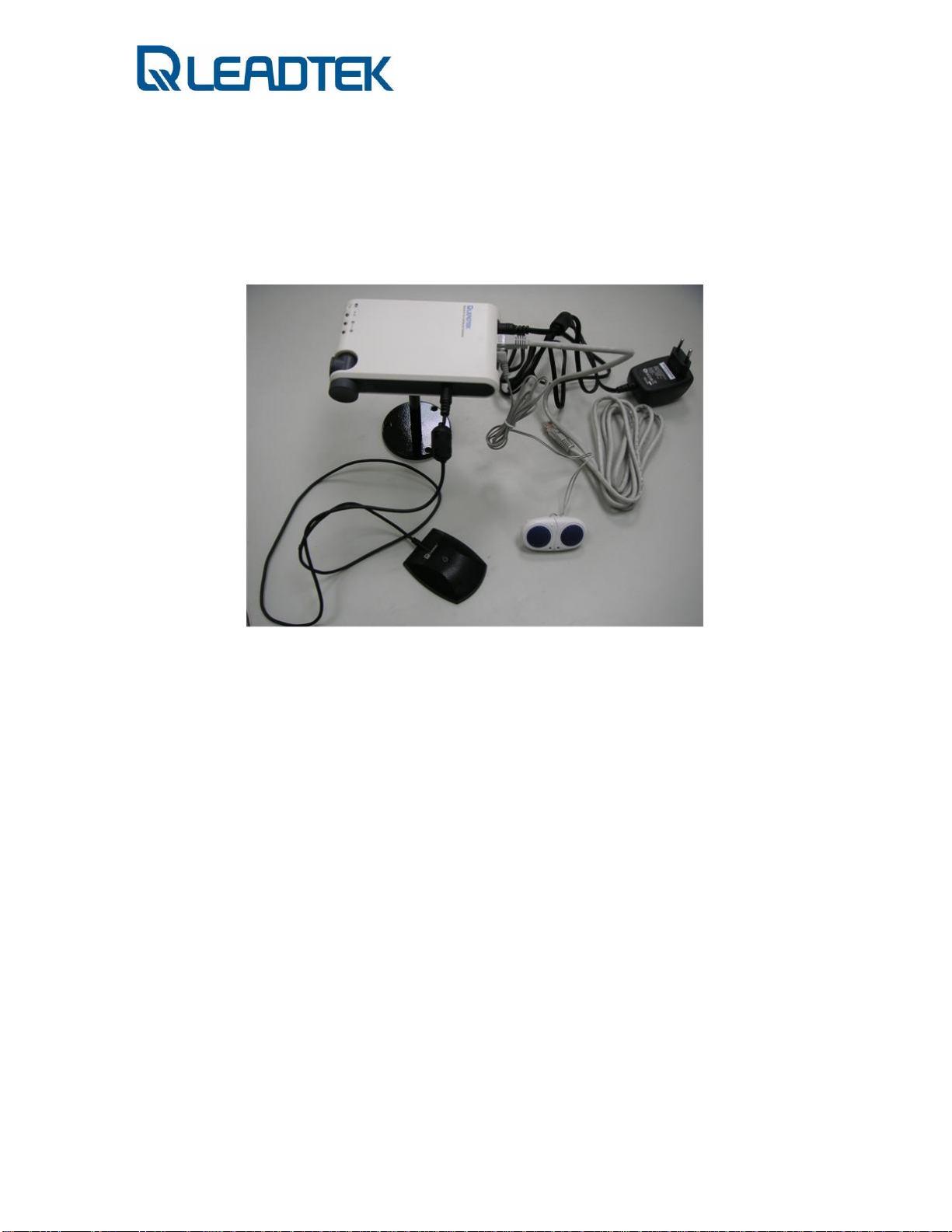
Accessories
Software CD:
Ethernet cable:
Power Adaptor:
-NSC3615- / -NSC3621
-NSC3615-
- Page 6 -
Page 7
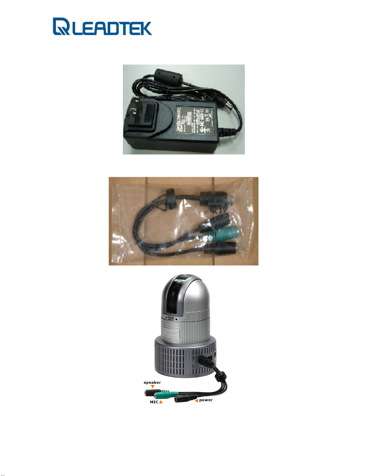
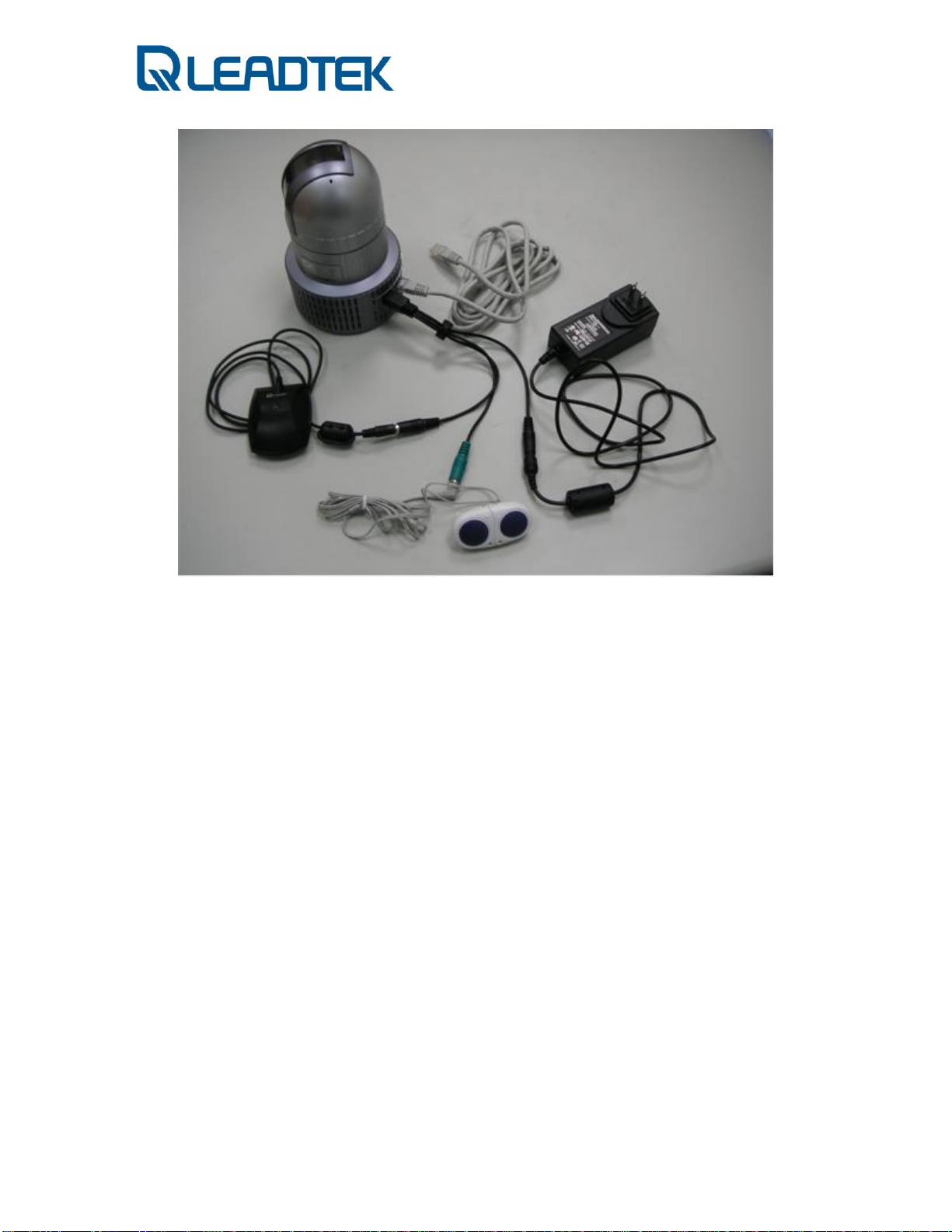
SPK-MIC-PWR 3-in-1 cable
-NSC3621-
-NSC3621-
- Page 7 -
Page 8
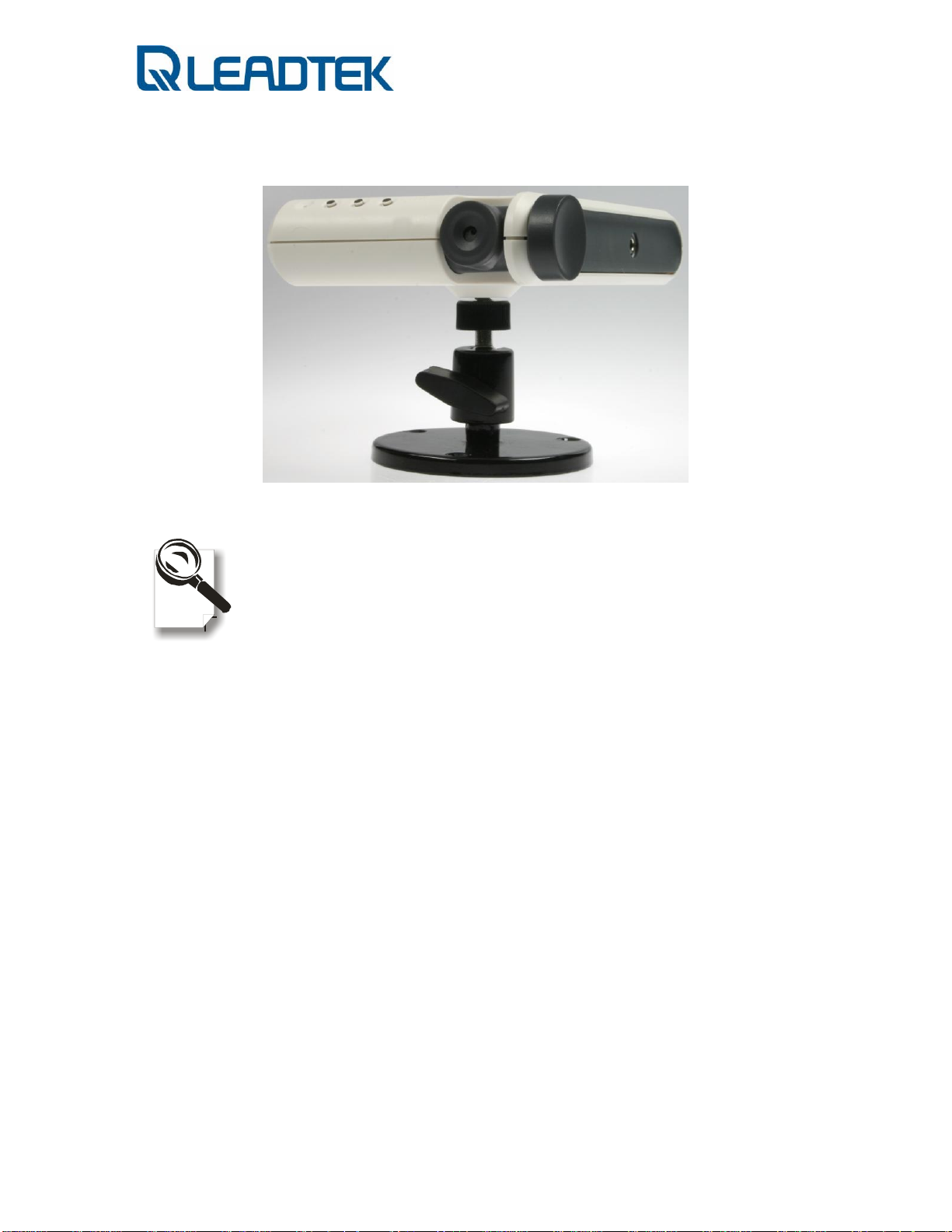
Mounting Rack:
Please unpack the product package with caution; inspect
the Items closely. If you find any damaged item, please
contact your local distributor immediately. Also, please keep
the box and packing material for future use in the event of
future shipments.
-NSC3615-
Introduction
High-quality, high efficiency video & audio transmission via IP network
The network surveillance camera allows you to view live video over internet. Your
control center can be set up anywhere with internet access without being restricted
by locations. Surveillance video is processed by the most up-to date compression
technology and transmitted in MPEG-4 compression format, whose transmission
efficiency and video quality remain uncompromised by the network, minimizing the
lagging of live surveillance video. In addition, wireless LAN is also supported. The
wireless model makes the network usage more handy without the hassle of cable
installation.
Great usability in every surveillance aspect
The network surveillance camera’s ease of use begins with its web-based user
- Page 8 -
Page 9

interface, using Microsoft Internet Explorer to browse the live video or the provided
Windows client Surveillance Management Center(SMC) that offers many additional
benefits: its user interface can display video up to 9 camera servers at the same
time. Recording can also be done simultaneously and you can use it to view recorded
video from the archive and backup your recorded file with audio.
Unparalleled surveillance functions where nothing slips through your watch
The network surveillance camera’s motion detection function sends out the alarm
when any movement of any object occurring on the scene is detected, which makes
it ideal for home and after-hour facility security. 16 preset positions can be
programmed and the auto-cruise function will make the tour accordingly as if you
were taking the patrol rounds in person.
You can also program the cameras to take snapshots or record video when the alarm
is triggered by the event. These snapshots can be transmitted via FTP or email.
Event recording is done by a client PC on the network as the camera sends snapshot
in JPEG format as part of the responses to the triggered event.
Optional centralized management software for large scale surveillance
services
The software suite performs as a central control station on a client PC that controls,
manages, and monitors up to 9 network surveillance camera server units over the
network at the same time. You can talk to your surveillance camera just by a click on
the managed camera to start 2-way audio conversation. The flexible and diversified
SMC offer you handy surveillance solution on Windows platform.
- Page 9 -
Page 10

Key Features
Surveillance Camera NSC3615 / NSC3621
9 Compact color CMOS / CCD camera
9 Manual / Auto Pan and Tilt function s (Specified models)
9 MPEG-4 / H.263 video and G.711 audio compression
9 Internet connection compatible with Ethernet
9 Support audiovisual transmission and recording
9 A client viewer is able to simultaneously access multiple cameras loc ated at
Bundled Windows Client Surveillance and Management Center
Display
Resolution H.263(CIF , QCIF), MPEG-4(D1, VGA, QVGA, CIF, QCIF)
Image Quality 28 level
Channel 1/4/9 (with multiple camera connections)
Connection Indication Video, Audio and Recording
Caption Camera number, IP Address, Frame Per Second
Easy Recorder/Player
Instant record and playback video manually
Camera Operation
Camera Connection Up to 9 cameras
Camera Scan Search cameras in network
Camera Configuration Network / Video parameters
Event Record Setting
Mode Manual / Event / Scheduler
different sites
9 Built-in Web server for remote surveillance on network
9 Complete remote surveillance and management PC software
- Page 10 -
Page 11
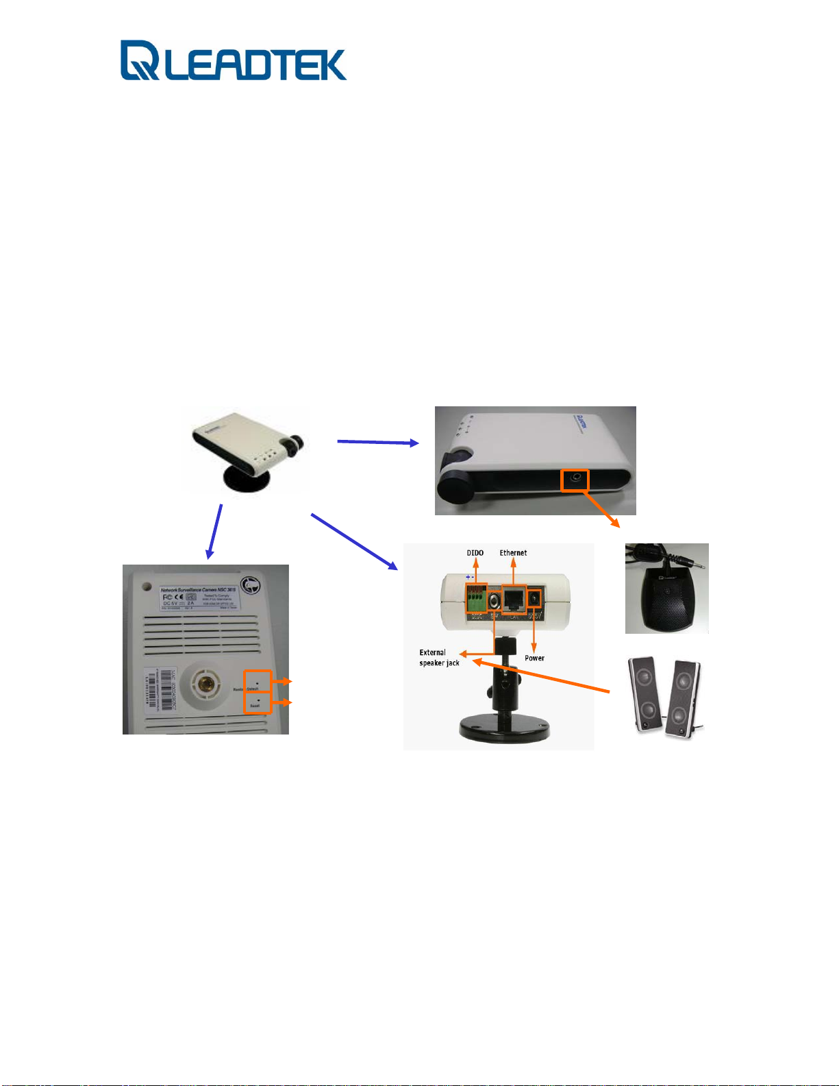
Connections and Functions
Both NSC3615 / NSC3621 equip with 1DI / 1DO connector and PC compatible mono
microphone and speaker. You can also find 2 pinholes (NSC3615:rear view /
NSC3621: back side view of bottom) on surveillance camera. One is Factory
Default and the other one is Reset. Factor y De fa ult brings all camera setting to
factory default setting and Reset triggers a warm system reboot when the pinhole is
pushed by a needle for 2 seconds(and release afterwards).
- NSC3615 -
External MIC
Factory Default
Reset
- Page 11 -
Page 12
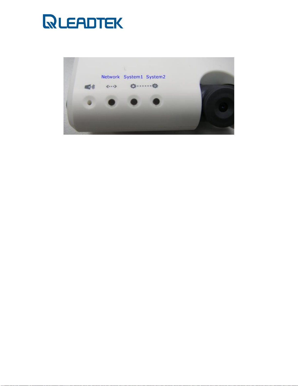
LED Indication
Network LED : BLUE
- OFF : network link down or service unavailable
- ON : network link is up
- Blinking : in/out traffic on going
System 1 LED : YELLOW
- No RTP packet traffic
- RTP received from remote peer (periodic flashing, 0.5 second on, 0.5 second off)
System 2 LED :YELLOW
- OFF : Do not register to SIP server
- Blinking : 4 times per second
- ON : register to SIP server OK
DIDO Connector
The first pinhole pair is for DI connectors and second one is for DO device connectors.
Beware of the polarity of DI device(+ :first pinhole on the leftist side, - :2nd pinhole
from the left, both are for DI device connectors). You don’t need to care about
polarity for DO device since there is a relay equipped on those 2 pinholes
connections (from right hand side). The hardware specification of DI device is as the
following. Connect customer-tailored DIDO device with care and make sure devices
won’t overload surveillance camera’s DIDO interface.
DI : 0 ~ 12V(with 5V logic trigger) / 20 mA(minimum)
DO: 30VDC / 1A
- Page 12 -
Page 13
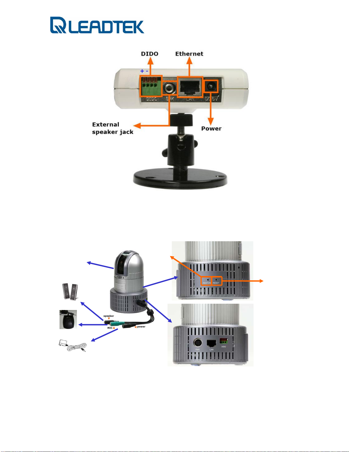
- NSC3621 -
10x optical / 10 digital CCD
DIDO Connector
Factory Default
- Page 13 -
Warm Reboot
_
+
Page 14
Same as NSC3615 DIDO interface.
DI : 0 ~ 12V(with 5V logic trigger) / 20 mA(minimum)
DO: 30VDC / 1A
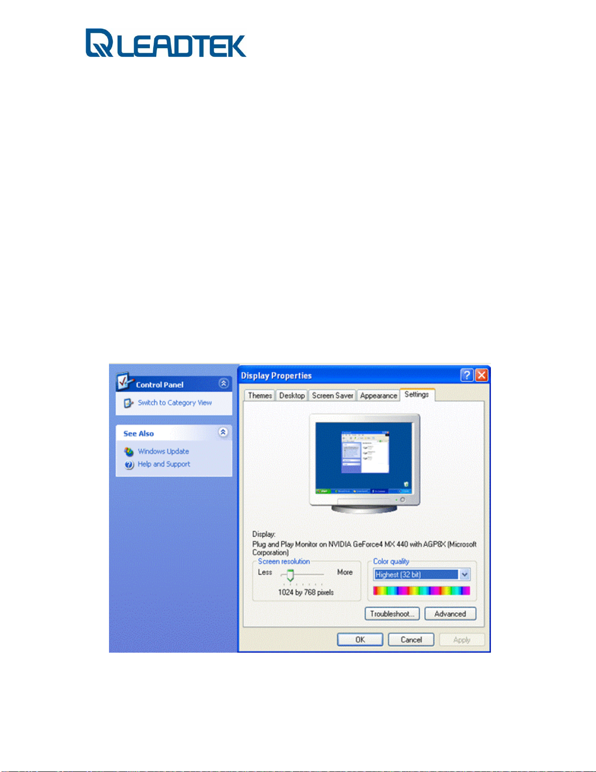
System Requirement
Before you give surveillance camera a shot, please check setting of your notebook /
PC and see if following requirement is proper.
z Windows XP with service pack 2 installed or DirectX 9.0 installed
z Best Screen Resolution : 1024x768
z Color Quality : full color (32 bit)
- Page 14 -
Page 15
Hardware Installation
- NSC3615 -
-NSC3621-
- Page 15 -
Page 16
Software Installation
Follow the procedures describe bellows to do a quick installation setup / test.
1. Device Connection:
Connect your surveillance camera to PC (NSC3621 is taken as an example)
i) Use crossover ethernet cable:
- Page 16 -
Page 17
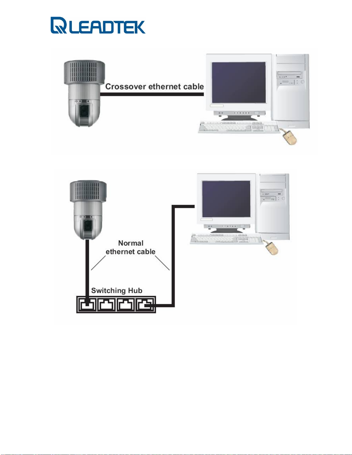
ii) Connect devices with ethernet hub / switch (normal RJ-45 cable)
2. Configure your PC to the same subnet segment of surveillance camera.
i) The camera’s default IP is 192.168.0.100. We need to change our PC’s network
setting first in order to connect to the camera.
PS: if you don’t know how to reset surveillance camera to factory default, please
refer to Factory Default Setting section of Appendix FAQ part.
- Page 17 -
Page 18
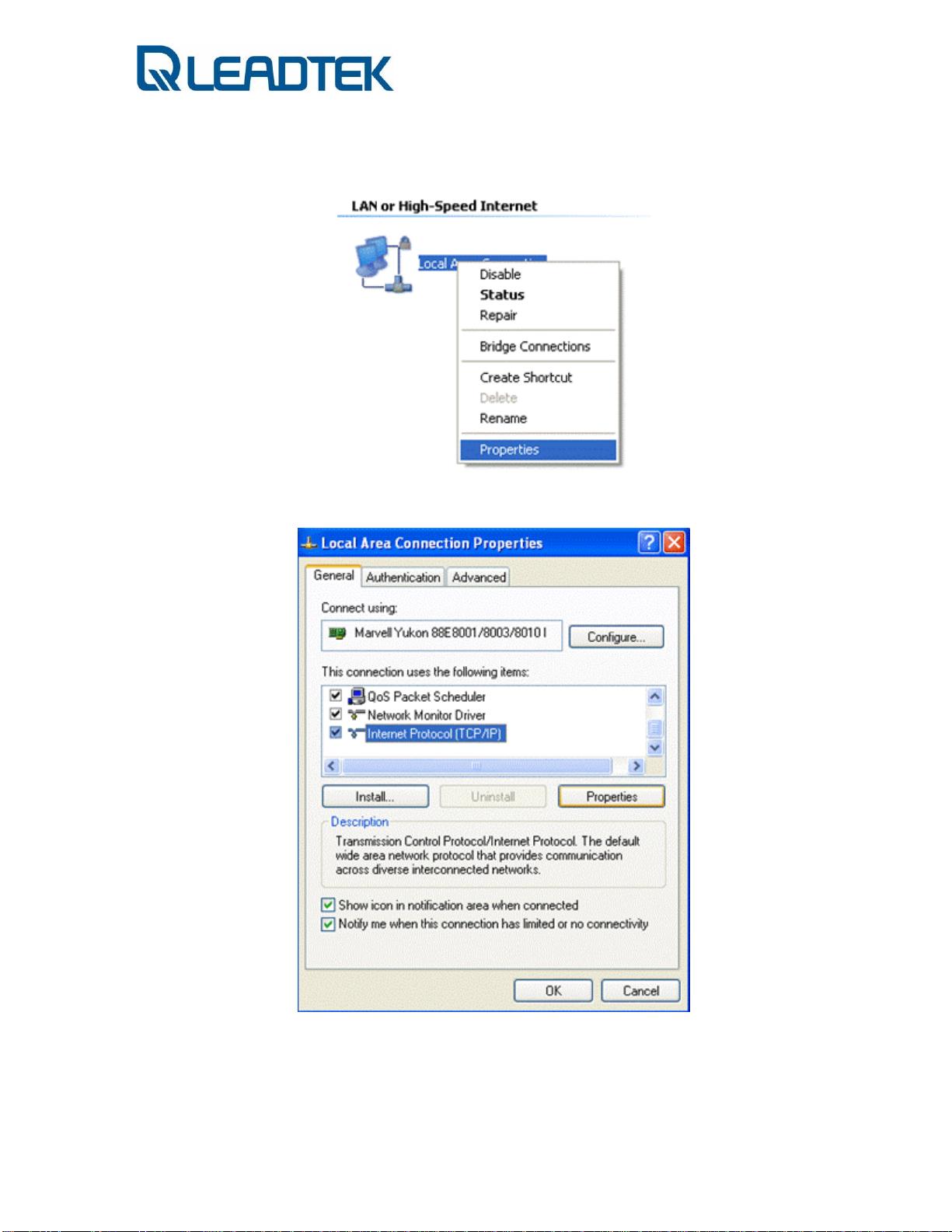
ii) Clicks windows Control PanelÆ Network Connections Æ Local Area
Connection, click mouse right button and then click Properties
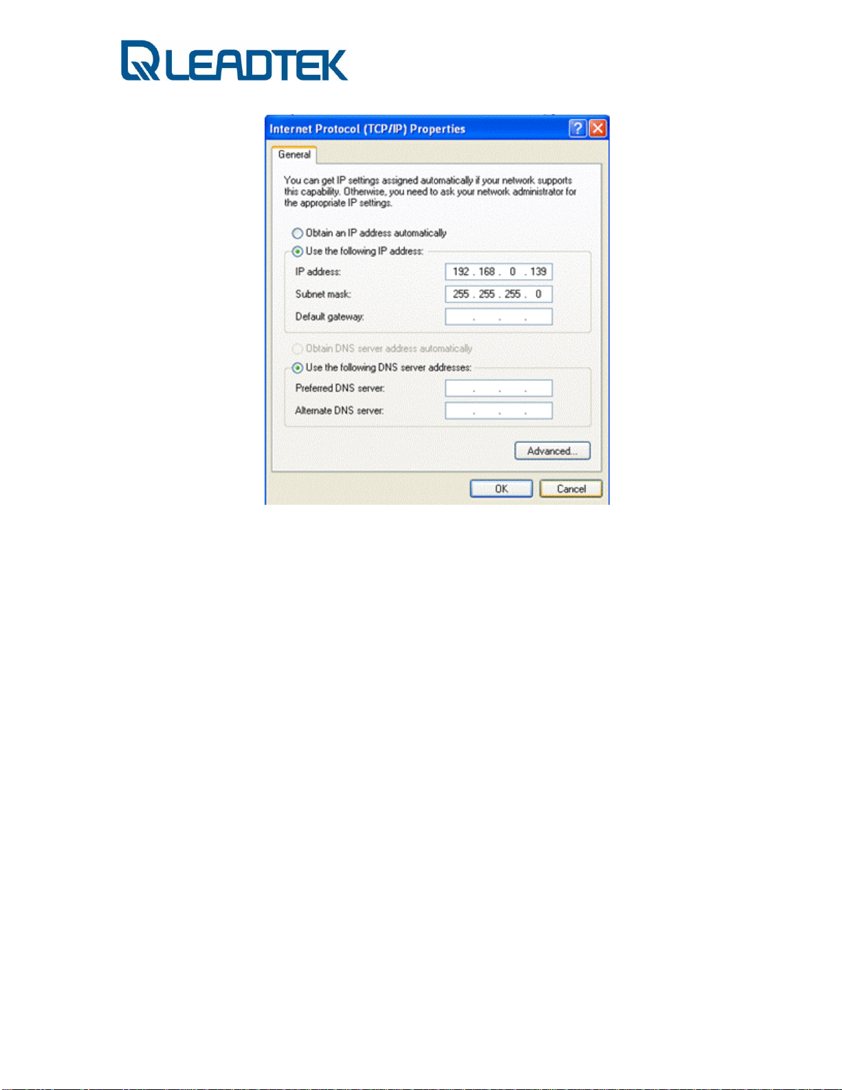
iii) Chooses Internet Protocol (TCP/IP), and then click Properties
iv) Chooses Use the following IP addresses, field, and input IP address with
192.168.0.139, subnet mask with 255.255.255.0, and then click OK.
- Page 18 -
Page 19
v) Verify the on-line status of your surveillance camera. Please follow the procedure
bellows
a) Start ProgramÆ Accessories Æ Command Prompt .A DOS
command shell screen will appear and shows "C:\>".
b) Type ipconfig and press Enter.
c) check if you can get the response from surveillance camera.
- Page 19 -
Page 20
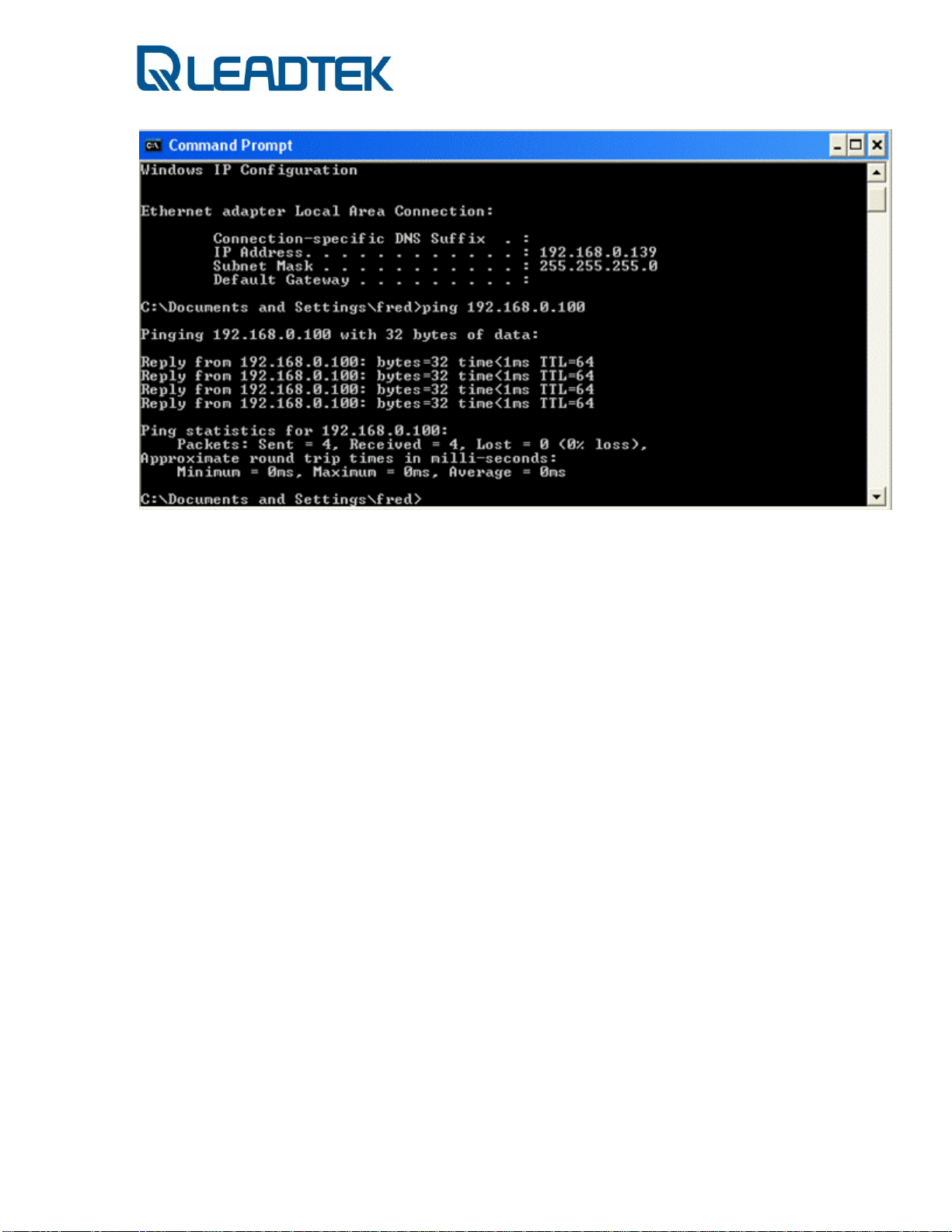
d) Type ping 192.168.0.100 and press Enter. If the screen shows
Reply from 192.168.0.100... it means the hardware installation is
complete.
3. Connect to camera
i) Launches Microsoft Internet Explorer and type URL:
then you shall see the home page like bellows.
http://192.168.0.100,
- Page 20 -
Page 21

ii) The default username/ password is admin / admin, after you login to web
you can get the video and find the system version on the lower-left corner
For the very first time, IE will ask for user to download a video / audio decoder (a.k.a.
ActiveX control) plug-in. Beware of the reminding message on upper-left corner of IE.
Right click on the warning message and allow the plug-in to be installed in your PC.
- Page 21 -
Page 22
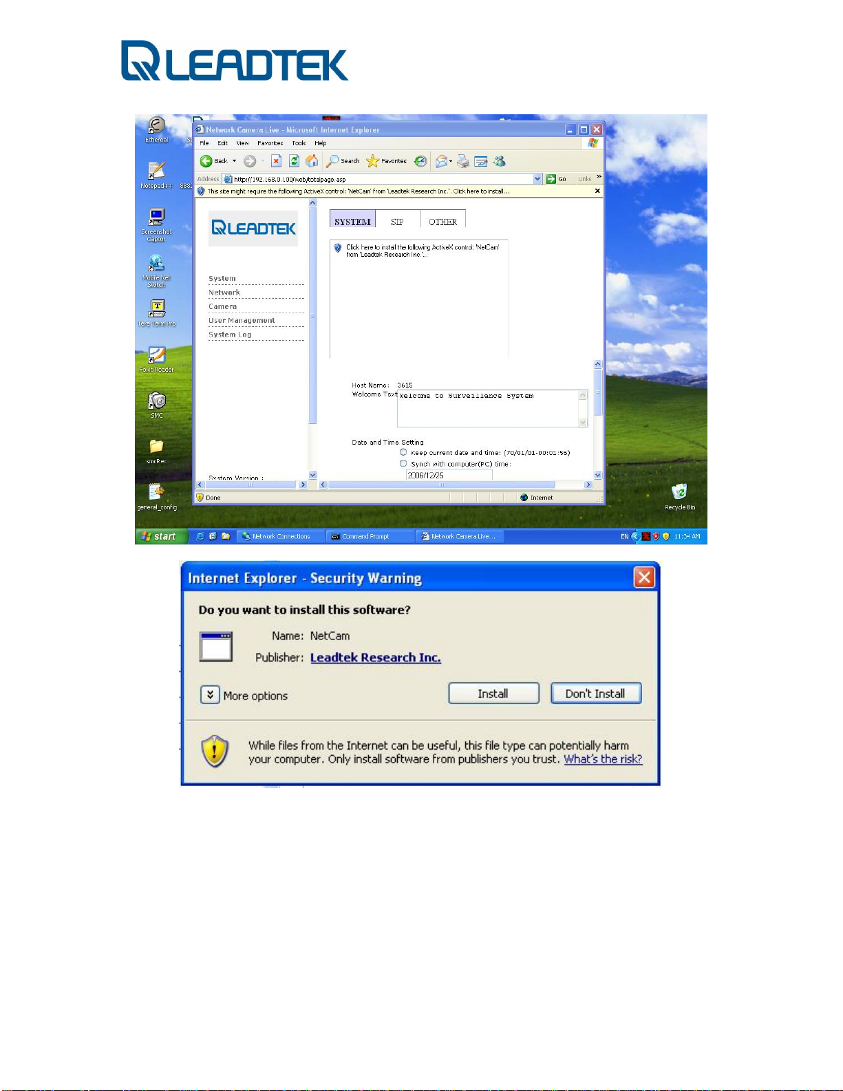
Click the Install button to start installation of decoder plug-in. The live video will be
displayed on IE after the plug-in automatically installed.
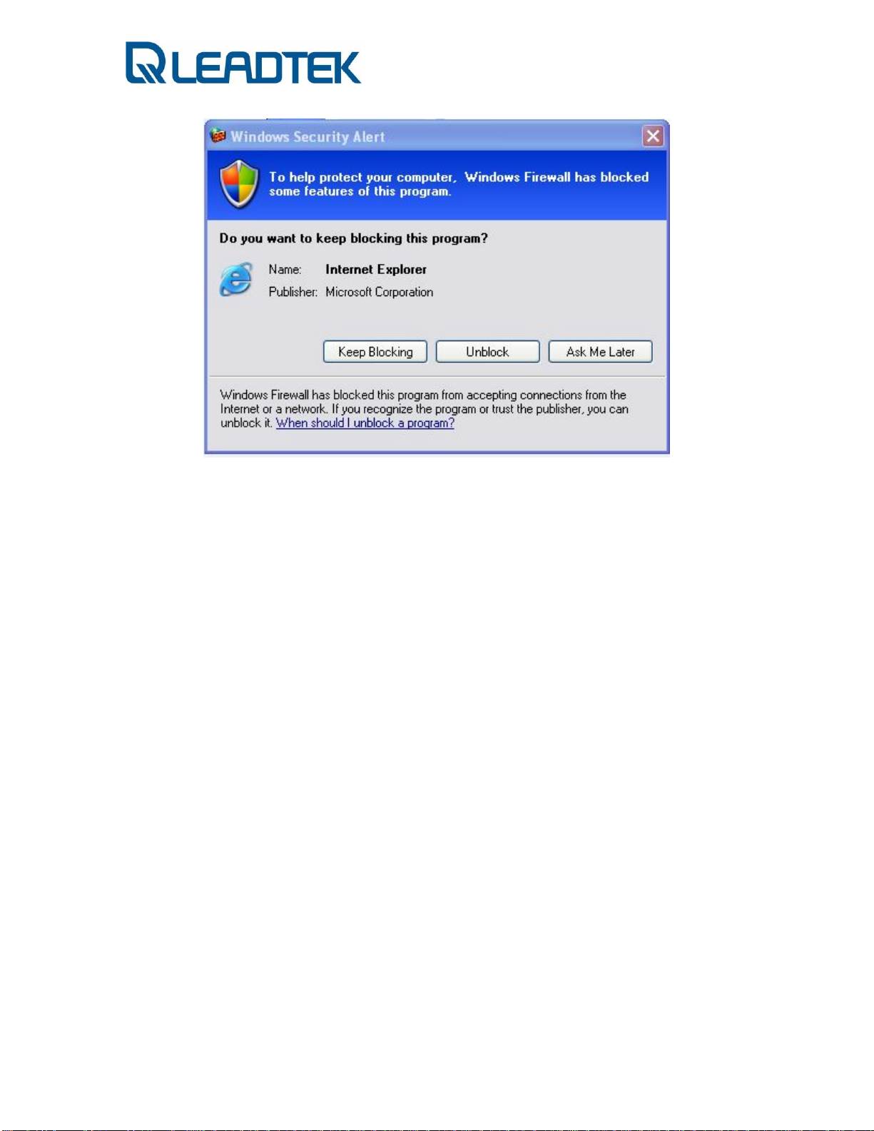
In some case, your local PC may turn on the firewall option and th e following
warning message will pop up. Remember to click Unblock to allow the in-coming
packet and avoid firewall protection.
- Page 22 -
Page 23
- Page 23 -
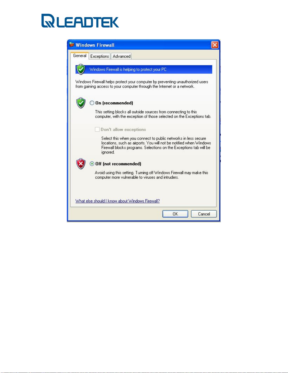
Page 24
Note: In order to turn off the firewall protection, you can refer to Control Panel Æ
Windows Firewall Æ General and turn off the Windows Firewall and permit the in-
coming network packets (audio or video media packets)
- Page 24 -
Page 25
Otherwise, you can discriminately allow specific application and automatically
unblock the firewall protection.
- Page 25 -
Page 26
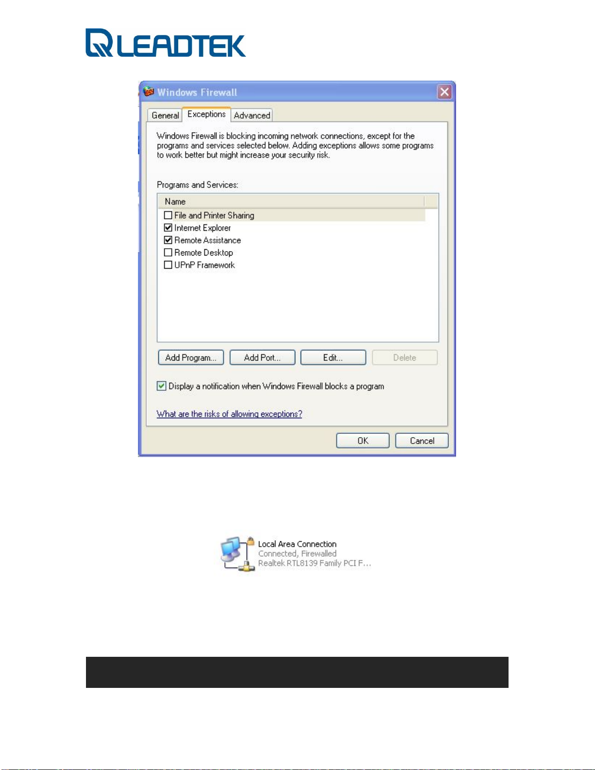
You can check current firewall protection option of your network setting. If the
network connection icon comes with a lock sign, that means the network interface is
firewall protected by Windows Firewall.
Administrating from Webs
- Page 26 -
Page 27

Administra ting from Webs
Login
ach surveillance camera includes a web interface system. As long as you know
the camera’s IP, you can launch IE and access the camera’s IP. Logon to the web
E
server and the following login screen will appear:
In above screen, user name and password are required for user authentication. The
factory default setting is admin. Please enter admin in user name field and admin
in password field, and then press Login button to enter the system, the appearing
screen will show in the next page.
Note : The default IP address of IPCAM is 192.168.0.100 .
- Page 27 -
Page 28
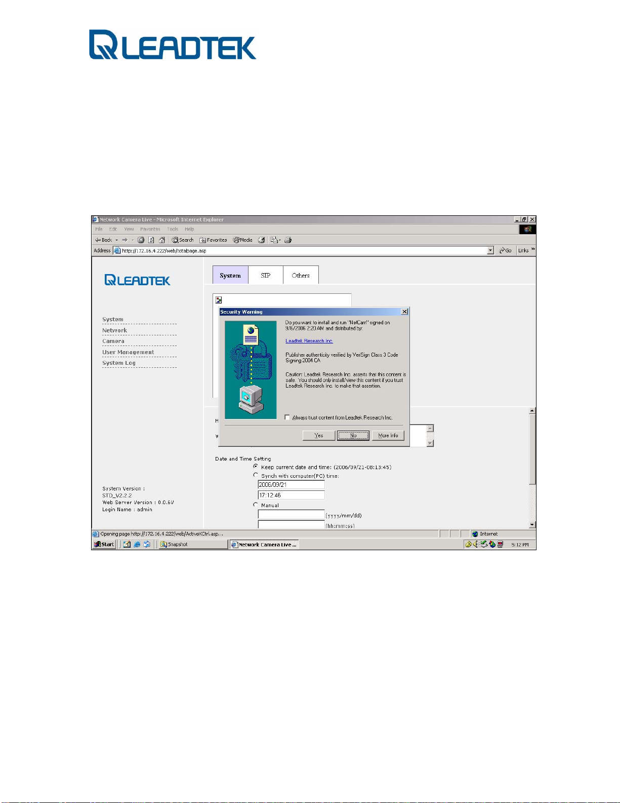
Download ActiveX Control
hen you use IE to connect the web first time, the system will ask you to
download an Active control. To download an ActiveX control will t ake about one
W
minute and the screen below will be displayed. Just press the “Yes” button.to
install...
- Page 28 -
Page 29
T
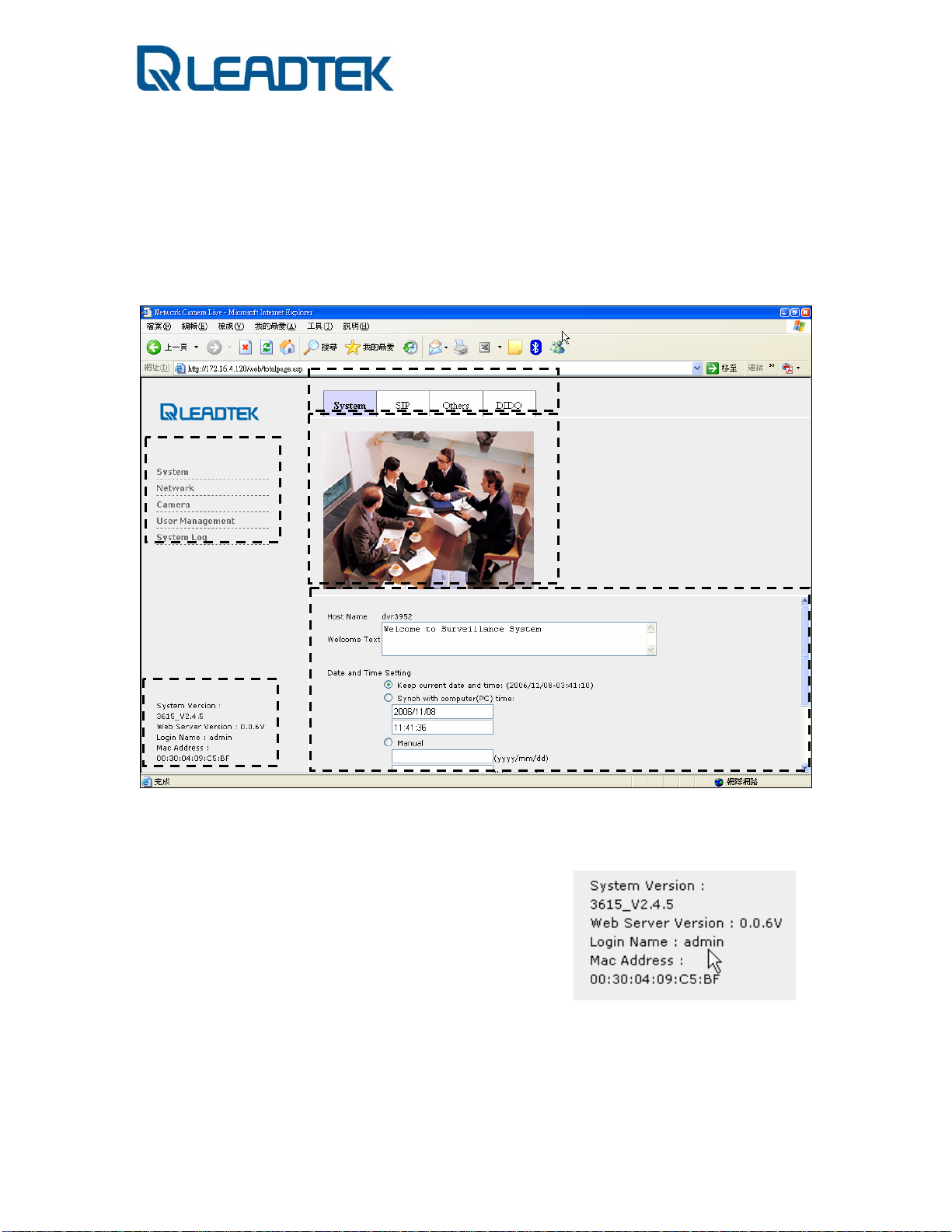
Overlook
hen the screen will appears as below:
A
A
C
D
E
B
A: Menu: There are several items in the left column for you to choose: System,
Network, Camera, User Management, and System Log.
B: Version Information : Will list for users to know the detail information as
following .
9 System Version
9 Web Server Version
9 Login Name
9 MAC address
C: Sub menu: There are several sub- items in
each menu item. It can be switched by mouse click to each menu tab.
D: Live Video: After you installed the ActiveX control, you wil l see t he live
video
E: Setting page : In each item, you can see and modify server configuration.
- Page 29 -
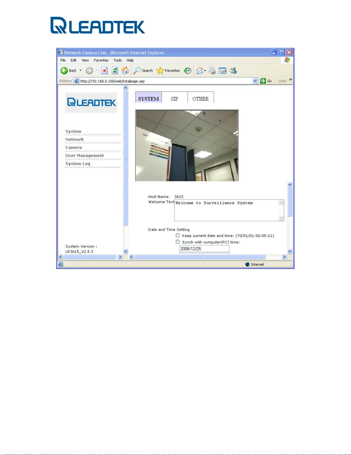
Page 30
System
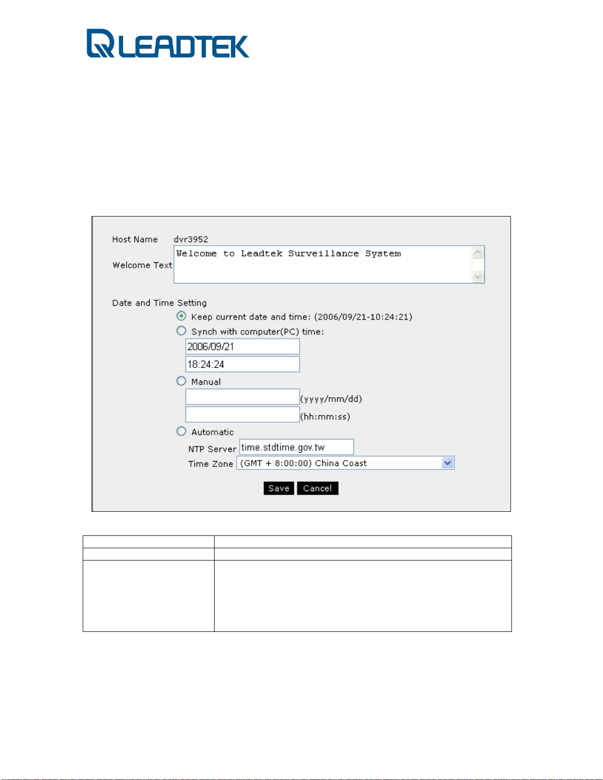
n following screen, you may see 3 different sheets for System, SIP and Other
configuration and can be switched by mouse click to each tabs.
I
System
Host Name Enter host camera name.
Welcome Text Set your own welcome message in the login window.
Date and Time
Setting
1. You can choose to keep current date and time.
2. You can choose to set the time synchronizing with
computer (PC) time.
3. You can choose to set the time manually.
4. You can choose to set the time automatically via SNTP
server (e.g. clock.stdtime.gov.tw) and select Time zone.
- Page 30 -
Page 31

SIP
SIP Phone Name SIP Phone Number
IP Camera SIP Port Surveillance camera’s listen port for SIP invite
SIP Server SIP Server IP (optional)
Server Port SIP Server listen port (optional)
Register Timer SIP Server register timer (second)
Domain Name Domain Name of SIP Server
Proxy Domain Proxy Domain of SIP Server
User Name SIP server registered user name
Password SIP server registered user password
Stun Detect Enable STUN detection or not
Stun Server IP Stun Server IP
Stun Server Port Stun Server Port
Stun Enable HB Enable sending keep alive packet or not
Stun HB Interval The interval of Sending keep alive packet to STUN server
SIP Register Register to SIP server or not
- Page 31 -
Page 32

Others
Upgrade 1. Choose “Kernel” or “Ramdisk” to upgrade
2. Click “Browse…” to choose a valid kernel or ramdisk.
3. Press “Upgrade” to start upgrade.
Download system
Configuration Data
System Reboot Press "Execute" button to perform a soft reboot
Reset Data to Factory
Default
Enable Password The password is saved for viewing of surveillance camera
Input Password Password for live video viewing.
Confirm Password Confirm password for live video viewing.
Click “Download” button to get a current status configuration
Press "Initial" button to enable this function. It will revert its
configuration to factory default setting.
audio/video sources. If the option is enabled, client shall
provide the password and being authenticated by surveillance
camera.
- Page 32 -
Page 33

DIDO
DI Enable Enable Device Input device use
DI Type Select for RISE or FALL type of DI(trigger edge).
IM Notify IP Notify which IP address will be notified after DI triggered .
*SMC will take action on behalf of this configuration .
IM Notify Phone
Number
IM Notify Enable IM Notify or not.
DO Notify Enable if DO will be triggered by DI.
SMTP Send Enable snapshot sending by e-mail(triggered by DI)
FTP Send Enable snapshot sending by FTP (triggered by DI)
DO Type Configuration for DO trigged type(RISE or FALL)
Notify which number will be notified after DI triggered .
*SMC will take action on behalf of this configuration .
*SMC will take action on behalf of this configuration .
- Page 33 -
Page 34

Network Control
n following screen, you may see 3 different sheets for IP, FTP and SMTP
configuration and can be switched by mouse click to each tabs.
I
IP
DHCP DHCP mode for acquiring an IP from DHCP server
Static IP Assign and arrange IP setting on your plan. Including the
IP address / Subnet Mask / Default gateway / Primary
DNS / Secondary DNS settings
PPPoE Especially for ADSL users who can set their account and
password to get online.
☆ Need to RESTART the IPCAM after modifying the Network configurations .
- Page 34 -
Page 35

FTP
Server Name FTP Server IP or Domain Name
Login Name Login account for FTP server
Password Login password for FTP server
Note: This setting is effective when a snapshot sen d ing is triggered by surveillance
camera.
- Page 35 -
Page 36

SMTP
Server Name SMTP Server IP or Domain Name
Login Name SMTP mail account
Password Password for the SMTP mail account
Send From Sender information
Send To Receiver email address
Send To The 2nd Receiver
Send To The 3rd Receiver
Mail Title Subject of the email
Mail Message Mail content. User could write the message inside the
text area.
Note: This setting is effective when a snapshot sen d ing is triggered by surveillance
camera.
- Page 36 -
Page 37

DDNS
DDNS Client Enable Enable DDNS Client Support .
DDNS Alias Alias DNS name
DDNS Username DDNS service account username
DDNS Password DDNS service password
DDNS Uptimer DDNS Uptimer setting
DDNS Fuptimer DDNS Fuptimer setting
DDNS System ID System ID of DDNS, please use DYNDNS_DYNAMIC
Note: For DDNS account subscription, please visit
subscribe the service for your surveillance camera.
http://www.dyndns.org and
- Page 37 -
Page 38

RTP Port
RTP Port range form Allow users to specify the RTP port range to send media
stream from surveillance camera
☆Please consult IT/MIS staff before you make modification of this configuration.
- Page 38 -
Page 39

Camera
Camera
Resolution Adjust the resolution of the image (Restart required)
Bit rate Control the available bandwidth.
Frame Rate Choose the number of maximum frames to be sent by
surveillance in frame per second
Brightness Adjust the brightness of the image.
Contrast Adjust the contrast of the image
Saturation Adjust the color saturation level of the image.
HUE Adjust the hue of the image.
Auto WB
AE Adjust the Auto Exposure of the image.
Color temperature Color temperature
Rotation Image rotation in 180 degree(image flip/ upside down)
Adjust the white balance of the onscreen image.
- Page 39 -
Page 40

Encode Type
Audio Type Configure audio encode type sent by surveillance
camera.
- G.711 a-law
- G.711 mu-law
Video Type Configure video encode type sent by surveillance
camera.
- MPEG4
- H.263
- Page 40 -
Page 41

User Management Control
n following screen, administrators could add/modify/delete extra login accounts to
Manage/View the website contents .
I
New User Press New User button to add users
Edit Edit user’s privilege control
Delete Delete users
Set Set user’s privilege control
Set
There are 3 levels of user privilege control in Leadtek network surveillance camera:
Administrator, Manager, Guest
Each group users are authorized with different web page management permissions.
- Page 41 -
Page 42

System Log
The system log book keeps system operating history in a cyclic way. The newest log
record will over write the oldest log record.
- Page 42 -
Page 43

Restore to factory default
If the system is up and running, you can push factory default button through pinhole
of surveillance camera (marked as Restore default, the Reset is used to perform a
warm system reboot). The firmware will recover the sett ing to factory default.The
following configuration is the firmware factory default setting:
Default IP Setting
IP mode: Fixed IP
IP address: 192.168.0.100
Subnet mask: 255.255.255.0
Webs Default User Account
Username: admin
Password: admin
- Page 43 -
Page 44

How to use SMC ?
How to use SMC ?
Install Surveillance Management
Center
hile inserting the Video Surveillance Software Pack CD into the CD-ROM ,
the program will self running with the following win dow .
W
In above screen, SMC stands for Surveillance Management Center , specially
designed for the Leadtek Surveillance products .You may take advantage of the
software to control and manage Leadtek Surveillance products .
Press Next for continuing the install process .
- Page 44 -
Page 45

Please read the EULA carefully. Leadtek SMC is legally used for the Leadtek
Surveillance Products and well-protected by the Copyright law.
Press Next for continuing the installation process.
- Page 45 -
Page 46

Click the button marked by RED color and choose an installat ion folder or click Next
to stay the default installation folder to continue the installation process.
- Page 46 -
Page 47

Click the Install to start the installation of SMC.
- Page 47 -
Page 48

You will see the installation progress from the green progress bar. While finished,
please press Finish when installation is complete.
Launching the SMC / Scheduler
ou will see the 3 item added into the list of program files . SMC , Scheduler and
the Uninstaller .
Y
9 SMC:Surveillance Management Center main program
9 Schedu ler : SMC scheduler controlling service
9 Uninstaller : shortcut to uninstall SMC
- Page 48 -
Page 49

Click the SMC to launch the SMC .
☆There will be a shortcut added to your deskto p . Try to find an icon listed there to q uick launching
the SMC .
Finding Surveillance Cameras
hen first launching the SMC , SMC will launch the ADD CAMERA function for
users to find surveillance devices in the same LAN segment.
W
There are five buttons below the grids and each one has its own definition for ADD
camera .
9 SCAN
subnet .
9 MODIFY
9 ADD
9 APPLY
selected cameras .
9 BACK
: Used for searching the Surveillance Cameras under the same
: Change the selected cameras properties .
: Add a new camera with your own selection / setting.
: Apply the configuration now and start to monitor from the
: Back to the monitor of surveillance .
- Page 49 -
Page 50

SCAN
The SCAN function is designed for the camera search when you install multiple
cameras under the same LAN . Leadtek surveillance cameras are detectable by
Leadtek Surveillance Management Center.
- Page 50 -
Page 51

The scanned cameras will be listed in the Scan grid and with the hostname and IP
displayed. Hostname stands for device identifier (a nickname) or SIP telephone
number and the IP is current IP address of the surveillance camera ☆
Users may double-click the Scan camera button or press the right arrow sign to add
the camera into the managed group on the right panel.
☆ We assume that the PC software is installed to a LAN PC , so the SMC can do the SCAN . If under the WAN , the
SCAN function may not function well across router .
.
☆ The scan function can search all the surveillance camera in the same subnet. Those cameras with different subnet
setting or not being configured as the same subnet of SMC will not be searched by our SMC. You will need another
scan utility to scan those cameras in local area network (with different network setting but installed within same
router)
☆ You can connect to those surveillance camera found by SMC scan. The SMC can not connect to those cameras
with improper network setting (not found by SMC scan). Check your surveillance camera network setting if you fail to
scan the camera.
- Page 51 -
Page 52

MODIFY
SMC provides 2 modes to make live connections to surveillance camera. One is P2P
(peer-to-peer) and the other is Using SIP Server. The scanned camera list is all for
P2P mode. Each surveillance camera comes with a default Hostname which is just a
name keeper for user’s reference in P2P mode. Users can offer nickname in the field
of IPcam ID to keep track of his camera. The nickname will be displayed on screen
text overlay of SMC. If the live connection is made via P2P mode (SIP server not
involved), you can also use the Hostname as the second nickname to become more
easily to remember. Click the selected camera and click the MODIFY button to
modify the setting.
- Page 52 -
Page 53

If the live connection is made via SIP proxy server, you shall select Use SIP Server
in Connection Mode field. Note that you shall also offer the correct SIP proxy
server IP in the IP Address field so that SMC will refer to that designated SIP server
for specified surveillance camera(via phone number of Hostname). The Password
filed is mandatory and shall be learned and given in advan ce so that live video can
be displayed in SMC. Otherwise, you may just receive a short video clip to ask for
password authentication.
Press ADD to complete the modification.
- Page 53 -
Page 54

APPLY
Press APPLY to start the monitoring all the selected surveillance cameras on the
right panel.
- Page 54 -
Page 55

BACK
Under ADD CAMERA mode , press BACK anytime to go back the monitor screen
which displays the camera selected previously .
- Page 55 -
Page 56

ADD
You won’t often use the ADD function to add the same LAN cameras unless you have
the Use SIP Server connection mode or you have an surveillance camera installed
with a permanent public IP address.
9 IPcam ID : you can input a nickname of his surveillance camera
9 IP Address : the surveillance camera’s IP address(Peer to peer), a all
zero shall be given for SIP proxy mode(Use SIP Server)
9 Hostname : surveillance camera’s SIP phone number(Use SIP Server)
or nickname (P2P mode)
9 Connection Mode : Choose the connection type between :
Peer to Peer
Use SIP Server
9 Password : If remote view permission password is enabled, you shall
provide the viewing password here when making the connection in
advance. Otherwise, a privacy screen will be displayed. The viewing
password is authenticated each time by the surveillance camera when a
remote client requests remote camera viewing .
After finishing filling up mandatory fields, press ADD to complete the camera adding
process.
- Page 56 -
Page 57

☆If surveillance camera viewing password is enabled and Password is not
provided before ADD, the input password will pop up and authentication is
required to view live video.
The Password can be provided after APPLY. You can input the password of
designated surveillance camera by selecting Input password screen ( an green
- Page 57 -
Page 58

outline around the video block ), input the password on CameraÆGeneral
SettingÆPassword (on left hand side panel) and click OK to authenticate user
password.
- Page 58 -
Page 59

Basic Operation
ith a simple command bar above the SMC , you may control with the
surveillance cameras easily., i.e. Record/Snapshot/Change Layout/Full Screen
W
etc. Here is the introduction of the command bar .
Recording
The Record button is set for manually recording . While you want to record some
video clips for special use , you can press the button directly . The monitor will
display with a RED mark of REC to show the recording has been started .
Press again to stop the manual recording ☆.
☆ The recorded files will be stored at PC software side , i.e. if users install the SMC in a PC/Laptop , the PC/Laptop
will store the video clips until the disk space has been run out of .
- Page 59 -
Page 60

Snapshot
The Snapshot button is set for manually image capture . While you want to take a
monitor shot from the displaying view , press the button directly then the snapshot
has been taken and stored into the local drive.
Send Voice
You can use Leadtek surveillance cameras to start a 2-way audio conversation. While
you want to have a 2-way communication with 1 selected camera , click the screen
to set focus to it (green circled ) and press the SendVoice button to start the talk
You can start a 2-way audio with one specific surveillance camera. If the surveillance
camera 2-way audio talk is busy, the second audio talk invit ation will fail and a
warning message "Audio line is busy , try later" will display to indicate audio line
busy condition.
☆.
☆PC/Laptop should got microphone device to enable the SendVoice function ; also the
surveillance camera should have the speaker installed before starting the talk .
- Page 60 -
.
Page 61

Change Layout
Leadtek Surveillance Cameras can be installed to many places . For the monitoring
convenience , SMC can support up to 9 cameras' view at the same time
the button to toggle the layout view from 1/4/9 and back to the single view .
☆ . Press
☆ It depends on the hardware performance . CPU/RAM should be considered before viewing the cameras .
Full Screen
Press the button to view the video in full screen.
Add Camera
- Page 61 -
Page 62

Press the button will bring you back to the first window just like you lau nch the SM C .
.
File Viewer
The FileViewer function is for browsing the Recorded files and Snapshot pictures .
Press the button and you can have the following window pop-up.
- Page 62 -
Page 63

There's a filter will help you to find the files qu ickly , which can filter the files with
TYPE(Snapshot/Recording/Motion Detect/All) and Time Period .
- Page 63 -
Page 64

After the filter criteria has been decided , press Search to get the result . No matter
what type you filtered, press View to have the file displayed at the right area or
deleted with pressing the Delete.
- Page 64 -
Page 65

Advanced Operation
or more detailed instruction of SMC , we will take 3 parts to show you how to
do .
F
9 Camera
information , i.e. Device Info , Image control and Ethernet
configuration
9 General Setting
and Recording path and also the record priority .
9 Advanced Setting
here.
9 PTZ
: For knowing/controlling the Surveillance camera basic
: Surveillance Camera Caption , Audio/MIC control
: You can set the Motion Detect / DIDO and STUN
: For the PTZ capable camera features
Camera
You can click the monitor screen and set focus to it , then click to the left side
button for Camera setting . We will have the following picture to know the basic
information of a surveillance camera .
No matter what setting has been modified , press Apply to have the
configuration enabled .
a. Device & Image
Page 66

Resolution Adjust the resolution of the image (Restart required)
Bit rate Control the available bandwidth.
Frame Rate Choose the number of frames to be displayed in a
second.
Brightness Adjust the brightness of the image.
Contrast Adjust the contrast of the image
Saturation Adjust the color saturation level of the image.
HUE Adjust the HUE of the image.
Auto White Balance
Adjust the white balance of the onscreen image for
ON/OFF.
Auto Exposure Adjust the Auto Exposure of the image for ON/OFF.
Color temperature Color temperature
- 2850K
- 4300K
- 6500K
Frequency 50MHz or 60MHz for AC power frequency.
Rotate Camera Image rotation if needed while IPCAM is on desktop or
attached to ceiling.
b. Network
- Page 66 -
Page 67

DHCP DHCP mode for requiring an IP from DHCP server
Static IP You can configure IP setting of surveillance camera.
Including the IP address / Subnet Mask / Default
gateway / Primary DNS / Secondary DNS settings
PPPoE Especially for ADSL users who can set their account and
password to get online.
General Setting
You can enable/disable the screen caption to a surveillance camera and also the
Audio/MIC's on/off .
As to the Recording , you may define the recording path to store the manual
recording and the schedule recording . Due to the video clip file size is often huge,
please check Free Drive Space of you local disk storage☆.
☆ If there's not enough Free Drive Space , please change the Recording Path to see if there's enough space at other
system disk .
- Page 67 -
Page 68

For the Record Priority , you can define which kind of recording will be prior than
any others.
9 Manual
9 Event
9 Scheduler
: Recording is enable by Record the top of the SMC
: Record is triggered by the Motion Detection
: Recording is enabled by Scheduler.
Advance Setting
You may have Motion Detect or DIDO setting for their security . Before the
Motion Detect secure area setting, some parameters need to be set and predefined before starting the Motion Detect/DIDO.
c. Motion Detect
- Page 68 -
Page 69

9 Sensitivity
(%):This parameter determines the sensitivity of
embedded motion detector algorithm. The higher the value, the more
sensible to the motion object change.
9 Object size
(%) : This parameter determines the pixel change
percentage of motion interest area. If more pixels(vs configured value)
are justified and declared as changed by embedded motion detector
algorithm, motion is reported by the device.
9 Frame Interval
: the number of required video frames in a row to
confirm the motion condition. The smaller the value, the higher
motion probability.
9 Alarm Duration
: This parameter specifies period of interval to start
next motion detection. If one motion event is confirmed and declared,
it is required to wait for the time specified by this parameter so that
the next motion event can be start to detect.
9 Area of Detection
: Define the detection area ; 3 areas , each one
needs to be defined separately ☆ .
9 SMTP Setting
: Configure the SMTP for sending out the captured
image from surveillance camera☆.
9 FTP setting
:Configure the FTP for transferring the captured images
from surveillance camera ☆.
9 NetCam Action
9 Client Action
: Invoke DO/send email/send ftp
: Snapshot / Recording Setting
- Page 69 -
Page 70

9 Number of Snapshot : While enable the Client Action with
Snapshot , set the Number of Snapshot to define the alarm pictures
amount .
9 Event Rec. duration
: After the time of duration set , the alarm will
be cleared and wait for another trigger point .
☆ How to define an area of Detection ?
1. Press AREA1 and see the black window jump out
2. Click the black screen , drag and drop with an area in red line to mark the
area of motion detection.
- Page 70 -
Page 71

3. Enable the area and press Save .
☆ How to define SMTP to send the image via email ?
- Page 71 -
.
Page 72

1. Press SMTP button and have the SMTP setting window.
2. Fill in with proper information. Here we only provide an example for input
texts.
☆ How to define FTP to send the images up to a FTP Server?
1. Press FTP button and have the FTP setting window.
2. Fill in with proper information . Here we only provide an example for input
texts.
d. DIDO
- Page 72 -
Page 73

9 DI / Enable: ON/OFF for DI
9 DI / Type : Low / Raising for trigger mode .
9 DI / IPCAM Action : Define what action will be done if DI triggered .
9 DO / Type : Low / Raising for action mode .
e. Other
- Page 73 -
Page 74

9 Using SIP Server : ON/OFF for using the SIP Server
9 SIP Phone : SIP Phone number
9 SIP Server : SIP Server IP Address
9 SIP Port : SIP Server port used ( often 5060 )
9 STUN Detect : ON/OFF for using the STUN Server
9 STUN Server : STUN Server IP Address
9 STUN Port : STUN Server port used ( often 3478 )
9 Select PC Network Interface : If multi network cards , users need
to define which one for the connection .
9 Version : SMC version
- Page 74 -
Page 75

PTZ
For advanced model with the surveillance devices, Leadtek offer models for
supporting the Pan/Tilt/Zoom features . If you also buy the PTZ series camera,
then after SCAN from the Surveillance Management Center ( SMC ) , the PTZ
camera can be also ADD into the camera list and to be monitored at the same
time .
Standard Operation
Leadtek PTZ surveillance camera offers a standard operation panel and advanced
configuration panel for users . And for standard operation, there are 4 areas for
different control which are:
☆ If a non-PTZ IPCAM was selected , the PTZ Panel won't be activated .
a. Navigation
- Page 75 -
Page 76
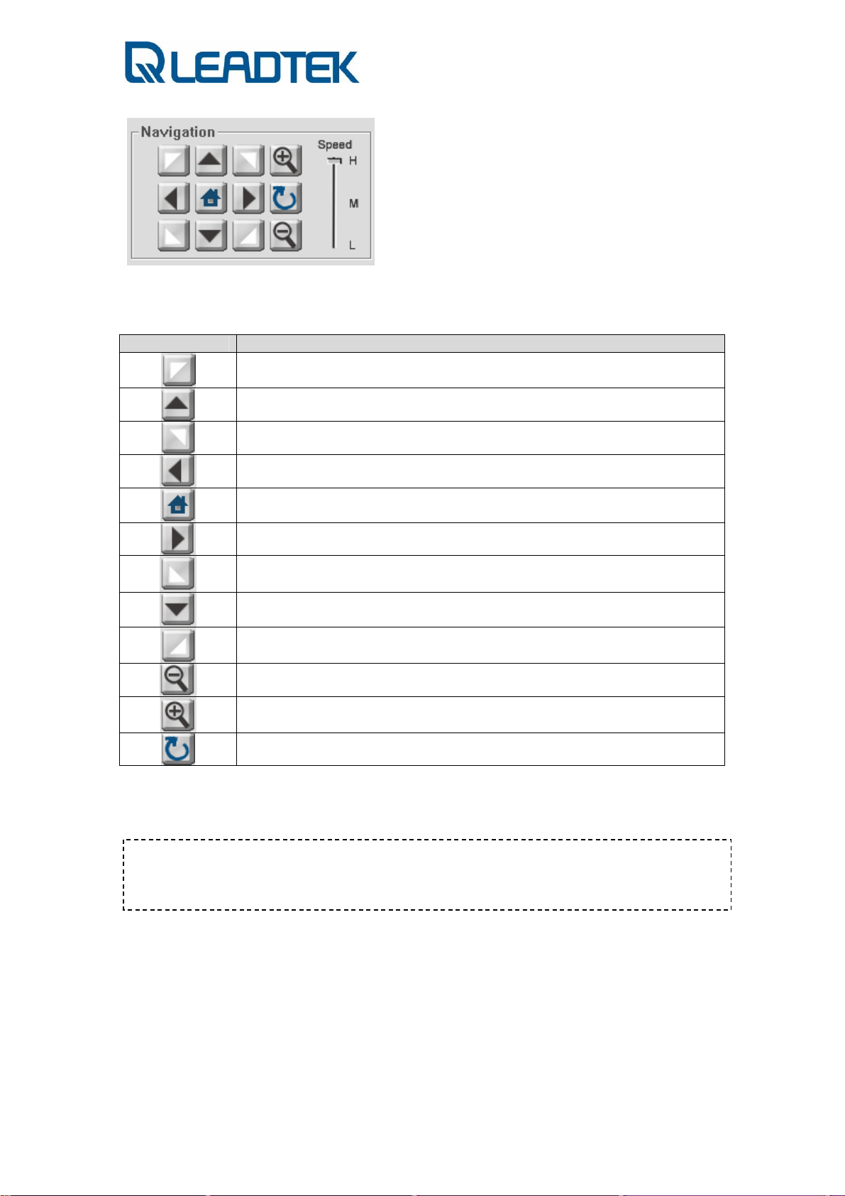
While the PTZ models being selected, the Navigation control panel can help users
to do the manually control with the Pan, Tilt and Zoom features.
Symbol Description
Control the direction of UP-LEFT
Control the direction of UP
Control the direction of UP-RIGHT
Control the direction of LEFT
Control the RESET TO DEFAULT POSITION (HOME position)
*Both direction and the focus.
Control the direction of RIGHT
Control the direction of DOWN-LEFT
Control the direction of DOWN
Control the direction of RIGHT-DOWN
Control the ZOOM OUT
Control the ZOOM IN
Reset the Zoom to the default.
☆ Each button can be pressed only once in and remain state of disable for 1 sec . Due to the transmission quality
is limited by the network bandwidth , so users can do the PTZ control once a second . If users want to move faster ,
please adjust the SPEED control to the HIGH .
- Page 76 -
Page 77

b. Auto Pan
PTZ camera is able to do the automatically pan with the lowest speed . This
feature is designed for users can do the surveillance and move gent ly via the
horizontal, visible angle of the PTZ camera. To start the Auto pan, press the
button .
While the Auto Pan has been activated, the button state will switch ed to the
pressed mode and a STOP button (
) will be enabled. While the Auto Pan
has been started, please press the STOP to terminate the control .
c. Preset
Preset are the position sets which you may pre-define the spots for the regular
surveillance. Each preset can define its viewing angle and focus, a Preset Name
is also included.
If you already define a Preset Name, a tooltip will pop-up while you roll the
mouse over the Preset buttons, just like the following picture.
d. Cruise
- Page 77 -
Page 78

Cruise is the set of Presets. Each cruise can contain 16 presets in it . If you did
not define the cruise at the beginning ,then the cruise button cannot be press just
like the above figure .
* Cruise has been defined, the cruise button will be enable.
* Cruise has been activated, then the STOP button will be enabled for you
to stop.
PTZ Configuration
In the main panel of PTZ control, SMC allows you to do the manually control from
the functions listed within the panel , such as Navigation , Auto Pan , Preset
navigation and cruise surveillance . For advanced configuration for the Presets
and Cruises , press the PTZ Configuration button .
- Page 78 -
Page 79

A B
C
A:Preset Navigation Area
- You may have a clearly view for what angle of the surveillance camera will be
seen from the preset .
- If you are not satisfied with the originally setting , you could adjust the view
angle and also the focus as wish .
B:Preset Define Area
- There are 16 presets for you to do the presets.
- Press the # of the preset and start the Preset Navigation adjustment
( view angle and the focus adjust ) , the Preset Name can be also added in
at this moment.
- To SAVE, please press the SAVE button below or click another Preset to
define next.
- Press the OK to confirm the modification, or CANCEL to ignore that.
- Page 79 -
Page 80

(1)
(2)
C:Cruise Define Area
The way to define the cruise will count on a process which start with the cruise
set ( A,B,C,D and E ) .
[STEP 1 ]
If now we are trying to configure the Cruise A and after configuration, activate it
is a must. Press A button that just is located in the Cruise panel.
[STEP 2]
After pop-up with the Add Preset window, try to choose which cruise route that
you would like define.
The Duration here defines the pause time between 2 presets for users to
watch/monitor the Preset more clearly.
☆ If not required, the 16 presets don't need to be defined completely . 2 Presets can be a Cruise if users activate
the Cruise right beside the row by checking it .
- Page 80 -
Page 81

[STEP 3]
Here we define the Preset 2 and 6 for the Cruise A and the Duration time is 6
seconds. Press OK to finish the Press adding.
Now you may see the Cruise A has been filled with some information we've just
defined few minutes ago. But it is not enable yet.
Be noticed with what is going to do next.
We need to Enable what we've done for the Cruise set, i.e. if users did not
activate the cruise, the standard operation panel won't have a activated button
for users to execute the cruise surveillance.
* The message above show you to confirm the modification of activating Cruise
A . Press OK to save or CANEL to ignore the change.
What will be changed in the front panel after press CLOSE? The picture below can
tell you what's going on after th is.
- Page 81 -
Page 82

Using Camera with a Router
Using Camera with a Router
If users connect their own surveillance camera and / or PC to a router to access
Internet, the router automatically assign IP address to each device. Those IP
addresses assigned by the router are under private IP address range (depicted in
the following figure).
Private IP address range:
z 10.0.0.0 - 10.255.255.255 : private IP address range
z 172.16.0.0 - 172.31.255.255 : private IP address range
z 192.168.0.0 - 192.168.255.255 : private IP address range
- Page 82 -
Page 83

z 169.254.0.0 - 169.254.255.255 ( DHCP link failure address setting)
z 0.0.0.0 : invalid IP address
Follow up the flow chart and justify your Internet subscription from ISP. Three
networking modes are deduced and proper IP address assignment should be
given accordingly.
- Page 83 -
Page 84

Install
Surveillance
Camera
Internet Access
Subscription
Yes
IP address
assigned by
Router(DHCP)
Yes
Inside NAT Router
Turn on SIP & STUN
option(private IP address)
No
No
Manually Configure
Surveillance Camera with
Fixed IP(arranged by
users)
PPPoE / Fixed IP
Direct Internet
Connection
Assign Surveillance
Camera with Fixed IP /
PPPoE(public IP address)
A. DHCP(private IP address):
Configure your surveillance camera with DHCP mode from web page Network Æ
IP
Save and reboot your surveillance camera to make the settin g effective.
Note: If you want to access your LAN(behind NAT router) from Internet, make
sure your STUN and SIP option are both turned on(both Windows client and
surveillance camera) in order pass media packets through routers.
Procedure to Turn on SIP and STUN Option:
- Page 84 -
Page 85

I. SIP and STUN Option on SMC:
SIP Option:
If you are making an SIP proxy connection to surveillance camera, make sure you
have already configured SIP proxy setting of SMC itself. The SIP proxy setting can
be modified from Advance Setting Æ Other . Make sure Using SIP Server
option is ON. You need to restart SMC to make the new SIP proxy setting to be
effective.
STUN Option:
From Advance Setting Æ Other, make sure STUN Detect is ON.
Note : For SIP Phone / SIP Server / SIP port / STUN Server / STUN Port
parameter settings, you can contact VoIP service provider and subscribe a
account to use. Please contact
ipcamfae@leadtek.com.tw for further detail.
II. SIP and STUN Option in Surveillance Camera:
SIP Option:
Log on to surveillance web page. From webpage System Æ SIP, ensure Sip
Register option is ON.
STUN Option:
From webpage System Æ SIP, ensure Stun Detect option is ON.
- Page 85 -
Page 86

Note : For SIP Phone / SIP Server / SIP port / STUN Server / STUN Port / Stun
Enable HB parameter settings, you can contact VoIP service provider and
subscribe a account to use. Please contact
detail. The following snapshot is just an example setting for demo
purpose only. You shall not input the setting to their own surveillance
camera.
ipcamfae@leadtek.com.tw for further
B. Static IP or PPPoE(public IP address):
Fill the network PPPoE account/password provided by your ISP from web page
Network Æ IP. Save and reboot your surveillance camera. Surveillance camera
will boot up and dial-up to Internet with PPPoE account(a public IP address).
- Page 86 -
Page 87

Note : The example snapshot is just an example. You shall input the setting of
your PPPoE account given by your ISP.
C. Without Internet Access(arranged by users):
If you have no Internet access link, they can manually configure their networking
device and make sure each device IP address is unique and is of a same subnet.
The following network scenario is a quick example.
PC Setting:
IP address : 192.168.0.1
Subnet mask : 255.255.255.0
Surveillance Camera Setting:
IP address : 192.168.0.100
Subnet mask : 255.255.255.0
Available IP address range : 192.168.0.2 ~ 192.168.0.254 (exclude
192.168.0.100)
From web page Network Æ IP
- Page 87 -
Page 88

Appendix
Installing Scan Utility
The following procedures guide you through the steps of scan utility installation
and operation:
Step 1 : Visit WinPcap and download WinPcap version 3.1 from the website:
Step 2 : Install WinPcap version 3.1(Installer for Windows / WinPcap_3_1.exe).
http://www.winpcap.org/
i) Double click WinPcap_3_1.exe icon.
ii) Click Next to continue.
- Page 88 -
Page 89

iii) Click I Agree to continue.
iv) Click Finish to complete installation.
- Page 89 -
Page 90

Step 3 : Launch Scan Utility and Assign new IP address to surveillance camera
i) Double click the scan utility iiap.exe
ii) Click Scan button to send out scan packet to the LAN.
- Page 90 -
Page 91

iii) The found devices will be displayed on lower panel of utility
program. The Status field shows you whether the device is ON
LINE(configured in same subnet) or IDLE(not configured properly
in the same subnet). If you want to modify the network setting of
specific device, click the item to select the interested device. T he
detail network setting of the device will be displayed on upper part
fields. Modify the necessary fields and click Assign to change
designated device network setting. If network setting assignment is
successful, a confirmation message box will pop up to indicate this.
Upon a successful Assign operation, assigned surveillance device
will accept your designated network setting and reboot itself to be
effective right away. The default IP network mode w ill be changed
to Fixed IP mode after reboot(manually assigned by user’s).
- Page 91 -
Page 92

☆The standalone scan utility mention ed here can look up all the cameras in the sam e subnet(within
same router boundary). The SMC scan function just find those camera located in the same subnet with
SMC. If surveillance camera’s IP address setting is not properly configur ed with SMC. The Status field
will be IDLE and the connection to the surveillance ca mera via SMC may fail due to improper network
setting in surveillance camera. Check your surveillance network setting and justify whether the
setting is of a same subnet of SMC.
Firmware Upgrade
Surveillance camera firmware can be upgraded via Microsoft Internet Explorer.
Prepare the firmware file and follow the procedure as the following:
1) Login on to web, and click System Æ Others page.
2) Ensure Ramdisk radio button is selected. Click Browse button to choose the
firmware file and then click Upgrade button to kick start firmware upgrade
procedure.
- Page 92 -
Page 93

3) A message box pops up and a down counter shows the remaining time left of
the whole upgrade procedure. The surveillance camera will reboot itself
automatically when the upgrade procedure is done.
4) The surveillance camera rolls back its configuration to factory default when this
procedure is done.
Note: Depends on firmware version to be upgraded, surveillance camera may
reboot itself with factory default or maintain its original setting.
Note: Check the NSC3615 LED to ensure the surveillance camera reboot itself
properly.
- Page 93 -
Page 94

Frequently Asked Questions
Network Configuration
Category : IPCAM / Installation / General
Question:
How can I determine my network setting / configuration ?
Answer:
You shall verify what kind of your user PC network access point are
you in(public/private IP address).
The following figure is an example. Justify your network access
point(User PC A /B/C)
NSC3615
( Global IP : 211.72.242.91 )
( Private IP : 192.168.0.1 )
User PC B
1 NAT :
( IP: 192.168.0.3 )
NAT Router
co
r
p
o
r
a
( IP: 172.16.0.62 )
t
e
/
h
o
me
User PC C
2 NAT:
L
e
a
d
Internet
L
A
N
User PC A(public)
( IP: 62.128.30.57 )
t
e
k
L
i
v
e
D
e
m
o
( IP: 220.128.22.97 )
( IP: 59.120.205.60 )
NSC3615
If you do not know your IP address of PC / notebook, enter the
command as the snapshot to find out:
- Page 94 -
Page 95

If the “IP Address” field displayed is included in the following range,
your PC is located in a private LAN
Private IP address range:
z 10.0.0.0 - 10.255.255.255 : private IP address range
z 172.16.0.0 - 172.31.255.255 : private IP address range
z 192.168.0.0 - 192.168.255.255 : private IP address range
z 169.254.0.0 - 169.254.255.255 ( DHCP link failure address
setting)
z 0.0.0.0 : invalid IP address
If you have direct Internet access(e.g. IP address 61.128.30.57)
without an firewall or NAT router installed, you possibly can directly
link to Leadtek IPCAM live demo site(IP address : 220.128.220.97,
etc on the figure above) and get a real-time live view.
From dos shell command, you can input “tracert” command and see
how your packet goes to Internet. Take our IPCAM Internet live
demo as an example, you can find out how many router hop are
there and thus learn your network configuration.
3 Router to Internet Case
Local PC Æ 192.168.129.254(Router 1/private IP address)
Æ172.16.5.254(Router 2/private IP address)
Æ172.16.1.253(Router 3/private IP address)Æ …
- Page 95 -
Page 96

Direct Internet Connection Case
Local PC Æ 211.72.242.254(Router 1/public IP address)
Æ168.95.82.202(Router 2/public address) Æ …
- Page 96 -
Page 97

Surveillance Management
Center
- Page 97 -
Page 98

Version Information
Category : SMC / Installation / General
Question:
How can I find out the version information of Windows client
(Surveillance Management Center, a.k.a. SMC) ?
Answer:
Please refer to SMC “Advance Setting” Æ “ Other”
- Page 98 -
Page 99

- Page 99 -
Page 100

SIP Configuration
Category : SMC / Configuration / General
Question:
How to verify SIP connection mode for A/V transmission in
NSC3615(Peer-to-peer or SIP proxy) ? How do I configure SIP
connection mode on SMC?
Answer:
SMC supports 2 mode of SIP connection, i.e. peer-to-peer or via SIP
proxy. A SIP phone number shall be pre-configured before make the
SIP call to IPCam server. For a peer-to-peer mode, the IP address of
target IPCam shall be designated before launching IPCam connection.
If you are making an SIP proxy connection to IPCam server, make
sure you have already configured SIP proxy setting of SMC itself. The
SIP proxy setting can be modified from “Advance Setting” Æ”Other”
Make sure “Using SIP Server” option is “ON”.
You need to restart SMC to make the new SIP proxy setting to be
effective.
- Page 100 -
 Loading...