

Page 1

LR9552
GPS Module
i
Page 2

1. INTRODUCTION..................................................................................................................1
1.1. FEATURES.......................................................................................................... 1
HARDWARE AND SOFTWARE ........................................................................................... 1
PERFORMANCE .............................................................................................................. 1
INTERFACE .................................................................................................................... 1
2. MODULE ARCHITECTURE ..............................................................................................2
2.1. DIMENSIONS ....................................................................................................... 3
2.2. SOFTWARE FEATURES ........................................................................................ 3
2.3. ENVIRONMENTAL SPECIFICATION ......................................................................... 4
2.4. REFERENCE DESIGN............................................................................................ 4
2.5. REGULATIONS COMPLIANCE................................................................................. 5
3. PERFORMANCE CHARACTERISTICS...........................................................................7
3.1. POSITION AND VELOCITY ACCURACY..................................................................... 7
3.2. DYNAMIC CONSTRAINS ........................................................................................ 7
3.3. ACQUISITION TIME 1............................................................................................. 7
3.4. TIMING 1PPS OUTPUT......................................................................................... 8
3.5. SENSITIVITY........................................................................................................ 8
4. HARDWARE INTERFACE POWER SUPPLY.................................................................9
4.1. SPECIFICATIONS.................................................................................................. 9
I. Pin Positions ....................................................................................................................9
II. Pin Assignment...............................................................................................................10
5. SOFTWARE INTERFACE.................................................................................................11
6. MECHANICAL DRAWING AND FOOTPRINT............................................................12
6.1. OUTLINE DRAWING ........................................................................................... 12
7. PACKAGE............................................................................................................................13
7.1. PACKAGE SPECIFICATIONS ................................................................................ 13
8. ROHS COMPLIANT INFORMATION............................................................................14
8.1. ROHS SOLDERING PROFILE ............................................................................... 14
Reflow Profile.........................................................................................................................14
GLOSSARY..................................................................................................................................15
ii
Page 3

LR9552 Manual V04
1. Introduction
The Leadtek GPS 9952 module (LR9552) is a high sensitivity and very compact smart antenna module,
with built in GPS receiver circuit. This 20-channel global positioning system (GPS) receiver is
designed for a wide range of OEM applications and is based on the fast and deep GPS signal search
capabilities of SiRFStarIII™ architecture. Leadtek GPS 9552 is designed to allow quick and easy
integration into GPS-related applications such as:
λ PDA, Pocket PC, and other computing devices
λ Car and Marine Navigation
λ Fleet Management /Asset Tracking
λ AVL and Location-Based Services
λ Hand-Held Device for Personal Positioning and Navigation
1.1. Features
Hardware and Software
λ Based on the high performance features of the SiRF GSC3f/LP single chip
λ Compact module size for easy integration: 25 x 25 x 8.9 mm (with 4 mm patch antenna)
25 x 25 x 6.9 mm (with 2 mm patch antenna) [option]
λ Fully automatic assembly: reflow solder assembly ready
λ Hardware compatible with SiRF GSW3.2 serial software
Performance
λ Cold/Warm/Hot Start Time: 42/38/1 sec.
λ Reacquisition Time: 0.1 second.
λ RF Metal Shield for best performance in noisy environments.
Interface
λ RS232 or TTL (option) level serial port for GPS communications interface
λ Protocol: NMEA-0183/SiRF Binary (default NMEA).
λ Baud Rate: 4800 ~ 57600 baud (default 4800).
© 2006 Leadtek Research Inc. All rights reserved. Page 1/18
Preliminary Confidential - Information is subject to change without prior notice.
Page 4
LR9552 Manual V04
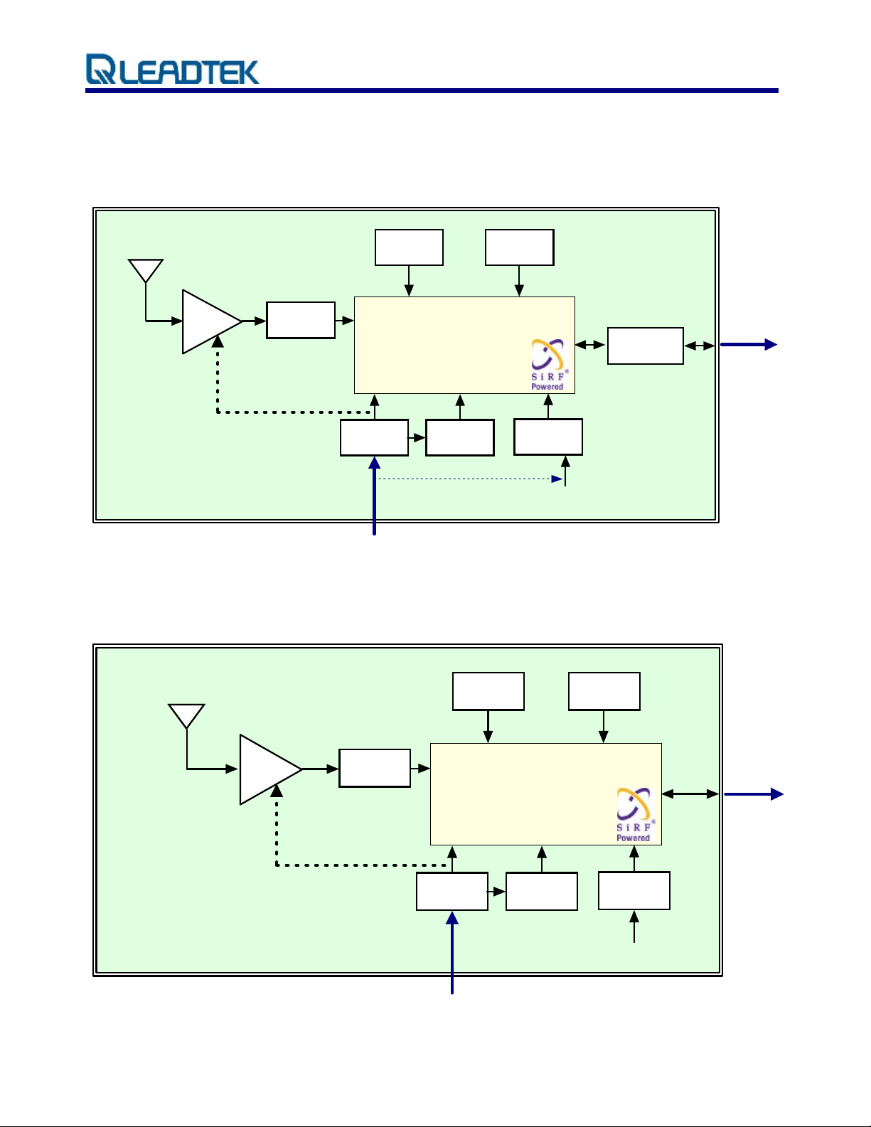
2. Module architecture
LR9552
9552LP ( RS232 ) Block Diagram
25mm Patch Antenna
16.369MHz
TCXO
bandpass
LNA
filter
SiRF GSC3f / LP
2.85 VDC
regulator
voltage
detector
32.768KHz
Crystal
1.50 VDC
regulator
RS232
Transceiver
NMEA
output
backup battery
5.0VDC power in
9552 ( TTL ) Block Diagram
25mm Patch Antenna
16.369MHz
TCXO
bandpass
LNA
filter
32.768KHz
Crystal
serial
IO
NMEA
output
SiRF GSC3f
2.85 VDC
regulator
voltage
detector
5.0VDC power in
© 2006 Leadtek Research Inc. All rights reserved. Page 2/18
Preliminary Confidential - Information is subject to change without prior notice.
1.50 VDC
regulator
backup battery
Page 5

LR9552 Manual V04
2.1. Dimensions
The Physical dimensions of the Leadtek 9552 GPS Module are as follow:
Items Description
Length 25.0 ± 0.3 mm Width 25.0 ± 0.3 mm
Height
8.90 ± 0.3 mm
6.90 ± 0.3 mm
Weight
13.0g (w/ 4mm patch antenna)
8.0g (w/ 2mm patch antenna)
2.2. Software Features
The Leadtek 9552 module includes GSW3.2., high sensitivity software solution. For
SiRFStarIII/LP receivers, the default configuration is as follows:
Item Description
Core of firmware 3.2 SiRF GSW
Baud rate 4800, 9600, 19200, 38400 or 57600 bps (default 4800)
Code type NMEA-0183 ASCII
Datum WGS-84
Protocol message GSA(5sec), GSV(5sec), RMC(1sec),VTG(1sec)GGA(1sec),
Output frequency 1 Hz
© 2006 Leadtek Research Inc. All rights reserved. Page 3/18
Preliminary Confidential - Information is subject to change without prior notice.
Page 6
LR9552 Manual V04
2.3. Environmental Specification
Item Description
Operating temperature rang (note) -30 deg. C to +60 deg. C Storage temperature range -30 deg. C to +65 deg. C Humidity up to 95% non-condensing or a wet bulb temperature of +35 deg. C Altitude 18,000 meters (60,000 feet) max. Velocity 515 meters/second (1000 knots) max. Jerk 20 meters/second3, max.
Acceleration 4g, max.
Note: The module can be operated between -30℃~+85℃, but higher temperature may cause internal Li
backup battery deterioration that will influence the performance of GPS hot start.
2.4. Reference design
The user can use a PMOS to control 9552 power on or off as below:
IRLML6402
VCC 5.0 VD C
ON / OFF C ontrol
To 9552LP pin7 VC C_5V
© 2006 Leadtek Research Inc. All rights reserved. Page 4/18
Preliminary Confidential - Information is subject to change without prior notice.
Page 7

LR9552 Manual V04
2.5. Regulations compliance
RoHS: This device complies with the Restr rdous Substances (RoHS) directive that is
enforce o must with RoHS compliance.
d on 1st July 2006, saying all electr nic products sold in the EU
iction of Haza
© 2006 Leadtek Research Inc. All rights reserved. Page 5/18
Preliminary Confidential - Information is subject to change without prior notice.
Page 8

LR9552 Manual V04
FCC/CE: This device complies with the Federal Communications Commission (FCC), an
independent United States gove
rnment agency regulating interstate and international
communications by radio, television, wire, satellite and cable, and CE, an European
electromagnetic waves emission and immunity party, regulations.
Please note that the compliances of this device are for this SMD module itself only. The complete
system compliance must be examined and certified whenever you put this SMD inside.
© 2006 Leadtek Research Inc. All rights reserved. Page 6/18
Preliminary Confidential - Information is subject to change without prior notice.
Page 9

LR9552 Manual V04
3. P
erformance Characteristics
3.1.
Position and velocity accuracy
Position
Accuracy
Velocity 0.1 meters/second
Time 1 microsecond synchronized to GPS time
3.2. Dynamic constrains
Altitude 18,000 meters (60,000 feet) max.
Dynamic
Conditions
Velocity 515 meters/second (1000 knots) max.
Acceleration 4g, max.
10 meters, 2D RMS
5 meters 2D RMS, WAAS corrected
<5meters(50%).
Jerk 20 meters/second
3
, max.
3.3. Acquisition time 1
Mode
TTFF Hot
(valid almanac, position, time & ephemeris)
TTFF Warm
(valid almanac, position, & time)
TTFF Cold
(valid almanac)
re-acquisition
(<10 s obstruction with valid almanac, positio
& ephemeris)
Note 1: Open Sky and Stationary Environments.
n, time
Leadtek 9552 GPS
Module
1 s
38 s
42 s
100 ms
© 2006 Leadtek Research Inc. All rights reserved. Page 7/18
Preliminary Confidential - Information is subject to change without prior notice.
Page 10

LR9552 Manual V04
3.4. Timing 1PPS output
The 1PPS pulse width is 1 µs, this 1PPS is NOT suited to steer various oscillators (timing
receivers, telecommunications system, e
3.5. Sensitivity
Parameter Description
Tracking Sen 58 dBm sitivity -1
Acquisition Sensitivity -142 dBm
tc).
© 2006 Leadtek Research Inc. All rights reserved. Page 8/18
Preliminary Confidential - Information is subject to change without prior notice.
Page 11

LR9552 Manual V04
4. Hardware Interface Power supply
Parameter Leadtek 9552 GPS Module
Input voltage 3.2 ~ 5.0V DC input.
Current (typ) at full power (3.3V) 55mA
Battery backup voltage 5.0V DC input. 1.65 ~
4.1. Specifications
I. Pin Positions
Pin 7
Pin 1
© 2006 Leadtek Research Inc. All rights reserved. Page 9/18
Preliminary Confidential - Information is subject to change without prior notice.
Page 12

LR9552 Manual V04
II. Pin Assignment
Pin No. Define Pin No. Define
1 GND 5 RXDB
2 TXDA 6 TIMEMARK
3 RXDA 7 VCC_5V
4 TXDB
© 2006 Leadtek Research Inc. All rights reserved. Page 10/18
Preliminary Confidential - Information is subject to change without prior notice.
Page 13

LR9552 Manual V04
5. Software interface
The host serial I/O port of the module’s serial data interface supports full duplex communication
between the module and the user. The default serials are shown in Table 5-1.
Port Protocol Description
Port A NMEA 0183, 9600 bps GGA, GSA, GSV, GLL, RMC, VTG Port B
The Leadtek LR9552 module includes GSW3 high sensitivity software solution.
N/A N/A
Table 5-1 Leadtek 9552 GPS module default baud rates
Features include:
λ High tracking sensitivity
λ High configurability
λ 1 Hz position update rate
λ System (RTOS) friendly
Real-time Operating
Capable of outputting both NMEA and SiRF-proprietary binary protocols
λ
λ Designe t c er tasks executed teg M7TDM1 processor
λ Runs in full power operation or optional power saving mod
d to accep ustom us on the in rated AR
es
GSW3 default configuration is as follows:
Item Description
Core of firmware
Baud rate
Code type
Datum
Protocol message
Output frequency
GSW3.2 serial
4800, 9600, 19200, 38400 or 57600 bps (default 4800)
NMEA-0183 ASCII
WGS-84
GGA(1sec), GSA(5sec), GSV(5sec), RMC(1sec),VTG(1sec)
1 Hz
© 2006 Leadtek Research Inc. All rights reserved. Page 11/18
Preliminary Confidential - Information is subject to change without prior notice.
Page 14

LR9552 Manual V04
6. Mechanical drawing and footprint
6.1. Outline Drawing
(4mm patch anten
na)
Items Description
Length 25.0 ± 0.3 mm Width 24.0 ± 0.3 mm
8.90 ± 0.3 mm
Height
6.90 ± 0.3 mm
(2m patch antenna) m
© 2006 Leadtek Research Inc. All rights reserved. Page 12/18
Preliminary Confidential - Information is subject to change without prior notice.
Page 15

LR9552 Manual V04
7. Package
7.1. Package specificat
Tolerance: ±10mm
ions
5.5 cm
5 cm
9 cm
λ Electric Specifica
tion: Surface impedance
λ Relative humidity: 50%
λ Relative temperature: 24℃ ~ 28℃
λ Bubble diameter: 1cm
λ Color: pink
λ With SGS Test Report
λ Dimension: 90mm(W) x 55mm + 50mm (L)
© 2006 Leadtek Research Inc. All rights reserved. Page 13/18
Preliminary Confidential - Information is subject to change without prior notice.
Page 16

LR9552 Manual V04
8. RoHS compliant information
By July 1, 2006, all electronic products sold in the EU must be free of hazardous materials, such as
lead. Leadtek is filly committed to
maintaining backwards compatibility and focusing on a continuously high level of product and
manufacturing qualit
y.
8.1. RoHS soldering profile
Reflow Profile
being one of the first to introduce lead-free GPS Products while
High quality, low defect soldering requires identifying the optimum t e profile for reflowing
emperatur
the solder paste. To have the correct profile assures components, boards, and solder joints are not
damaged and reliable solder connection is achievable. Profiles are essential for establishing and
maintaining processes. You must be able to repeat the profile to achieve process consistency. The
heating and cooling rise rates must be compatible with the solder paste and components. The amount
of time that the assembly is exposed to certain temperatures must first be defined and then maintained.
The following is an example of a typical thermal profile.
© 2006 Leadtek Research Inc. All rights reserved. Page 14/18
Preliminary Confidential - Information is subject to change without prior notice.
Page 17

LR9552 Manual V04
Glossary
A-GPS
Assisted GPS or AGPS is a technology that uses an assistance server to cut down the time needed to
find the location. Although GPS provides excellent position accuracy, position fixes require lines of
sight to the satellites. In regular GPS networks there are only GPS satellites and GPS receivers. In
A-GPS networks, the receiver, being lim
locations for position fixing, communicates with the
and access to a reference network. Although depende
quicker and more efficient than regular GPS.
API
An application programming interface is a set of definitions of the way one piece of computer software
communicates with another.
One of the primary purposes of an API is to provide a set of commonly
used functions, such as to draw windows or icons on the screen. Programmers can then take advantage
of the API by making use of its functionality, saving them the task of programming everything from
scratch.
aud Rate
B
ited in processing power and normally under less than ideal
assistance server that has high processing power
nt on cellular coverage, AGPS processing is
Is a measure of the signaling rate, which is the number of changes to the transmission media per
second in a modulated signal.
For Example: 250 baud means that 250 signals are transmitted in one second. If each signal carries 4
bits of information then in each second 1000 bits are transmitted. This is abbreviated as 1000 bit/s.
Dead Reckoning
The process of estimating your position by advancing a known position using course, speed, time and
distance to be traveled. It is figuring out where you will be at a certain time if you hold the speed, time
and course you plan to travel.
Differential GPS (DGPS)
An extension of the GPS system that uses land-based radio beacons to transmit position corrections to
GPS receivers. DGPS reduces the effect of selective availability, propagation delay, etc. and can
improve position accuracy to better than 10 meters.
EGNOS
A satellite navigation system being developed by the European Space Agency, the European
Commission, and EUROCONTROL. It is intended to supplement the GPS and GLONASS systems by
reporting on the reliability and accuracy of the signals. According to specifications, horizontal position
accuracy should be better than 7 meters. In practice, the horizontal position accuracy is at the meter
level. It will consist of three geostationary satellites and a network of ground stations.
Similar service is provided in America by the WAAS system. See WAAS.
© 2006 Leadtek Research Inc. All rights reserved. Page 15/18
Preliminary Confidential - Information is subject to change without prior notice.
Page 18

LR9552 Manual V04
European Geostationary Navigation Overlay System
See EGN
OS.
LNA
A special type of electronic amplifier or amplifier used in communication systems to amplify very
weak signals captured by an antenna. It is usually located at the antenna and is a key component, which
is placed at the front-end of a receiver system.
L
ow Noise Amplifier
See L
NA.
Multi-path mitigation
Anticipating errors caused when a satellite signal reaches the GPS receiver antenna by more than one
path. Usually caused by one or more paths being bounced or reflected off of structures near the
ntenna a
a
larger pseud
NMEA
An U.S. standards committee that defines data message structure, contents, and protocols to allow the
GPS receiver to communicate with other pieces of electronic equipment.
nd occurs to some extent everywhere. The signal which traverses a longer path will yield a
o range estimate and increase the error.
National Marine E
lectronics Association
See NMEA.
PPS
1
Pulse which is generated on
have a pulse-per-second or P
ce per second. GPS and some radio clocks and related timekeeping gear
PS signal that is needed for high accuracy time synchronization. The PPS
signal can be connected in either of two ways, either through the data leads of a serial port or through
the modem control leads. Either way requires conversion of the PPS signal,
Most GPS devices emit an rs-232 serial stream wit
evices are small realtime systems with the satellite tracking done at high priority, positioning done at
d
medium p
(variance
riority, and time output done at low priority. The timestamps often have +- 200 ms of jitter
in delay), and output a PPS signal on the exact second.
h some kind of timestamp format. Many GPS
SMD
Electronic device components that are mounted directly onto the surface of printed circuit boards
(PCBs). In the industry it has largely replaced the previous construction method of fittin
with wire leads into holes in the circuit board (also called through-hole tech
© 2006 Leadtek Research Inc. All rights reserved. Page 16/18
Preliminary Confidential - Information is subject to change without prior notice.
nology).
g components
Page 19

LR9552 Manual V04
Surface Mount Device
See SMD.
TCXO
An electronic device that uses the mechanical resonance of a physical crystal to create an electrical
signal with a very precise frequency and can be embedded in integrated circuits. TCXO reduces the
nvironmental changes of temperature, humidity, a
e
nd vibration, to keep a stable output frequency.
Temperature Controlled Crystal Oscillator
See TCXO.
ime To First Fix (TTFF)
T
The time it takes a GPS
receiver to find satellites after you first turn it on, when the GPS receiver has
lost memory, or has been moved over 300 miles from its last location. Standard TTFF Timing consists
of:
Mode Requires Timing
Snap Start Hot + Clock + Sat Pos 3 minutes off
Hot Start Warm + Ephemeris 30 minutes off
Warm Start Position Accuracy
Time Accuracy
Almanac <1 year
Cold Start Nothing N/A
Specifi cations are typical times assuming good satellite visibility and above threshold signal strengths.
WAAS
A system of satellites and ground stations that provide GPS signal corrections for better position
accuracy. A WAAS-capable receiver can give you a position accuracy of bett
percent of the time. (At this time, the system is still in the development stage and is not fully
operational.) WAAS consists of approximately 25 ground reference stations positioned across the
United States that monitor GPS satellite data. Two master stations, located on either coast, collect data
from the reference stations and create a GPS correction message.
<500 KM
<2 hours
er than three meters, 95
Wide A
rea Augmentation System
See WAAS.
© 2006 Leadtek Research Inc. All rights reserved. Page 17/18
Preliminary Confidential - Information is subject to change without prior notice.
Page 20

LR9552 Manual V04
L
eadtek Research Inc.
1
8F, 166, Chien-Yi Rd.,
C
hung Ho, Taipei Hsien,
T
aiwan (235)
©
2006 Leadtek Research, Inc.
A
l rights reserved. l
V
ersion 0.4
M
ar. / 2007
© 2006 Leadtek Research Inc. All rights reserved. Page 18/18
Preliminary Confidential - Information is subject to change without prior notice.
 Loading...