

Page 1

i
LEADTEK GPS MODULE
LR9101X
Specifications Sheet
Features:
ALL INFORMATION CONTAINED HEREIN IS THE SOLE PROPERTY OF LEADTEK RESEARCH AND CANNOT BE
DISSEMINATED WITHOUT THE EXPRESS WRITTEN CONSENT OF LEADTEK RESEARCH.
SiRF StarIII low power single chipset
Compact module size for easy integration : 15 x 14 x 2.8 mm
Built-in high gain amplifier and bandpass filter
RoHS compliance
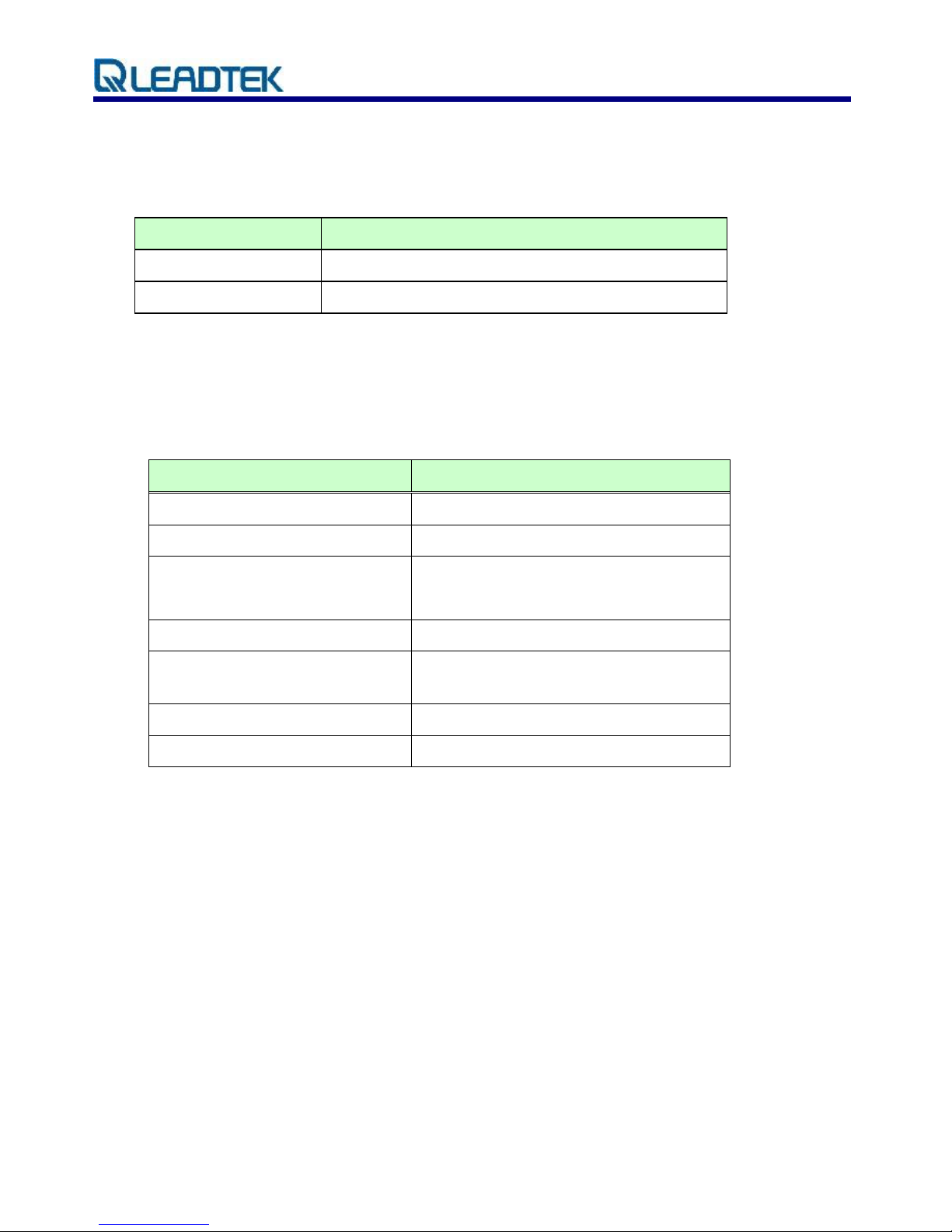
Revision History:
Revision
Release Date
Issuer
Change Description
1.0
2008/10/06
J. Lee
LR9101LR9101X
1.1
2008/12/25
J. Lee
Modify the power consumption
1.2
2009/03/17
J. Lee
Upgrade to FW3.5 and add the RoHS soldering profile
1.3
2009/09/15
J. Lee
Modify the pin assignment
1.4
2009/09/30
S. Liao
Modify the pin assignment
Revision History:
Revision
Release Date
Issuer
Change Description
1.0
2008/10/06
J. Lee
LR9101LR9101X
1.1
2008/12/25
J. Lee
Modify the power consumption
1.2
2009/03/17
J. Lee
Upgrade to FW3.5 and add the RoHS soldering profile
1.3
2009/09/15
J. Lee
Modify the pin assignment
Page 2

© 2009 Leadtek Research Inc. All rights reserved. Page 1/19
Leadtek Confidential - Information is subject to change without prior notice.
LR9101X Specifications Sheet Rev. 1.3
1. Introduction
The Leadtek LR9101X module is a high sensitivity, high gain, low power and very
compact Surface Mount Device (SMD). This 20-channel global positioning system (GPS)
receiver is designed for a broad spectrum of OEM applications and is based on the fast
and deep GPS signal search capabilities of SiRFStarIII GSC3f/LPx architecture,
consuming . Leadtek LR9101X is designed to allow quick and easy integration into
GPS-related applications, especially for compact size devices, such as:
PDA, Pocket PC and other computing devices
Fleet Management / Asset Tracking
AVL and Location-Based Services
Hand-held Device for Personal Positioning and Navigation
1.1 Features
1.1.1 Hardware and Software
Based on the high performance features of the SiRFStar III GSC3f/LPx chipset.
Built-in high gain amplifier and bandpass filter
RoHS compliant (lead-free)
Compact module size for easy integration: 15x14x2.8 mm (590.6x551.2x110.2 mil).
SMT pads allow for fully automatic assembly processes equipment and reflow soldering
SiRFLocTM Client AGPS support
1.1.2 Performance
Cold/Warm/Hot Start Time: 35 / 35 / 1 sec.
Reacquisition Time: 0.1 second
RF Metal Shield for best performance in noisy environments
Multi-path Mitigation Hardware
Enhanced Navigation Performance
Improved Jamming Mitigation
Improved Ephemeris Availability
Page 3

© 2009 Leadtek Research Inc. All rights reserved. Page 2/19
Leadtek Confidential - Information is subject to change without prior notice.
LR9101X Specifications Sheet Rev. 1.3
1.1.3 Interface
TTL level serial port for GPS communications interface
Protocol: NMEA-0183/SiRF Binary (default NMEA)
Baud Rate: 4800 bps
1.2 Advantages
Ideal for compact size devices
Data / Power / RF through surface mount pads
Cost saving through elimination of RF and board to board digital connectors
Flexible and cost effective hardware design for different application requirements
Secure SMD PCB mounting method
Page 4

© 2009 Leadtek Research Inc. All rights reserved. Page 3/19
Leadtek Confidential - Information is subject to change without prior notice.
LR9101X Specifications Sheet Rev. 1.3
2. Technical specifications
2.1. Module architecture
1.20 VDC
SiRF GSC3f/LPx
9101X Block Diagram
Page 5

© 2009 Leadtek Research Inc. All rights reserved. Page 4/19
Leadtek Confidential - Information is subject to change without prior notice.
LR9101X Specifications Sheet Rev. 1.3
2.2. Hardware Features
Based on the high performance features of the SiRFStarIII GSC3f/LPx chipset
Built-in high gain amplifier and bandpass filter
Compact module size for easy integration: 15x14x2.8 mm (590.6x551.2x110.2 mil)
SMT pads allow for fully automatic assembly processes equipment and reflow soldering
RoHS compliant (lead-free)
2.3. Software Features
The firmware used on Leadtek 9101X module is GSW3.5, the software for SiRFStarIII
low power single chipset receivers and its features include:
Excellent sensitivity
High configurability
I Hz position update rate
Supports use of satellite-based augmentation systems like the US WAAS or European
EGNOS system
Real-time Operating System (RTOS) friendly
Capable of outputting either NMEA(default) or SiRF proprietary binary protocols
Designed to accept custom user tasks executed on the integrated ARM7TDM1
processor
Runs in full power operation (default) or optional power saving modes
Enhanced Navigation Performance
Improved Jamming Mitigation
Improved Ephemeris Availability
Default configuration is as follows:
Item
Description
Core of firmware
SiRF GSW3.5
Baud rate
4800 bps
Code type
NMEA-0183 ASCII
Datum
WGS-84
Page 6

© 2009 Leadtek Research Inc. All rights reserved. Page 5/19
Leadtek Confidential - Information is subject to change without prior notice.
LR9101X Specifications Sheet Rev. 1.3
Protocol message
GGA(1s), GSA(5s), GSV(5s), RMC(1s),VTG(1s)
Output frequency
1 Hz
2.4. Mechanical specification
The Physical dimensions of the Leadtek 9101X GPS Module are as follow:
Items
Description
Length
15.0 ± 0.3 mm
Width
14.0 ± 0.3 mm
Height
2.80 ± 0.3 mm
Weight
1.8 g
Page 7
© 2009 Leadtek Research Inc. All rights reserved. Page 6/19
Leadtek Confidential - Information is subject to change without prior notice.
LR9101X Specifications Sheet Rev. 1.3
2.5. Recommended GPS Antenna Specification
This LR9101X receiver is designed for use with passive antenna.
Parameter
Specification
Antenna Type
Right-hand circular polarized passive antenna
Frequency Range
1575.42 ± 1.023 MHz
2.6. Environmental Specification
Item
Description
Operating temperature rang
-30 deg. C to +85 deg. C
Storage temperature range
-55 deg. C to +100 deg. C
Humidity
up to 95% non-condensing or a wet
bulb temperature of +35 deg. C
Altitude
18,000 meters (60,000 feet) max.
Velocity
515 meters/second (1000 knots)
max.
Jerk
20 meters/second3, max.
Acceleration
4g, max.
2.7. ESD Specification
Air Discharge: 2 ; 4 ; 8KV ( direct )
Contact Discharge: 2 ; 4 KV ( direct / indirect )
Page 8
© 2009 Leadtek Research Inc. All rights reserved. Page 7/19
Leadtek Confidential - Information is subject to change without prior notice.
LR9101X Specifications Sheet Rev. 1.3
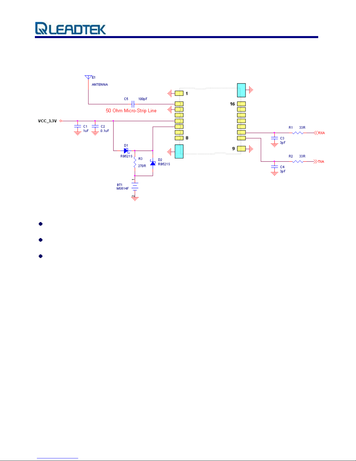
2.8. Reference design
All ground pads attach directly to ground plane by way of via.
All components are reference only.
Recommendation for the external antenna: antennas over 16dB.
Page 9

© 2009 Leadtek Research Inc. All rights reserved. Page 8/19
Leadtek Confidential - Information is subject to change without prior notice.
LR9101X Specifications Sheet Rev. 1.3
3. Performance Characteristics
3.1. Position and velocity accuracy
Accuracy
Position
10 meters, 2D RMS
5 meters 2D RMS, WAAS corrected
<5meters(50%)
Velocity
0.1 meters/second
Time
1 microsecond synchronized to GPS time
3.2. Dynamic constrains
Dynamic
Conditions
Altitude
18,000 meters (60,000 feet) max.
Velocity
515 meters/second (1000 knots) max.
Acceleration
4g, max.
Jerk
20 meters/second3, max.
3.3. Acquisition time 1
Mode
Leadtek 9101X
GPS Module
TTFF Hot
(valid almanac, position, time & ephemeris)
1 s
TTFF Warm
(valid almanac, position, & time)
35 s
TTFF Cold
(valid almanac)
35 s
re-acquisition
(<10 s obstruction with valid almanac, position,
time & ephemeris)
100 ms
Note 1: Open Sky and Stationary Environments.
Page 10
© 2009 Leadtek Research Inc. All rights reserved. Page 9/19
Leadtek Confidential - Information is subject to change without prior notice.
LR9101X Specifications Sheet Rev. 1.3
3.4. Timing 1PPS output
The 1PPS pulse width is 1 μs, this 1PPS is NOT suited to steer various oscillators
(timing receivers, telecommunications system, etc).
3.5. Sensitivity
Parameter
Description
Tracking Sensitivity
-159 dBm
Acquisition Sensitivity
-155 dBm
3.6. Battery backup (SRAM/RTC backup)
During ‘Powered down’ condition, the SRAM and RTC (Real Time Clock may be kept
operation by supplying power from VBATT. The Leadtek 9101X GPS module can
accept slow VBATT supply rise time (unlike many other SiRFstarII based receivers) due
to an on-board voltage detector.
3.7. Differential aiding
3.7.1. Differential GPS (DGPS) Optional
DGPS specification improves the Leadtek 9101X GPS Module horizontal position
accuracy to <4M 2dRMS.
3.7.2. Satellite Based augmentation System (WASS/EGONS) Optional
The Leadtek 9101X GPS Module is capable of receive SBAS(WASS and EGONS)
differential corrections. SBAS improves horizontal position accuracy by correcting GPS
signal errors caused by ionospheric Disturbances, timing and satellite orbit errors.
Both SBAS and DGPS should improve position accuracy. However, other factors can
affect accuracy, such as GDOP, multipath, distance from DGPS reference station and
latency of corrections.
Page 11

© 2009 Leadtek Research Inc. All rights reserved. Page 10/19
Leadtek Confidential - Information is subject to change without prior notice.
LR9101X Specifications Sheet Rev. 1.3
4. Hardware Interface Power supply
Parameter
Leadtek 9101X GPS Module
Input voltage
3.2~ 5.0 VDC
Current (typ.) at full power (3.3V)
33mA
Battery backup voltage
1.5~5.0 VDC
4.1. Power Consumption
Status
Power Consumption
Acquisitioning
33 mA
Tracking
33 mA
Page 12

© 2009 Leadtek Research Inc. All rights reserved. Page 11/19
Leadtek Confidential - Information is subject to change without prior notice.
LR9101X Specifications Sheet Rev. 1.3
4.2. Specifications
4.2.1. Pin Positions
Page 13

© 2009 Leadtek Research Inc. All rights reserved. Page 12/19
Leadtek Confidential - Information is subject to change without prior notice.
LR9101X Specifications Sheet Rev. 1.3
4.2.2. Pin Assignment
PIN
Name
Type
Description
1
RF_Gnd
PWR
RF Ground
2
RF_IN
RF
RF input
3
VSS
PWR
Ground
4
RESETN
I
System reset (active low); In normal operation this pad
should be left floating. Active pull-up is not recommended
5
VCC_IN
PWR
3.2 ~ 5.0 VDC input
6
VSTBY
PWR
1.5 ~ 5.0 VDC RTC backup battery supply
7
RXB
I
TTL level asynchronous input for UART B. If not used,
keep floating
8
TXB
O
TTL level asynchronous output for UART B. If not used,
keep floating
9
GND
PWR
Ground
10
TXA
O
TTL level asynchronous output for UART A
11
RXA
I
TTL level asynchronous input for UART A
12
NC
Not connected, keep floating
13
NC
Not connected, keep floating
14
TIMEMARK
O
1 PPS time mark output. If not used, keep floating
15
NC
Not connected, keep floating
16
GPS Status
O
*Please refer to the diagram below. If not used, keep
floating
Page 14

© 2009 Leadtek Research Inc. All rights reserved. Page 13/19
Leadtek Confidential - Information is subject to change without prior notice.
LR9101X Specifications Sheet Rev. 1.3
5. Software interface
The host serial I/O port of the module’s serial data interface supports full duplex
communication between the module and the user. The default serials are shown in Table
5-1.
Port
Protocol
Description
Port A
NMEA 0183 4800 bps
GGA(1s), GSA(5s), GSV(5s), RMC(5s), VTG(1s)
Port B
N/A
N/A
Table 5-1 Leadtek 9101X GPS module default baud rates
5.1. NMEA output messages
The output NMEA (0183 v3.0) messages for the receiver are listed in Table 5-2. A complete
description of each message is contained in the SiRF NMEA reference manual.
Option
Description
GGA
Time, position, and fix related data for a GPS receiver.
GLL
Latitude and longitude of present position, time of position fix and
status.
GSA
GPS receiver operating mode, satellites used in the position
solution,
and DOP values.
GSV
The number of GPS satellites in view satellite ID numbers,
elevation, azimuth, and SNR values.
RMC
Time, date, position, course and speed data provided by the GPS
receiver.
VTG
The actual course and speed relative to the ground.
Table 5-2 NMEA-0183 Output messages
5.2. SiRF binary
A complete description of each binary message is contained in the Leadtek SiRF Binary
Protocol reference manual.
Page 15
© 2009 Leadtek Research Inc. All rights reserved. Page 14/19
Leadtek Confidential - Information is subject to change without prior notice.
LR9101X Specifications Sheet Rev. 1.3
6. Mechanical drawing and footprint
Items
Description
Length
15.0 ± 0.3 mm (590.6 ± 12 mil)
Width
14.0 ± 0.3 mm (551.2 ± 12 mil)
Height
2.80 ± 0.3 mm (110.2 ± 12 mil)
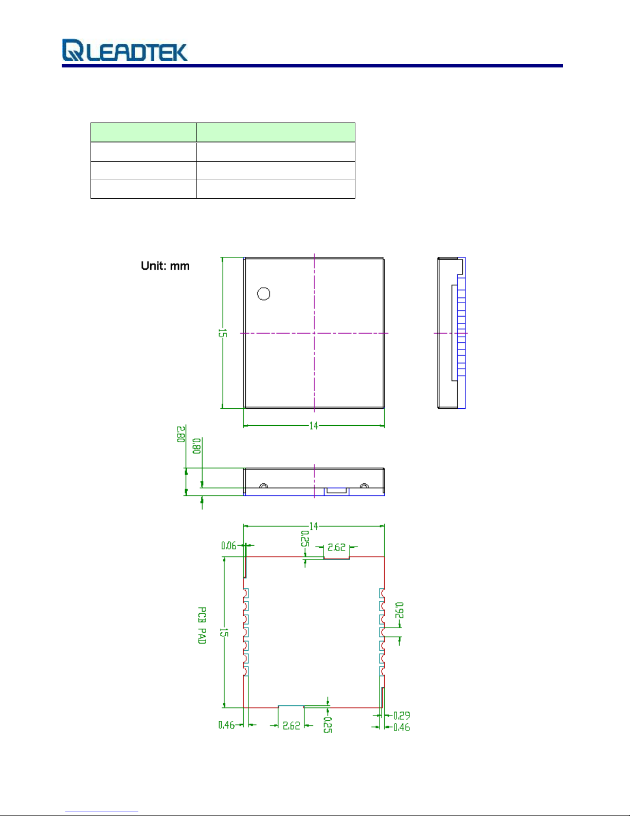
6.1. Outline Drawing
Page 16

© 2009 Leadtek Research Inc. All rights reserved. Page 15/19
Leadtek Confidential - Information is subject to change without prior notice.
LR9101X Specifications Sheet Rev. 1.3
6.2. Recommended footprint ( Top view )
.
Note: 1. Tolerance of recommended pad: 1.87 * 0.92 (+/- 0.1 mm )
2. Recommended pad for pin 9 is 2.3 * 1.5 mm ( +/- 0.1 mm )
7. Application Notes
LR9101X is a compact-sized GPS module, specific for patch antenna design. It has the
pin- to-pin compatibility with LR9102, which is specific for active antenna design.
It requires additional power supply with 3.3V externally, in case of using active antenna.
Page 17

© 2009 Leadtek Research Inc. All rights reserved. Page 16/19
Leadtek Confidential - Information is subject to change without prior notice.
LR9101X Specifications Sheet Rev. 1.3
8. Automated manufacturing components
8.1. 8.1 Reel and taping specifications
(Unit: mm)
Page 18
© 2009 Leadtek Research Inc. All rights reserved. Page 17/19
Leadtek Confidential - Information is subject to change without prior notice.
LR9101X Specifications Sheet Rev. 1.3
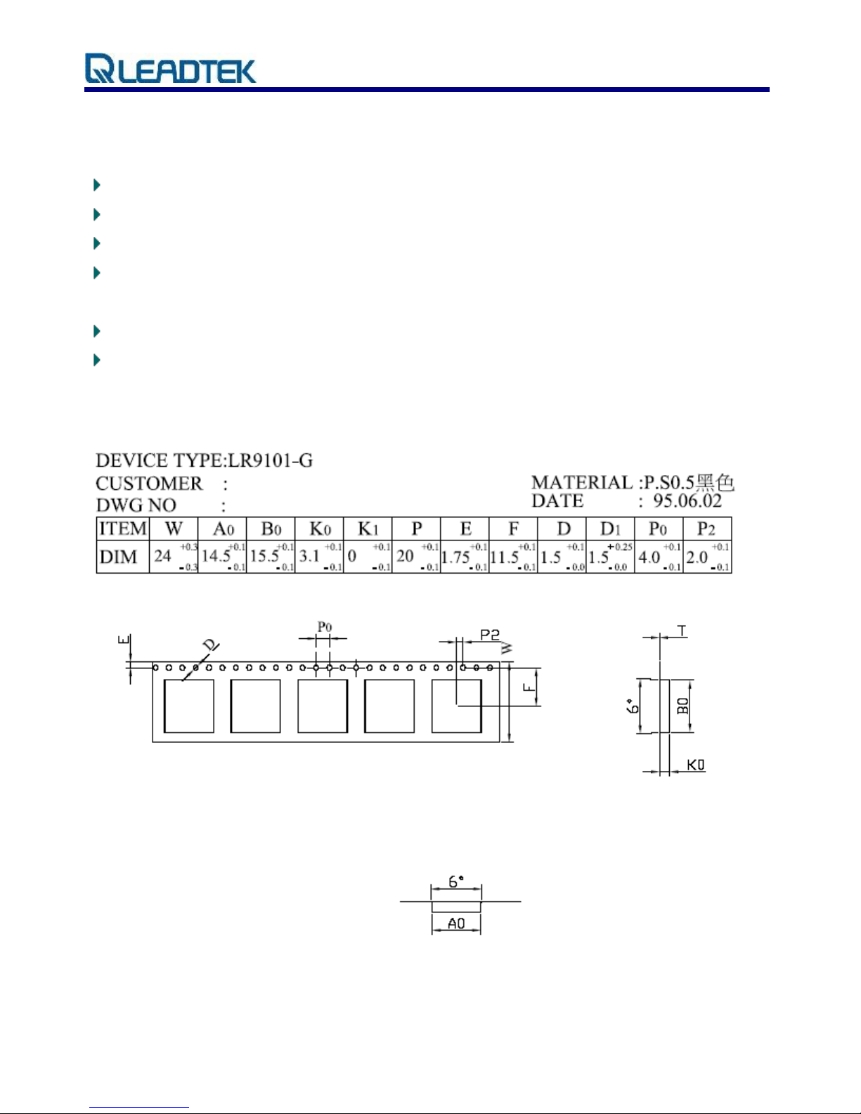
8.2. Polystyrene Alloy Taping Specifications
10 sprocket hole pitch cumulative tolerance ±0.20mm
Carrier camber is within 1mm in 100mm
A0 and B0 measured on a plane 0.3mm above the bottom of the pocket
K0 measured from a plane on the inside bottom of the pocket to the top surface of the
carrier
All dimensions meet EIA-481-2 requirements
22” 1R= 63M 3000PCS 13”21M 1000PCS
8.3. Polystyrene Alloy Taping Drawing
Page 19

© 2009 Leadtek Research Inc. All rights reserved. Page 18/19
Leadtek Confidential - Information is subject to change without prior notice.
LR9101X Specifications Sheet Rev. 1.3
9. RoHS soldering profile
9.1 Reflow profile
High quality, low defect soldering requires identifying the optimum temperature profile for
reflowing the solder paste. To have the correct profile assures components, boards, and
solder joints are not damaged and reliable solder connection is achievable. Profiles are
essential for establishing and maintaining processes. You must be able to repeat the profile
to achieve process consistency. The heating and cooling rise rates must be compatible with
the solder paste and components. The amount of time that the assembly is exposed to
certain temperatures must first be defined and then maintained.
Average ramp-up rate
3℃/second max.
Preheat (Tsmax – Tsmin, ts)
150~200℃ ; 60~180seconds
Time maintained above ( TL, tL)
217℃ ; 60~150seconds
Peak Temperature (Tp)
255~260℃ ; 10~20seconds
Ramp-down rate
6℃/second max.
Time 25℃ to Peak Temperature
8 minutes max.
Maximum number of reflow cycles
≤3
Page 20

© 2009 Leadtek Research Inc. All rights reserved. Page 19/19
Leadtek Confidential - Information is subject to change without prior notice.
LR9101X Specifications Sheet Rev. 1.3
9.2 Storage & baking condition
1. Calculated shelf life in sealed bag: 6 months at <40℃ and <90% relative humidity(RH).
2. After bag is opened, devices that will be subjected to reflow soldering or other high
temperature process must be:
a. Mounted within: 24 hours of factory conditions ≤30℃ /60% RH, or
b. Stored at <10% RH under the protection against humidity and static electricity
3. Devices require bake before mounting, if:
a. Humidity indicator Card is >60% when read at 23±5℃
b. 2a or 2b not met
4. If baking is required, devices may be baked for 24 hours at 125±5℃
Note: if device containers cannot be subjected to high temperature or if shorter bake times
are desired, reference IPC/JEDEC J-STD-020 for bake procedure
TCXO
16.369M
Hz
 Loading...