

Page 1

LR9101LP
GPS Module
i
Page 2

1. INTRODUCTION..................................................................................................................1
1.1. F
1.2. A
EATURES.........................................................................................................................1
DVANTAGES...................................................................................................................2
2. TECHNICAL SPECIFICATIONS.......................................................................................2
2.1. M
2.2. H
2.3. S
2.4. M
2.5. R
2.6. E
2.7. P
2.8. R
ODULE ARCHITECTURE..................................................................................................2
ARDWARE FEATURES.....................................................................................................3
OFTWARE FEATURES ......................................................................................................3
ECHANICAL SPECIFICATION ...........................................................................................3
ECOMMENDED GPS ANTENNA SPECIFICATION ..............................................................4
NVIRONMENTAL SPECIFICATION.....................................................................................4
RODUCT COMPLIANCE.....................................................................................................5
EFERENCE DESIGN ..........................................................................................................7
3. PERFORMANCE CHARACTERISTICS...........................................................................8
3.1. P
3.2. D
3.3. A
3.4. T
3.5. S
3.6. B
3.7. D
OSITION AND VELOCITY ACCURACY ................................................................................8
YNAMIC CONSTRAINS.....................................................................................................8
CQUISITION TIME
IMING 1PPS OUTPUT.......................................................................................................9
ENSITIVITY .....................................................................................................................9
ATTERY BACKUP (SRAM/RTC BACKUP) .......................................................................9
IFFERENTIAL AIDING ......................................................................................................9
1
..........................................................................................................8
3.7.1. Differential GPS (DGPS): Option......................... ... ................................... .............9
3.7.2. Satellite Based augmentation System (WASS/EGONS): Option..............................9
4. HARDWARE INTERFACE POWER SUPPLY...............................................................10
4.1. S
PECIFICATIONS.............................................................................................................. 10
4.1.1. Pin Positions ..........................................................................................................10
4.1.2. Pin Assignment.......................................................................................................11
5. SOFTWARE INTERFACE.................................................................................................12
5.1. NMEA
5.2. S
OUTPUT MESSAGES.............................................................................................12
IRF BINARY ..................................................................................................................12
6. MECHANICAL DRAWING AND FOOTPRINT............................................................13
6.1. O
6.2. R
UTLINE DRAWING ........................................................................................................13
ECOMMENDED FOOTPRINT (BOTTOM VIEW) .................................................................14
7. AUTOMATED MANUFACTURING COMPONENTS ..................................................15
7.1. R
7.2. P
7.3. P
EEL AND TAPING SPECIFICATIONS.................................................................................15
OLYSTYRENE ALLOY TAPING SPECIFICATIONS.............................................................16
OLYSTYRENE ALLOY TAPING DRAWING ......................................................................16
8. ROHS COMPLIANT INFORMATION............................................................................17
8.1. R
OHS SOLDERING PROFILE.............................................................................................17
Reflow Profile.........................................................................................................................17
GLOSSARY..................................................................................................................................18
ii
Page 3

LR9101LP Specifications Sheet Rev. 0.1
1. Introduction
The Leadtek GPS 9101LP module (LR9101LP) is a high sensitivity, high gain, low power and
very compact Surface Mount Device (SMD). This 20-channel global positioning system (GPS)
receiver is designed for a broad spectrum of OEM applications and is based on the fast and deep
GPS signal search capabilities of SiRF StarIII™ single chip architecture. Leadtek GPS 9101LP is
designed to allow quick and easy integration into GPS-related applications, especially for
compact size devices, such as:
PDA, Pocket PC and other computing devices
Fleet Management / Asset Tracking
AVL and Location-Based Services
Hand-held Device for Personal Positioning and Navigation
1.1. Features
Hardware and Software
Based on the high performance features of the SiRF Star III/LP single chip
Built-in high gain amplifier and band pass filter
RoHS compliant (lead-free)
Compact module size for easy integration: 15x14x2.8 mm (590.6x551.2x110.2 mil).
SMT pads allow for fully automatic assembly processes equipment and reflow soldering
SiRFLocTM Client AGPS support
Performance
Cold/Warm/Hot Start Time: 42 / 38 / 1 sec.
Reacquisition Time: 0.1 second
RF Metal Shield for best performance in noisy environments
Multi-path Mitigation Hardware
© 2006 Leadtek Research Inc. All rights reserved. Page 1/21
Preliminary Confidential - Information is subject to change without prior notice.
Page 4
LR9101LP Specifications Sheet Rev. 0.1
Interface
TTL level serial port for GPS communications interface
Protocol: NMEA-0183/SiRF Binary (default NMEA)
Baud Rate: 9600, 19200 bps (default 9600)
1.2. Advantages
Ideal for compact size devices
Data / Power / RF through surface mount pads
Cost saving through elimination of RF and board to board digital connectors
Flexible and cost effective hardware design for different application requirements
Secure SMD PCB mounting method
2. Technical specifications
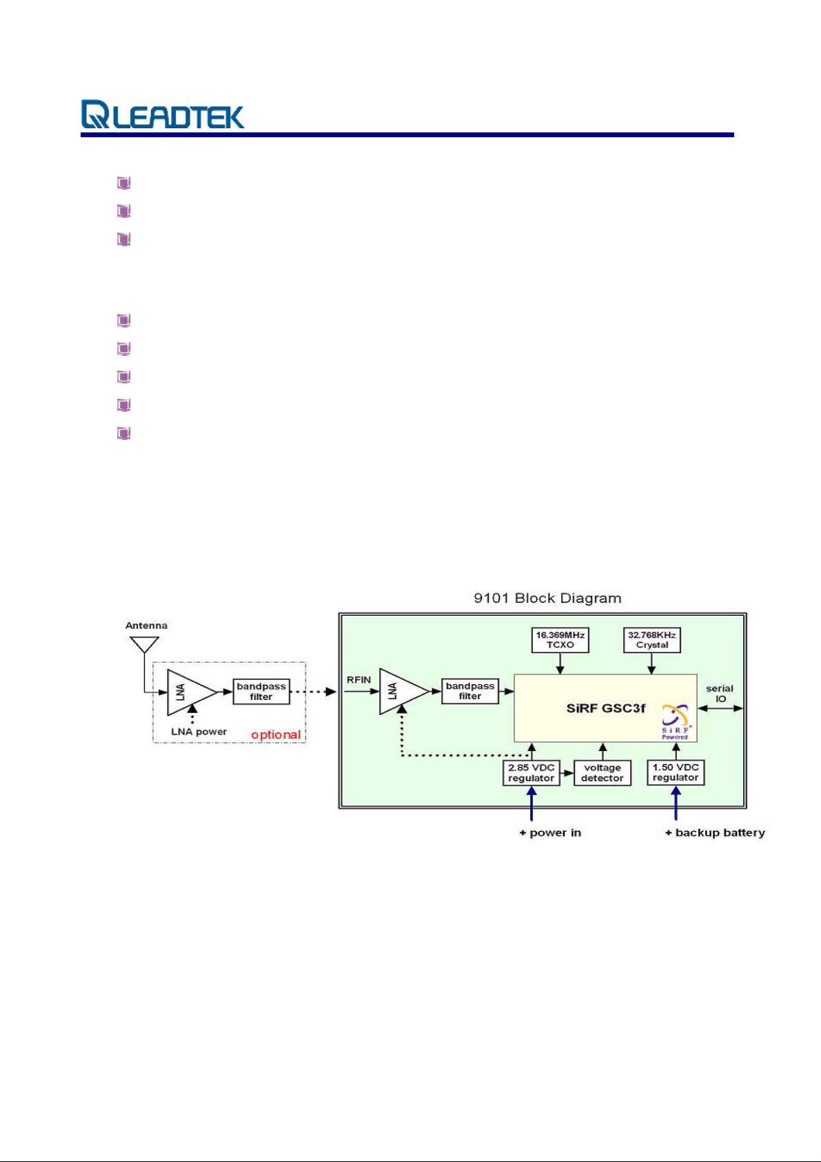
2.1. Module architecture
© 2006 Leadtek Research Inc. All rights reserved. Page 2/21
Preliminary Confidential - Information is subject to change without prior notice.
Page 5

LR9101LP Specifications Sheet Rev. 0.1
2.2. Hardware Features
Based on the high performance features of the SiRF StarIII/LP single chip
Built-in high gain amplifier and band pass filter
Compact module size for easy integration: 15x14x2.8 mm (590.6x551.2x110.2 mil)
SMT pads allow for fully automatic assembly processes equipm en t an d reflow soldering
RoHS compliant (lead-free)
2.3. Software Features
The firmware used on Leadtek 9101LP module is GSW3, the software for SiRF StarIII/LP
receivers, and the default configuration is as following description:
Item Description
Core of firmware SiRF GSW3
Baud rate 9600, 19200 bps (default 9600)
Code type NMEA-0183 ASCII
Datum WGS-84
Protocol message GGA, GSA, GSV, RMC,VTG
Output frequency 1 Hz
2.4. Mechanical specification
The Physical dimensions of the Leadtek 9101LP GPS Module are as follow:
Items Description
Length 15.0 ± 0.1 mm (590.6 ± 4 mil)
Width 14.0 ± 0.1 mm (551.2 ± 4 mil)
Height 2.80 ± 0.3 mm (110.2 ± 12 mil)
Weight 1g
© 2006 Leadtek Research Inc. All rights reserved. Page 3/21
Preliminary Confidential - Information is subject to change without prior notice.
Page 6

LR9101LP Specifications Sheet Rev. 0.1
2.5. Recommended GPS Antenna Specification
This GPS 9101LP receiver is designed for use with passive antenna.
Parameter Specification
Antenna Type Right-hand circular polarized passive antenna
Frequency Range 1575.42 ± 1.023 MHz
2.6. Environmental Specification
Item Description
Operating temperature rang -30 deg. C to +85 deg. C
Storage temperature range -40 deg. C to +85 deg. C
Humidity Up to 95% non-condensing or a wet
bulb temperature of +35 deg. C
Altitude 18,000 meters (60,000 feet) max.
Velocity
515 meters/second (1000 knots)
max.
Jerk 20 meters/second3, max.
Acceleration
4g, max.
© 2006 Leadtek Research Inc. All rights reserved. Page 4/21
Preliminary Confidential - Information is subject to change without prior notice.
Page 7
LR9101LP Specifications Sheet Rev. 0.1
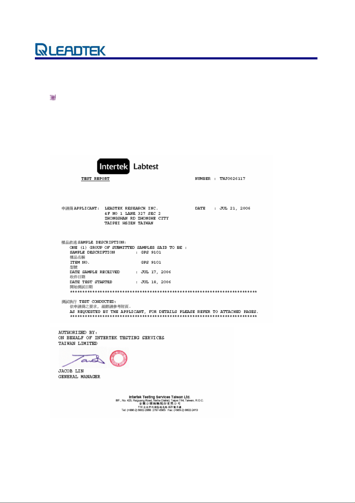
2.7. Product compliance
RoHS: Restriction of Hazardous Substances (RoHS) directive will come into force on 1st
July 2006; all electronic products sold in the EU must be free of hazardous materials, such as
lead. Leadtek is fully committed to being one of the first to introduce lead-free GPS products
while maintaining backwards compatibility and focusing on a continuously high level of
product and manufacturing quality.
© 2006 Leadtek Research Inc. All rights reserved. Page 5/21
Preliminary Confidential - Information is subject to change without prior notice.
Page 8

LR9101LP Specifications Sheet Rev. 0.1
FCC/CE: The Federal Communications Commission (FCC) is an independent United
States government agency, directly responsible to Congress. The FCC is charged with
regulating interstate and international communications by radio, television, wire, satellite
and cable. The FCC’s jurisdiction covers the 50 states, the District of Columbia, and U.S.
possessions.
Please note that the compliances of this device are for this SMD module itself only.
The complete system compliance must be examined and certified whenever you
put this SMD inside.
© 2006 Leadtek Research Inc. All rights reserved. Page 6/21
Preliminary Confidential - Information is subject to change without prior notice.
Page 9

LR9101LP Specifications Sheet Rev. 0.1
2.8. Reference design
All ground pads attach directly to ground plane by way of via.
All components are reference only
© 2006 Leadtek Research Inc. All rights reserved. Page 7/21
Preliminary Confidential - Information is subject to change without prior notice.
Page 10

LR9101LP Specifications Sheet Rev. 0.1
3. Performance Characteristics
3.1. Position and velocity accuracy
10 meters, 2D RMS
Position
Accuracy
Velocity 0.1 meters/second
Time 1 microsecond synchronized to GPS time
3.2. Dynamic constrains
Altitude 18,000 meters (60,000 feet) max.
Dynamic
Conditions
Velocity 515 meters/second (1000 knots) max.
Acceleration 4g, max.
Jerk 20 meters/second
3.3. Acquisition time 1
Mode
5 meters 2D RMS, WAAS corrected
< 5meters (50%).
3
, max.
Leadtek 9101LP GPS
Module
TTFF Hot
1 s
(valid almanac, position, time & ephemeris)
TTFF Warm
38 s
(valid almanac, position, & time)
TTFF Cold
42 s
(valid almanac)
re-acquisition
(<10 s obstruction with valid almanac, position,
time & ephemeris)
Note 1: Open Sky and Stationary Environments.
100 ms
© 2006 Leadtek Research Inc. All rights reserved. Page 8/21
Preliminary Confidential - Information is subject to change without prior notice.
Page 11

LR9101LP Specifications Sheet Rev. 0.1
3.4. Timing 1PPS output
The 1PPS pulse width is 1 µs, this 1PPS is NOT suited to steer various oscillators (timing
receivers, telecommunications system, etc).
3.5. Sensitivity
Parameter Description
Tracking Sensitivity -159 dBm
Acquisition Sensitivity -155 dBm
3.6. Battery backup (SRAM/RTC backup)
During ‘Powered down’ condition, the SRAM and RTC (Real Time Clock may be kept
operation by supplying power from VBATT. The Leadtek 9101LP GPS module can accept slow
VBATT supply rise time (unlike many other SiRF StarII based receivers) due to an on-board
voltage detector.
3.7. Differential aiding
3.7.1. Differential GPS (DGPS): Option
DGPS specification improves the Leadtek 9101LP GPS Module horizontal position accuracy to
less than 4M 2dRMS.
3.7.2. Satellite Based augmentation System (WASS/EGONS): Option
The Leadtek 9101LP GPS Module is capable of receive SBAS (WASS and EGONS) differential
corrections. SBAS improves horizontal position accuracy by correcting GPS signal errors caused
by ionosphere Disturbances, timing and satellite orbit errors.
Both SBAS and DGPS should improve position accuracy. However, other factors can affect
accuracy, such as GDOP, multi-path, distance from DGPS reference station and latency of
corrections.
© 2006 Leadtek Research Inc. All rights reserved. Page 9/21
Preliminary Confidential - Information is subject to change without prior notice.
Page 12

LR9101LP Specifications Sheet Rev. 0.1
4. Hardware Interface Power supply
Parameter Leadtek 9101LP GPS Module
Input voltage
Current (typ.) at full power (3.3V) 49mA
Battery backup voltage 1.65~5.0 VDC
4.1. Specifications
4.1.1. Pin Positions
3.2 ~ 5.0 VDC
© 2006 Leadtek Research Inc. All rights reserved. Page 10/21
Preliminary Confidential - Information is subject to change without prior notice.
Page 13

LR9101LP Specifications Sheet Rev. 0.1
4.1.2. Pin Assignment
PIN Name Type Description
1 RF GND RF RF Ground
2 RF IN RF RF input
3 VSS PWR Ground
4 RESETN I System reset (active low); In normal operation this pad should
be left floating. Active pull-up is not recommended
5 VCC IN PWR 3.2 ~ 5.0 VDC input
6 VSTBY PWR 1.65 ~ 5.0 VDC RTC backup battery supply
7 RXB I TTL level asynchronous input for UART B
8 TXB O TTL level asynchronous output for UART B
9 GND 2 Ground
10 TXA O TTL level asynchronous output for UART A
11 RXA I TTL level asynchronous input for UART A
12 GPIO1 I Reserved, general purpose IO
13 GPIO14 I Reserved, general purpose IO
14 TIMEMARK O 1 PPS time mark output
15 GPIO13 I Reserved, general purpose IO
16 GPIO15 I Reserved, general purpose IO
Note 2: There are two more shielding case ground pads, please refer the recommended
footprint.
© 2006 Leadtek Research Inc. All rights reserved. Page 11/21
Preliminary Confidential - Information is subject to change without prior notice.
Page 14

LR9101LP Specifications Sheet Rev. 0.1
5. Software interface
The host serial I/O port of the module’s serial data interface supports full duplex communication
between the module and the user. The default serials are shown in Table 5-1.
Port Protocol Description
Port A NMEA 0183, 9600 bps GGA, GSA, GSV, RMC, VTG
Port B
5.1. NMEA output messages
The output NMEA (0183 v3.0) messages for the receiver are listed in Table 5-2. A complete
N/A N/A
Table 5-1 Leadtek 9101LP GPS module default baud rates
description of each message is contained in the SiRF NMEA reference manual.
5.2. SiRF binary
A complete description of each binary message is contained in the Leadtek SiRF Binary Protocol
reference manual.
© 2006 Leadtek Research Inc. All rights reserved. Page 12/21
Preliminary Confidential - Information is subject to change without prior notice.
Page 15

LR9101LP Specifications Sheet Rev. 0.1
6. Mechanical drawing and footprint
Items Description
6.1. Outline Drawing
Length 15.0 ± 0.1 mm (590.6 ± 4 mil)
Width 14.0 ± 0.1 mm (551.2 ± 4 mil)
Height 2.80 ± 0.3 mm (110.2 ± 12 mil)
© 2006 Leadtek Research Inc. All rights reserved. Page 13/21
Preliminary Confidential - Information is subject to change without prior notice.
Page 16
LR9101LP Specifications Sheet Rev. 0.1
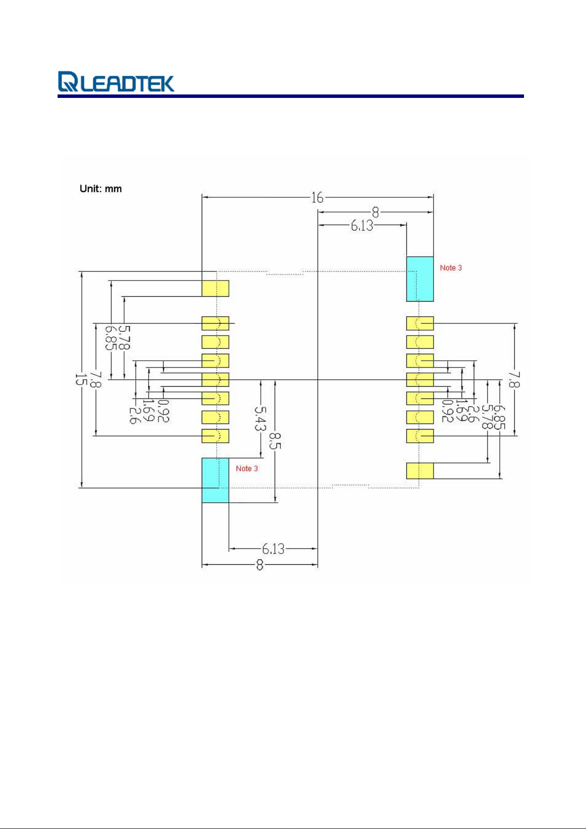
6.2. Recommended footprint (Bottom view)
Note 3: These two shielding case ground pads should attach directly to a ground plane.
© 2006 Leadtek Research Inc. All rights reserved. Page 14/21
Preliminary Confidential - Information is subject to change without prior notice.
Page 17
LR9101LP Specifications Sheet Rev. 0.1
7. Automated manufacturing components
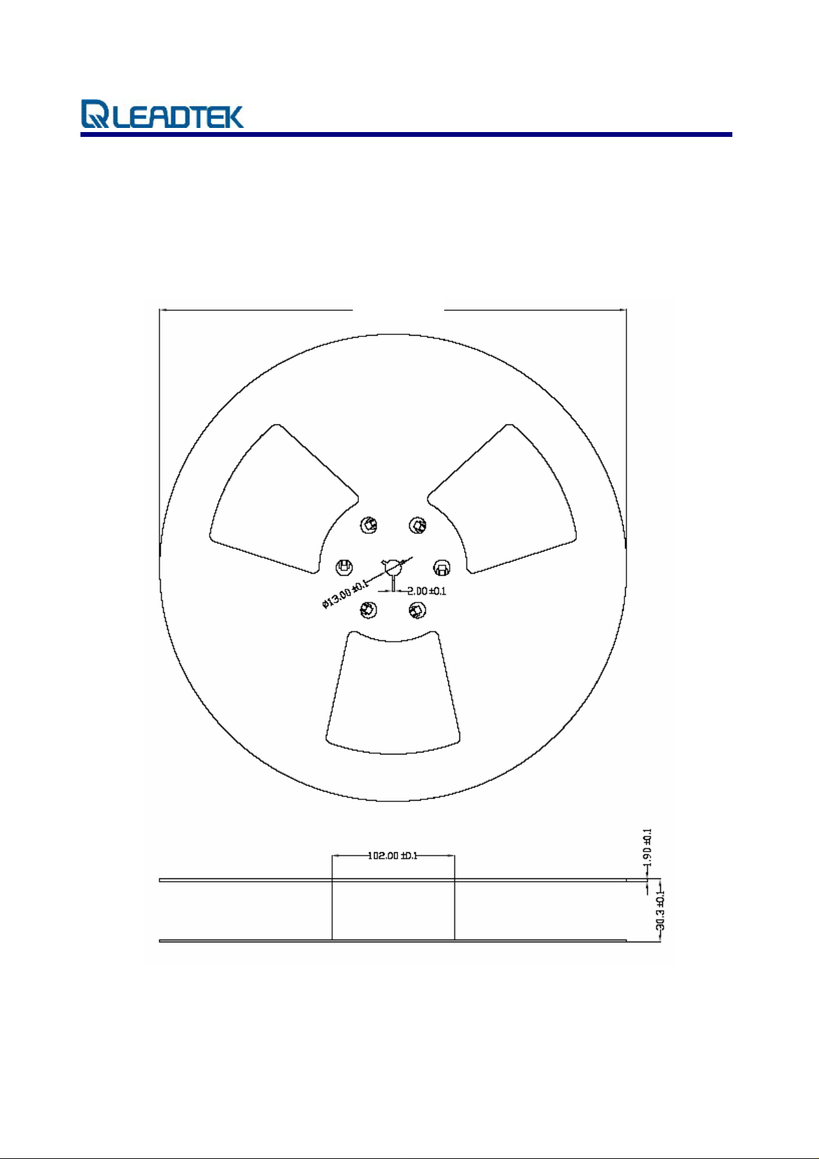
7.1. Reel and taping sp ecifications
(Unit: mm)
380.00±0.1
© 2006 Leadtek Research Inc. All rights reserved. Page 15/21
Preliminary Confidential - Information is subject to change without prior notice.
Page 18

LR9101LP Specifications Sheet Rev. 0.1
7.2. Polystyrene Alloy Taping Specifications
10 sprocket hole pitch cumulative tolerance ±0.20mm
Carrier camber is within 1mm in 100mm
A0 and B0 measured on a plane 0.3mm above the bottom of the pocket
K0 measured from a plane on the inside bottom of the pocket to the top surface of the carrier
All dimensions meet EIA-481-2 requirements
22” 1R= 63M 3000PCS 13”21M 1000PCS
7.3. Polystyrene Alloy Taping Draw ing
© 2006 Leadtek Research Inc. All rights reserved. Page 16/21
Preliminary Confidential - Information is subject to change without prior notice.
Page 19

LR9101LP Specifications Sheet Rev. 0.1
8. RoHS compliant information
By July 1, 2006, all electronic products sold in the EU must be free of hazardous materials, such as
lead. Leadtek is filly committed to being one of the fir st to introduce lead-free GPS Products while
maintaining backwards compatibility and focusing on a continuously high level of product and
manufacturing quality.
8.1. RoHS soldering profile
Reflow Profile
High quality, low defect soldering requires identifying the optimum temperature profile for reflowing
the solder paste. To have the correct profile assures components, boa rds, and solder joints are not
damaged and reliable solder connection is achievable. Profiles are essential for establishing and
maintaining processes. You must be able to repeat the profile to achieve process consist ency. The
heating and cooling rise rates must be compatible with the solder paste and components. The amount
of time that the assembly is exposed to certain temperatures must first be defined and then maintained.
The following is an example of a typical thermal profile.
© 2006 Leadtek Research Inc. All rights reserved. Page 17/21
Preliminary Confidential - Information is subject to change without prior notice.
Page 20

LR9101LP Specifications Sheet Rev. 0.1
Glossary
A-GPS
Assisted GPS or AGPS is a technology that uses an assistance server to cut down t he time needed to
find the location. Although GPS provides excellent position accuracy, position fixes require lines of
sight to the satellites. In regular GPS networks there are only GPS satellites and GPS receivers. In
A-GPS networks, the receiver, being limited in processing power and normally under less than ideal
locations for position fixing, communicates with the assistance server that has high processing power
and access to a reference network. Although dependent on cellular coverage, AGPS processing is
quicker and more efficient than regular GPS.
API
An application programming interface is a set of definitions of the way one piece of computer software
communicates with another. One of the primary purposes of an API is to provide a set of commonly
used functions, such as to draw windows or icons on the screen. Programmers can then take advantage
of the API by making use of its functionality, saving them the task of programming everything from
scratch.
Baud Rate
Is a measure of the signaling rate, which is the number of changes to the transmission media per
second in a modulated signal.
For Example: 250 baud means that 250 signals are transmitted in one second. If each signal carries 4
bits of information then in each second 1000 bits are transmitted. This is abbreviated as 1000 bit/s.
Dead Reckoning
The process of estimating your position by advancing a known position using course, speed, time and
distance to be traveled. It is figuring out where you will be at a certain time if you hold the speed, time
and course you plan to travel.
Differential GPS (DGPS)
An extension of the GPS system that uses land-based radio beacons to transmit position corrections to
GPS receivers. DGPS reduces the effect of selective availability, propagation delay, etc. and can
improve position accuracy to better than 10 meters.
EGNOS
A satellite navigation system being developed by the European Space Agency, the European
Commission, and EUROCONTROL. It is intended to supplement the GPS and GLONASS systems by
reporting on the reliability and accuracy of the signals. According to specifications, horizontal position
accuracy should be better than 7 meters. In practice, the horizontal position accuracy is at the meter
level. It will consist of three geostationary satellites and a network of ground stations.
Similar service is provided in America by the WAAS system. See WAAS.
© 2006 Leadtek Research Inc. All rights reserved. Page 18/21
Preliminary Confidential - Information is subject to change without prior notice.
Page 21

LR9101LP Specifications Sheet Rev. 0.1
European Geostationary Navigation Overlay System
See EGNOS.
LNA
A special type of electronic amplifier or amplifier used in communication systems to amplify very
weak signals captured by an antenna. It is usually located at the antenna and is a key component, which
is placed at the front-end of a receiver system.
Low Noise Amplifier
See LNA.
Multi-path mitigation
Anticipating errors caused when a satellite signal reaches the GPS receiver antenna by more than one
path. Usually caused by one or more paths being bounced or reflected off of structures near the
antenna and occurs to some extent everywhere. The signal which traverses a longer path will yield a
larger pseudo range estimate and increase the er ror.
NMEA
An U.S. standards comm ittee that def ine s data m es s age structure, contents, and protocols to allow the
GPS receiver to communicate with other pieces of electronic equipment.
National Marine Electronics Association
See NMEA.
1PPS
Pulse which is generated once per second. GPS and some radio clocks and related timekeeping gear
have a pulse-per-second or PPS signal that is needed for high accuracy time synchronization. The PPS
signal can be connected in either of two ways, either through the data leads of a serial port or through
the modem control leads. Either way requires conversion of the PPS signal,
Most GPS devices emit an rs-232 serial stream with some kind of timestamp format. Many GPS
devices are small realtime systems with the satellite tracking done at high priority, positioning done at
medium priority, and time output done at low priority. The timestamps often have +- 200 ms of jitter
(variance in delay), and output a PPS signal on the exact second.
SMD
Electronic device components that are mounted directly onto the surface of printed circuit boards
(PCBs). In the industry it has largely replaced the previous construction method of fitting components
with wire leads into holes in the circuit board (also called through-hole technology).
© 2006 Leadtek Research Inc. All rights reserved. Page 19/21
Preliminary Confidential - Information is subject to change without prior notice.
Page 22

LR9101LP Specifications Sheet Rev. 0.1
Surface Mount Device
See SMD.
TCXO
An electronic device that u ses the mechanical resonance of a phy sical crystal to cre ate an electrical
signal with a very precise frequency and can be embedded in integrated circuits. TCXO reduces the
environmental changes of temperature, humidity, and vibration, to keep a stable output frequency.
Temperature Controlled Crystal Oscillator
See TCXO.
Time To First Fix (TTFF)
The time it takes a GPS receiver to find satellites after you first turn it on, when the GPS receiver has
lost memory, or has been moved over 300 miles from its last location. Standard TTFF Timing consists
of:
Mode Requires Timing
Snap Start Hot + Clock + Sat Pos 3 minutes off
Hot Start Warm + Ephemeris 30 minutes off
Warm Start Position Accuracy
Time Accuracy
Almanac
<500 KM
<2 hours
<1 year
Cold Start Nothing N/A
Specifications are typical times assuming good satellite visibility and above threshold signal strengths.
WAAS
A system of satellites and ground stations that provide GPS signal corrections for better position
accuracy. A WAAS-capable receiver can give you a position accuracy of better than three meters, 95
percent of the time. (At this time, the system is still in the development stage and is not fully
operational.) WAAS consists of approximately 25 ground reference stations positioned across the
United States that monitor GPS satellite data. Two master stations, located on either coast, collect data
from the reference stations and create a GPS correction message.
Wide Area Augmentation System
See WAAS.
© 2006 Leadtek Research Inc. All rights reserved. Page 20/21
Preliminary Confidential - Information is subject to change without prior notice.
Page 23

LR9101LP Specifications Sheet Rev. 0.1
Leadtek Research Inc.
18F, 166, Chien-Yi Rd.,
Chung Ho, Taipei
Hsien, Taiwan (235)
©2006 Leadtek Research,
Inc.
All rights reserved.
Version 0.6
Sep/06
© 2006 Leadtek Research Inc. All rights reserved. Page 21/21
Preliminary Confidential - Information is subject to change without prior notice.
 Loading...