

Page 1

K8N/K8N Pro
Socket 754 Motherboards
User’s Manual
Page 2

Copyright © 2003 by Leadtek Research Inc. All rights reserved.
No part of this document may be copied or reproduced in any form or by any
means without the prior written consent of Leadtek Research Inc.
Leadtek makes no warranties with respect to this documentation and disclaims any
implied warranties of merchantability, quality, or fitness for any particular purpose.
The information in this document is subject to change without notice. Leadtek
reserves the right to make revisions to this publication without obligation to notify
any person or entity of any such changes.
WinFast® is a registered trademark of Leadtek Research Inc. Other trademarks or
brand names mentioned herein are trademarks or registered trademarks of their
respective owners.
Leadtek Research Inc.
International Headquarters
18th Fl., 166, Chien-Yi Rd., Chung Ho
Taipei Hsien, Taiwan (235)
Phone: +886 (0)2 8226 5800
Fax: +886 (0)2 8226 5801
http://www.leadtek.com.tw
Email: service@leadtek.com.tw
Leadtek U.S.A.
46732 Lakeview Blvd.
Fremont, CA94538, U.S.A.
Phone: +1 510 490 8076
Fax: +1 510 490 7759
http://www.leadtek.com
Leadtek Research Europe B.V.
Antennestraat 16 1322 AB
Almere, The Netherlands
Phone: +31 (0)36 536 5578
Fax: +31 (0)36 536 2215,
http://www.leatek.nl
WinFast K8N User’s Manual CODE: LR5940/5942
Version A P/N : W0500784
September 2003
Page 3

Table of Contents
1. Introduction ……………………………………………………….. 1
1.1. Specifications ............................................................................ 2
2. Quick Setting ……………………………………………………… 4
2.1. Jumper Position.......................................................................... 4
2.2. Jumper/Connector Listing .......................................................... 5
2.3. Jumper Settings ......................................................................... 6
3. Hardware Setup ……………………………………………………7
3.1. CPU Installation.......................................................................... 7
3.2. Memory Installation .................................................................... 8
3.3. AGP Display Adapter Installation ............................................... 9
3.4. Configuring an Expansion Card ............................................... 10
3.5. Connecting Instructions............................................................ 11
4. BIOS Setup ………………………………………………………. 17
4.1. Main Menu................................................................................ 17
4.2. Standard CMOS Features........................................................ 18
4.3. Advanced BIOS Features ........................................................ 21
4.4. Advanced Chipset Features..................................................... 23
4.5. Integrated Peripherals.............................................................. 25
4.6. Power Management Setup....................................................... 28
4.7. PnP/PCI Configurations ........................................................... 30
4.8. PC Health Status (O.T.S.) ........................................................ 31
4.9. X-BIOS II (Over-Clocking)........................................................ 32
4.10. Load Basic Defaults ................................................................. 32
4.11. Load Best Defaults................................................................... 32
4.12. Set Supervisor/User Password ................................................ 33
4.13. Save & Exit Setup .................................................................... 34
4.14. Exit Without Saving .................................................................. 34
Page 4

5. Driver Installation ……………………………………………….. 35
5.1. Under Windows 2000/XP ......................................................... 35
5.1.1. Installing Chipset Driver.......................................................... 35
5.1.2. Installing GIGA LAN Driver ..................................................... 39
5.1.3. Installing SATA Driver ............................................................. 41
5.2. Installing Speed Gear Over Clock Utility.................................. 44
5.3. Installing DirectX 8.1 ................................................................ 46
5.4. Installing Acrobat Utility ............................................................ 46
6. Speed Gear Operation …………………………………………..47
7. Appendix …………………………………………………………..49
7.1. BIOS Flash Utility ..................................................................... 49
7.2. Troubleshooting Procedures .................................................... 50
7.3. Technical Support ..................................................................... 51
7.4. FCC Statement......................................................................... 51
7.5. Limited Warranty ...................................................................... 52
Page 5

1. Introduction
WinFast K8N is a compelling Desktop solution as a Socket 754/AMD Athlon 64
ATX motherboard.
WinFast K8N, integrating NVIDIA chipset, supports the AMD Athlon 64 processor
whose performance is bound to exceed expectation of both consumer and
corporate users alike. The WinFast K8N also supports PC1600/PC2100/PC2700/
PC3200 DDR memories, and the latest graphics devices through the AGP 3.0 8X
interface; and it supports serial ATA port RAID, IEEE1394, USB2.0 and 6-channel
audio feature.
WinFast K8N Pro integrated eNOVA X-Wall LX64 chipset that offer data security
for your hard disk data.
Accessories:
y Ultra ATA 66/100/133 IDE cable x
1; FDD cable x 1
y User’s manual
y USB module and cable (optional)
y 1 I/O shield
y Driver CD
y 4 x SATA cable
y 1 x two ports 1394 module (K8N)
y 1 x three ports 1394 module
(K8N Pro)
Motherboard Software Pack CD:
y Chipset driver
y GIGA LAN driver
y SATA driver
y Speed Gear II
y AWARD flash utility
y User’s manual
y Technical support request form
1
Page 6
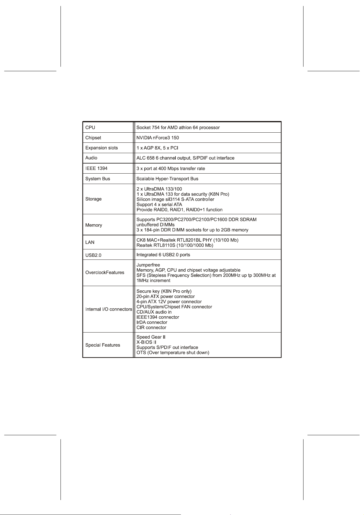
1.1. Specifications
2
Page 7
3
Page 8
2. Quick Setting
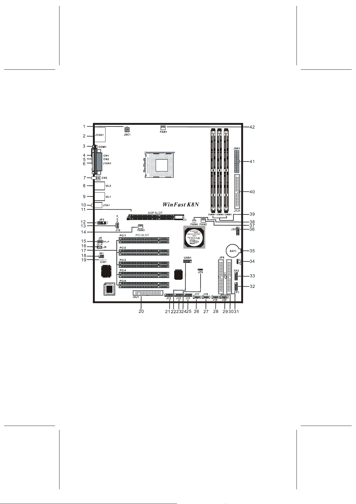
2.1. Jumper Position
1. J8C1 12. JP3 22.USB1 33. FP2
2. J12A1 13. J10 23. J12 34. J4J1
3. COM1 14. FAN3 24. JP9 35. BAT1
4. CN1 15. J8 25. J11 36. J22
5. CN2 16. J9 26. J17 37. FAN2
6. J10A1 17. PCI1-5 27. J18 38. FAN4
7. CN3
8. UL2
9. UL1
10. J7A1 20. J9J1 31. J7K1 42. FAN1
11. AGP 21. J13 32. FP1
4
18. IR1
19. CIR1
28. J19
29. J20
30. JP8
39. DIMM1-3
40. J7J1
41. J9K1
Page 9

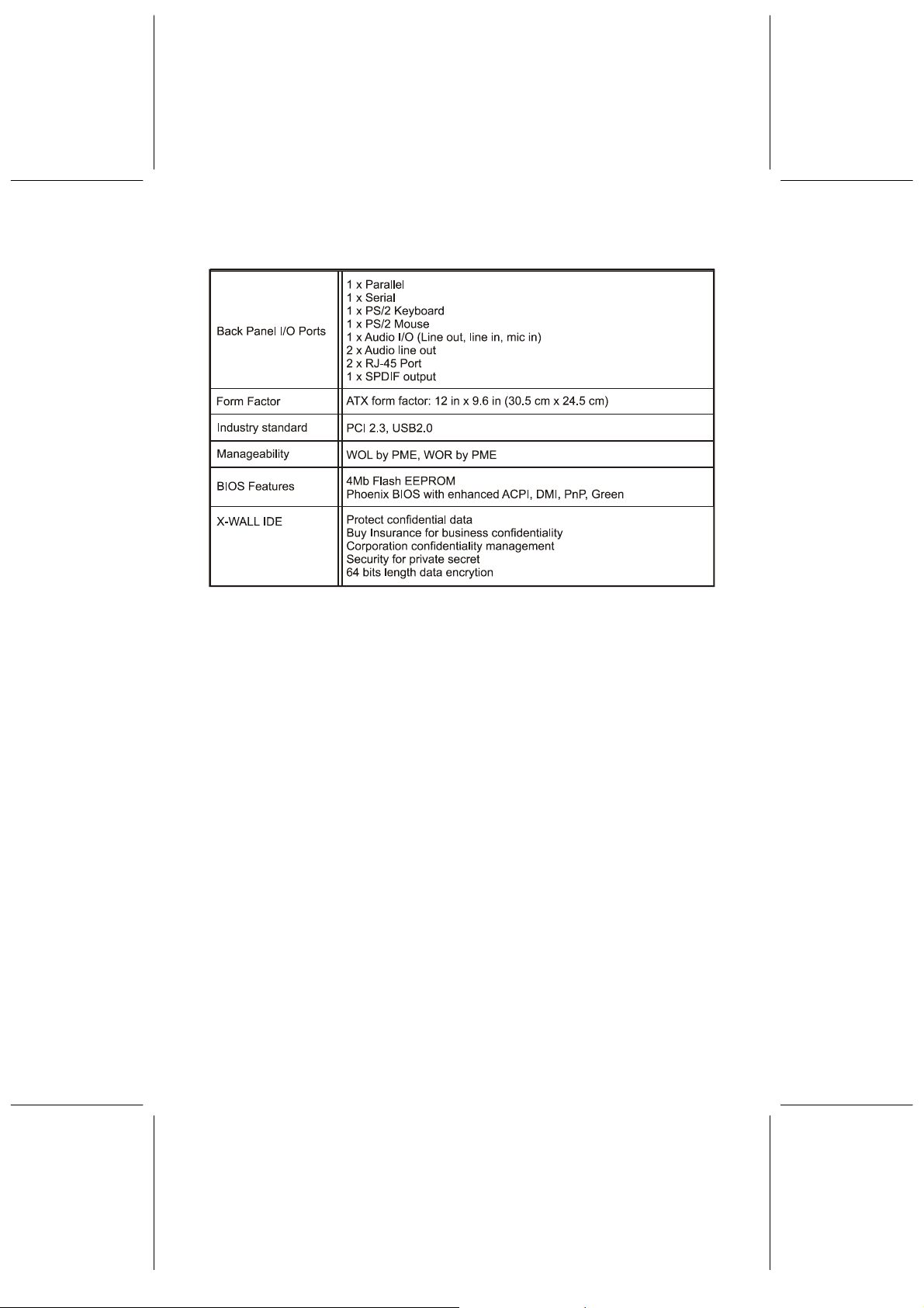
2.2. Jumper/Connector Listing
Jumper/Connector Description
1. J8C1 12V CPU vcore power connector
2. J12A1 PS2 keyboard and mouse ports
3. COM1 COM1 connector
4. CN1 Surround left and right
5. CN2 Center and bass
6. J10A1 Print port connector
7. CN3 SPDIF out connector
8. UL2 USB ports and 10/100 LAN connector
9. UL1 USB ports and 1000 LAN connector
10. J7A1 Mic in, Line in, Line out
11. AGP AGP slot
12. JP3 Audio front panel header
13. J10 AUX input connector
14. FAN3 System fan connector
15. J8 CD input connector
16. J9 CD input connector
17. PCI1-5 PCI slots
18. IR1 IR connector
19. CIR1 CIR connector
20. J9J1 Floppy disk connector
21. J13 IEEE1394 connectors
22. USB1 USB Connector
23. J12 IEEE1394 connectors
24. JP9 SATA selection
25. J11 IEEE1394 connectors
26. J17 SATA connectors
27. J18 SATA connectors
28. J19 SATA connectors
29. J20 SATA connectors
30. JP8 Hard disk connectors (X-Wall IDE)
31. J7K1 Hard disk connectors (Primary IDE)
32./33. FP1/FP2 Case Signal Connector: PWR SWITCH, RESET, KEY
LOCK, SPEAKER, IDE_LED, ACPILED
34. J4J1 Clear CMOS data
35. BAT1 Battery
36. J22 Secure key connector
37. FAN2 Chipset fan connector
5
Page 10

38. FAN4 Chipset fan connector
39. DIMM1-3 Memory module connectors
40. J7J1 Hard disk connectors (Secondary IDE)
41. J9K1 ATX power connector
42. FAN1 CPU fan connector
2.3. Jumper Settings
Clear CMOS Data
Jumper Setting
J4J1
Audio output selection
Jumper Setting
JP3
SATA Select
Jumper Setting
JP9
Clear CMOS
Normal (Default)
From back panel (Default)
From front panel
Enable (Default)
Disable
1
1
6
Page 11

3. Hardware Setup
Static Precautions
Static discharge can damage electronic components. To prevent that, it is
important to handle it carefully. The following measures will suffice your equipment
from static.
y Use a grounded wrist strap designed for static discharge.
y Touch a grounded metal object before you remove the board from the
anti-static bag.
y Handle the board by its edges only; do not touch its components, peripheral
chips, memory modules, or gold contacts. Do not touch pins on chips or
modules.
y Put the system board and peripherals back in anti-static bags when they are
not in use.
y For grounding purposes, be sure your computer chassis provides excellent
conductibility between its power supply, case, the mounting fasteners, and the
system board.
3.1. CPU Installation
Please refer to the instruction manual of the CPU for how to install the CPU.
NOTE: As the user select CPU fan, we suggest you to purchase CPU fan that
can guide the wind direction to Power MOS and RAM – this way can
increase the performance of the heat sink and the stability of the
motherboard.
7
Page 12

3.2. Memory Installation
The motherboard provides three 184-pin DIMM (Double In-Line Memory Module)
sockets, DIMM1, DIMM2, and DIMM3. Total memory is up to 2GB. K8N (Pro)
supports DDR200, DDR266, DDR333 and DDR400 memory.
NOTE: WinFast K8N (Pro) has special design for the users. The original setup
of AMD Athlon64 only provides 2 RAM DIMM slots, if you have 3
DIMM RAM module, please refer to the following steps to proceed
installing setup.
Step 1: IF you use 1 or 2 DIMM RAM module, please plug in DIMM1 slot and
DIMM2 slot. (purple)
Step 2: If you have 3 DIMM RAM module, please refer to the following list to install
it.
Unbuffered DIMM Support
8
Page 13
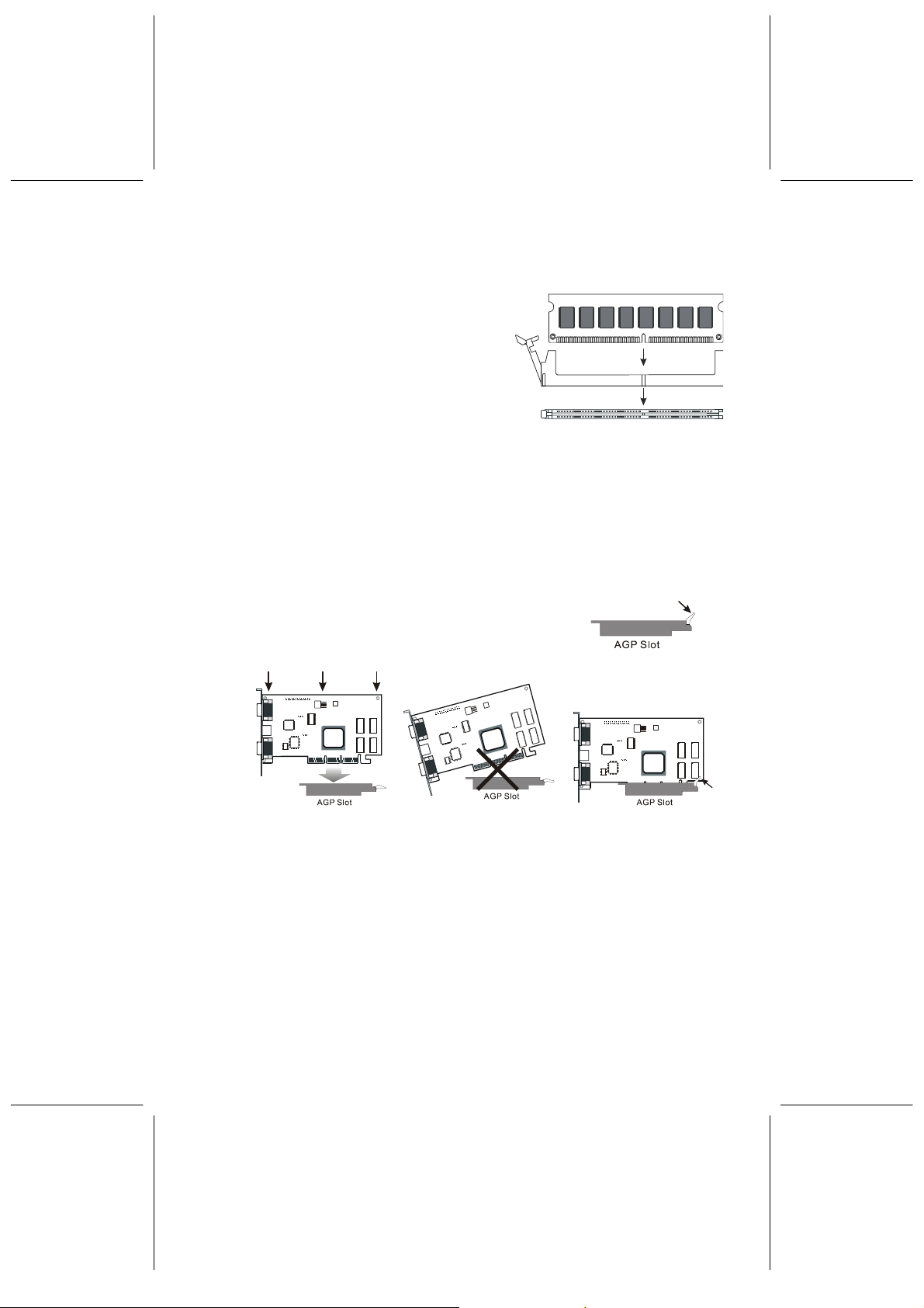
DIMM Installation Procedures
The DIMM slot has one key marked
“2.5V”, thus making the module only fit in
one direction. Note that the module must
be a 2.5 V unbuffered DIMM.
Step 1: Insert the module vertically into
the DIMM socket, and then
push it in.
Step 2: The plastic clip at the side of the DIMM socket will automatically close.
3.3. AGP Display Adapter Installation
The AGP slot on WinFast K8N supports only 1.5 V AGP device. To install an AGP
display adapter, follow these steps:
Step 1: Push the clip at the end of AGP slot.
Step 2: Position the AGP card over the AGP slot. Do
not tilt the card. Insert the bus connector in the
slot and gently press the bus connector down.
Step 3: Push the clip back to close it.
Step 1
Step 2
Step 3
9
Page 14
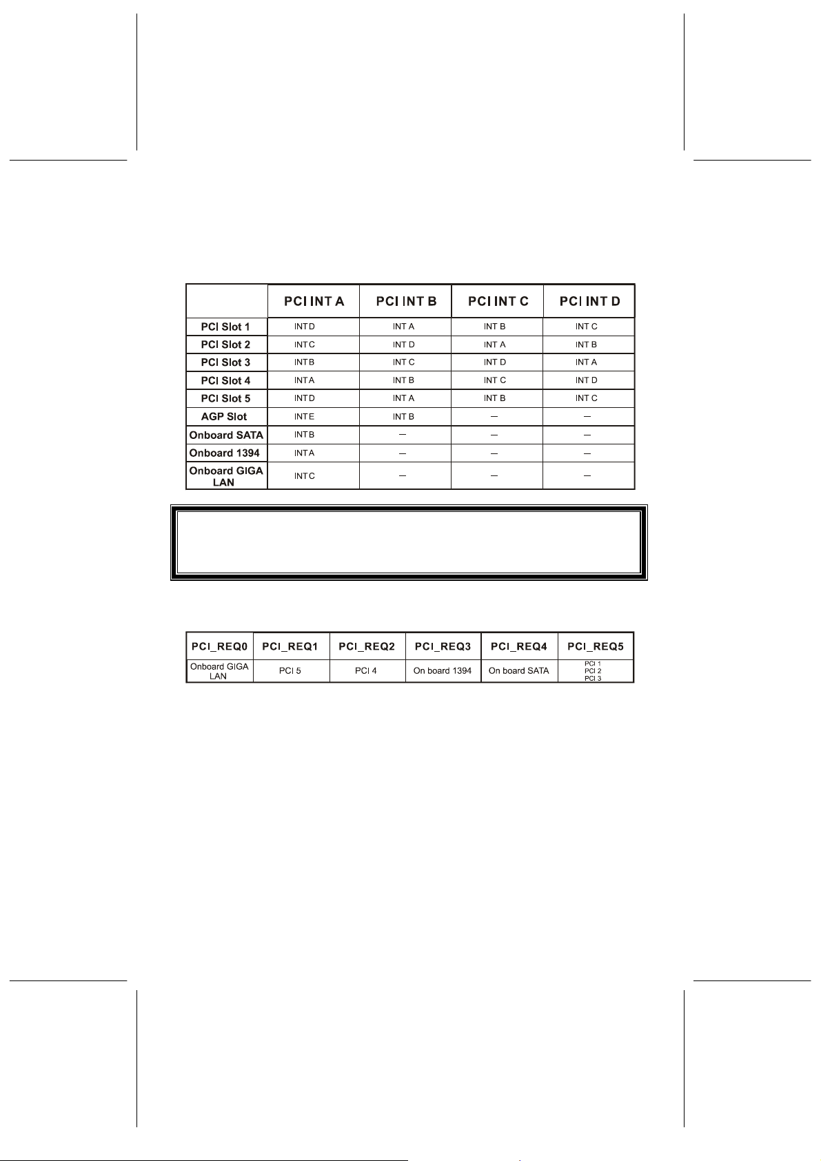
3.4. Configuring an Expansion Card
A. IRQ assignments for this motherboard
NOTE: When using PCI cards on shared slots, endure the driver support
“Share IRQ” or that the cards do not need IRQ assignments.
Otherwise, conflicts will arise between the two PCI groups, making
the system unstable and the card inoperable.
B. Request/Grant assignments for this motherboard
10
Page 15
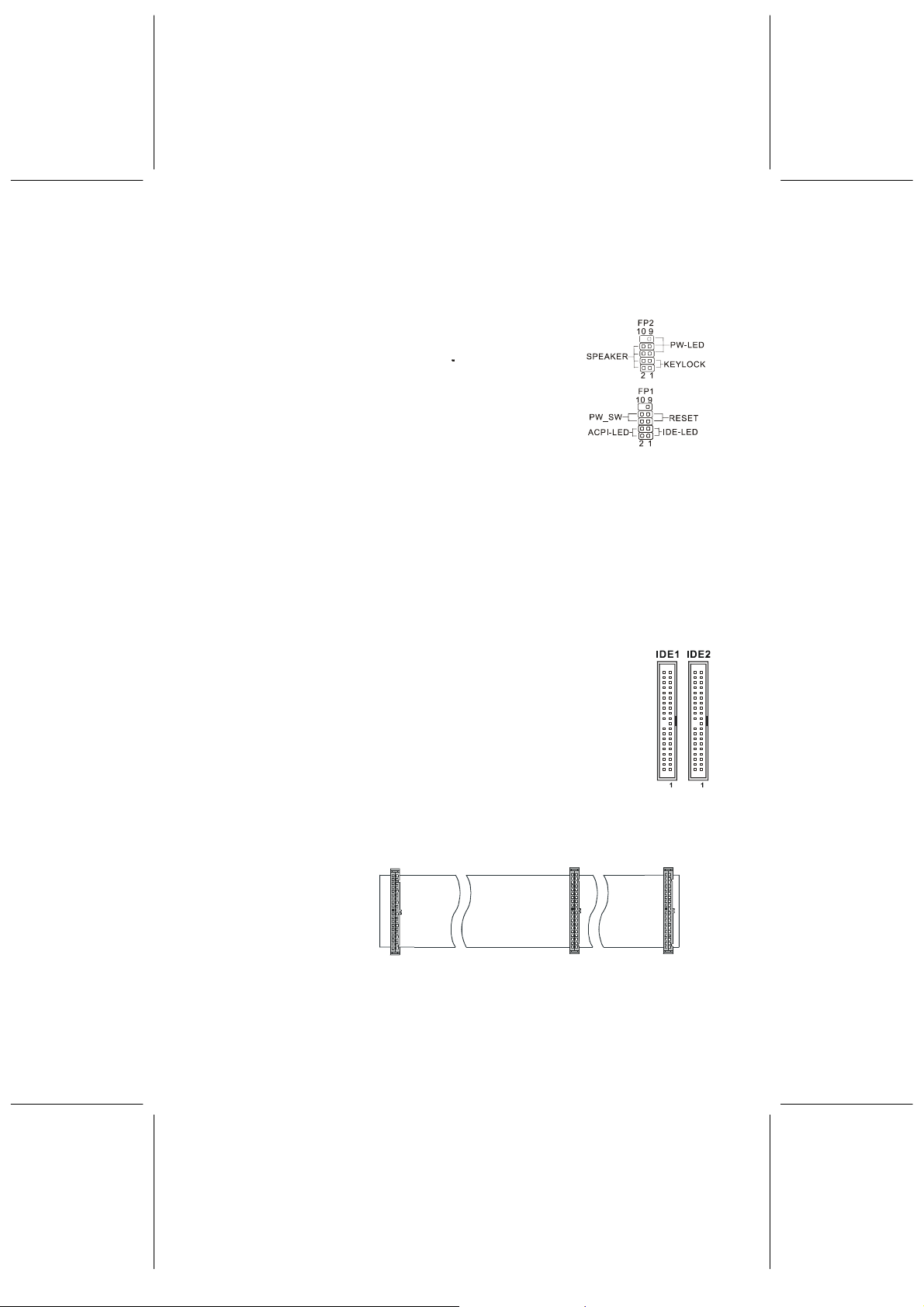
3.5. Connecting Instructions
How each connector is connected and what it does is described here in
detail. See Chapter 2 to locate connectors.
Case Signal Connectors (FP1 & FP2)
FP2:
Pins [1&3] KEYLOCK: Keyboard lock switch lead. It
connects to the case-mounted keylock switch, allowing
you to disable the keyboard function for security purpose.
Pins [5&7&9] PW-LED: Power LED. Always lit when
system power is on.
Pins [2&4&6&8] SPEAKER: Connects to the speaker on system’s case.
FP1:
Pins [1&3] IDE-LED: IDE hard disk LED shows the activity of a hard disk drive.
Pins [2&4] ACPI-LED: For ACPI LED connection on the case.
Pins [5&7] RESET: Connects to the reset button on the case. The reset button is
used to “cold-boot” the system without actually turning off the power, reducing
wear and tear on the power supply. Avoid rebooting the system when the HDD
LED is blinking.
Pins [6&8] PW_SW: Allows connecting to the power button on the case.
Hard Disk Connector
The on-board Enhanced IDE controller can support up to 4 IDE hard
drives or other ATAPI devices, such as CD-ROMs. This controller, as
with all Enhanced IDE controllers, consists of both Primary (IDE 1) and
Secondary (IDE 2) ports. Each port has an associated connector and
cable, which can support up to 2 ATAPI devices each.
All IDE devices have jumpers, which allow the user to configure the
device as either “Master” or “Slave”. A Master device is one that is
ALONE on the IDE cable, whereas a Slave device is installed as a
SECOND device on the same cable. Keep in mind that the Master device will
appear before the Slave device in the CMOS Setup, as well as the Operating
System software.
*Refer to the device
documentation for
Mainboard IDE Port
Slave Drive
Master Drive
jumper settings.
The Secondary
IDE port can be
used for up to 2
additional ATAPI
devices.
Blue
Connector
Gray
Connector
Black
Connector
Normally it’s recommended that you connect your first hard drive to the
Primary port, and the first CD-ROM to the Secondary.
11
Page 16

Make sure to align the RED stripe on the ribbon cable with Pin-1 on the
motherboard IDE connector. On most hard drives and CD-ROMs, the RED stripe
should be oriented towards the power connector of the device.
When using Ultra ATA 66/100 IDE cable (as shown above), the black color
connector on the cable is for Master drive, gray color is for Slave drive and blue
color is for connecting to IDE port onboard.
X-Wall IDE
The X-Wall IDE requires no device driver and is independent from and invisible to
all operating systems. As long as the driver is Ultra ATA 66/100/133 compliant,
X-Wall IDE will work in the system. Once authenticated, its operation is completely
transparent to all users who do not require managing usually seen complex
Graphical User’s Interface (GUI) of other solutions.
The X-Wall IDE comes with a pair of portable
device status and most importantly, the DES/TDES “Secret Key”. The X-Wall
Secure Key serves as an exclusive device for authentication from which the X-Wall
Secure Key must present itself to activate the X-Wall IDE.
The user can use X-WALL to proceed the data security. You can connect J22 to
any 6-pin 1394 connector, please refer to the following figure.
But if you connect J22 to the attached 1394 slot of the case, the 1394 cable of
WinFast K8N (Pro) can connect to J11/J12/J13, and then 1394 device can use it.
X-Wall Secure Keys that loads
12
Page 17
NOTE: 1. Does not support ATAPI devices such as CD-ROM, CD-R, CD-RW,
DVD-ROM or DVD-RW. 2. Please keep these two keys carefully. In
security enable condition, you will not read the hard disk data if you
miss the keys.
Floppy Disk Connector (J9J1)
The on-board floppy controller supports 2 floppy disk
drives. Make sure the RED stripe on the ribbon cable is
oriented towards Pin-1. Notice the “twist” between the sets of connectors on the
floppy cable. The floppy drive “A” position is at the END of the cable, whereas
floppy drive “B” is hooked to one of the connectors on the other side of the twist.
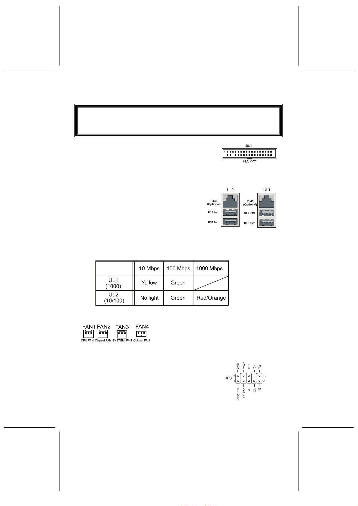
RJ45 Ethernet Connector and USB Connectors
(UL1, UL2)
RJ45 LAN connector and USB peripheral devices
connectors.
UL1 provides 1000 Mbps LAN.
UL2 provides 10/100 Mbps LAN.
WinFast K8N (Pro) supports 10/100/1000 Mbps LAN. When UL1 and UL2
transfer in different network, please refer to the represent meaning of the
light as below:
Cooling Fans (FAN1, FAN2, FAN3, FAN4)
CPU fan (FAN1), Chipset fan (FAN2), system fan
(FAN3) and Chipset fan (FAN4) are small 3-pin
Header Connectors that provide 12-Volt power for
CPU fan, power fan, and system fan. Plug in the fan
cable to the connector.
Audio Out Selection (JP3)
JP3 can let you select audio out from the front panel or
back panel. Please refer to Chapter 2.3 Jumper Settings
to set it.
13
Page 18

Stereo Audio/Video In Connectors (J8, J9, J10)
J8 and J9 allow you to receive stereo audio input from
internal CD ROM drives. J10 is for connecting other
auxiliary audio sources.
Power Supply Connector (J9K1)
This motherboard features an ATX-style Power Supply
Connector. This connector is keyed to prevent
connection in the wrong direction. Line up the locking
mechanism on the connector from the Power Supply
with the tab on the motherboard connector. Press down
until the two connectors are locked.
Serial, Parallel and Audio Ports (J10A1)
Includes one 25-pin D-Sub header, 9-pin
D-Sub header (COM1), and CN1 (Surround
Left/Right) /CN2 (Center/Bass) /CN3 (SPDIF
Out).
MIC, Line In, Line Out
Mic: Allows microphones to be connected for
inputting sound.
Line In: Allows tape players or other audio sources to be recorded by
your computer or played through the Line Out.
Line Out: Connected to headphones or speakers with amplifier.
WinFast K8N(Pro) supports 6 channel output, the user can connect line
out and CN1 (Surround Left/Right)/CN2 (Center/Bass) to enjoy the best
sound effect
* If CN1 and CN2 cannot output the voice, please don’t tick
“Rear Speakers connected to Line IN” and “Center
Speaker and subwoofer connected to Microphone” in
volume option of the controller.
IrDA-Compliant Infrared Module Connector (IR1, CIR1)
The IrDA connector brackets hook directly to these connectors on
the motherboard. These connectors provide support for the
optional wireless transmitting and receiving infrared module.
CIR1 connector is for CIR; IR1 connector is for IR.
PS/2 Keyboard and Mouse Connector (J12A1)
These two connectors are located on the back panel of the
motherboard.
14
Page 19

USB Connectors (USB1) (optional)
Each of these connectors is for connecting an optional USB module to provide
two additional USB connectors.
NOTE: Never
connect one USB1 cable to 1394 connector that will damage
the motherboard.
1394 Connectors (J11/J12/J13)
WinFast K8N offers 3 1394 connectors (J11/J12/J13). You can use the attached
1394 module and connect it to 1394 module of the case.
WinFast K8N
15
Page 20

WinFast K8N Pro
NOTE: Never connect a 1394 cable to USB1 connector that will damage the
motherboard.
SATA Connectors (J17/J18/J19/J20)
WinFast K8N(Pro) offers 4 SATA connectors that can support SATA RAID0,
RAID1 and RAID0+1. Please refer to the following figure about the connecting
way:
16
Page 21

4. BIOS Setup
To enter the Award BIOS program's main menu:
Turn on or reboot the system.
After the diagnostic checks, press the [Del] to enter the Award BIOS Setup Utility.
To select items:
Use the arrow keys to move between items and select fields.
From the Main Menu, press arrow keys to enter the selected submenu.
To modify selected items:
Use the [Up]/[Down] keys to modify values within the selected fields. Some fields
let you enter values directly.
4.1. Main Menu
NOTE: If users find that there is any different from your installing screen
while installing the driver, please follow the steps in actual situation
to operate.
Once you enter the AwardBIOS CMOS Setup Utility, the Main Menu appears on
the screen. Main Menu presents you the Setup functions included two exit choices.
You could use the arrow keys to select among the items and then press Enter to
the submenu.
* Description of selected item is shown in the column on the bottom of the screen.
17
Page 22

4.2. Standard CMOS Features
The Standard CMOS Features allows you to choose the options in the setting item
for basic system configuration.
* The Item Help column contains the description of selected item.
Date [mm:dd:yy]
The BIOS determines the day of the week from other date information. It is for
information only.
Time [hh:mm:ss]
The time format is <hour> <minute> <second>. The time is calculated based on the
24-hour military-time clock. For example, 1 p.m. is 13:00:00.
IDE Primary Master/Primary Slave/Secondary Master/Secondary Slave
After pressing [Enter], a menu window appears as shown on below:
The BIOS supports up to four IDE drives. This section does not show information
about other IDE devices, such as a CD-ROM and SCSI drives.
18
Page 23

* The Item Help column contains the description of selected item.
IDE HDD Auto-Detection
The “IDE HDD Auto-Detection” utility is a very useful tool especially when you do
not know the type of hard disk you are using. You can use this utility to detect the
correct disk type installed in the system automatically. The BIOS will automatically
detect the hard disk size and model during POST.
The Award BIOS supports 3
HDD modes: NORMAL, LBA and LARGE modes. The
Generic access mode, neither BIOS nor IDE controller, will make transformations
during accessing.
NOTE: There must be some software involved to support LBA or LARGE
mode of HDDs. All the software needed is located in the Award
HDD Service Routine (INT 13h). It may fail to access a HDD with
LBA (LARGE) mode selected if you are running under an Operating
System, which replaces the whole INT 13h. UNIX operating system
do not support either LBA or LARGE, and must utilize the Standard
mode. UNIX can support drives larger than 528MB.
Under the AUTO Mode, the BIOS can automatically detect the specifications and
optimal operating mode of almost all IDE drives. When you select type Auto for a
hard drive, the BIOS detects its specifications during POST, every time the system
boots.
IT IS RECOMMENDED THAT YOU SELECT THE TYPE AUTO FOR ALL DRIVES.
19
Page 24

Drive A /Drive B [1.44M, 3.5 in.]
Select the correct specifications for the diskette drive(s) installed on your system.
Video [EGA/VGA]
Select the type of primary video subsystem on your system. The BIOS usually
detects the correct video type automatically, and supports a secondary video
subsystem that cannot be selected in Setup.
Halt On [All, But Keyboard]
During the power-on self test (POST), the system stops if the BIOS detects a
hardware error. You can ask the BIOS to ignore certain errors and continue the
process. There are the options:
All Errors: If the BIOS detects any non-fatal error, POST stops and
prompts you to take corrective action.
No Errors: POST does not stop for any error.
All, But Keyboard: POST does not stop for keyboard error, but stops for all
other errors.
All, But Diskette: POST does not stop for diskette drive errors, but stops for all
other errors.
All, But Disk/Key: POST does not stop for a keyboard or disk error, but stops for
all other errors.
Memory
You can not change the value in the Memory fields which are information only. The
setting item shows the total installed random access memory (RAM) and amounts
allocated to base memory, extended memory, and other (high) memory.
RAM is the computer’s working memory where the computer stores programs and
data currently being used, so they are accessible to CPU.
Base Memory: Typically 640 KB is also called conventional memory. The
DOS operating system and conventional applications use this
area.
Extended Memory: The memory is over the 1MB boundary.
Total Memory: Total memory available from the system.
20
Page 25

4.3. Advanced BIOS Features
* The Item Help column contains the description of selected item.
Virus Warning [Disabled]
The BIOS will halt on the system. Then the warning message appears as follows if
there is virus.
!PBVA WARNING!
Paragon Boot Virus analyzer has
detected virus activity on hard disk
We recommend you to press:
[Enter] Boot from clean disk
[C] Continue Boot
NOTE: When this item is enabled, the monitoring boot sector virus only
happens at the booting period. After you enter the system, this
function is disabled automatically. So you can run any kind of
program, such as many disk diagnostic programs, which attempt to
access boot sectors or the partition table of hard disk drive when it
is running.
CPU Internal/External Cache
Cache memory is additional memory that is much faster than conventional DRAM
(system memory). When the CPU requests data, the system transfers the
requested data from the main DRAM into cache memory, for even faster access by
the CPU. Select Enabled to enable cache.
21
Page 26

External Cache [Enabled]
The options are: Enabled and Disabled.
Quick Power On Self Test [Enabled]
Select Enabled to reduce the amount of time required to run the POST. A quick
POST skips certain steps. We recommend that you normally disable quick POST.
Better to find a problem during POST than lose data during your work.
First, Second, Third, Fourth Boot Device [HDD-0, Floppy, SCSI, Disabled]
Thiese setup fields determine which drive to be searched first, second or third for
the disk operating system (i.e. DOS). You can select your priority bootup drives as
Floppy drive A, IDE Hard Disk Drive C, D, E, F, or SCSI.
Swap Floppy Drive [Disabled]
This field is effective only in system with two floppy drives. This item allows you to
determine whether to enable the swap floppy drive or not (i.e. physical floppy disk
A assigned to logical drive B or physical drive B to logical drive A).
Boot Up Floppy Seek [Enabled]
During the “POST” process, BIOS will determine if the floppy disk drive installed is
40 or 80 tracks. 360K-type is 40 tracks while 760K, 1.2M and 1.44M are all 80
tracks. Because few modern PCs have 40-track floppy drives, we recommend that
you set this field to Disabled to save time.
Boot Up NumLock Status [On]
This field allows you to determine the default state of the numeric keypad. “On”:
keypad is number keys after boot up. “Off”: keypad is arrow keys after boot up.
Gate A20 Option [Fast]
Gate A20 refers to the way the system addresses memory above 1MB (extended
memory). When set to Fast, the system chipset controls Gate A20. When set to
Normal, a pin in the keyboard controller controls Gate A20. Setting to Fast
improves system speed, particularly with OS/2 and Windows.
Typematic Rate Setting [Enabled]
Setting Enabled allows you to adjust both settings. You can use this feature to
accelerate cursor movement with the arrow keys. When this item is set Disabled,
keep holding down a key will let the system to use the default typematic rate delay
of 250 msec, and typematic rate of 6 chars/sec to input repeatedly.
Typematic Rate (Chars/Sec) [6]
When “Typematic Rate Setting” is Enabled, its selections allow you to select the
rate at which character repeats when you hold down a key.
Typematic Delay (Msec) [250]
When “Typematic Rate Setting” is Enabled, its selections allow you to select the
22
Page 27

delay before key strokes begin to repeat.
Security Option [Setup]
If you have set a password at USER PASSWORD option in main menu, select
whether the password is required every time the System boots, or only when you
enter Setup. The options include: System and Setup.
APIC Mode [Enabled]
The options are: Enabled and Disabled.
MPS Version Control For OS [1.4]
The options are: 1.1 & 1.4.
OS Select For DRAM > 64MB [Non-OS2]
Allow you to access memory that is over 64MB in OS/2. Choose OS2 when you
are using OS2 and SDRAM size greater than 64 MB. Choose Non-OS2 for other
operating systems. The options are: Non-OS2, OS2.
HDD S.M.A.R.T. Capability [Disabled]
The options are: Enabled and Disabled.
Small Logo (EPA) Show [Enabled]
The options are: Enabled and Disabled.
4.4. Advanced Chipset Features
* The Item Help column contains the description of selected item.
This section allows you to configure the system based on the specific features of
the installed chipset. This chipset manages bus speeds and access to system
memory resources, such as DRAM and the external cache. It also coordinates
23
Page 28

communications between the conventional ISA bus and the PCI bus. It must be
stated that these items should never need to be altered.
The default settings have been chosen because they provide the best operating
conditions for your system. The only time you might consider making any changes
would be if you discovered that data was being lost while using your system.
DRAM Configuration [Press Enter]
DDR Timing Setting by [Auto] & [Manual].
[Manual]: Max Memclock (MHz)-100/133/166/200.
CPU Overclock in MHz [200]
The options are: 200~ 300.
AGP Overclock in MHz [66]
The options are: 66~ 100.
AGP Aperture size (MB) [64M]
The options are: 32M, 64M, 128M, 256M, and 512M.
AGP 3.0 Speed [Auto]
The options are: Auto, 4x, and 4x8x
AGP Fast Write [Auto]
The options are: Auto & Disable.
AGP Sideband Address [Auto]
The options are: Auto & Disable.
Clock Spread Spectrum [Disable]
The options are: Enable and Disable.
CPU Thermal-Throttling [50.0%]
The options are: Disable, 12.5%, 25.0%, 37.5%, 50.0%, 62.5%, 75.0%, and
87.5%.
LDT Downstream Width [8bits]
The options are: Auto & 8bits.
LDT Speed [3x]
The options are: 1x, 2x, 2.5x, 3x, and 4x.
Special I/O for PCI Card [Disable]
The options are: Enable and Disable.
24
Page 29

System BIOS Cacheable [Disable]
The options are: Enable and Disable.
4.5. Integrated Peripherals
This Menu Setup allows you to configure your IDE, USB keyboard, Floppy Drive,
Parallel Port, Serial Port, and IR function.
* The Item Help column contains the description of selected item.
On-Chip IDE Channel0 [Enabled]
Selecting Enabled allows you to adjust the functions of Primary PIO and UDMA.
On-Chip IDE Channel1 [Enabled]
Selecting Enabled allows you to adjust the functions of Secondary PIO and UDMA.
Primary Master/Slave PIO, Secondary Master/Slave PIO [Auto]
The four IDE PIO (Programmed Input/Output) fields let you set a PIO mode (0-4)
for each of the four IDE devices that the onboard IDE interface supports. Modes 0
through 4 provide successively increased performance. In Auto mode, the system
automatically determines the best mode for each device. The options are: Auto,
Mode 0, Mode 1, Mode 2, Mode 3, and Mode 4.
Primary Master/Slave UDMA, Secondary Master/Slave UDMA [Auto]
Ultra ATA 66/100 implementation is possible only if your IDE hard drive supports it
and the operating environment includes a DMA driver (Windows 95 OSR2 or a
third-party IDE bus master driver). If your hard drive and your system software both
support Ultra ATA 66/100, select Auto to enable BIOS support. The options are:
Auto and Disabled.
25
Page 30

IDE Prefetch Mode [Enabled]
The options are: Enabled and Disabled.
Init Display First [PCI Slot]
If you install an additional PCI display cards, you can select either a PCI display
card or the onboard/AGP display to activate the display boot-up screen.
OnChip USB [V1.1+V2.0]
Selecting Enabled allows the system Universal Serial Bus (USB) controller when
you have USB peripherals. The options are Disabled, V1.1, and V2.0.
USB Mouse Support [Enabled]
If you use a USB keyboard, please choose USB A or USB B.
USB Keyboard Support [Disabled]
The options are: Enabled and Disabled.
Primary AudioCodec at [Onboard]
The options are: Onboard, and AMR/CNR.
X-Wall IDE Chip Set [Enabled]
The options are: Enabled and Disabled.
X-Wall Function [Bypass]
The options are: Bypass and En/Decrypt.
AC97 Audio [Auto]
Selecting Auto allows the BIOS to detect the audio device you use.
MC97 Modem [Auto]
The options are: Auto and Disabled.
MAC Lan (nVIDIA) [Auto]
The options are: Auto and Disabled.
IDE HDD Block Mode [Enabled]
Selecting Enabled allows automatic detection of the optimal number of block
read/writes per sector the drive can support.
Power ON Function [BUTTON ONLY]
Allows you to choose a way to power on. The options include Password, Hot KEY,
Mouse Left, Mouse right, Any KEY, BUTTON-ONLY, and Keyboard 98.
KB Power ON Password [Enter]
This setting item allows you to set a password for keyboard powering on.
26
Page 31

Hot Key Power ON [Ctrl-F1]
Allows you to choose one of the hot keys to power on from F1 to F12.
Onboard FDC Controller [Enabled]
This setting item allows you to enable or disable the onboard FDC controller.
Onboard Serial Port 1/Port 2
Select an address and corresponding interrupt for the 1st and 2nd serial ports. The
choices: 3F8/IRQ4, 2F8/IRQ3, 3E8/IRQ4, 2E8/IRQ3, Disabled, and Auto.
UART Mode Select
Select an infrared port mode. The options are: Normal, IrDA, and ASKIR.
RxD, TxD Active [Hi, Lo]
The options are: Hi,Hi, Hi,Lo, Lo,Hi, and Lo,Lo.
IR Transmission Delay
The options are: Enabled and Disabled.
UR2 Duplex Mode [Half]
This item selects the IR function when the choice of the UART mode is ASKIR. The
options are: Full and Half.
Use IR Pins [IR-Rx2Tx2]
The options are: RxD2,TxD2 and IR-Rx2Tx2.
Onboard Parallel Port [378/IRQ7]
This item allows you to determine access onboard parallel port controller with
which I/O address. The options are: 378/IRQ7, 278/IRQ5, 3BC/IRQ7, and
Disabled.
Parallel Port Mode [SPP]
Select an operating mode for the onboard parallel port. Normal EPP (Extended
Parallel Port) ECP (Extended Capabilities Port) ECP+EPP PC AT parallel port
Bi-directional port Fast, buffered port Fast, buffered, bi-directional port.
Set to Normal unless you are certain your hardware and software both support
EPP or ECP mode. The options are: SPP, EPP, ECP, ECP+EPP and Normal.
EPP Mode Select [EPP1.7]
The options are: EPP 1.7 and EPP 1.9
ECP Mode Use DMA [3]
This field allows you to select a DMA channel for the port.
The options are: 1 and 3.
27
Page 32

PWRON After PWR-Fail [Off]
g
The options are: Off, On, and Former-Sts.
4.6. Power Management Setup
* The Item Help column contains the description of selected item.
ACPI Function [Enabled]
Selecting Enabled allows this function if you use ACPI compliant OS, such as
Windows 98 or Windows 2000.
ACPI Suspend Type [S1(POS)]
Three options are available: S1 (POS) and S3 (STR); and S1&S3. POS stands for
Power On Suspend. STR stands for Suspend To RAM.
Power Management [User Define]
This category allows you to select the type (or degree) of power saving and is
directly related to the following modes:
There are 4 selections for Power Management, three of which have fixed mode
settings.
Disable (default)
User Defined
Min. Power Savin
No power management. Disables all four modes
Allows you to set each mode individually. When not disabled,
each of the ranges are from 1 min. to 1 hr. except for HDD
Power Down which ranges from 1 min. to 15 min. and disable.
Minimum power management. Doze Mode = 1 hr. Standby
Mode = 1 hr., Suspend Mode = 1 hr., and HDD Power Down =
15 min.
28
Page 33

Max. Power
Saving
Only Power Management field on the Power Management Setup menu is set to
User Defined will the following fields be user configurable.
Video Off Method [DPMS Support]
This determines the manner in which the monitor is blanked:
Blank Screen: This option only writes blanks to the video buffer.
V/H SYNC+Blank: This selection will cause the system to turn off the vertical and
DPMS Supported: Select this option if your monitor supports the Display Power
HDD Power Down [Disabled]
This setting item will be able to change when Power Management is set to User
Define.
The options are: Enabled and disabled.
HDD Down In Suspend [Disabled]
The options are: Enabled and disabled.
Soft-Off by PBTN [Instant-Off]
This item allows you to set the off function of power button by software control.
The options are: Instant-off and Delay 4 sec.
Maximum power management -- ONLY AVAILABLE FOR SL
CPU’S. Doze Mode = 1 min., Standby Mode = 1 min.,
Suspend Mode = 1 min., and HDD Power Down = 1 min.
horizontal synchronization ports and write blanks to the video
buffer.
Management Signaling (DPMS) standard of the Video
Electronics Standards.
PowerOn After Pwr-Fail [Off]
The options are: Off, On, and Former-STs.
WOL( PME# ) From Soft-off [Disabled]
The options are: Enabled and disabled.
WOR( RI# ) From Soft-off [Disabled]
The options are: Enabled and disabled.
Power-On by Alarm [Disabled]
The options are: Enabled and disabled.
Day of Month Alarm [0]
Set a day for the alarm in month.
Time (hh:mm:ss) of Alarm [0 0 0]
Set a time for the alarm in hours, minutes, and seconds.
29
Page 34

4.7. PnP/PCI Configurations
* The Item Help column contains the description of selected item.
The PCI Personal Component Interconnect Bus was developed primarily to
address two important issues: (a) How to allow peripheral devices to take the fullest
advantage of the power of CPU technology, and (b) Provide a simpler installation
process for peripheral devices, such as Network cards, EIDE or SCSI controllers.
PCI accomplishes these goals with its 32-bit Data path Local Bus design, and
support for Plug&Play. Unlike older expansion bus architectures, PCI provides
peripherals with a direct connection to the CPU and memory. The PCI bus runs at
33Mhz and has a maximum transfer capability of 132MBps. With Plug & Play, the
system BIOS automatically determines hardware resources for new peripherals,
simplifying installation of multiple interface cards.
This Setup Menu provides configuration options for the PCI Bus and its assigned
resources.
Reset Configuration Data [Disabled]
Disabled: Normal Setting
Enabled: Select Enabled to reset Extended System Configuration Data
(ESCD) when you exit Setup if you have installed a new
add-on and the system reconfiguration has caused such a
serious conflict that the operating system cannot boot.
Resource Controlled By [Auto (ESCD)]
Manual: The field defines that the PNP Card's resource is controlled by
manual. You can setup whether IRQ-X or DMA-X is assigned
to PCI/ISA PnP or Legacy ISA Cards.
30
Page 35

Auto: If your ISA card and PCI card are all PNP cards. Set this field
to "Auto". The BIOS will assign the interrupt resource
automatically.
IRQ Resources [Press Enter]
Pressing Enter will take you to the IRQ Resources setup screen that allows you to
assign each IRQ to a device. When the resources are controlled manually,
pressing Enter will take you to the IRQ Resources setup screen that allows you to
assign each system interrupt as a PCI device or reserve the IRQ, depending on the
type of device using the interrupt:
PCI/VGA Palette Snoop [Disabled]
Selecting Enabled allows the BIOS to preview VGA Status, and to modify the
information delivered from the feature connector of the VGA card to the MPEG
card.
4.8. PC Health Status (O.T.S.)
* The Item Help column contains the description of selected item.
This section helps you to get more information about your system including CPU
temperature, FAN speed and voltages. It is recommended that you contact with
your motherboard supplier to get proper value about your setting of the CPU
temperature.
31
Page 36

4.9. X-BIOS II (Over-Clocking)
* The Item Help column contains the description of selected item.
AGP Slot Vddq Select [Default]
The options are: 1.8 V, 1.7 V, and 1.6V.
Memory Vmem Select [Default]
The options are: 2.80 V, 2.70V, Default and 2.50V.
Chipset Vcore Select [Default]
The options are: 1.90 V, 1.80 V, 1.70V and Default.
CPU Vcore Select [Default]
For setting the Vcore voltage. The options include: 0.800V ->1.700V and Default.
4.10. Load Basic Defaults
The BASIC Defaults have been set to provide the minimum requirements for your
system to operate. Its performance is lower than the “Load Best Defaults”. We
suggest you use “Load Best Default”. If your system card has compatibility issues,
use the “Load Basic Defaults”.
4.11. Load Best Defaults
The “Load Best Defaults” function loads the system manufacture default data. This
is the default setting from Leadtek. This function will be necessary when the system
CMOS data is corrupted or you forget your settings.
32
Page 37

4.12. Set Supervisor/User Password
Passwords can be set to provide protection for the BIOS configuration options, or
to restrict access to the computer itself.
When enabled, User Password will require all users to enter a password in order to
use the system, and/or enter the BIOS setup (but can’t change its contents). A
Supervisor Password is used to protect the stored CMOS options from being
changed by unauthorized users.
Keep in mind that when set, a password is required only when booting the system.
It will not provide protection to a system that is already booted.
The password check option is set in BIOS FEATURES SETUP by choosing either
System (the password prompt appears every time the system is powered on) or
Setup (the password prompt appears only when the user enters the BIOS Setup).
The password is stored in CMOS RAM, and can be cleared by removing the
battery for a while and then re-installing it back.
To set a password:
y You must first set the Supervisor password by choosing Supervisor Password
and pressing [ENTER]. Setup prompts for a password.
y Enter a 1~8 character password using letters, numbers, or a combination of
both. The specific characters are not shown as you enter them. Press
[ENTER].
y A confirmation box appears asking you to re-enter the password. Enter the
password again. Press [ENTER]. Follow the same procedure to set the User
Password.
To change a password:
y Select the appropriate password option (Supervisor or User) from the main
menu and press [ENTER]. Enter the current password and press [Enter]. The
screen does not display the characters entered. Enter in the new password,
then the confirmation. You cannot change the current password unless you
know it.
To erase a password:
y If you know the current password, but want to disable password checking,
follow the procedure for changing the password. When the Setup prompts for
the new password, simply press [ENTER]. You will see a message indicating
that the password is disabled.
y If you do not know the current password, you can clear the CMOS data by
removing the battery for a while and then re-installing it back (this will clear all
the user-defined BIOS).
33
Page 38

4.13. Save & Exit Setup
The “SAVE & EXIT SETUP” option will bring you back to boot up procedure with all
the changes you just recorded in the CMOS RAM
.
4.14. Exit Without Saving
The “EXIT WITHOUT SAVING” option will bring you back to normal boot up
procedure without saving any data into CMOS RAM, and will not destroy all the old
data in CMOS.
34
Page 39

5. Driver Installation
5.1. Under Windows 2000/XP
The installations of the chipset driver, GIGA LAN driver, SATA driver under
Windows XP/2000 all together take just one click. Follow the steps given below to
install all those drivers at once.
NOTE:The following instructions are for your reference only. If users find
that there is any different from your installing screen while installing
the driver, please follow the steps in actual situation to operate.
5.1.1. Installing Chipset Driver
Step 1: Insert the “WinFast K8N
Driver CD” into the CD-ROM
drive.
Step 2: Your computer will run the
Autorun program
automatically and the
WinFast K8N setup screen
will appear as shown in the
figure to the right. Click
‘Chipset Driver Setup’.
Step 3: The InstallShield Wizard
dialoge box appears ( see the
first figure to the right). It will
guide you through the
installation process. Click on
‘Next’.
35
Page 40

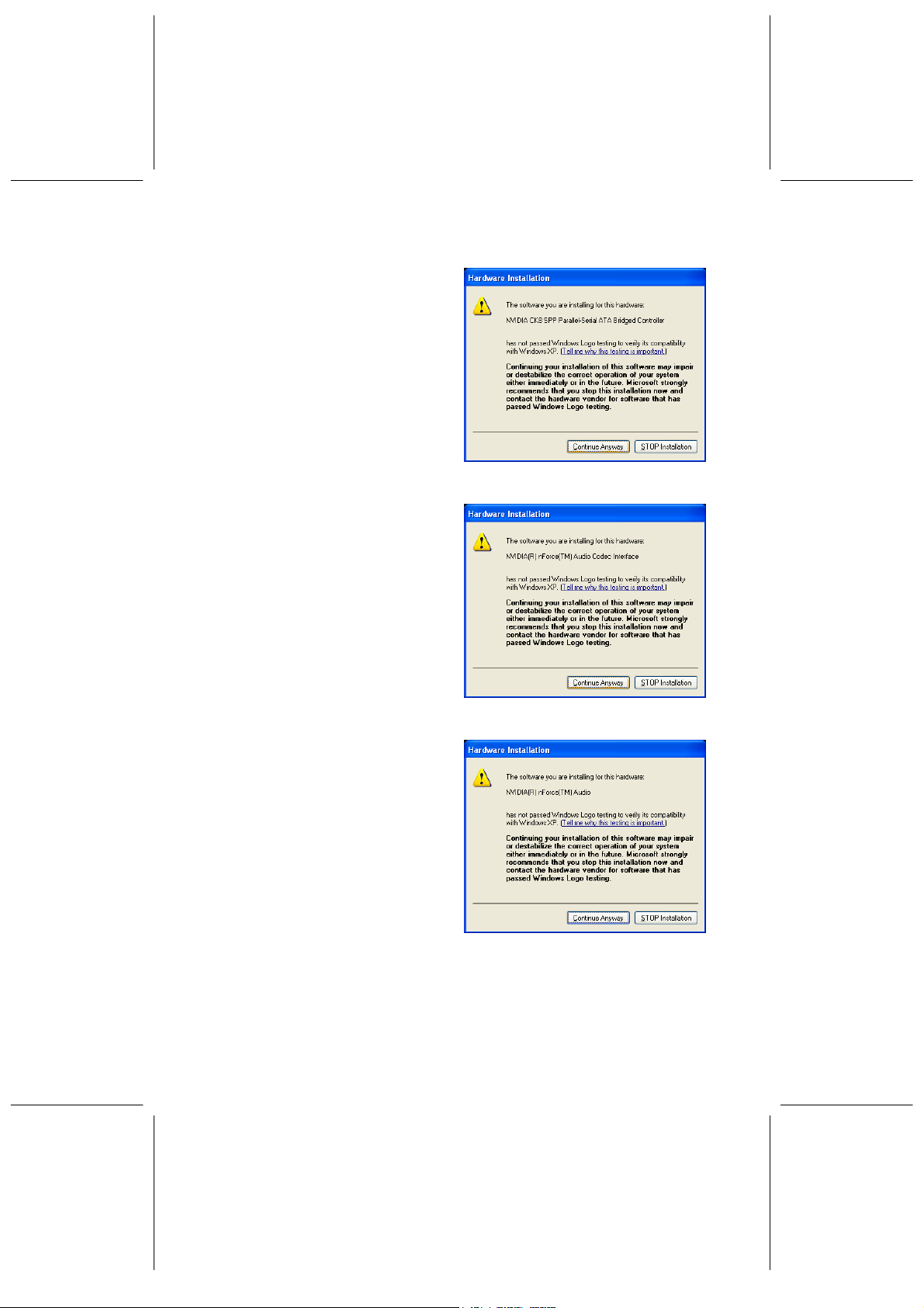
Step 4: The other warning dialogue
box about hardware
installation pops up. Please
ignore it and click on
‘Continue Anyway’ button.
Step 5: After read the information of
NVIDIA IDE SW Driver,
click ’Next’ to continue the
installing process.
Step 6: Another dialogue appears
and ask you to install NVIDIA
IDE SW driver, click ‘Yes’.
36
Page 41

Step 7: The other warning dialogue
box about hardware
installation pops up. Please
ignore it and click on
‘Continue Anyway’ button.
Step 8: The other warning dialogue
box about hardware
installation pops up. Please
ignore it and click on
‘Continue Anyway’ button.
Step 9: The other warning dialogue
box about hardware
installation pops up. Please
ignore it and click on
‘Continue Anyway’ button.
37
Page 42
Step 10: The other warning dialogue
box about hardware
installation pops up. Please
ignore it and click on
‘Continue Anyway’ button.
Step 11: The other warning dialogue
box about hardware
installation pops up. Please
ignore it and click on
‘Continue Anyway’ button.
Step 12: The other warning dialogue
box about hardware
installation pops up. Please
ignore it and click on
‘Continue Anyway’ button.
38
Page 43

Step 13: The system is now
completing chipset driver
installation. Please tick ”Yes,
I want to restart my computer
now” and click ‘Finish’.
5.1.2. Installing GIGA LAN Driver
Step 1: Firstly, click the icon “Start”
on the down-left corner of the
screen, then select “Setup”,
“Control Panel”, and
“System”. Then the dialogue
box ‘System Properties’ pops
up. Select “Hardware” this tab
and the scrren will shown in
the figure to the right. Then
click on ‘Device Manager’
button.
Step 2: In “Device Manager” screen,
please select “ Ethernet
Controller” in ‘other devices’.
39
Page 44

Step 3: In “Ethernet Controller
Properties” this screen, select
“General” this tab and click
‘Reinstall Driver’ to the next
step.
Step 4: The ‘Hardware Update
Wizard’ dialog box pops up
that says ‘The wizard helps
you install software for:
Ethernet Controller. Tick
‘Install from a list or specific
location (Advanced)’. Then
click ‘Next’.
Step 5: Select “Search for the best
driver in these locations”,
then tick “Include this location
in the search”. Click ‘Next’.
40
Page 45
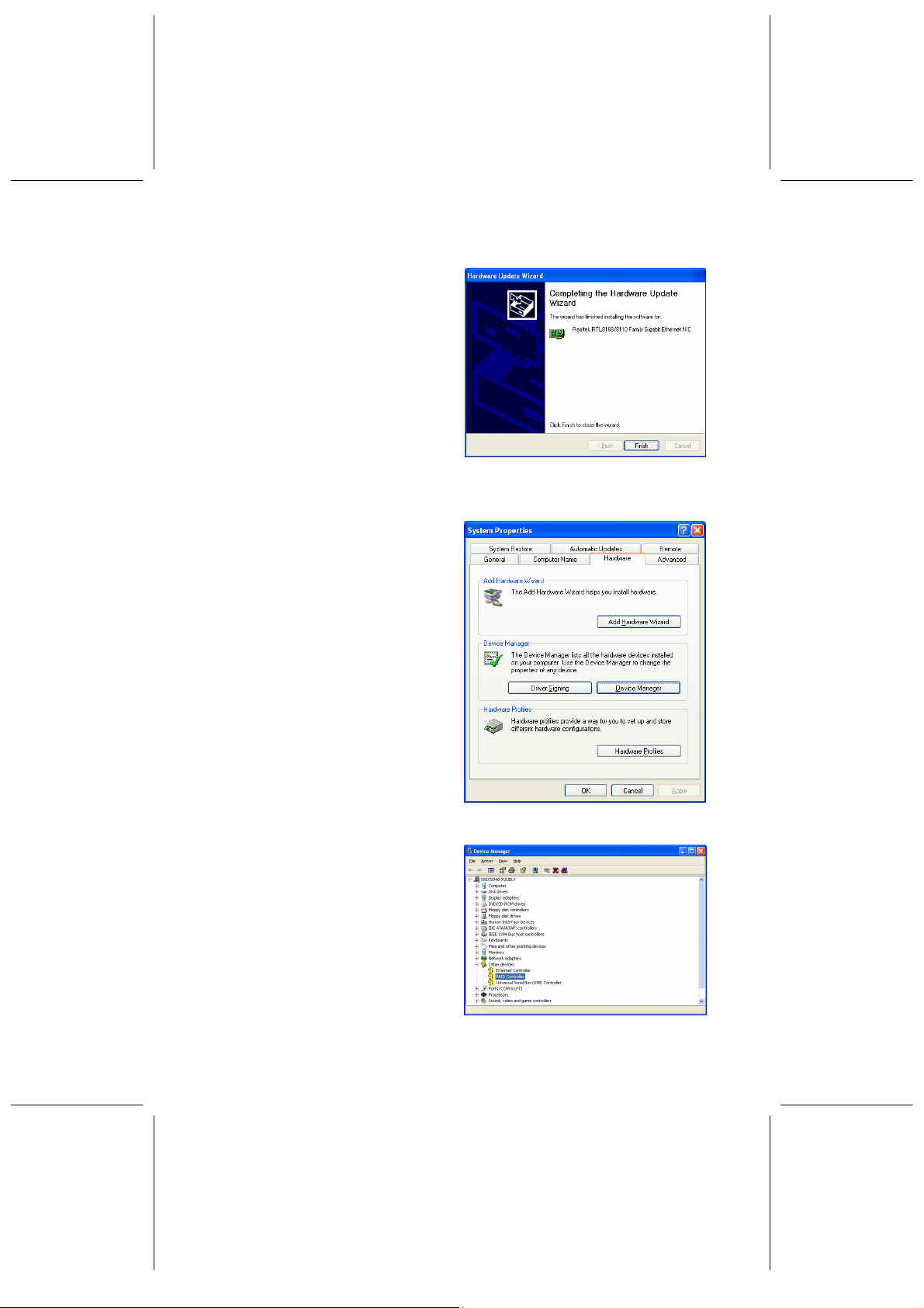
Step 6: The system is now
completing Giga Lan driver
installation. Click ‘Finish’.
5.1.3. Installing SATA Driver
Step 1: Firstly, click the icon “Start”
on the down-left corner of the
screen, then select “Setup”,
“Control Panel”, and
“System”. Then the dialogue
box ‘System Properties’ pops
up. Select “Hardware” this tab
and the scrren will shown in
the figure to the right. Then
click on ‘Device Manager’
button.
Step 2: In “Device Manager” screen,
please select “RAID
Controller” in ‘other devices’.
41
Page 46

Step 3: In “RAID Controller
Properties” this screen, select
“General” this tab and click
‘Reinstall Driver’ to the next
step.
Step 4: The ‘Hardware Update
Wizard’ dialog box pops up
that says ‘ The wizard helps
you install software for: RAID
Controller. Tick ‘Install from a
list or specific location
(Advanced)’. Then click
‘Next’.
Step 5: Select “Search for the best
driver in these locations”,
then tick “Include this location
in the search”. Click ‘Browse’
to select your CD ROM
location. Then click ‘Next’.
42
Page 47

Step 6: The other warning dialogue
box about hardware
installation pops up. Please
ignore it and click on
‘Continue Anyway’ button.
Step 7: The system is now
completing Giga Lan driver
installation. Click ‘Finish’.
43
Page 48

5.2. Installing Speed Gear Over Clock Utility
Step 1: Insert the “WinFast K8N
Driver CD” into the CD-ROM
drive.
Step 2: Your computer will run the
Autorun program
automatically and the
WinFast K8N setup screen
will appear as shown in the
figure to the right. Click
‘Install Speed Gear Over
Clock Utility’.
Step 3: The dialog box appears and
asks you to help choose
setup language. Please
select ‘English’ and click ‘OK’.
Step 4: The ‘Speed Gear Setup’
dialog box pops up, that
wants you help to choose
modity,repair, or remove the
program. Please tick ‘Modity’
and then click ‘Next’.
44
Page 49

Step 5: The wizard of the right dialog
box asks you to select the
components. Click the button
‘Next’.
Step 6: The InstallShield Wizard
dialog box appears and
informs you maintenance has
completed. Click ‘Finish’.
45
Page 50

5.3. Installing DirectX 8.1
Step 1: Put the software CD in the CD-ROM drive. The WinFast K8N setup
screen will appear.
Step 2: Click on “Install DirectX 8.x”, and a dialog box appears. Click “Yes”.
Step 3: The license agreement window appears. Click “Yes”.
Step 4: Once the installation is complete, you will be asked to restart your
machine. Click “OK” to restart your computer.
5.4. Installing Acrobat Utility
Step 1: Put the software CD in the CD-ROM drive. The “WinFast K8N Setup”
window will appear on the screen.
Step 2: Click on “Install Acrobat Utility”, and a dialog box appears. Click “Next”.
Step 3: The software license agreement window appears. Click “Accept”.
Step 4: A window asks you to choose the
destination location. Click “Next”.
Step 5: When the installation is complete,
a dialog box will appear. Click
“OK”.
46
Page 51

6. Speed Gear Operation
Speed Gear is an
over-clocking tool
developed by Leadtek,
which you can use to
conveniently adjust the
speeds of your CPU,
memory, and PCI. You
can install Speed Gear
from the software CD.
Once it is installed, you
can double click the icon
in the system tray to
bring up the menu. The
operation is described
below:
1. When this indicator is yellow, the changes are applied to every bootup. When
it is red, the setting changes only affect this boot session. You can click on
the indicator to switch between yellow and red.
2. The number shows the speed of CPU’s FSB. The default value is determined
by the value in the <<< X-BIOS II >>> setup screen in BIOS Setup.
3. The ID of the speed combination of CPU’s FSB, memory, and PCI as a group.
There are three groups: A, B, and C.
4. The number shows the speed of memory. This
value changes in proportion to the changes of
CPU’s FSB.
5. <HM> button: Click to bring up a on-screen
control panel of four buttons as shown in the
first figure to the right.
<System Voltage>:
Clicking on the <System Voltage> button brings
up another control panel as shown in the figure
below.
There are four meters showing the current
Vcore, Vddq, Vmem, and Vchipset each with a
reading on the bottom. There is a small yellow
triangle arrow below one of the meters.
47
Page 52

You can click on the handle bar on the right and
hold the mouse button down to change the
voltage of the meter pointed at by the triangle. If
you wish to make changes to a different meter,
simply click on such a meter, then the triangle will
move under the meter you just clicked on.
<Temperature>:
Click on the <Temperature> button. There will be
an information box, as shown in the first figure to
the right, showing you the current CPU
Shutdown temperature, CPU temperature and
System temperature.
<Power Supply>:
Click on the <Power Supply> button. There will
be an information box, as shown in the second
figure to the right, showing you the current power
supply status.
<Fan Speed>
Click on the <Fan Speed> button. There will be
an information box, as shown in the third figure to
the right, showing you the current CPU fan
speed , AGP fan and system fan speed.
6. Power switch of the Speed Gear utility. Click to
close this application.
7. Speed of AGP bus. This value changes in
proportion to the change of CPU’s FSB.
8. <help> button. Clicking here will bring up a table
as shown in the last figure to the right. It shows
the range of each group in
<< X-BIOS II >>.
9. Speed of the CPU. This value is generated by
multiplying the value of CPU’s FSB and the value
of Ratio.
10. Vcore of the CPU. This can only be altered in <<
X-BIOS II >> menu.
11. As the clock-multiplier of the CPU is locked, the
CPU ratio cannot be changed.
12. Speed of PCI bus. This value changes in
proportion to the change of CPU’s FSB.
48
Page 53

7. Appendix
7.1. BIOS Flash Utility
If you get a new floppy disk or CD_ROM from your local dealer which contains a
new version of the BIOS binary file, or you obtain the new BIOS binary file directly
from our Web Site (www.leadtek.com.tw), please follow the steps below to update
the BIOS.
NOTE: Please contact your dealer first to see if you need to update your
BIOS. If you update BIOS without contacting your dealer, you might
encounter problems and are unable to start the computer.
Step 1: Reboot into DOS mode or select “Command Prompt Only” from the boot
menu of Windows 95/98
Step 2: Insert the provided CD into CD-ROM (or floppy disk to Drive A)
Step 3: Copy “AWDFLASH.EXE” to a new directory from X:\FLASH sub-directory
(X: being your CD-ROM drive).
Step 4: Copy the new BIOS binary file to the above said new directory.
Step 5: Change to the new directory and type the following command:
AWDFLASH [Filename] ([Filename] means the file name of BIOS binary
file)
Step 6: A message will display on your screen. Follow the instruction to update
BIOS.
NOTE: Do not take any action before finishing the updating, otherwise you
may encounter severe problems and need to have it sent for repair.
Step 7: You can also use “AWDFLASH /?” command for help messages.
NOTE: 1. It is recommended that the application is run under DOS prompt.
Please do the following to go to DOS prompt. Start your system.
Press and hold Ctrl key before Windows starts, and the Startup
Menu will appear. Select the “Safe Mode Command Prompt Only”
option.
2. Windows users can update your BIOS in Windows by running
the program, winflash.exe, at X:\Flash (X:\ being your CD-ROM
drive).
49
Page 54

7.2. Troubleshooting Procedures
Use the following procedures for troubleshooting. If you have followed all of the
procedures below and still need assistance, contact your vendor or our Technical
Support staff.
NOTE: Before the over-click action, please make a system boot-up disk
that includes awdflash.exe and BIOS file, and add awdflash
xxxxxxxx.bin/sn/py/cc/r to autoexec.bat. on the disk. If over
clocking fails, the system will not be able to reboot and the floppy
disk drive may appear to be in action. When so occurs, insert the
disk mentioned above into the disk drive, and your computer will
shut down and successfully reboot on its own.
As the CPU is from over-clock to crashed status, please refer to the steps as
below:
Step 1: Power off the computer, and then remove the power cord.
Step 2: After one minute, plug the power cord back in.
Step 3: Press the “Insert” key before rebooting the mainboard power. Then
CPU will turn back to safety status.
When the floppy disk drive is working, but there is no video shown on the
screen -- there are two reasons may cause this situation:
1. As you operate AWDFLASH, the system is power off.
2. Sometimes this situation will happen--the CPU crashes from over-clocking.
In this time, you must follow the following steps to deal with it:
Step 1: Insert the boot-up disk of Note we mentioned above into the disk drive.
Step 2: Reboot your computer.
Before Power On
Step 1: Make sure there is no short circuit between the motherboard and case.
Step 2: Disconnect all the ribbon/wire cables from the motherboard.
Step 3: Remove all the add-on cards except the video graphics card (Make sure
the video/graphics card is inserted properly).
Step 4: Install a CPU, the chassis speaker and the power LED to the
motherboard (Check all the jumper settings as well).
Step 5: Install a memory module into one bank.
Step 6: Check the power supply voltage monitor 115 V/230 V switch.
No Power
Step 1: Make sure the default jumper is on and the CPU is correctly set up.
Step 2: Turn the power switch on and off to test system.
Step 3: If there’s still no power, turn it off and check change the jumper setting
again.
Step 4: If it does not help by changing the jumper setting, clear the CMOS data.
50
Page 55

Step 5: Check the power supply voltage monitor, especially the power supply
115 V/230 V switch.
No Video
Use the following steps for troubleshooting your system configuration.
Step 1: If you have no video, remove all the add-on cards and cables.
Step 2: Check for shorted connections, especially under the motherboard.
Step 3: Check the jumpers’ settings, clock speed, and voltage settings.
Step 4: Use the speaker to determine if any beep codes exist.
Step 5: If you are a system integrator, VAR or OEM, a POST diagnostics card is
recommended. For port 80h codes.
7.3. Technical Support
In the event of not finding the solution for your problem, please contact our
technical support staff, or E-mail to <service@leadtek.com.tw>, with the following
information:
Product name: It will be easier for our staff to answer your question if you know
the name of the product. The name of the product is displayed during system
booting.
Software driver version: We are updating the version of utilities and drivers from
time to time, so it will be a great help for us to understand where the problem lies
in. The version number is printed on the diskette label.
Motherboard manufacturer, BIOS version and chipset: It is important to know
who manufactured your motherboard, which system BIOS are you using, and
what types of chipset are being used on your motherboard.
Computer type and speed: The type of processor you are using and its speed.
Monitor manufacturer and model: Please advise the type and supporting mode
of the monitor you are using.
Detailed description of your problem: Please describe in detail all the
problems you encountered, including the kind of software and hardware you are
using, and the contents of your system files.
7.4. FCC Statement
This device complies with Part 15 of the FCC Rules. Operation is subject to the
following two conditions:
y This device may not cause harmful interference.
y This device must accept any interference received, including interference that
may cause undesired operation.
This equipment has been tested and found to comply with the limits for a Class B
digital device pursuant to Part 15 of FCC Rules. These limits are designed to
51
Page 56

provide reasonable protection against harmful interference in a residential
installation. This equipment generates, uses and can radiate radio frequency
energy and, if not installed and used in accordance with the instructions, may
cause harmful interference to radio communications. However, there is no
guarantee that interference will not occur in a particular installation. If this
equipment does cause harmful interference to radio or television reception, which
can be determined by turning the equipment off and on, the user is encouraged to
try to correct the interference by one or more of the following measures:
y Reorient or relocate the receiving antenna.
y Increase the separation between the equipment and receiver.
y Connect the equipment into an outlet on a circuit different from that to which the
receiver is connected.
y Consult the dealer or an experienced radio/TV technician for help.
y Shielded interface cables must be used in order to comply with emission limits.
Changes or modifications not expressly approved by the party responsible for
compliance could void the user’s authority to operate the equipment.
7.5. Limited Warranty
Leadtek warrants to the original purchaser of this product that it shall be free of
defects resulting from workmanship or components for a period of one (1) year
from the date of sale. Defects covered by this Limited Warranty shall be corrected
either by repair or, at Leadtek’s discretion by replacement. In the event of
replacement, the replacement unit will be warranted for the remainder of the
original one (1) year period or thirty (30) days, whichever is longer.
NO OTHER ORAL OR WRITTEN WARRANTIES, EXPRESSED OR IMPLIED, INCLUDING
BUT NOT LIMITED TO THOSE OF MERCHANTABILITY OR FITNESS FOR A
PARTICULAR PURPOSE
.
This Limited Warranty is nontransferable and does not apply if the product has
been damaged by negligence, accident, abuse, misuse, modification,
misapplication, shipment to the Manufacturer or service by someone other than
the Leadtek Transportation charges to Leadtek are not covered by this Limited
Warranty. To be eligible for warranty service, a defective product must be sent to and
received by Leadtek within fifteen (15) months of the date of sale and be accompanied
with proof of purchase. Leadtek does not warrant that this product will meet your
requirements; it is your sole responsibility to determine the suitability of this product for
your purposes. Leadtek does not warrant the compatibility of this product with your
computer or related peripherals, software.
LEADTEK’S SOLE OBLIGATION AND LIABILITY UNDER THIS WARRANTY IS
LIMITED TO THE REPAIR OR REPLACEMENT OF A DEFECTIVE PRODUCT.
THE MANUFACTURER SHALL NOT, IN ANY EVENT, BE LIABLE TO THE
PURCHASER OR ANY THIRD PARTY FOR ANY INCIDENTAL OR
CONSEQUENTIAL DAMAGES OR LIABILITY IN TORT RELATING TO THIS
PRODUCT OR RESULTING FROM ITS USE OR POSSESSION.
This limited warranty is governed by the laws of Taiwan.
THERE ARE
52
 Loading...