

Page 1
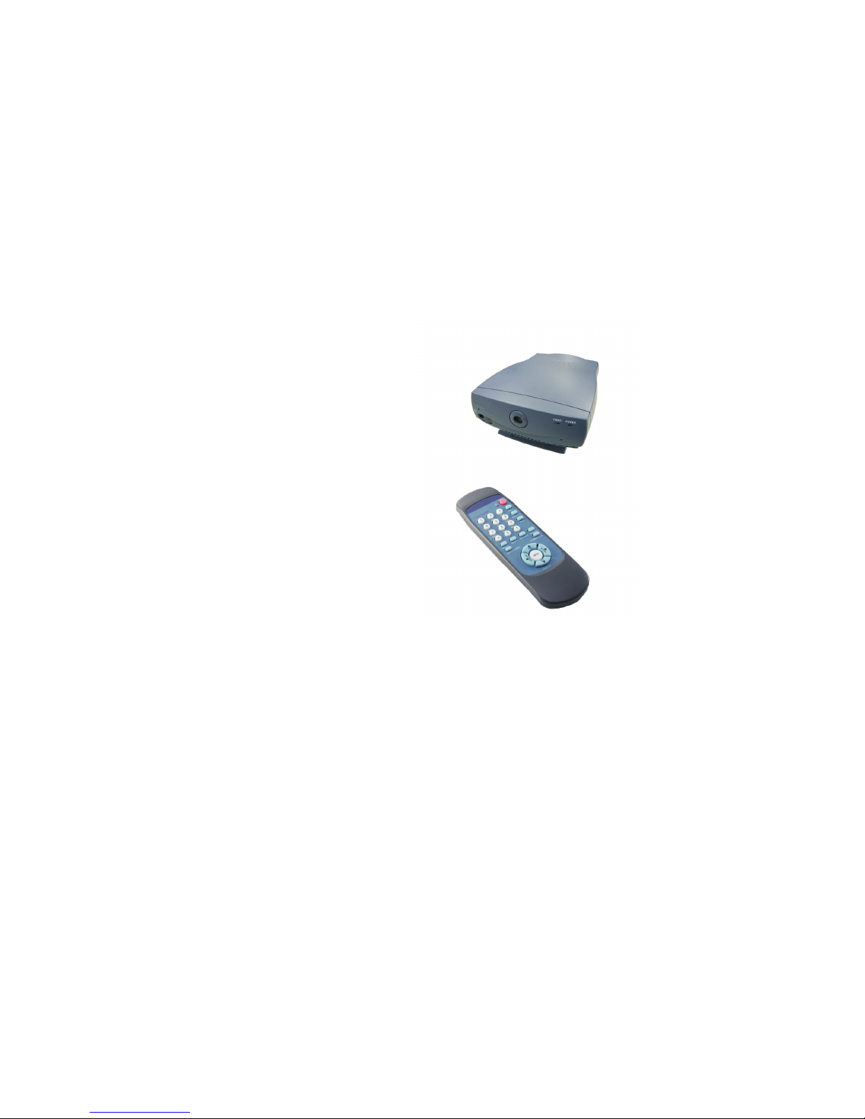
IP Videophone STB
User's Manual
Page 2

IP Videophone STB User's Manual
Version A
April 2004 P/N: W0500879
Page 3

Table of Contents
1 Getting Started ...................................................... 1
2 Getting to Know Your Videophone ..................... 3
3 Installation ............................................................ 8
Overview ........................................................................ 1
Feature highlights ........................................................... 1
What's in the package ..................................................... 2
Front view ....................................................................... 3
Rear view ........................................................................ 4
Using remote control ...................................................... 5
Installing the unit ............................................................ 8
Using external devices .................................................. 11
4 Making a Call ....................................................... 12
5 Making Adjustments .......................................... 14
Before making a video call ........................................... 12
Making a video call ...................................................... 13
Using OSD menus ........................................................ 14
Reviewing IPs ................................................................ 15
Configuration .................................................................. 16
Password Checking .......................................................... 16
Phone Setup ...................................................................... 17
Network Setup .................................................................. 18
Bandwidth Setup ............................................................... 19
Advanced Setup ................................................................ 20
Firmware Update .............................................................. 23
Configuration Changed ..................................................... 26
Page 4

Table of Contents
Error messages in bootup sequence .............................. 36
Other problems ............................................................. 39
Phonebook ....................................................................... 27
Change Password ............................................................ 33
Restore factory settings ................................................... 34
Add ................................................................................... 27
Search ............................................................................... 28
InBox ................................................................................ 31
OutBox ............................................................................. 32
6 OSD Menu Tree ................................................... 35
7 Trouble Shooting ................................................ 36
8 FCC Statement ................................................... 40
Error messages in dialing sequence .............................. 38
Page 5

Overview
Feature highlights:
The Videophone is designed to avoid complicated installation. And with the
buttons on the remote control, you are able to access the user-friendly on
screen display menu (OSD), easily control the functions and make
adjustments.
The Videophone has a built-in high quality CCD camera. Images are
transmitted through the Internet at up to 24 frames per second (fps)
. While making a video call, you can enjoy the brilliant real-time
color images of yourself, your correspondents or both. If you do not want
your image to display on the caller or receiver's screen, Videophone's private
mode can do just that.
The Videophone is fully compliant with H.323 international standards for
video communication. It can be used with any videophone that are
compatible with this standard.
Broadband IP address videophone
Connect the other videophone by simply entering the IP address/number*
Friendly and easy operation through remote control
Phonebook dialing function
2 A/V inputs & 1 A/V output for additional video/audio input and
video/audio output
Up to 24 frames per second video display (@ CIF resolution)
Video selectable and picture image up to VHS quality
Echo-cancellation and no delay high quality audio
(@ CIF
resolution)
Built-in high quality CCD camera
1Getting Started
1
*Note: To dial numbers, Videophone must work in conjunction
with additional accessories, such as the H.323 Gatekeeper.
Page 6
Audio/Video Cable
Power Adapter
Ethernet Cable
User's Manual
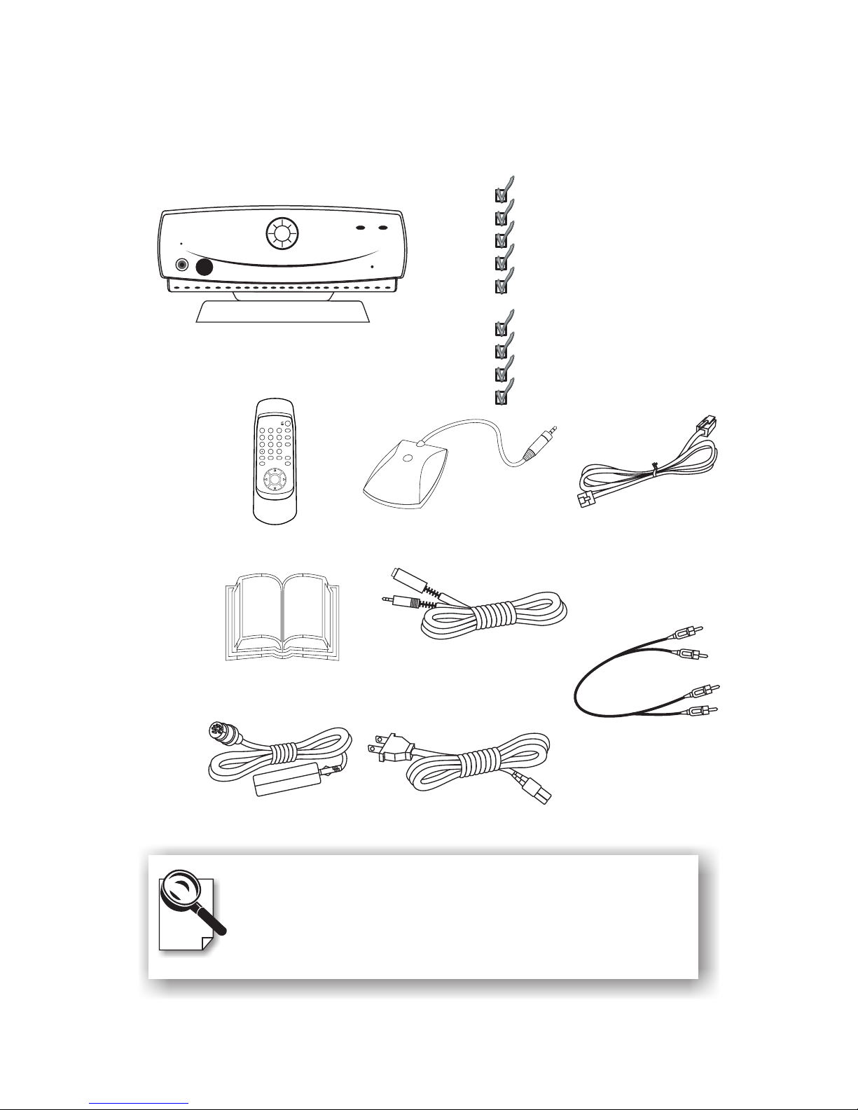
What's in the package?
Please unpack the product package with caution; inspect
the Items closely. If you find any damaged item, please
contact your local distributor immediately. Also, please keep
the box and packing material for future use in the event of
future shipments.
IP Videophone STB User's Manual 2
Power Cord
Videophone
Videophone x1
Remote Control x1
User's Manual x1
Microphone x1
Microphone Extension
Cable x 1
Power Adapter x1
Power Cord x1
Ethernet Cable (RJ-45) x1
Audio/Video Cable x1
2
3
4
5
6
789
0
1
VOL
#
VOL
OK
S
H
A
R
P
F
A
S
T
Y0400033
.,
!;
PQRS
TUV
STILL
ABC DEF
PRIVACY
GHI
JKL
MNO
VIEW
WXYZ
CAMERA
MUTE IN-BOX OUT-BOX
PHONEBOOKCLEAR
Remote Control
Microphone
MIC
VIDEO POWER
Microphone
Extension
Cable
Page 7
2Getting to Know Your Videophone
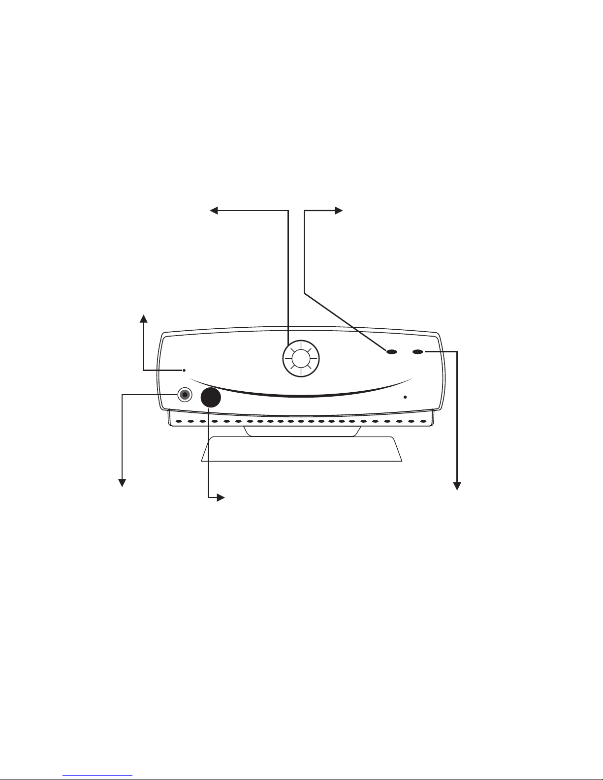
Front view
3
CCD Camera:
The input source of
local video image. This
is a mini built-in CCD
camera.
Power Indicator:
Lights green when the
power is on.
Video Indicator:
Lights orange when the main
unit is in video transmission.
When Videophone is in audio
mute (see p. 6), the video
indicator blinks.
Microphone
Connector:
You need to
connect the
external
microphone here
in order to input
voice.
Remote Control
Signal Receiver:
Receives the infrared
signal from the remote
control. When using
the remote control,
please aim at this
receiver.
Buzzer
MIC
VIDEO POWER
Page 8
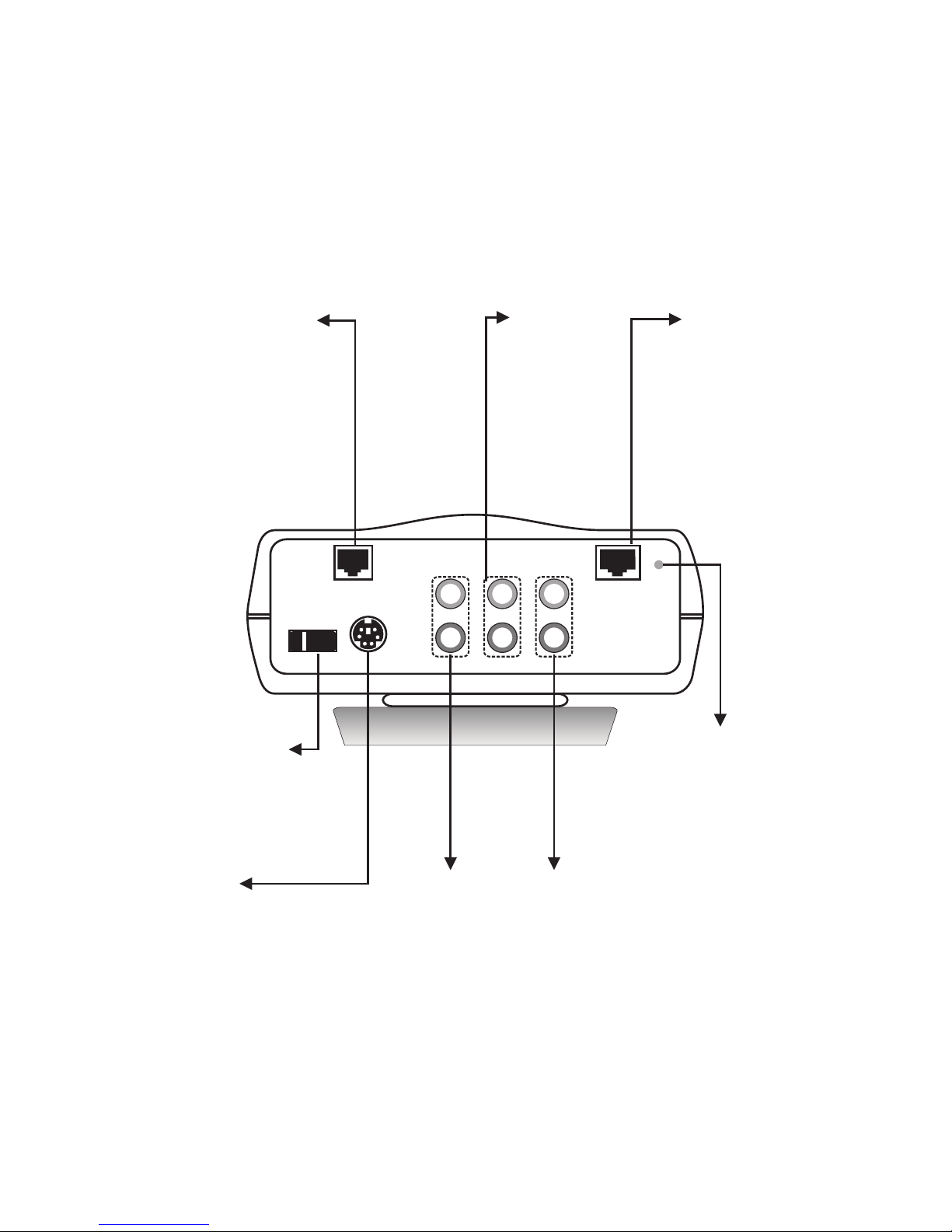
Rear view
COM
(reserved)
DC IN
Connect to the
DC output of
power adapter
A/V Input 1
Audio and
Video input
connector 1
WA N
Ethernet
connector
Power Switch
For turning
on/off the power
ON
COM
OFF
POWER
WAN
AV OUT
AV IN2 AV IN1
Audio
Video
LINK
LINK
Network
activity
indicator
A/V Output
Audio and
Video output
connector
A/V Input 2
Audio and
Video input
connector 2
IP Videophone STB User's Manual 4
Page 9
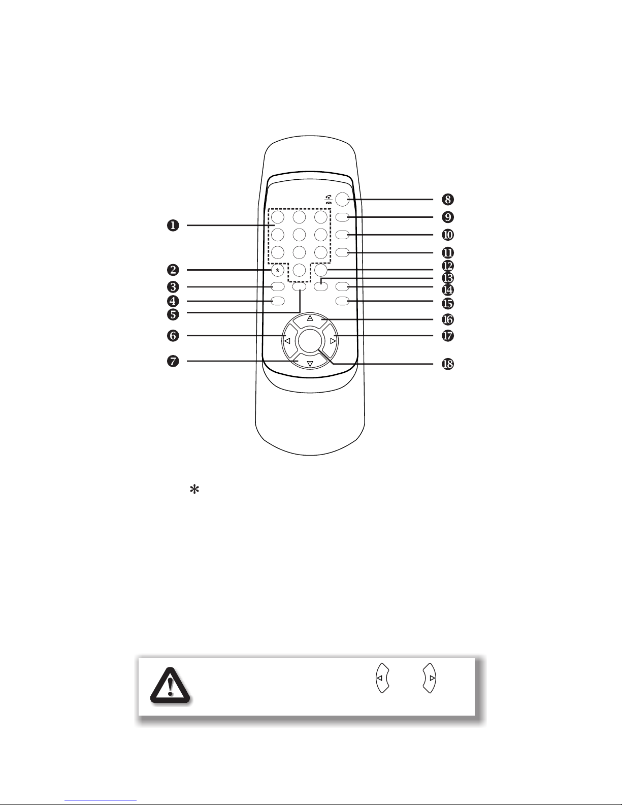
Using remote control
1. Number keys
2.
3. Mute
4. Clear
5. IN-BOX
6. Left arrow
7. Vol -
8. On-hook / Off-hook
9. Still
10. Privacy
11. View
12. #
13. OUT-BOX
14. Camera
15. Phonebook
16. Vol +
17. Right arrow
18. OK
5
VOL
VOL
OK
S
H
A
R
P
F
A
S
T
Y0400033
2
3
4
5
6
789
0
1
#
.,
!;
PQRS
TUV
ABC DEF
GHI
JKL
MNO
WXYZ
CLEAR
MUTE IN-BOX OUT-BOX
PHONEBOOK
CAMERA
VIEW
PRIVACY
STILL
@
F
A
S
T
S
H
A
R
P
The "FAST" and "SHARP" on and are
not applicable in this product.
Page 10
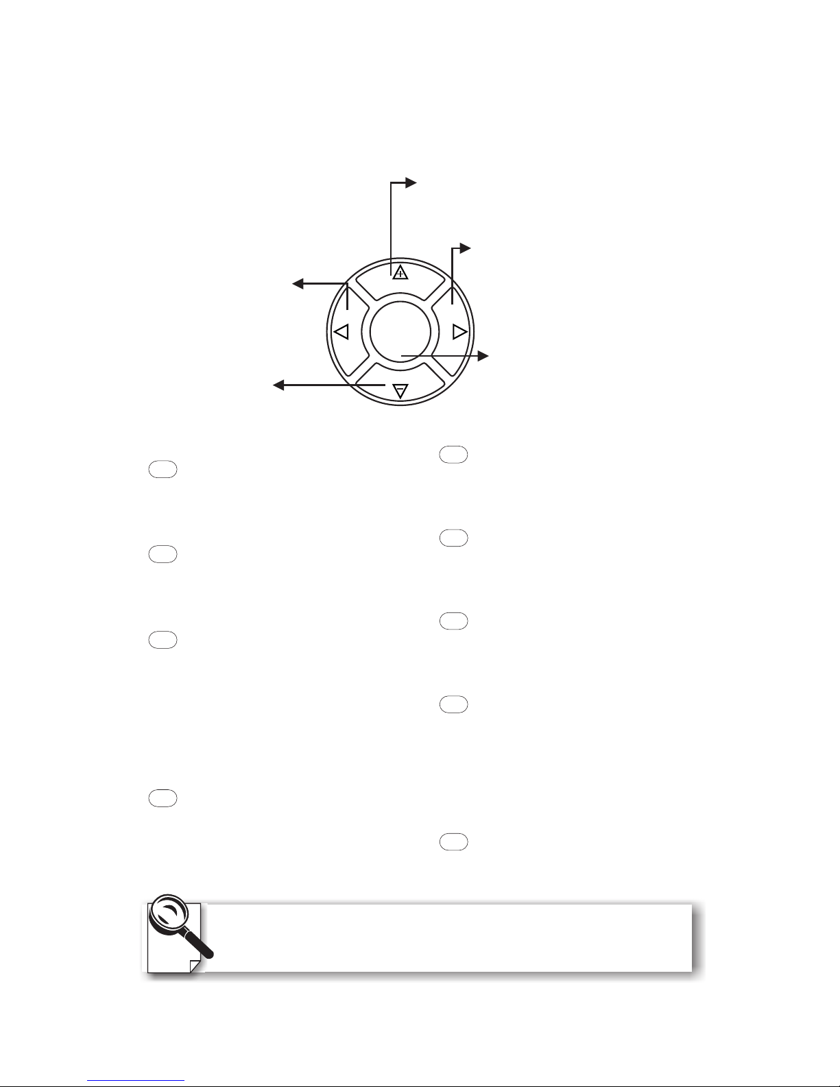
Used with OSD menus; to move
the cursor left or to go back to
the previous menu. During a
video call, used to reduce the
incoming video bit rate.
OK: Used with OSD menus; to
pop up the OSD menu, to enter
the sub menu, or to confirm the
selection. During a video call,
related to the "Allow Remote
Control" option (see page 17).
Used with OSD menus; to move
the cursor right or to enter the sub
menu. During a video call, used to
raise the incoming video bit rate.
Used with OSD menus; to move the
cursor up. During a call, to turn the
volume of the speakerphone up.
Used with OSD menus; to
move the cursor down.
During a call, to turn the
volume of the
speakerphone down.
VOL
VOL
OK
S
H
A
R
P
F
A
S
T
Still:
To freeze the video image of
yourself so that the other party
can have a clearer display.
STILL
Camera:
To switch between the built-in
CCD camera and external
cameras connected to Videophone.
CAMERA
MUTE
Mute:
During a video call, this button
is used to mute the audio so that
you will not be heard by the
other party on the phone.
VIEW
View:
To select how local and remote
video is displayed on the screen.
The options are: Remote, PIP
upper-left, PIP lower-left, PIP
upper- right, PIP lower-right,
Local. And it switches in that
sequence.
CLEAR
Clear: To go back to the
previous menu, or to function as
Backspace when you input letters
or numbers. During a video call,
to refresh the screen should
artifacts appear due to temporary
network traffic congestion.
To dial phone numbers, Videophone must work in conjunction
with additional accessories, such as the H.323 Gatekeeper.
Cursor Panel
Hot Keys
PHONEBOOK
Phonebook:
To bring out the phonebook
menu. See page 27.
PRIVACY
Privacy:
Stop sending your image to the
other side so that you will not be
seen by the person you talk to.
IN-BOX
IN-BOX:
To bring out the menu that
contains the numbers of the 10
last received calls.
OUT-BOX
OUT-BOX:
To bring out the menu that
contains the numbers of the 10
last dialed calls.
Using remote control
(cont.'d)
IP Videophone STB User's Manual 6
Page 11
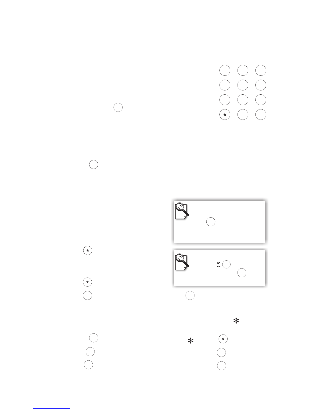
Inputting numbers
Pressing any key on the numeric keypad can input the
correspondent number.
For example, pressing will generate the number"8".
Numeric Keypad
Numeric Keypad
Inputting letters
Every button on the numeric keypad has characters printed on
it, in addition to the numbers. Number keys from"2"to"9"
have English letters below them, so they can be used to input English letters.
When inputting data, pressing a key consecutively will generate the letters on it.
For example, has the number"7"onitandtheletters " PQRS " below it.
Pressing this key once will generate the number"7".
Pressing this key twice consecutively will generate the letter"P".
Pressing this key three times will generate the letter"Q",four times the letter
" R ", and five times the letter"S".
And it will cycle in such order.
Inputting punctuation marks
The keypad provides four punctuation marks:
" " " " " " and " ".
.,! ;
" ": Press twice consecutively;
" ": Press three times consecutively.
" ": Press twice consecutively. " ": Press three times consecutively.
.
,
!;
Press only once to generate"."
when inputting IP addresses.
Inputting special characters
The keypad also provides six special characters: " " " " " " " " " "
and " ".
@_- $
#
" ": Press twice consecutively; " ": Press once.
" ": Press three times consecutively. " ": Press 4 times.
" ": Press four times consecutively. " ": Press once.
@
_$
-#
2
3
4
5
6
9
1
#
.,
0
!;
7
PQRS
8
TUV
ABC DEF
GHI
JKL
MNO
WXYZ
Using remote control
(cont.'d)
@
.,
.,
0
!;
0
!;
1
@
1
@
1
@
.,
0
!;
#
Switching between upper
case and lower case letters
Press once to switch
between upper and lower case
letters when inputting data.
#
8
TUV
7
PQRS
7
Speed Dial
When the button is
pressed, pressing can
enable speed dial.
#
Page 12
Front view
Side view
A
C
B
3Installation
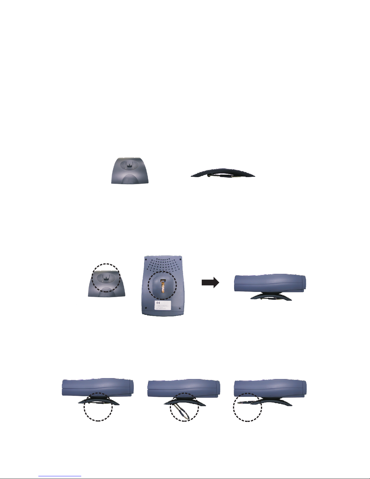
Installing the unit
Step 1 Installing the skid-proof base
The enclosed skid-proof base keeps the unit securely positioned
anywhere on the flat surfaces.
1. Attach the base to the unit by sliding the security latch of the
base into the corresponding area on the bottom of the unit.
2. Move the weight stabilizer from position A to position C to
provide extra weight support and balance.
IP Videophone STB User's Manual 8
Page 13

MIC
VIDEO POWER
Step 2 Pick a good spot
Prolonging the lifespan
Avoid storing or operating Videophone in abnormal conditions.
High temperatures or excessive humidity could cause the unit to
malfunction and shorten its useful lifespan.
Stability
Place your Videophone on top of a counter, desk, or table with the
CCD camera opening in front.
Lighting condition
Make sure the lighting is sufficient and does not shine directly
into camera lenses.
View of camera
Avoid using Videophone in a room with brightly painted walls or
flamboyant wallpaper. Soft and evenly painted background
provides the best results.
Connect the microphone.
Step 3 Connect the microphone
Plug the included microphone into the MIC connector in the front
of Videophone. If you find the cord a tad short, use the supplied
Microphone Extension Cable to extend the length of the
microphone and provide additional distance.
Installing the unit
9
Page 14
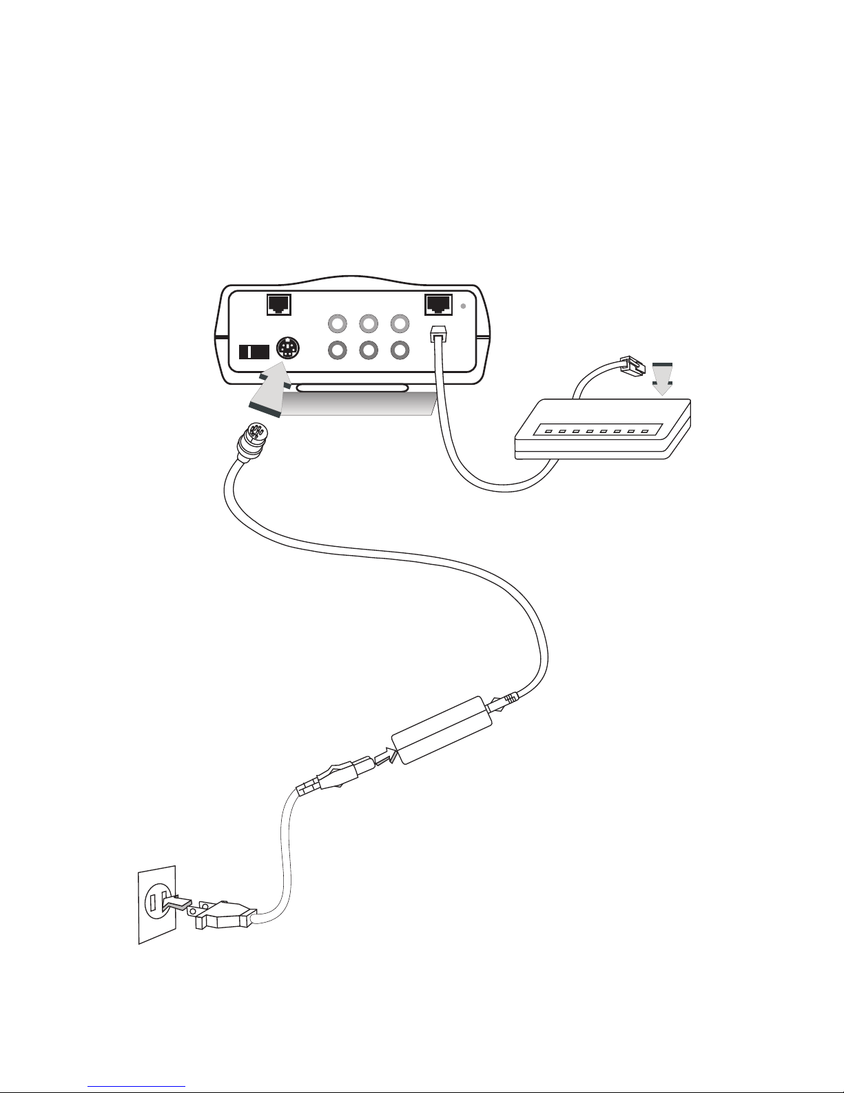
Step 4 Connect the Ethernet cable
Plug one end of the Ethernet cable in the jack marked "WAN" on
Videophone. Plug the other end of the Ethernet cable in the RJ-45
jack of the Internet device (hub, router, or ATU-R).
Installing the unit
Step 5 Plug in for power
Connect the power cord between
the wall outlet and the power
adapter. Plug the free end of the
power adapter into the power
connector (DC IN) on
Videophone.
Connect
the power
adapter.
Connect the power cord
and plug in.
ON
COM
OFF
POWER
WAN
AV OU T
AV IN 2 AV IN1
Audio
Video
LINK
Connect the
Ethernet cable
to the Internet
device.
IP Videophone STB User's Manual 10
Page 15

Using external devices
VCR
(for recording)
VCR
(for playing)
A/V Output
OR
OR
CCD Camera
Television
VCR
(for playing)
OR
CCD Camera
ON
COM
OFF
POWER
WAN
AV OUT
AV IN2 AV IN1
Audio
Video
LINK
A/V Input 1
A/V Input 2
11
Page 16

Avoid having lights behind you that
might shine into the camera lens.
Do not point the Videophone at a
mirror or bright light.
Keep a distance of 0.5 meters away
from Videophone.
Make sure of the most appropriate
lighting source, preferably from
the front with the beam on your
face.
4Making a Call
Here are a few things you need to consider before making a video call.
Use the self-view image to get the best shot of yourself.
Before making a video call
Avoid having a lot of movement in the background and try not to move
around excessively. Too much movement tends to slow down the frame
rate of the video image, resulting in a jerky picture.
1
3
24
5
6
0.5 m
IP Videophone STB User's Manual 12
Page 17

Step 1 Turn on the power of the unit and
.
Step 2 Press the button.
Step 3 The other party answers the phone, and
Step 4
Step 5
make sure Videophone is
connected with TV The external TV screen shows the local view,
the image of the caller.
Enter the desired IP address/number * (See
note). Use the key to input the dots between the numbers. When
a key is pressed, the image on the TV screen disappears and the
numbers you input are displayed.
the video connection is
established. You will be able to see the person you are talking to.
To end the connection, press the button.
If there is difficulty in making connection, please make sure that
Videophone has been properly installed. Please also check if the
network settings are correctly configured.
Making a video call
.,
*Note: To dial numbers, the Videophone must work in
conjunction with additional accessories, such as the H.323
Gatekeeper.
If there are artifacts residuals on the screen due to
network traffic congestion, press button to
refresh the screen.
13
CLEAR
Page 18

Using OSD menus
Videophone allows you to use the cursor panel on the remote control to
operate OSD (on-screen-display) menus. The OSD menu is brought out by
pressing the button on the cursor panel of the remote control. The figure
below shows you what an OSD menu looks like:
OSD menu
TV
Screen
Cursor Panel
Operating OSD menus cursor panel explained
Highlighted item
5Making Adjustments
VOL
VOL
OK
S
H
A
R
P
F
A
S
T
OK
OK
Brings up on-screen menu, enter the
submenu, or confirm the selection made.
F
A
S
T
Moves the cursor right or enter the
submenu.
VOL
Moves the highlighted option down.
VOL
Moves the highlighted option up.
S
H
A
R
P
Moves the cursor left or go back to the
previous menu.
Configuration
Change Password
Phonebook
IP Videophone STB User's Manual 14
Page 19

Change Password
Configuration
Phonebook
xxx.xxx.xxx.xxx
Firmware version:
Press "OK" to enter
IP addr of this phone:
Phone can be called by
xxx.xxx.xxx.xxx
the Configuration menu.
Main: 1.1.0
LAN: 2.2.2
Local view
Using OSD menus Reviewing IPs
(Continued on page 16, 27, 33
respectively, for instructions on
configuring different settings)
OK
OK
15
Page 20

Bandwidth Setup
Firmware Update
Phone Setup
Password correct?
Ye s
Change Password
Configuration
Phonebook
Please enter password
|
Network Setup
Advanced Setup
Incorrect password
Any key
(Continued on page 17 to 25
respectively, for instructions on
configuring different settings)
Numeric input,
maximum 4 digits
No
Using OSD menus
Password Checking
Configuration
and : Item selection
VOL
VOL
or
OK
F
A
S
T
OK
: backspace
CLEAR
IP Videophone STB User's Manual 16
Page 21

Using OSD menus Configuration Phone Setup
Phone Setup
Auto Answer Rings (0~9): 4
Ring Volume: HI
Start With: Both A&V
Flash Key: OFF
H.263: ON
Auto Answer: OFF
Allow Remote Control: NO
Start With:
Flash Key:
Allow Remote Control:
Both A&V:
Video:
Audio:
ON:
YES:
Starts a call with both audio and video.
Starts a call with video only. Audio is disabled.
Starts a call with audio only. Local view is on the TV. To bring
back video during the call, press the key.
Pressing the key during a call sends a Hook-Flash signal.
Flash is used to access features in a PBX phone system.
Allows the remote (far) site to change the video input sources on
this phone during a call. The remote site first presses , then each
subsequent press of changes the video source. The letters "Alt"
is displayed on the TV after is pressed.
H.263: If two parties have a communication problem with the video
protocol, setting H.263 to off may solve the problem.
Numeric keypad: input numbers
and : Item selection
VOL
VOL
: toggle options
(ON/OFF, HI/LO,
YES/NO)
and
S
H
A
R
P
F
A
S
T
PRIVACY
PHONEBOOK
CAMERA
OK
OK
17
Page 22

Network Setup
IP Address: 0.0.0.0
Netmask: 255.255.255.0
Gateway: 192.168.1.1
Press > to check: ( )
Being Called by Above IP? NO
Auto Get IP (DHCP)? YES
User Name: Videophone
Use Phone #? NO
Phone #: 123456
Auto Get IP?
Being Called by Above IP?
User Name:
Use Phone #?
YES:
NO:
YES:
NO:
YES:
IP Address, Netmask and Gateway for the phone unit will be
provided by a DHCP server. The typical case for this selection is when
the phone is connected to a router which includes a DHCP server.
A user enters the IP Address, Netmask and Gateway. The typical
case for this selection is when the user wants to assign a public and static
IP to the phone unit.
The IP address to be used in receiving calls is specified in the IP
Address field above. The typical case for this selection is when the IP
address is public and static, therefore, reachable directly from the
Internet.
The IP address to be used in receiving calls can be found in the
Public IP Address menu (see page 21). The typical case for this selection
is when a phone is connected to a router which performs a NAT function.
Your ISP assigns a public IP address to your router. By using this public
IP address, your phone is reachable directly from the Internet.
The user name is displayed when the phone rings.
Phone # is another way for someone to call your phone. To use the
Phone # feature, your phone must be registered successfully to a
Gatekeeper with your desired phone #. Gatekeeper is set up in the
Gatekeeper menu .(see page 20)
Using OSD menus Configuration Network Setup
Numeric keypad: input numbers,
letters, punctuation marks, and
special characters.
and : Item selection
VOL
VOL
: toggle options
(YES/NO)
and
S
H
A
R
P
F
A
S
T
IP Videophone STB User's Manual 18
Page 23

Bandwidth Setup
Outgoing Network Bandwidth:
Incoming Network Bandwidth:
Choices are 128, 256, 384, 512, 640 Kbps. The Outgoing Network
Bandwidth refers to the total bandwidth speed for your broadband
connection from your location to Internet. It is also known as the Upload
or Upstream speed. You should select a speed to match your broadband
network, For example, if you have a DSL with 128 Kbps upload speed,
select 128 Kbps here. Note the Outgoing and Incoming speeds do not
have to be the same.
Choices are 128, 256, 384, 512, 640 Kbps. The Incoming Network
Bandwidth refers to the total bandwidth speed for your broadband
connection from Internet to your location. It is also known as the
Download or Downstream speed. You should select a speed to match
your broadband network. For example, if you have a DSL with 1.5 Mbps
download speed, select 640 Kbps here. Note the Outgoing and Incoming
speeds do not have to be the same.
During a call, you can fine tune the incoming speed by pressing and
keys.
Using OSD menus Configuration Bandwidth Setup
Incoming Network Bandwidth:
Outgoing Network Bandwidth:
256 Kbps
256 Kbps
Bandwidth Setup
Firmware Update
Phone Setup
Network Setup
Advanced Setup
and : Item selection
VOL
VOL
and : Item selection
VOL
VOL
and
: Set the bandwidth
S
H
A
R
P
F
A
S
T
S
H
A
R
P
F
A
S
T
19
OK
or
OK
F
A
S
T
Page 24

Using OSD menus Configuration Advanced Setup
Advanced Setup
Alias: Videophone
GateKeeper: 192.168.128.110
Keep Alive: ON
GK Password ( )
Public IP Address
Update Server
PPPoE
GateKeeper
Hot Link
Gatekeeper:
You need to get the IP of the gatekeeper from your gatekeeper service
provider.
Keep Alive:
Alias:
GK Password:
If your gatekeeper service provider periodically inquires for your
Videophone's online status, you can set Keep Alive to ; if it doesn't
make such an inquiry and you want to stay online for a long period of
time, it is better to set Keep Alive to . Consult your gatekeeper
service provider if you don't know how to do Keep Alive setting.
The
GK Password is set according to your gatekeeper service provider's
requirements.
OFF
ON
alias may be assigned by your gatekeeper service provider.
and : Item selection
VOL
VOL
and : Item selection
VOL
VOL
Numeric keypad: input numbers,
letters, punctuation marks, and
special characters.
Clear
: backspace
and
: move cursor,
toggle options
(ON/OFF)
S
H
A
R
P
F
A
S
T
IP Videophone STB User's Manual 20
OK
or
OK
F
A
S
T
Page 25

Public IP Address
Update Server
PPPoE
GateKeeper
Hot Link
Public IP: 192.168.128.179
IP Server: 210.202.38.143
Auto Detect Public IP? YES
Numeric keypad: input numbers
Advanced Setup
Using OSD menus Configuration Advanced Setup
IP Server:
Auto Detect Public IP?
YES:
NO:
The public IP address assigned to your router by your ISP will be
detected automatically and shown after reboot. See the Network Setup
menu (p.18) on how to use the public IP address.
You can assign your own public IP address.
IP Server is a server which your service provider places on the Internet.
This server assists your videophone to automatically detect the public IP
address assigned to it. Do not change this value unless instructed by your
service provider.
Public IP Address
Update Server
PPPoE
GateKeeper
Hot Link
Update Server:
65.215.224.51
and : Item selection
VOL
VOL
and : Item selection
VOL
VOL
OK
or
OK
F
A
S
T
OK
Numeric keypad: input numbers.
and
: move cursor
S
H
A
R
P
F
A
S
T
: backspace
CLEAR
and : Item selection
VOL
VOL
: toggle options
(YES/NO)
and
S
H
A
R
P
F
A
S
T
and : Item selection
VOL
VOL
or
OK
F
A
S
T
21
Page 26

Using OSD menus Configuration Advanced Setup
Advanced Setup
Public IP Address
Update Server
PPPoE
GateKeeper
Hot Link
PPPoE: OFF
PPPoE Username ( )
PPPoE Password ( )
Hot Link: OFF
Hot Link Number ( )
Hot Link:
ON: The Hot Link number will be used for dialing when the handset is
raised or when the key is pressed. This is useful when a certain
number must be dialed whenever the phone is in use.
Public IP Address
Update Server
PPPoE
GateKeeper
Hot Link
PPPoE:
If you use timing ADSL to connect to Internet directly, please set PPPoE
to . You can get PPPoE Username and Password from your ISP.ON
and : Item selection
VOL
VOL
and : Item selection
VOL
VOL
and : Item selection
VOL
VOL
OK
or
OK
F
A
S
T
IP Videophone STB User's Manual 22
OK
or
OK
F
A
S
T
Numeric keypad: input numbers,
letters, punctuation marks, and
special characters.
and
: toggle options
(ON/OFF)
S
H
A
R
P
F
A
S
T
Page 27

Using OSD menus Configuration Firmware Update
Firmware Update
Start Firmware Update?
Yes <OK>
No <CLEAR>
Are you sure?
Yes <OK>
No <CLEAR>
Bandwidth Setup
Firmware Update
Phone Setup
Network Setup
Advanced Setup
YES
Reboot.
and reboot.
Firmware Update.
Press "OK" to turn off
the "Use Phone #?" feature
After reboot, please retry
NO
See next page.
Use Phone #?
You can check the
"Use Phone #?"
state in
under
menu.
Network
Setup
Configuration
CLEAR
CLEAR
OK
OK
OK
and : Item selection
VOL
VOL
or
OK
F
A
S
T
23
Page 28

Using OSD menus Configuration Firmware Update
successfully. Restarting.
Firmware Update completed
Main S/W
Update in progress.
Please wait...
Firmware Update
LAN S/W
Update in progress.
Please wait...
latest firmware.
You already have the
Connection time out.
Retry <OK>
Abort <CLEAR>
Firmware
versions are
the same
Wait 5
seconds
Unsuccessful
connection
Unsuccessful
connection
(Continued from previous page)
Bandwidth Setup
Firmware Update
Phone Setup
Network Setup
Advanced Setup
Wait 5 seconds,
reboot.
LAN code
changed
YES
NO
See next page.
OK
OK
CLEAR
IP Videophone STB User's Manual 24
Page 29

Using OSD menus Configuration Firmware Update
Firmware Update
Finalizing Firmware Update.
Please do not touch the phone.
The phone will restart
automatically.
Wait for firmware
written into flash,
reboot.
(Continued from previous page)
Do not touch the phone during firmware update.
The phone will reboot itself after the update.
Turning off the phone pre-maturely may cause a
permanent failure and require a factory service.
25
Page 30

Using OSD menus
Save the settings?
Yes <OK>
No <CLEAR>
Configuration
Configuration has
been changed?
No
Ye s
Saving completed.
Restarting...
Configuration Changed
Local view
Change Password
Configuration
Phonebook
Saving in progress.
Please do not touch the phone.
Reboot.
S
H
A
R
P
CLEAR
OK
IP Videophone STB User's Manual 26
Page 31

Using OSD menus Phonebook Add
Adding to the phonebook
and : Item selection
VOL
VOL
and : Item selection
VOL
VOL
S
H
A
R
P
or
F
A
S
T
OK
OK
OK
CLEAR
Search
InBox
Add
OutBox
Speed Dial
Record Saved
Numeric keypad: input numbers,
letters, punctuation marks, and
special characters.
and : Item selection
VOL
VOL
and
: move cursor
S
H
A
R
P
F
A
S
T
: backspace
CLEAR
Change Password
Configuration
Phonebook
Add This Record?
Yes <OK>
No <CLEAR>
Name: |
Phone No:
IP:
H.323 Alias:
Note:
You can enter the phonebook
menu either through the OSD
menu or by pressing the
button
If you enter the phonebook
menu by pressing the
at any time.
button, Videophone
will return to local view when
you leave the phonebook menu.
PHONEBOOK
PHONEBOOK
27
or
OK
F
A
S
T
Page 32

Using OSD menus Phonebook Search
Search for a number
and : Item selection
VOL
VOL
or
OK
F
A
S
T
Search for a number
Dial
Edit
Delete
(Continued on next page)
Searching by Name:
Joe
Name: Joe
Phone No. : 789
IP: 192.168.3.1
H.323 Alias: Joe
Add to Speed Dial
Search
InBox
Add
OutBox
Speed Dial
OK
Clear
: backspace
Numeric keypad: input numbers,
letters, punctuation marks, and
special characters.
and
: move cursor
S
H
A
R
P
F
A
S
T
IP Videophone STB User's Manual 28
Page 33

Using OSD menus
Search for a number (cont'd)
Dial the searched number
Phonebook Search
Call progressing
Updating ...
Edit the phonebook record
and
: move cursor
S
H
A
R
P
F
A
S
T
: backspace
CLEAR
and : Item selection
VOL
VOL
and : Item selection
VOL
VOL
OK
Dial
Edit
Delete
Add to Speed Dial
Dial
Edit
Delete
Add to Speed Dial
Dialing ...
192.168.3.1
Name: |Joe
Phone No. : 789
IP: 192.168.3.1
H.323 Alias: Joe
or
OK
F
A
S
T
or
OK
F
A
S
T
Numeric keypad: input numbers,
letters, punctuation marks, and
special characters.
and : Item selection
VOL
VOL
If you can not dial out with
Videophone, please hang up
or press the button to
return to local view, and try
to dial again.
29
Page 34

Using OSD menus
Search for a number (cont'd)
Phonebook Search
Delete This Record?
YES <OK>
NO <CLEAR>
Record deleted
Delete the phonebook record
Dial
Edit
Delete
Add to Speed Dial
Record saved
Dial
Edit
Delete
Add to Speed Dial
0. (None)
1. (None)
2. (None)
3. (None)
4. (None)
Add the record to Speed Dial
OK
OK
OK
and : Item selection
VOL
VOL
and : Item selection
VOL
VOL
Press the item number (0-9) to
assign the record to the number.
and : Item selection
VOL
VOL
IP Videophone STB User's Manual 30
Page 35

Using OSD menus Phonebook InBox
InBox contains the numbers of the 10 last received calls.
Dial out
By (IP / Phone no. / Alias)
Dialing to (Name) ...
Dial out
and : Item selection
VOL
VOL
and : Item selection
VOL
VOL
or
S
H
A
R
P
F
A
S
T
OK
OK
S
H
A
R
P
VOL
VOL
Select a desired item and
then press , or press a
number directly, to dial out.
OK
5. 25478654 (00:03:21)
6. Mary (00:01:16)
7. 12547869 (00:02:37)
8. Tom (00:08:18)
9. 52458745 (00:07:24)
0. 24586547 (00:02:15)
1. 35648755 (00:01:20)
2. Amy (00:32:47)
3. Tom (00:51:30)
4. 25478654 (00:01:38)
Search
InBox
OutBox
Add
Press to clear In/Out Box
****
Speed Dial
Change Password
Configuration
Phonebook
If you can not dial out with
Videophone, please hang up or press
the button to return to local
view, and try to dial again.
31
Page 36

Using OSD menus
OutBox contains the numbers of the 10 last dialed calls.
Phonebook OutBox
or
Dial out
By (IP / Phone no. / Alias)
Dialing to (Name) ...
Dial out
and : Item selection
VOL
VOL
and : Item selection
VOL
VOL
S
H
A
R
P
F
A
S
T
OK
S
H
A
R
P
VOL
VOL
Select a desired item and
then press , or press a
number directly, to dial out.
OK
5. 25478654 (00:03:21)
6. Mary (00:01:16)
7. 12547869 (00:02:37)
8. Tom (00:08:18)
9. 52458745 (00:07:24)
0. 24586547 (00:02:15)
1. 35648755 (00:01:20)
2. Amy (00:32:47)
3. Tom (00:51:30)
4. 25478654 (00:01:38)
Search
InBox
OutBox
Add
Press to clear In/Out Box
****
Speed Dial
OK
Change Password
Configuration
Phonebook
If you can not dial out with
Videophone, please hang up or press
the button to return to local
view, and try to dial again.
IP Videophone STB User's Manual 32
Page 37

Password changed
Using OSD menus
change failed
Check inputs
Change Password
Old password: |
Confirm:
Any key
Change Password?
Yes <OK>
No <CLEAR>
New password:
Invalid
Valid
Invalid input, Password
Change Password
Configuration
Phonebook
and : Item selection
VOL
VOL
or
OK
F
A
S
T
CLEAR
OK
OK
Numeric input: maximum
4 digits
and
: move cursor
S
H
A
R
P
F
A
S
T
: backspace
CLEAR
33
Page 38

Local view
********
In local view screen, pressing "********" (eight asterisks) will bring out a
dialog window, asking if you want to restore all settings to factory default
(see below). Press to begin the process. Press to cancel.
Restore all settings
to factory default?
Yes <OK>
No <CLEAR>
Using OSD menus Restore factory settings
Restoring all settings.
Please wait...
Settings restored.
Restarting.
Reboot.
OK
CLEAR
CLEAR
OK
IP Videophone STB User's Manual 34
Page 39

6OSD Menu Tree
Change Password
Firmware Update
Search
InBox
OutBox
Add
Phonebook
Speed Dial
Network Setup
Advanced Setup
GateKeeper
Public IP Address
Update Server
Hot Link
PPPoE
Configuration
Local view
Phone Setup
Bandwidth Setup
35
Page 40

7Trouble Shooting
Error messages in bootup sequence
Please enter a phone #,
press "OK" to continue.
To skip, press "CLEAR"
Public IP server address is
invalid, please assign.
Press "OK" to continue.
If the screen to the left is displayed
after bootup, it means that you
have set "Use Phone #?" to Yes but
the phone # is not given. Please
enter the phone # and press
to register with the gatekeeper.
If the screen to the left is displayed
after bootup, it means that Public
IP Server address is invalid. It is
recommended to restore the
factory default setting.
Public IP address is
invalid, please assign.
Press "OK" to continue.
If the screen to the left is displayed
after bootup, it means that the
Videophone needs an IP address,
but the current setting is invalid.
Please assign a Public IP address.
PPPoE is on, please
assign a user name
Press "OK" to continue.
and password.
If the screen to the left is displayed
after bootup, it means that you are
using PPPoE but you did not enter
the PPPoE user name and
password. Please assign the PPPoE
user name and password.
OK
IP Videophone STB User's Manual 36
Page 41

Duplicated IP address
for this phone.
Please reassign.
If the screen to the left is displayed
after bootup, it means that the IP
address of the Videophone is
duplicated with that of another
device in the same local area
network. Please assign a new IP
address for the Videophone.
Error messages in bootup sequence
37
Page 42

xxx
is an invalid IP address.
Please try again.
Error messages in dialing sequence
If the screen to the left is displayed
after you dial an IP address, it
means the IP address is invalid.
Please retry with a correct one.
IP Videophone STB User's Manual 38
Page 43

Plug power cord in the power
outlet in the wall.
Plug the power adapter in the
unit.
Turn on the power switch.
Power Indicator OFF
Make sure the power indicator
is ON, and select the
appropriate video input for TV.
No image is displayed on TV
screen
Plug RJ-45 cable from the
Internet device into "WAN"
jack on the unit.
Can not dial an IP address
Increase light on the image
and reduce back lighting.
Video of local view is dark
Aim the Videophone at a
strong white light source
momentarily.
Increase the room light level.
Video in local view has a red cast
Hang up and call again.
Make sure the remote video
phone is compatible with
H.323 standard.
Ask the other party call you.
Video connection is not
established correctly
Probable cause is bad
connection (noisy line). Hang
up and try again. This time,
ask the other party to call you.
Green or yellow blocks appear in
the remote picture
Your Videophone is reliable and easy to use. If you encounter any problem
while using this product, please refer to the table below for possible solutions.
Other problems
39
Be sure the RJ-45 wire is
plugged into the "WAN" jack
directly on the Videophone.
The unit is not responding when
the button is pressed
OK
Page 44

This device complies with Part 15 of the FCC Rules. Operation is subject to the
following two conditions:
This device may not cause harmful interference.
This device must accept any interference received, including interference that
may cause undesired operation.
This equipment has been tested and found to comply with the limits for a Class B
digital device pursuant to Part 15 of FCC Rules. These limits are designed to
provide reasonable protection against harmful interference in a residential
installation. This equipment generates, uses and can radiate radio frequency
energy and, if not installed and used in accordance with the instructions, may
cause harmful interference to radio communications. However, there is no
guarantee that interference will not occur in a particular installation. If this
equipment does cause harmful interference to radio or television reception, which
can be determined by turning the equipment off and on, the user is encouraged to
try to correct the interference by one or more of the following measures:
Reorient or relocate the receiving antenna.
Increase the separation between the equipment and receiver.
Connect the equipment into an outlet on a circuit different from that to which
the receiver is connected.
Consult the dealer or an experienced radio/TV technician for help.
Shielded interface cables must be used in order to comply with emission
limits. Changes or modifications not expressly approved by the party
responsible for compliance could void the user's authority to operate the
equipment.
+
+
+
+
+
+
+
8FCC Statement
IP Videophone STB User's Manual 40
 Loading...