

Page 1
BVA 8051/8052/8053 Series
Broadband VoIP Adaptor
Quick Installation Guide
CODE: LR8051/8052/8053
Version A
P/N: W0500942
Page 2

1
Package Contents
1. Broadband VoIP adapter
2. Power Adapter
3. Ethernet Cable
4. Telephone Line (8051S and 8053R only)
5. Quick Installation guide
Installation
BVA 8051 Series (8051S and 8051SL)
INTERNET: connect to a router or a device accessing the Internet. (eg. an ADSL or cable
modem)
LINE: connect to a telephone line wall socket (PSTN). (8051S only)
PHONE: connect to a telephone set.
DC IN: plug in the included power adapter.
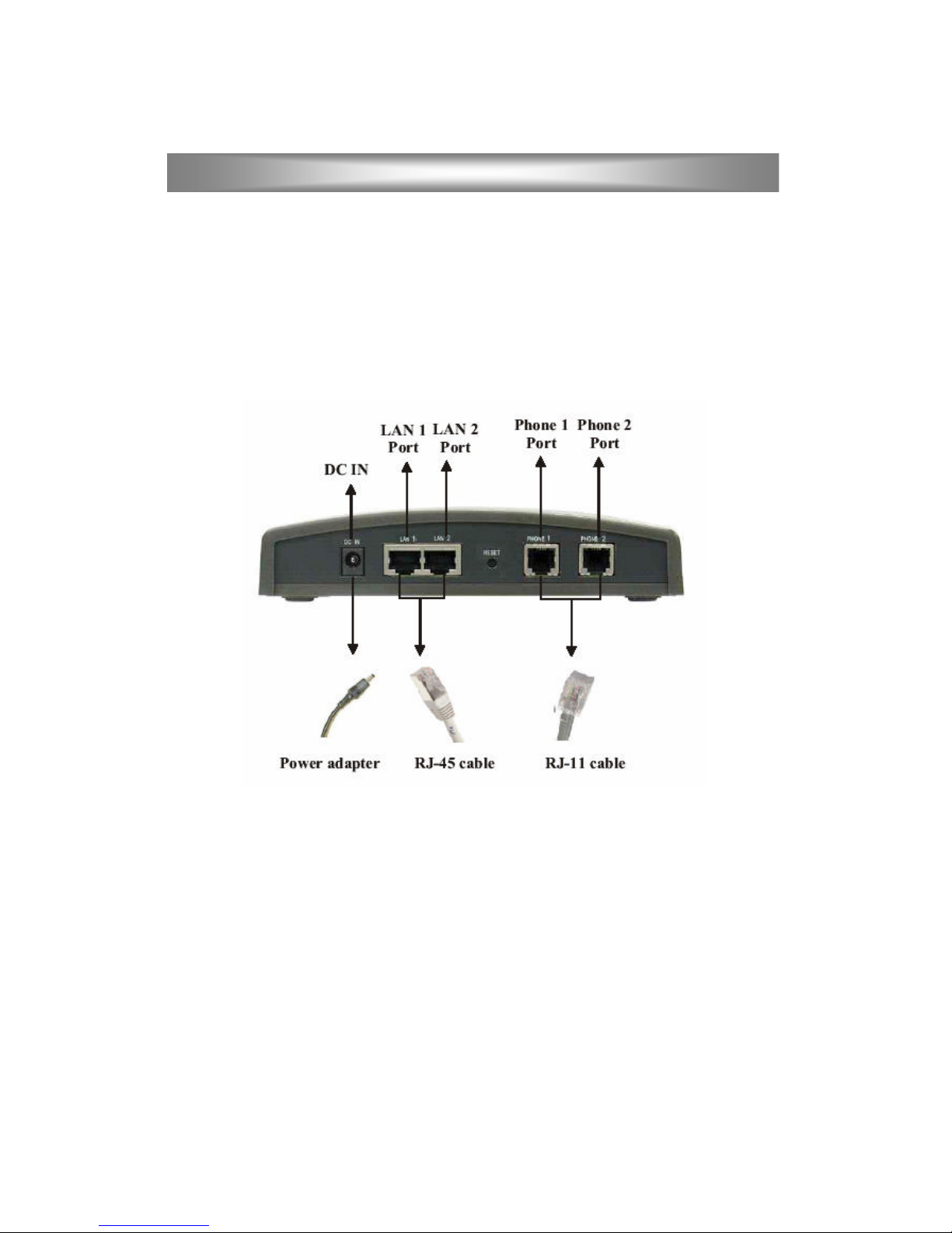
BVA 8052 Series (8052S and 8052D/DL)
LAN: connect to a router or a device accessing the Internet. (eg. an ADSL or cable
modem)
Note: 8052S has one LAN port but 8052D/DL has two LAN ports functioning
as an Ethernet Switch. You can use either one.
PHONE1: connect to a telephone set.(1 st phone line)
PHONE2: connect to a telephone set.(2 nd phone line)- not available in 8052DL.
DC IN: plug in the included power adapter.
BVA 8053 Series (8053R and 8053RL)
WAN: connect to a device accessing the Internet. (eg. an ADSL or cable modem)
LAN: connect to a PC's Ethernet port.
LINE: connect to a telephone line wall socket (PSTN). (8053R only)
PHONE: connect to a telephone set.
DC IN: plug in the included power adapter.
Installation and Configuration
Page 3
2
Back panel for 8052D
Installation and Configuration
Page 4

3
Powering on the Device
Each time you turn on the device (including the very first time), you should leave it alone
for at least 5 minutes. During this period, the configuration information maybe be
obtained from your service provider and some critical functions like firmware updating
can be performed by the device . Turning off the device during this period may cause the
device to malfunction and require a factory service.
Restoring Factory Defaults
1. Unplug the power.
2. Connect the telephone to PHONE 1 PORT.
3. Lift the handset off the telephone (off-hook).
4. Use a pin to push the RESET button at the back of the device. Hold it while you plug
the power back to the device. The Power LED should be flashing rapidly.
5. Continue to hold the RESET button until you see four of the six LEDs flashing
several times in pairs. Release the pin and wait until all LEDs stop flashing. This
whole process may take up to 10 seconds.
6. Put the handset back on the telephone (on-hook).
7. The factory defaults should have been restored.
Changing Settings Using a Browser
If this device is provided to you by your telephony service provider, it may have already
been setup to work properly with their service. Changing any settings may cause the
device to stop functioning. Please contact your service provider for details.
This device, in its factory default, has been configured to work with a DHCP server. To
change this or to make any other modifications to the default configurations, you can use
a web browser from your PC. First connect the device to a DHCP- enabled router with
which your PC also shares. Identify the IP address assigned to this device by examining
the router's DHCP table.
Your service provider may also provide different tools or methods, please check their
web sites for further information. Use the identified IP address in the browser to access
the configuration pages.
Installation and Configuration
Page 5

4
Changing Settings Using a Telephone Set (B VA 8051 and BVA 8052 Series only)
Follow the steps in "Restoring Factory Defaults" to reset the device. In step #3, when you
see the Power LED flashing rapidly, immediately release the RESET button. Your
telephone handset should now be beeping. You can perform the following functions
using the buttons on the keypad.
A) Set Fixed IP Address
1. Enter the IP address. Press * for .(dot) and # to terminate this entry.
For example: 215*202*102*56# for 215.202.102.56
2. Enter the Netmask. Press # to terminate this entry.
3. Enter the Gateway IP. Press # to terminate this entry.
4. Enter the DNS server IP. Press # to terminate this entry.
On pressing the # key for each step, the pitch of the tone will drop. After entering the
DNS server IP, there will be a confirmation tone. Hang up the phone to reboot.
B) Set DHCP
Enter 0#. There will be a confirmation tone. Hang up the phone to reboot.
C) Enter the Downloader mode
Enter 1#. There will be a confirmation tone. Hang up the phone to reboot. After rebooting,
the device will be in the Downloader mode.
When the Application firmware is corrupted and the browser can no longer access the
device, you can use this method to reset the device into the Downloader mode, connect to
a browser again, and reload the Application firmware.
Installation and Configuration
Page 6

5
Configuring the Auto Provisioning System (APS)
The Auto Provisioning System requires the support of your telephony service provider.
You also need specific APS parameters. Please check with your service provider for
details.
To configure the Auto Provisioning System in the device, you need to use a browser.
Please see the section called "Changing Settings Using a Browser".
1. Go to the System menu. Select the APS tab.
2. Under the Automatic Configuration entry, select Standard.
3. Under the APS Server Address entry, enter the FQDN (Fully Qualified Domain Name)
or the IP address of the APS server.
4. Under the APS Port entry, enter 69 or the number provided by your service provider.
5. Click the Save APS Settings button.
6. Reset the device by going to the Reset menu, select Reset and execute Main
Application, and click the Reset button.
The device will reset itself, retrieve the configuration parameters from your service
provider, then reset itself again. This process may take up to 5 minutes. Please see the
section called "Powering on the Device".
Upgrading the firmware
New firmware may be available from your service provider from time to time. If you
decide to upgrade the system yourself, please follow the steps below.
1. Download the correct version of the firmware file into your PC.
Remember where you put it.
2. Go to the Download menu in your device. Under the HTTP Download method, enter
the location and filename of the file you downloaded in the above step.
3. Click the Start HTTP Download button. This will start the upgrade process.
4. When firmware upgrade is completed, select " Restart Main Application".
5. Verify if the upgrade is successful by checking the firmware version displayed at the
Home page of the device.
Installation and Configuration
Page 7

6
Switching between IP and PSTN Calls (8051S and 8053R only)
If you have an 8051S or an 8053R and connected a telephone line (PSTN) to the LINE
port, you can use the same telephone set to make either IP or PSTN calls. When you pick
up the telephone handset, the default type determines whether your call will be an IP call
or a PSTN call. You use a switching key to switch between the two types of call.
You can change the default type and the switching key by following the steps below.
1. Go to the SIP menu in your device. Select the PSTN tab.
2. Select Make SIP calls by default to make SIP calls as the default type.
3. Select Make PSTN calls by default to make PSTN calls as the default type.
4. Under the Switching key entry, select the key you want to use as the switching key.
You can only make one type of call at a time. However, your pho ne will ring when there
is an incoming call on either the IP line or the PSTN line.
Installation and Configuration
Page 8

7
Using the Advanced Calling Features
Advanced calling features depend on your service provider. Please contact your service
provider before using.
Note: F denotes the Flash key on your telephone set. If your phone does not have a Flash
key, you can simulate a flash by pressing and releasing quickly the handset hook switch.
3-way Conferencing
A calls B.
A presses F7 to get dial-tone.
A calls C.
When C answers, A-B-C are in a conference.
Call Waiting
A calls B.
C calls A. A hears call-waiting beeps.
A presses F* to alternate between C and B.
Call Hold
A calls B.
A presses F1 to put B on hold. A gets dial-tone.
A can call C to have another conversation.
A presses F* to retrieve B from hold.
Call Transfer
B calls A.
A answers, presses F4. A gets dial-tone.
A calls C. B gets transferred to C.
Call Forward
Turning on Forwarding:
A presses *2 + (phone number for C).
B calls A. B gets forwarded to C.
Turning off Forwarding:
A presses *3.
Trouble-Shooting
You can visit the web site of your service provider to locate a trouble-shooting guide or a
FAQ.
Installation and Configuration
Page 9

8
LED indicators
BVA8051 Series
Label POWER LINK ACTIVITY
LINE PHONE MESSAGE
Behavior
ON:power on
and IP
address
acquired
OFF:power off
SlowBlinking:
Acquiring IP
address
ON:LAN is
connected
OFF:LAN is
not
connected
Blinking:
Network
traffic on
LAN
ON:PSTN
line is
off-hook
(In use)
OFF:PSTN
line is
on-hook
Fast
Blinking:
Incoming
call from
PSTN
(8051S)
ON:IP line
is off-hook
(In use)
OFF: IP
line is on
hook
Slow
Blinking:
Registering
to service
failed
Fast
Blinking:
Incoming
call from
IP
ON:Message
waiting
OFF:No
message
waiting
(Service
dependent)
BVA8052 Series
Label POWER LINK ACTIVITY PHONE1 PHONE2 STATUS
Behavior
ON:power on
OFF:power
off
ON:LAN is
connected
OFF:LAN is
not
connected
Blinking:
Network
traffic on
LAN
ON:IP line
is off-hook
(In use)
OFF:IP line
is on-hook
Slow
Blinking:
Registering
to service
failed
Fast
Blinking:
Incoming
call from
IP
ON:IP line
is off-hook
(In use)
OFF:IP line
is on-hook
Slow
Blinking:
Registering
to service
failed
Fast
Blinking:
Incoming
call from
IP
ON:IP
address
acquired
Slow
Blinking:
Acquiring
IP address
LED Indicators
Page 10

9
BVA8053 Ser ies
Label POWER LAN WAN LINE PHONE STATUS
Behavior
ON:power on
OFF:power
off
ON:LAN is
connected
OFF:LAN is
not
connected
Blinking:
Network
traffic on
LAN
ON:WAN is
connected
OFF: WAN
Is not
connected
Blinking:
Network
traffic on
WAN
ON:PSTN
line is
Off-hook
(In use)
OFF:PSTN
line is
On-hook
(In use)
Fast
Blinking:
Incoming
call from
PSTN
(8053R)
ON:IP line
is Off-hook
(In use)
OFF:IP line
is On-hook
(In use)
Slow
Blinking:
Registering
to service
failed
Fast
Blinking:
Incoming
call from
IP
ON:WAN IP
address
acquired
Slow
Blinking:
Acquiring
WAN IP
address
LED Indicators
Page 11

10
This device complies with Part 15 of the FCC Rules. Operation is subject to the following
two conditions:
1. This device may not cause harmful interference.
2. This device must accept any interference received, including interference that may
cause undesired operation.
This equipment has been tested and found to comply with the limits for a Class B digital
device pursuant to Part 15 of FCC Rules. These limits are desig ned to provide reasonable
protection against harmful interference in a residential installation. This equipment
generates, uses and can radiate radio frequency energy and, if not installed and used in
accordance with the instructions,may cause harmful interference to radio communications.
However, there is no guarantee that interference will not occur in a particular installation.
If this equipment does cause harmful interference to radio or television reception, which
can be determined by turning the equip ment off and on, the user is encouraged to try to
correct the interference by one or more of the following measures:
1. Reorient or relocate the receiving antenna.
2. Increase the separation between the equipment and receiver.
3. Connect the equipment into an outlet on a circuit different from that to which the
receiver is connected.
4. Consult the dealer or an experienced radio/TV technician for help.
5. Shielded interface cables must be used in order to comply with emission limits.
Changes or modifications not expressly approved by the party responsible for
compliance could void the user's authority to operate the equipment.
FCC Statement
 Loading...