

Page 1
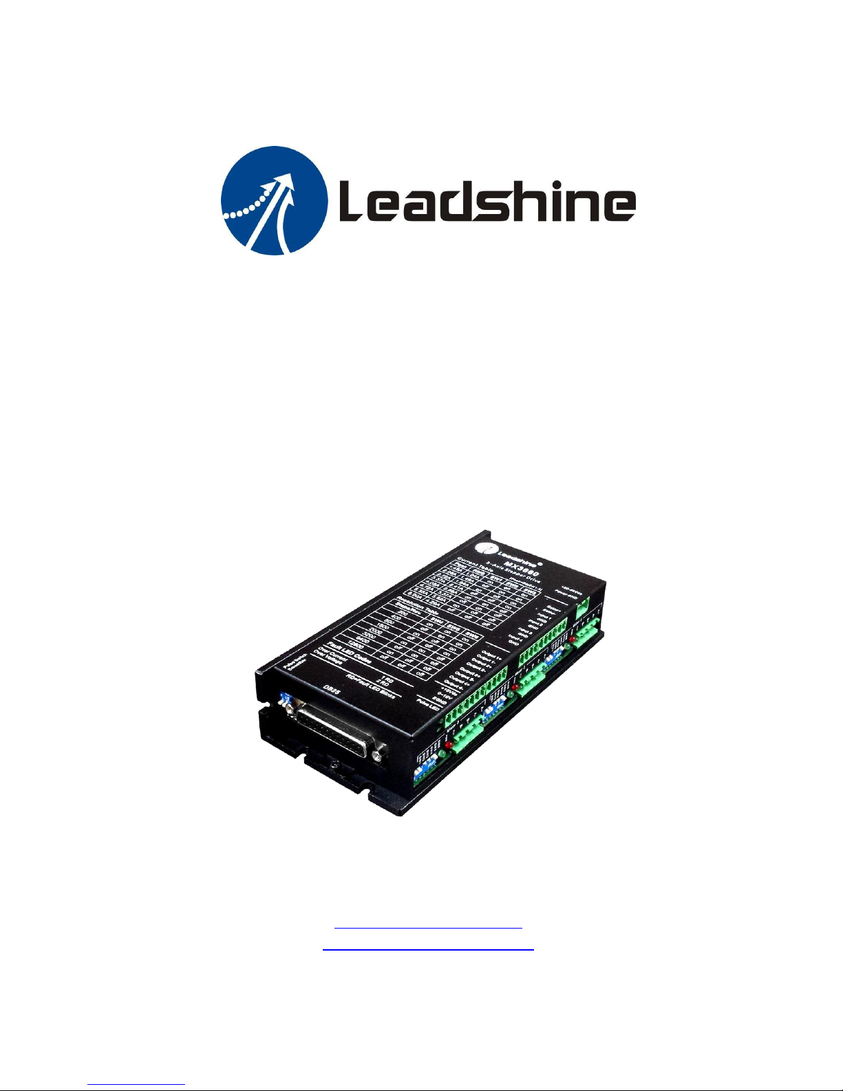
Hardware Installation Manual
MX3660
3-Axis Stepper Drive with Breakout Board & I/O’s
Version 1.2
3 / 2015
http://www.leadshine.com
http://www.leadshineusa.com
© 2015 Leadshine Technology Co., Ltd.
Page 2

Revision
Date
Description of Release
1.0
11/2013
Initial Release
1.1
1.2
12/2013
03/2015
Update for connection diagram and digital output description
Update output current tables ,description for power input and analog
output
Hardware Manual for Leashine MX3660 3-Axis Stepper Drive with Breakout Board & I/O’s ii
Notice
Read this manual carefully and the MX3660 datasheet before any assembling and using. Incorrect handling of
products in this manual can result in injury and damage to persons and machinery. Strictly adhere to the technical
information regarding installation requirements.
This manual is not for use or disclosure outside of Leadshine except under permission. All rights are reserved. No
part of this manual shall be reproduced, stored in retrieval form, or transmitted by any means, electronic,
mechanical, photocopying, recording, or otherwise without approval from Leadshine. While every precaution has
been taken in the preparation of the book, Leadshine assumes no responsibility for errors or omissions. Neither is
any liability assumed for damages resulting from the use of the information contained herein.
This document is proprietary information of Leadshine that is furnished for customer use ONLY. Information in this
document is subject to change without notice and does not represent a commitment on the part of Leadshine.
Therefore, information contained in this manual may be updated from time-to-time due to product improvements,
etc., and may not conform in every respect to former issues.
Record of Revisions
Page 3

Hardware Manual for Leashine MX3660 3-Axis Stepper Drive with Breakout Board & I/O’s iii
Contents
1. INTRODUCTION ........................................................................................................................ 4
2. FEATURES ................................................................................................................................. 4
3. APPLICATIONS .......................................................................................................................... 4
4. BLOCK DIAGRAM ...................................................................................................................... 5
5. DIMENSIONS ............................................................................................................................ 6
6. GET STARTED ............................................................................................................................ 6
7. CONNECTING A POWER SUPPLY ................................................................................................ 7
8. CONNECTING STEPPER MOTORS ............................................................................................. 7
8.1. CONNECTING A 4-LEAD STEPPER MOTOR ............................................................................................. 7
8.2. CONNECTING A 6-LEAD STEPPER MOTOR ............................................................................................. 8
8.2.1. CONNECTING A 6-LEAD STEPPER MOTOR IN SERIES CONNECTION ................................................... 8
8.2.2. CONNECTING A 6-LEAD STEPPER MOTOR IN SERIES CONNECTION ................................................... 8
8.3. CONNECTING A 8-LEAD STEPPER MOTOR ............................................................................................. 9
8.3.1. CONNECTING A 8-LEAD STEPPER MOTOR IN SERIES CONNECTION ................................................... 9
8.3.2. CONNECTING A 8-LEAD STEPPER MOTOR IN PARALLEL CONNECTION............................................... 9
9. CONNECTING AN E-STOP SWITCH OR SHORTING THE CONNECTION ....................................... 10
10. ENABLING / DISABLING CHARGE PUMP ................................................................................ 11
11. SETTING THE “SMOOTHER” SWITCH ...................................................................................... 11
12. CONFIGURING OUTPUT CURRENT AND MICRO STEP ............................................................. 12
12.1. CONFIGURING THE OUTPUT CURRENT ............................................................................................. 12
12.2. CONFIGURING THE OUTPUT CURRENT ............................................................................................. 13
13. CONNECTING THE DB25 CONNECTOR .................................................................................... 13
13.1. CONNECTING THE DB25 STEP & DIRECTION PINS .............................................................................. 13
13.2. CONNECTING THE DB25 FAULT OUTPUT PIN ..................................................................................... 14
13.3. CONNECTING THE DB25 CHARGE PUMP PIN ..................................................................................... 14
13.4. CONNECTING THE PWM PIN ............................................................................................................ 14
14. OPTIONAL CONNECTIONS FOR INPUTS/OUTPUTS ................................................................. 16
14.1. CONNECTING THE DIGITAL INPUTS .................................................................................................. 16
14.2. CONNECTING THE DIGITAL OUTPUTS ............................................................................................... 16
14.3. CONNECTING THE ANALOG OUTPUT ................................................................................................ 16
APPENDIX A: MX3660 CONNECTION DIAGRAM ........................................................................... 19
APPENDIX B: DB25 CONNECTOR PINOUT .................................................................................... 20
APPENDIX C: DIGITAL INPUTS ..................................................................................................... 22
APPENDIX D: DIGITAL OUTPUTS ................................................................................................. 23
APPENDIX E: OPTO-ISOLATED ANALOG OUTPUT ......................................................................... 23
APPENDIX F: STEPPER DRIVE MODULE REPLACEMENT ................................................................ 24
APPENDIX G: WARRANTY INFORMATION .................................................................................... 24
APPENDIX H: TROUBLE SHOOTING ............................................................................................. 24
CONTACT US ................................................................................................................................. 25
Page 4
Hardware installation manual of the multi-axis drive MX3660
!
Warning
The MX3660 can also be used to power 4-phase (0.9°) stepper motors. But in this case,
there will be 400 full steps needed for each revolution. You need to make sure that the
settings in your controller (motion controller, PLC, CNC control system…) are properly
configured to reflect this requirement.
1. Introduction
Thank you for choosing the Leadshine MX3660, a high performance 3-axis stepper drive with built-in breakout
board and I/O’s based on the latest DSP technology. The MX3660 is specially designed for EASY and RAPID control of
up to three 2-phase (1.8°) stepper motors in frame sizes NEMA 17, 23, 24, and 34. It operates under 20-60 VDC
supply voltage and can output up to 6.0A current (peak of sinusoidal) per axis. The MX3660 takes step & direction
control and is easy to implement for OEM applications.
2. Features
Power up to 3 stepper motors of NEMA 17, 23, 24, or 34
Sophisticated stepper motor control based on latest DSP technology
Built-in breakout board and I/O’s
Step & direction Control
200 KHz maximum frequency for each axis
20 - 60 VDC supply voltage
1.41 - 6.0A (1.45 - 6.0A) output current per axis
8 micro step settings: 1, 1/2, 1/4, 1/8, 1/10, 1/16, 1/32, 1/64
8 output current settings: 1.41, 2.12, 2.83, 3.54, 3.96, 4.24, 4.95, 6.0 A (version1.0b, it’s the latest and
default version for future), corresponding RMS current settings: 1.0, 1.5, 2.0, 2.5, 2.8, 3.0, 3.5, 4.25A
8 output current settings: 1.45, 2.08, 2.72, 3.37, 4.05, 4.72, 5.35, 6.0 A (for previous version1.0a)
Damping and anti resonance
Allowing individual output current & micro step configurations for each axis
Input pulse smoothing to improve performance of movement jittering
Extra low motor heating & noise
Extra smooth motor movement
Simple micro step & output current configuration via DIP switches
Fault output
Compact size and easy setup
50% automatic idle current reduction
3. Applications
The MX3660 3-axis stepper drive can be easily and rapidly implemented in stepper control systems for applications
such as CNC routers / engravers, CNC mills, CNC cutters, laser cutters / markers / engravers, CNC welders, CNC
water jets, X-Y tables, lathes, dispensing machines, medical equipment, scientific instruments…
Its unique design with built-in breakout board and I/O’s fits seamlessly in many applications powered by many
popular CNC control systems such as Mach3, Mach4, EMC, WinCNC, etc.
Leadshine Technology Co., Ltd Leadshine America, Inc. Page 4/25
11/F, Block A3, iPark, No.1001 Xueyuan Blvd, Nanshan District, Shenzhen, China 25 Mauchly, Suite 318, Irvine, CA 92618, USA
Tel: 86-755-26409254 Fax: 86-755-26402718 Tel: 1-949-608-7270 Fax: 1-949-608-7298
Web: www.leadshine.com Email: [email protected] Web: www.leadshine.com Email: [email protected]
Page 5
Hardware installation manual of the multi-axis drive MX3660
MX3660
CNC Machines / Devices
Inputs
Controller
Or
Or
Motion
Controller
PC-Based
Control System
(Mach3, WinCNC
EMC…)
Breakout
Board
Drive 1
I/O
Ext. Device
(e.g. Limit Switches)
Ext. Device
(e.g. VFD)
Ext. Device
(e.g. Coolant)
PWM
Stepper Motor X
Stepper Motor Y
Stepper Motor Z
Output1
0-10V
Outputs
Ext. Device
(E.g. Spindle Motor)
4-pin Screw
Terminal
I/O’s
Input
DB25
Power
Module
Power Supply
6-bit DIP
Drive 2
4-pin Screw
Terminal
6-bit DIP
Drive 3
4-pin Screw
Terminal
6-bit DIP
Charge
Pump
Digital
Smoother
Switch
PLC
ESTOP
DSP
DSP
DSP
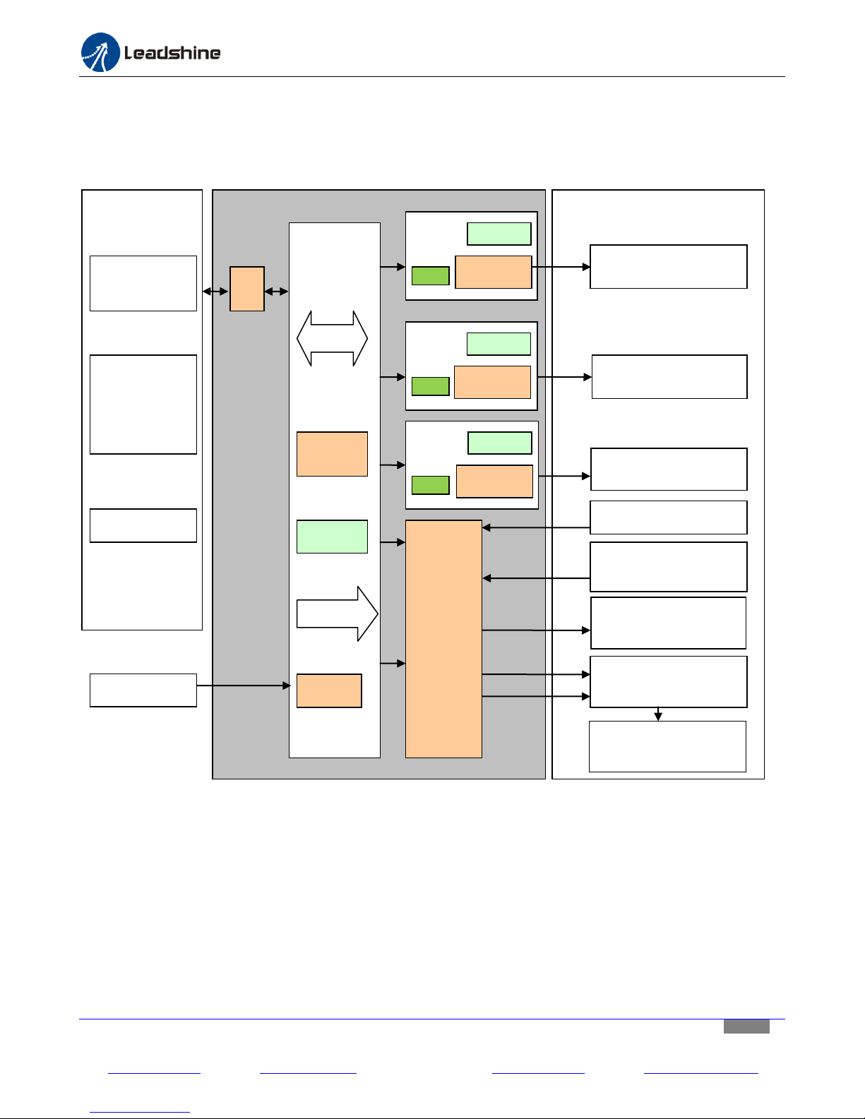
4. Block Diagram
The following diagram shows MX3660 main internal components and how it interfaces with other components in
the motion control system of your machine/device.
Leadshine Technology Co., Ltd Leadshine America, Inc. Page 5/25
11/F, Block A3, iPark, No.1001 Xueyuan Blvd, Nanshan District, Shenzhen, China 25 Mauchly, Suite 318, Irvine, CA 92618, USA
Tel: 86-755-26409254 Fax: 86-755-26402718 Tel: 1-949-608-7270 Fax: 1-949-608-7298
Web: www.leadshine.com Email: [email protected] Web: www.leadshine.com Email: [email protected]
Figure 1 MX3660 Block diagram
Page 6
5. Dimensions
162±0.5
169±1.5
19.5±0.3
54.5±0.3
77.5±1.5
5
162±0.5
16±0.2
37±1.5
5
3.5
3.5
CN1: DB25 Connector
DP3: Z-Axis DIP switch
CN5: Z-Axis Motor Connector
DIP2: Y-Axis DIP switch
DP1: X-Axis DIP switch
CN3: X-Axis Motor Connector
CN4: Y-Axis Motor Connector
CN8: Analog Output
CN7: Digital Outputs
CN6: Digital Inputs
CN2: Power Connector
DP4: Pulse Switch &
Smoother switch
Hardware installation manual of the multi-axis drive MX3660
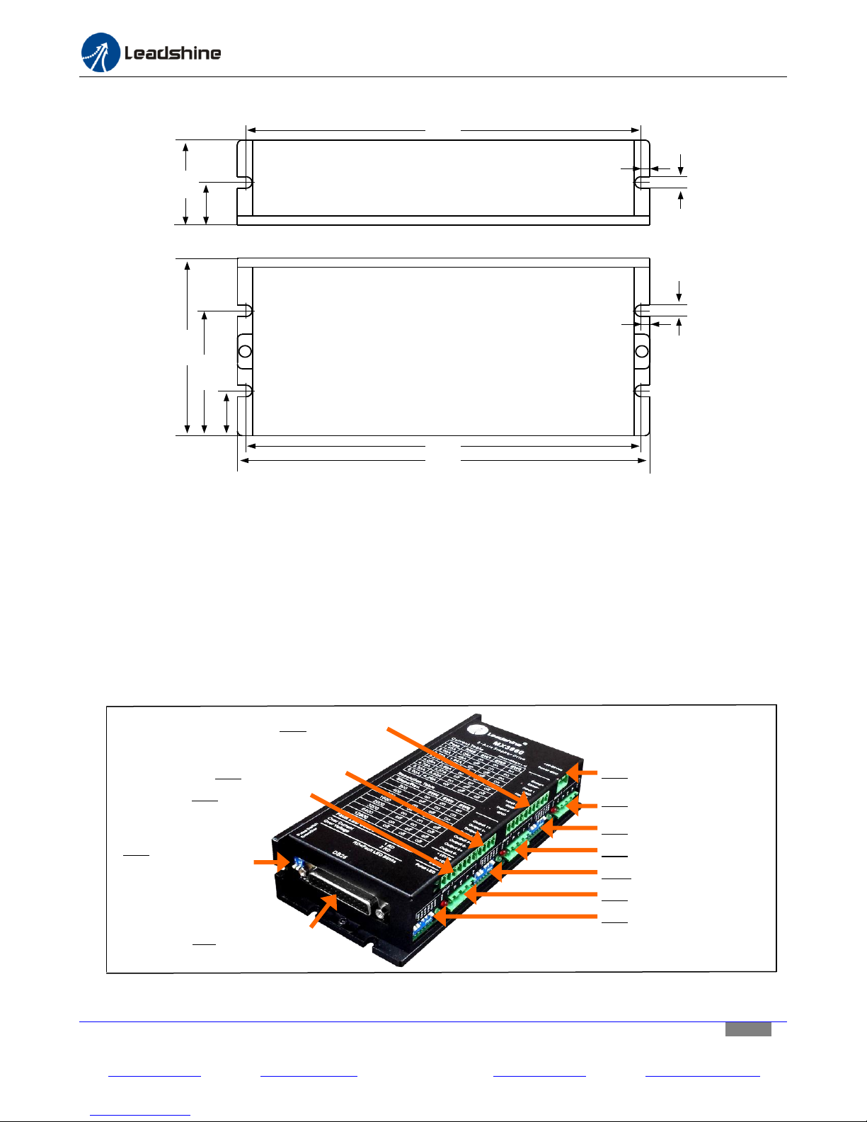
Figure 2 MX3660 dimensions
6. Get Started
Before you start hardware connection, refer to the following MX3660 layout diagram (figure 3) for connector/DIP
switch location. Read the MX3660 datasheet for each connector explanation. Then, get the following prepared:
A 24-54 VDC power supply.
Up to 3 stepper motors depending on how many axes that MX3660 will power in your application.
A source of step signals, such as a motion controller, PLC, or a PC-based control system (Mach3/4 , EMC, etc.).
A small flat blade screw driver for tightening the screw connectors of the MX3660.
Whatever optional external devices needed to be controlled through the built-in outputs and inputs.
Leadshine Technology Co., Ltd Leadshine America, Inc. Page 6/25
11/F, Block A3, iPark, No.1001 Xueyuan Blvd, Nanshan District, Shenzhen, China 25 Mauchly, Suite 318, Irvine, CA 92618, USA
Tel: 86-755-26409254 Fax: 86-755-26402718 Tel: 1-949-608-7270 Fax: 1-949-608-7298
Web: www.leadshine.com Email: [email protected] Web: www.leadshine.com Email: [email protected]
Figure 3 MX3660 layout
Page 7
Hardware installation manual of the multi-axis drive MX3660
!
Warning
(1) Never power on the power supply before finishing all the connections and
configurations.
(2) Make sure the two power supply leads,
﹢&﹣
, are correctly connected to the MX3660
power connector. Wrong connection will destroy the MX3660 and void its warranty.
(3) Connecting a power supply with output voltage of 60VDC or up could damage the
MX3660, and void its warranty.
+20-60VDC
Power GND
DC Power Supply
(20-54VDC)
MX3660
+
-
7. Connecting a Power Supply
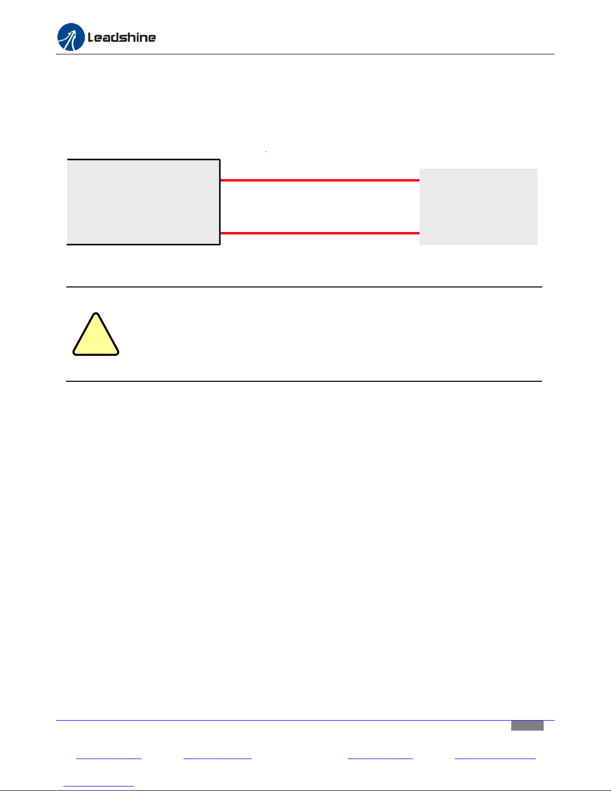
The power supply connector is located at the upper left side of MX3660 (“CN2” in Figure 3). The power supply of the
MX3660 can be connected as illustrated in Figure 4. Although MX3660’s working voltage is 20-60 VDC, we suggest
the use of a 20-54 VDC power supply to leave room for back EMF voltage charge back during motor deceleration.
Figure 4 Power supply connections
8. Connecting Stepper Motors
There are 3 stepper drive modules for the MX3660 to allow connections of up to three 2-phase stepper motors.
Because of the wide output current range from 1.41 to 6.0A for each stepper drive module, the MX3660 can drive
various stepper motors in frame sizes NEMA 17, 23, 24, and 34. You can find the 3 stepper drive modules locate at
CN3, CN4, and CN5 on Figure 3. These stepper motors can be 4-lead, 6-lead, or 8-lead stepper motors.
To get the maximum torque from a stepper motor, the output current required from a stepper drive equals to the
motor phase current multiplied by 1.4. Higher output current from a stepper drive module will result the stepper
motor torque; but that also increase the motor heating. Therefore, it is recommended to set “just-enough” output
put current to get the needed torque, and as less motor heating as possible.
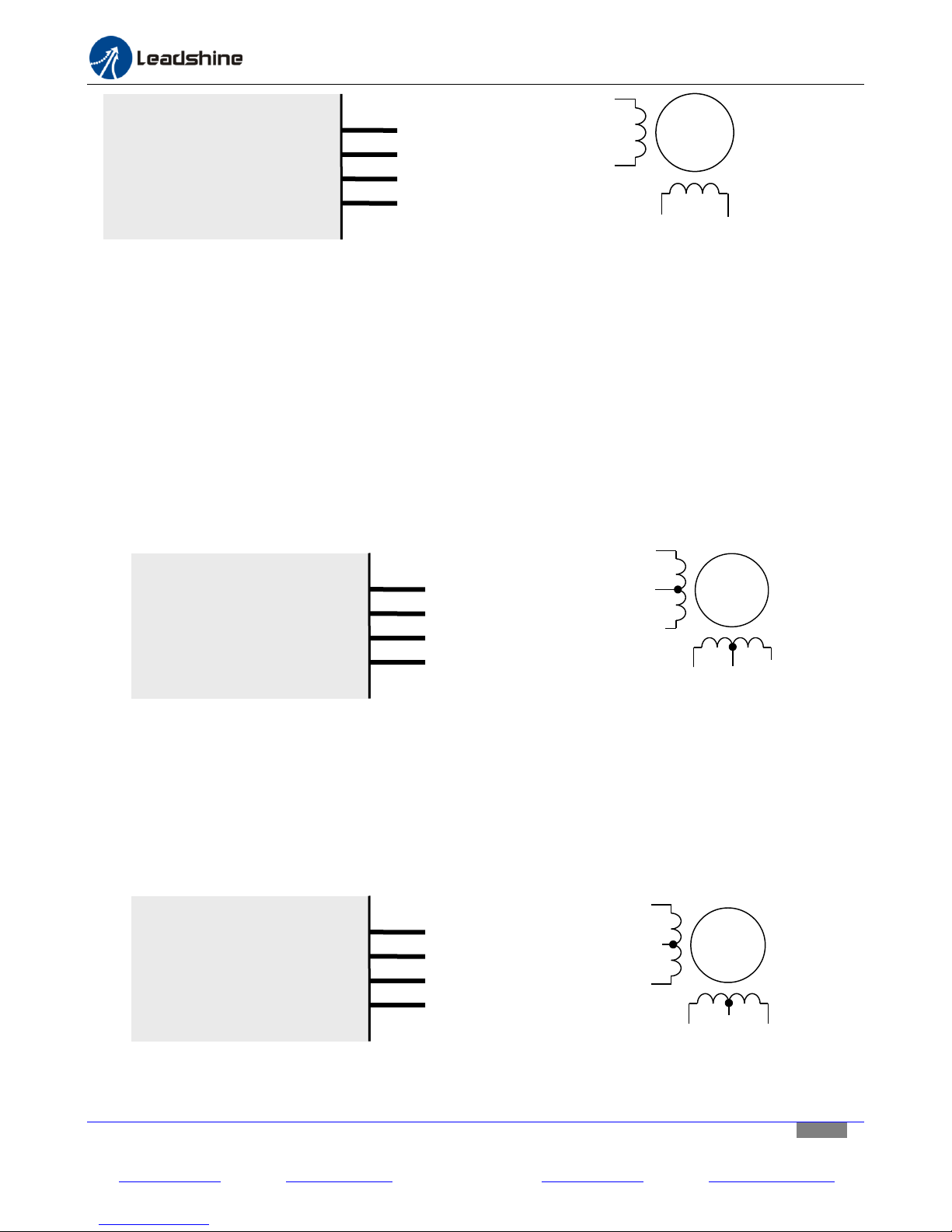
8.1. Connecting a 4-Lead Stepper Motor
A 4 lead motor is the easiest to connect, and its speed-torque performance depends on its motor inductance.
Refer to the wiring diagram of your stepper motor, and connect its wires to the motor connector to one of the
MX3660 stepper drive module. Refer to Figure 5 on next page.
Leadshine Technology Co., Ltd Leadshine America, Inc. Page 7/25
11/F, Block A3, iPark, No.1001 Xueyuan Blvd, Nanshan District, Shenzhen, China 25 Mauchly, Suite 318, Irvine, CA 92618, USA
Tel: 86-755-26409254 Fax: 86-755-26402718 Tel: 1-949-608-7270 Fax: 1-949-608-7298
Web: www.leadshine.com Email: [email protected] Web: www.leadshine.com Email: [email protected]
Page 8
Hardware installation manual of the multi-axis drive MX3660
A+
A-
B+
B-
MX3660
A+
A-
B+
B-
6-lead Stepper Motor
6 Leads
A+
A-
B+
B-
NC
NC
A+
A-
B+
B-
MX3660
A+
A-
B+
B-
6-lead Stepper Motor
6 Leads
A+
A-
B+
B-
NC
NC
A+
A-
B+
B-
MX3660
A+
A-
B+
B-
4-lead Stepper Motor
4 Leads
A+
A-
B+
B-
Figure 5 Connecting a 4-lead stepper motor
8.2. Connecting a 6-Lead Stepper Motor
The MX3660 can drive 6-lead stepper motors in either half coil connection or full coil connection. Before the
connection, please read the datasheet of your stepper motor.
8.2.1. Connecting a 6-Lead Stepper Motor in series connection
This configuration is also referred to as half chopper. When connecting a 6-lead stepper motor, the half coil
configuration uses 50% of the motor phase windings. This results in lower inductance, and hence lower torque
output at low-speed movements. Like the parallel connection of an 8 lead motor, this connection is commonly
used in applications requiring better high-speed torque performance. Refer to Figure 6 for the connection.
Figure 6 Connecting a 6-lead stepper motor in half-coil
8.2.2. Connecting a 6-Lead Stepper Motor in series connection
This configuration is also referred to as full copper. The full coil connection for a six lead motor is commonly
used in applications requiring for higher torque performance at lower-speed movements. Refer to Figure 7 for
the connection.
Leadshine Technology Co., Ltd Leadshine America, Inc. Page 8/25
11/F, Block A3, iPark, No.1001 Xueyuan Blvd, Nanshan District, Shenzhen, China 25 Mauchly, Suite 318, Irvine, CA 92618, USA
Tel: 86-755-26409254 Fax: 86-755-26402718 Tel: 1-949-608-7270 Fax: 1-949-608-7298
Web: www.leadshine.com Email: [email protected] Web: www.leadshine.com Email: [email protected]
Figure 7 Connecting a 6-lead stepper motor in full coil
Page 9
Hardware installation manual of the multi-axis drive MX3660
A+
A-
B+
B-
MX3660
A+
A-
B+
B-
8-lead Stepper Motor
8 Leads
A+
A-
B+
B-
8.3. Connecting a 8-Lead Stepper Motor
The MX3660 can drive an 8-lead stepper motor in either series connection or parallel connection. Before the
connection, please read the datasheet of your stepper motor.
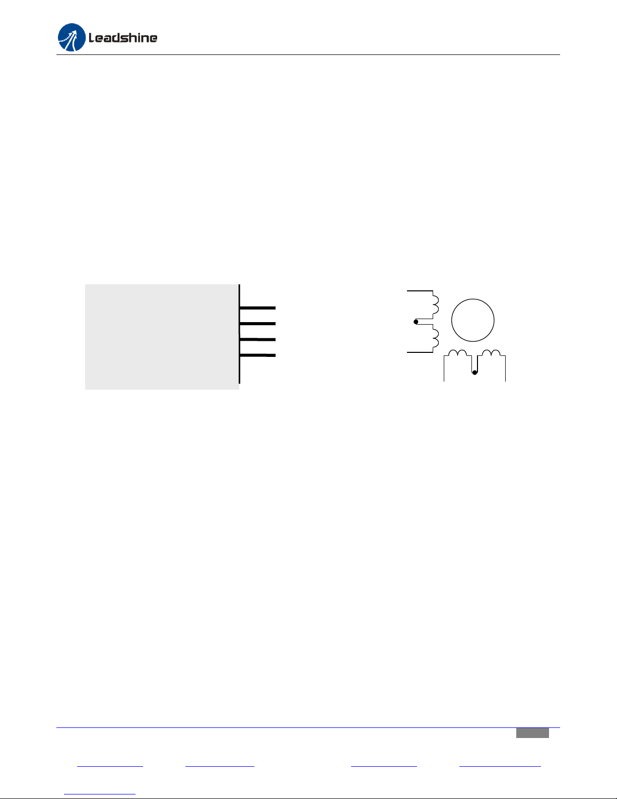
8.3.1. Connecting a 8-Lead Stepper Motor in series connection
Refer to the wiring diagram of your stepper motor datasheet. Figure 8 illustrates how to connect an 8-lead
stepper motor to the MX3660 in series connection.
An 8-lead stepper motor in series connection requires less current, so the motor coils can be charged quicker
and achieves peak output torque faster than the same motor connected in parallel connection. This makes
series connection preferable for applications that require higher torque at lower speed. But on the other side,
because of its higher inductance, 8-lead stepper motor in series connection generates more motor heating and
its higher speed torque performance is not good as a parallel connected stepper motor. It is recommended for
not setting drive current no more than 70% of its rated current to prevent too much heating for a series
connected 8-lead stepper motor, but what current to set is application dependent and at a user’s choice.
Figure 8 Connecting an 8-lead stepper motor in series connection
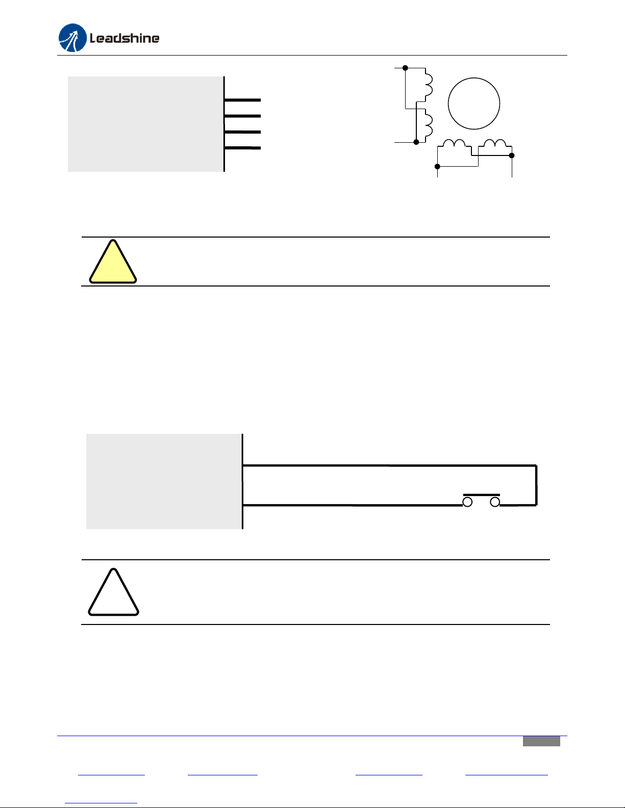
8.3.2. Connecting a 8-Lead Stepper Motor in Parallel Connection
Refer to the wiring diagram of your stepper motor datasheet. Figure 9 illustrates how to connect an 8-lead
stepper motor to the MX3660 in parallel connection.
Due to the lower inductance for an 8-lead stepper motor in parallel connection, its high speed torque drops
slower (“better high-speed torque”) than in series connection during higher speed motor rotation. This makes
parallel connection preferred for applications runs in high speeds constantly such as CNC Routers. Due to the
parallel connected stepper motor will draw more current, thus it also has high requirements for the powering
stepper drive. Fortunately, the maximum 6.0A output for each of three stepper drive module will allow the
MX3660 to drive stepper motors up to NEMA 34 in parallel connection.
Theoretically, to get the maximum torque of a parallel connected 8-lead stepper motor, you should multiply the
phase current by 1.4. But it is suggested to set a “just enough” lower value to prevent too much heating from
your stepper motor.
Leadshine Technology Co., Ltd Leadshine America, Inc. Page 9/25
11/F, Block A3, iPark, No.1001 Xueyuan Blvd, Nanshan District, Shenzhen, China 25 Mauchly, Suite 318, Irvine, CA 92618, USA
Tel: 86-755-26409254 Fax: 86-755-26402718 Tel: 1-949-608-7270 Fax: 1-949-608-7298
Web: www.leadshine.com Email: [email protected] Web: www.leadshine.com Email: [email protected]
Page 10
Hardware installation manual of the multi-axis drive MX3660
!
Warning
Never connect or disconnect a stepper motor while the power is on.
!
Notice
Without the a E-STOP switch connected, or short circuit between Estop+ and Estoppins, the red LED lights of the 3 stepper drive modules will blink 3 times periodically
when MX3660 is powered on
Estop+
Estop-
MX3660
E-Stop Switch
Normal close
A+
A-
B+
B-
MX3660
A+
A-
B+
B-
8-lead Stepper Motor
8 Leads
A+
A-
B+ B-
Figure 9 Connecting an 8-lead stepper motor in parallel connection
9. Connecting an E-Stop Switch or Shorting the Connection
The E-Stop connection is required. The E-Stop connector is located next to the power connector (Figure 3). By
default, the MX3660’s activation requires an emergency stop switch connected, or having the two connection
pins, “ESTOP+” and “ESTOP-“, shorted.
Refer to Figure 10 for how to connect an” E-Stop switch. To short the E-Stop connection, just connect a signal
wire between the “ESTOP+” and “ESTOP –” pins.
Figure 10 E-stop switch connections
Leadshine Technology Co., Ltd Leadshine America, Inc. Page 10/25
11/F, Block A3, iPark, No.1001 Xueyuan Blvd, Nanshan District, Shenzhen, China 25 Mauchly, Suite 318, Irvine, CA 92618, USA
Tel: 86-755-26409254 Fax: 86-755-26402718 Tel: 1-949-608-7270 Fax: 1-949-608-7298
Web: www.leadshine.com Email: [email protected] Web: www.leadshine.com Email: [email protected]
Page 11
Hardware installation manual of the multi-axis drive MX3660
!
Caution
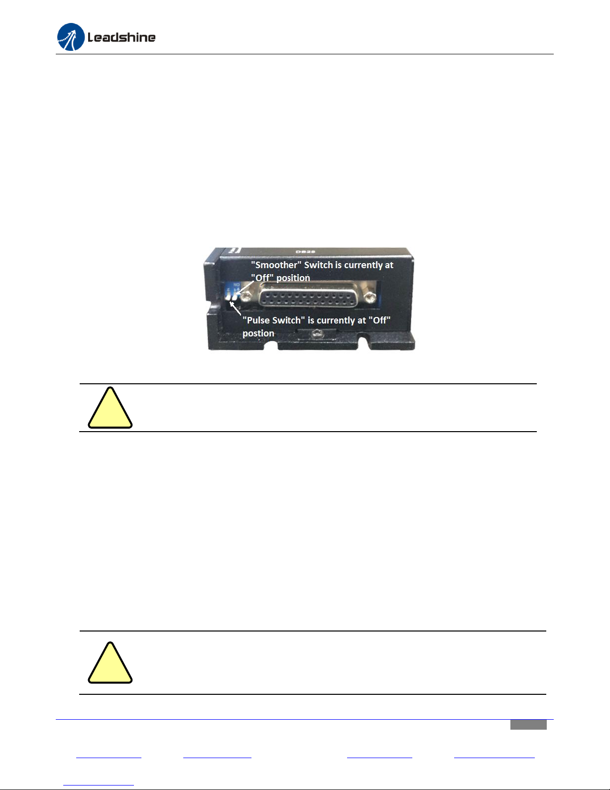
The ON/OFF direction for the “Pulse Switch” is different from the ON/Off direction
of the DIP switch in a stepper drive module, which is used to configure the output
current and micro step by a stepper drive module. Refer to Figure 11.
!
Caution
The ON/OFF direction for the “Smoother” switch is different from the ON/OFF
direction of the three DIP switches for the 3 stepper drive modules, which is used to
configure output current and micro step by a stepper drive module. Refer to Figure
11 for “Smoother” switch direction.
10. Enabling / Disabling Charge Pump
To make the MX3660 working properly, setting this switch to the right position is required. The MX3660 is
featured with a feature called “Charge Pump”, a watchdog timer to enable/disable the MX3660. When the
charge pump feature is turned on, the MX3660’s activation will depend on the receiving of 10 kHz signals at pin
16 of the DB25 connector. When the “Charge Pump” feature is turned off, the MX3660 will be activated without
such verification.
By default, the charge pump feature is turned on, with the “Pulse Switch” (next to the DB25 connector) set to
the “Off” position (means “Charge Pump” on). To disable this feature and make the MX3660 to work with
control systems (e.g. PLC, motion controller, etc.) not designed to use the “Charge Pump” feature, set the
“Pulse Switch” to “ON” position (meaning “Charge Pump” off).
Figure 11 On/Off positions for “Pulse Switch” and “Smoother” Switches
11. Setting the “Smoother” Switch
The firmware of each of the three stepper drive modules in the MX3660 adopts a feature called
“smoothing” to smooth input step signals. When an input pulse emulated by the connected motion
controller or CNC control system are not in linear or equivalent width, called “noise pulse”, it will cause erratic
motion and additional motor/drive noise. Turning on the built-in digital smoother will trigger the input pulse
train smoothing and could potentially improve motion performance such as less jittering, higher torque, and
quicker response. Because of the complexity for different machines/devices, the “Smoother” feature may or
may not have obvious effect (but at least no hurt for the bottom line). Turning on this switch or off is totally
your choice.
The “Smoother” switch is located next to the DB25 connector. By default, the MX3660 smoother is set to off.
Leadshine Technology Co., Ltd Leadshine America, Inc. Page 11/25
11/F, Block A3, iPark, No.1001 Xueyuan Blvd, Nanshan District, Shenzhen, China 25 Mauchly, Suite 318, Irvine, CA 92618, USA
Tel: 86-755-26409254 Fax: 86-755-26402718 Tel: 1-949-608-7270 Fax: 1-949-608-7298
Web: www.leadshine.com Email: [email protected] Web: www.leadshine.com Email: [email protected]
Page 12
Hardware installation manual of the multi-axis drive MX3660
Peak
RMS
SW1
SW2
SW3
1.41A
1.00A
on
on
on
2.12A
1.50A
off
on
on
2.83A
2.00A
on
off
on
3.54A
2.50A
off
off
on
3.96A
2.80A
on
on
off
4.24A
3.00A
off
on
off
4.95A
3.50A
on
off
off
6.00A
4.25A
off
off
off
Peak
RMS
SW1
SW2
SW3
1.45A
1.04A
on
on
on
2.08A
1.48A
off
on
on
2.72A
1.94A
on
off
on
3.37A
2.41A
off
off
on
4.05A
2.89A
on
on
off
4.72A
3.37A
off
on
off
5.35A
3.82A
on
off
off
6.00A
4.29A
off
off
off
12. Configuring Output Current and Micro Step
The MX3660 allows individual settings of the output current and micro step resolution for each stepper motor,
via the 6-pin DIP switches of three stepper drive modules (DP1, DP2, and DP3 on Figure 3).
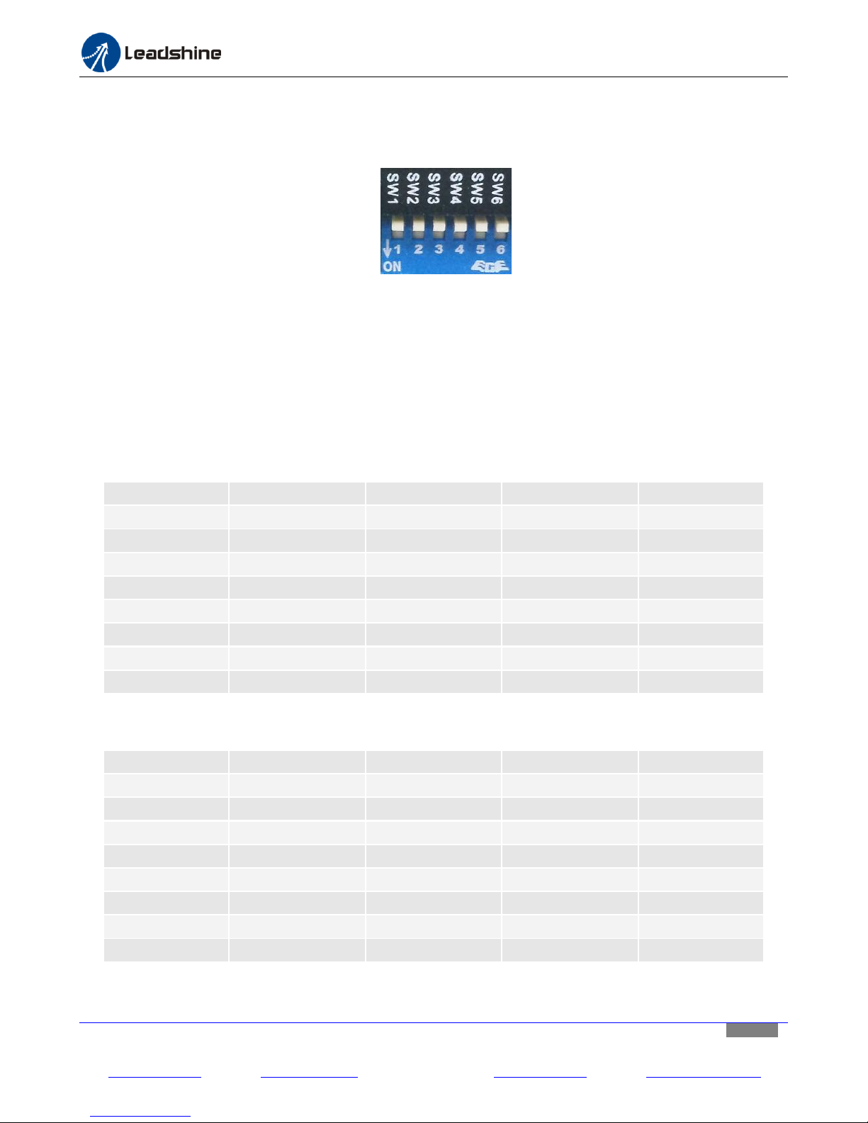
Figure 12 DIP switch for current & micro step configurations
12.1. Configuring Output Current
The output current configuration is required. Use SW1, SW2, and SW3 of the 6-pin DIP switch (Figure 12) of a
stepper drive module to configure the output current to the driven stepper motor. Refer to Table 1 and Table 2
for available output current settings. The MX3660 has two versions. The main difference is current output, as
shown below. Table 1 is for the drives with firmware V1.0b (It’s the latest version or default version.), and Table
2 is for the drives with firmware V1.0a.
For a stepper drive module (V1.0b)
Table 1 Output current settings for a stepper drive module (V1.0b)
For a stepper drive module (V1.0a)
Table 2 Output current settings for a stepper drive module (V1.0a)
Leadshine Technology Co., Ltd Leadshine America, Inc. Page 12/25
11/F, Block A3, iPark, No.1001 Xueyuan Blvd, Nanshan District, Shenzhen, China 25 Mauchly, Suite 318, Irvine, CA 92618, USA
Tel: 86-755-26409254 Fax: 86-755-26402718 Tel: 1-949-608-7270 Fax: 1-949-608-7298
Web: www.leadshine.com Email: [email protected] Web: www.leadshine.com Email: [email protected]
Page 13
Hardware installation manual of the multi-axis drive MX3660
Micro Step
Steps/Rev
SW4
SW5
SW6
Full
200
On
On
On
Half
400
Off
On
On
1 / 4
800
On
Off
On
1 / 8
1600
Off
Off
On
1 / 10
2000
On
On
Off
1 / 16
3200
Off
On
Off
1 / 32
6400
On
Off
Off
1 / 64
12800
Off
Off
Off
12.2. Configuring Micro Step Resolution
The micro step resolution configuration is required. Use pin 4, 5, and 6 of the 6-pin DIP switch (Figure 12) of a
stepper drive module to configure the micro step resolution for the driven stepper motor. Refer to Table 3 for
available micro step resolution settings.
Table3 Micro step settings for a stepper drive module
13. Connecting the DB25 Connector
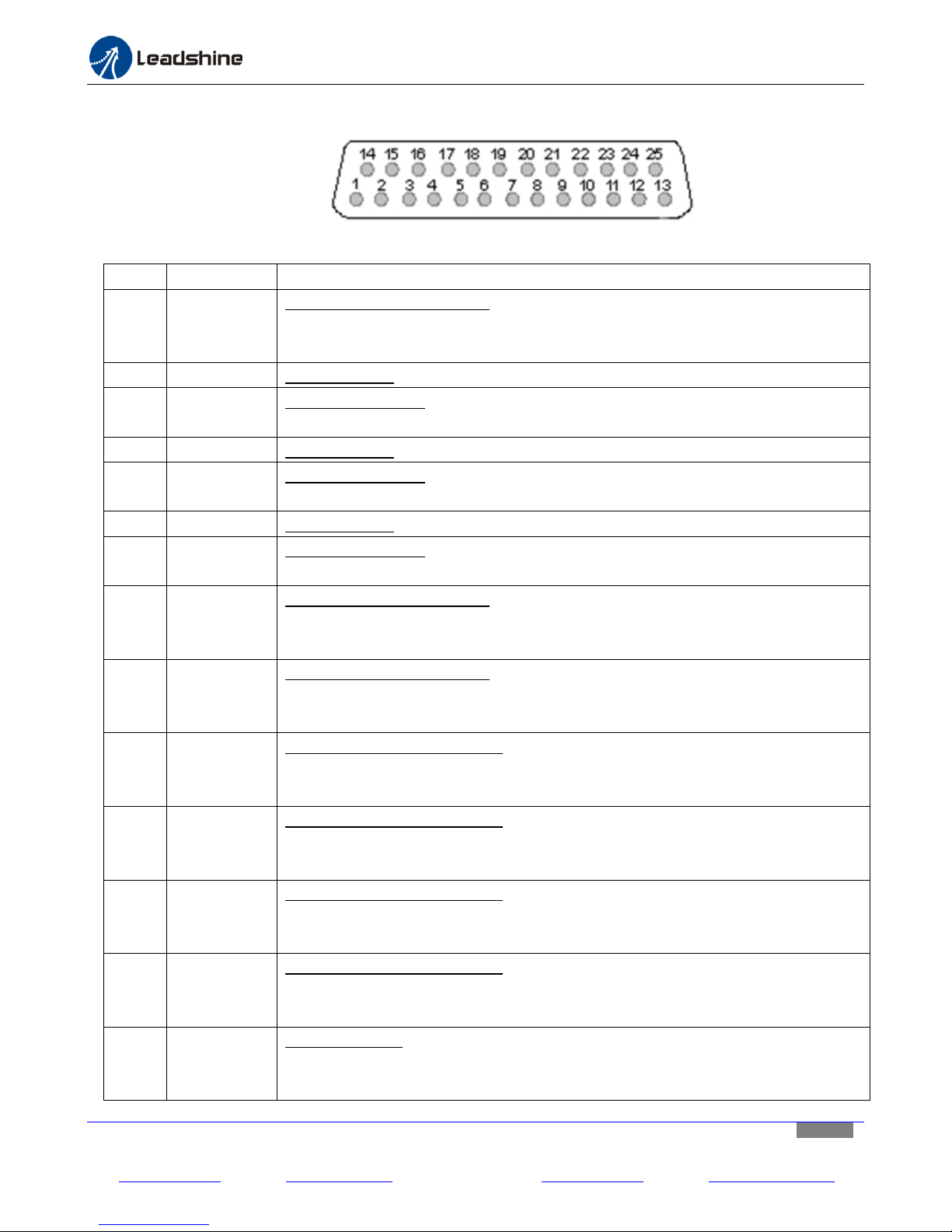
Refer to “Appendix A” for detail specification for the MX3660 DB25 connector pin-out. The DB25 connector is
used to connect, directly / indirectly (e.g. via a circuit board), to a source of control signals (“controller”
hereafter) such as a motion controller, a PLC, an indexer, PC-based control system (e.g. Mach 3, Mach 4, EMC,
WinCNC, etc.).
The controller is the “Brain” of the whole motion control system for: (1) sending signals of step, direction, and
charge pump, to control the MX3660; (2) sending digital/analog signals for the controls of external devices,
which are connected at the MX3660 digital output connector; (3) accepting “Fault” output from the MX3660; (4)
take input signals sent from the external devices connected at the MX3660 digital input connector.
We will only depict the pin connections for step & direction, fault output, charge pump, and PWM. Refer to
Appendix A for pin outs for other optional I/O’s
13.1. Connecting the DB25 Step & Direction Pins
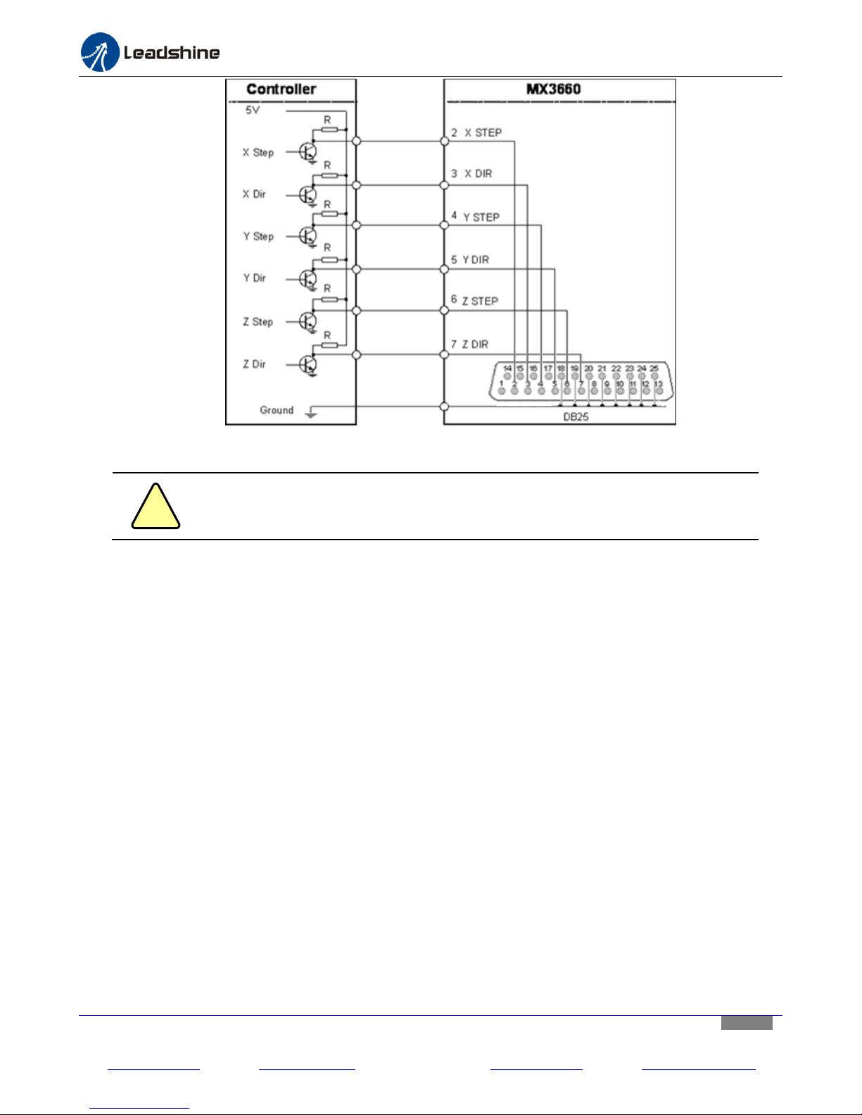
The step and direction pin connections are required. Step signals are sent to the MX3660 via pin 2, 4, 6 of the
DB25 connector. Direction signals are sent to the MX3660 via pin 3, 5, 7. Refer to Figure 13.
Step and direction signal voltage should be 3.3-5 VDC and “Active High”. In the controller configuration, the step
width should be configured to a value at least 2.5 uS, and direction setup time needs to be at least 5 uS.
Otherwise, it could cause loss of steps, or no motion at all for the controlled stepper motors.
Leadshine Technology Co., Ltd Leadshine America, Inc. Page 13/25
11/F, Block A3, iPark, No.1001 Xueyuan Blvd, Nanshan District, Shenzhen, China 25 Mauchly, Suite 318, Irvine, CA 92618, USA
Tel: 86-755-26409254 Fax: 86-755-26402718 Tel: 1-949-608-7270 Fax: 1-949-608-7298
Web: www.leadshine.com Email: [email protected] Web: www.leadshine.com Email: [email protected]
Page 14
Hardware installation manual of the multi-axis drive MX3660
!
Caution
If step & direction signal voltage is lower than 5 VDC, you may need to increase step
width and direction setup time (> 5 uS) to move your motors, or avoid loss of step.
Figure 13 Connecting the step & direction signals of a controller to the MX3660
13.2. Connecting the DB25 Fault Output Pin
The fault pin connection is optional. The MX3660 3-axis stepper drive will send a “Fault” output signal of 5 VDC
back to the controller via Pin 15 (Appendix A) of the DB25 connector, in one of the following scenario:
Any of the 3 stepper drive module is in protection mode including over voltage and over current. Read
“Protection” detail in the MX3660 datasheet.
The connected external E-Stop switch in the digital input is pressed.
With the receiving of a fault received from the MX3660, a controller can be notified an abnormal event has
happened. It can then react, such as shutting down the whole control machine/device for machine damage.
13.3. Connecting the DB 25 Charge Pump Pin
The charge pump pin connection is optional. To implement the “charge pump” feature of the MX3660 3-axis
stepper drive, turn off the Pulse Switch (page 7) and keep sending 10 kHz signals to Pin 16 of the DB25 connector
while the controller works properly. In this scenario, the “PULSE LED” on the MX3660 will be turned on to
indicate that everything is fine. When no such signal received, the MX3660 will be disabled with the “PULSE
LED” light off, to prevent from any further action caused by controller malfunction for connected stepper motors
and external devices. Read “Enabling / Disabling Charge Pump” in page 7 for additional information.
Connecting the DB25 PWM Pin
The PWM pin connection is optional. The MX3660 can take PWM signals from the controller, through Pin 14 of
Leadshine Technology Co., Ltd Leadshine America, Inc. Page 14/25
11/F, Block A3, iPark, No.1001 Xueyuan Blvd, Nanshan District, Shenzhen, China 25 Mauchly, Suite 318, Irvine, CA 92618, USA
Tel: 86-755-26409254 Fax: 86-755-26402718 Tel: 1-949-608-7270 Fax: 1-949-608-7298
Web: www.leadshine.com Email: [email protected] Web: www.leadshine.com Email: [email protected]
Page 15

Hardware installation manual of the multi-axis drive MX3660
the DB25 connector, transform it into an analog signal, and output as analog voltage signal at the “0-10V” pin of
the analog output connector (Figure 3). This will allow the control of an external analog device such as a VFD for
spindle speed control in a CNC router.
Leadshine Technology Co., Ltd Leadshine America, Inc. Page 15/25
11/F, Block A3, iPark, No.1001 Xueyuan Blvd, Nanshan District, Shenzhen, China 25 Mauchly, Suite 318, Irvine, CA 92618, USA
Tel: 86-755-26409254 Fax: 86-755-26402718 Tel: 1-949-608-7270 Fax: 1-949-608-7298
Web: www.leadshine.com Email: [email protected] Web: www.leadshine.com Email: [email protected]
Page 16
Hardware installation manual of the multi-axis drive MX3660
!
Warning
When the input voltage of the main power supply is higher than 24 VDC, you can NOT
use it to supply power to the 4 digital outputs, and another power source or 5-24
power supply has to be used.
Input 1+
GND
MX3660
Home Switch
Normal open
14. Optional Connections for Inputs/Outputs
The MX3660 3-axis stepper drive is equipped with 4 built-in digital inputs, 4 digital outputs, and one 0-10 V analog
output. Those connections are totally optional and not required to make the MX3660 work.
14.1. Connecting the Digital Inputs
The digital input connections are optional. The 4 general digital inputs are located at the Digital Input Connector
(Figure 3) of the MX3660. They are named as Input 1, Input 2, Input 3, and Input 4. They can be used for any
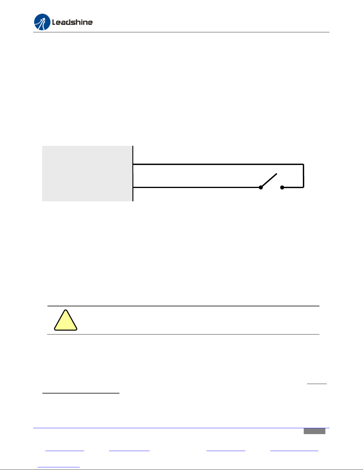
purpose such as connecting limit/home switches. Connect one end of your device wire to the “Input X” (X can
be 1, 2, 3, or 4) pin, and the other wire to “GND” pin next to the input pin (for one wire device, short it to GND).
On Figure 14, it shows how to connect a home/limit switch to digital input “Input 1”.
Figure 14 Home / limit switch connections of the MX3660
14.2. Connecting the Digital Outputs
The digital Output Connections are optional. The 4 general digital outputs are located at the Digital Output
Connector (Figure 3) of the MX3660, named as Output 1, Output 2, Output 3, and Output 4. They can be used
for any purpose such as a DC relay for coolant in a CNC router. They are connected to Pin 17, 1, 8, and 9 of the
DB25 connector respectively. They can be used for other purpose such as a DC relay for coolant in a CNC router.
Connect one end of the load to “Output X+” (X can be 1, 2, 3, or 4) pin and the other end to the VDC+ of a
5-24VDC power source. Then, connect the related “Output X-” pin of the MX3660 to the power supply VDC-.
Those digital outputs are rated at max 70mA. Refer to figure 16 of “MX3660 Connection Diagram”.
14.3. Connecting the Analog Output
The analog output connection is optional. The MX3660 3-axis stepper drive also comes with an opto-isolated
analog output (Figure 3) to allow control of an external device with analog input command, such as a VFD for
spindle control. Supply voltage for the analog device is 5-15 VDC, and the output voltage signal is 0 to (Analog
Supply Voltage minus 1.1 VDC).
On Figure 15, it shows how to connect a VFD to the opto-isolated analog output. Connect the VFD 10 VDC power
wire to “+10 VDC” pin, “Input” wire to “0-10V”, and GND wire to “GND”, and
Leadshine Technology Co., Ltd Leadshine America, Inc. Page 16/25
11/F, Block A3, iPark, No.1001 Xueyuan Blvd, Nanshan District, Shenzhen, China 25 Mauchly, Suite 318, Irvine, CA 92618, USA
Tel: 86-755-26409254 Fax: 86-755-26402718 Tel: 1-949-608-7270 Fax: 1-949-608-7298
Web: www.leadshine.com Email: [email protected] Web: www.leadshine.com Email: [email protected]
Page 17
Hardware installation manual of the multi-axis drive MX3660
MX3660
+10V
INPUT
GND
+10Vdc
0-10V
EGND
VFD
Figure 15 Connecting a VFD to the MX3660
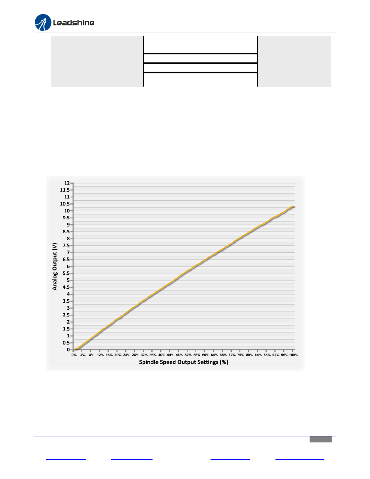
Figure 16 shows the relationship of the spindle speed output in Mach3 and analog output of the MX3660.
Testing conditions:
(1) Used MACH3, settings: PWMBase Freq. = 10, Minimum PWM = 0%,
(2) Used “+12Vdc Out”, the 12VDC auxiliary power output on the MX4660 as the power input for “+10Vdc in”
of the VFD (The measured value of the “+12VDC auxiliary power output of the M3660” was:11.98VDC.).
(3) Device for measuring voltage was Agilent digital oscilloscope DSO-X 3014A. (The raw data of the testing
results are available on request.)
Figure 16 Spindle output & analog output of the MX3660
Leadshine Technology Co., Ltd Leadshine America, Inc. Page 17/25
11/F, Block A3, iPark, No.1001 Xueyuan Blvd, Nanshan District, Shenzhen, China 25 Mauchly, Suite 318, Irvine, CA 92618, USA
Tel: 86-755-26409254 Fax: 86-755-26402718 Tel: 1-949-608-7270 Fax: 1-949-608-7298
Web: www.leadshine.com Email: [email protected] Web: www.leadshine.com Email: [email protected]
Page 18
Hardware installation manual of the multi-axis drive MX3660
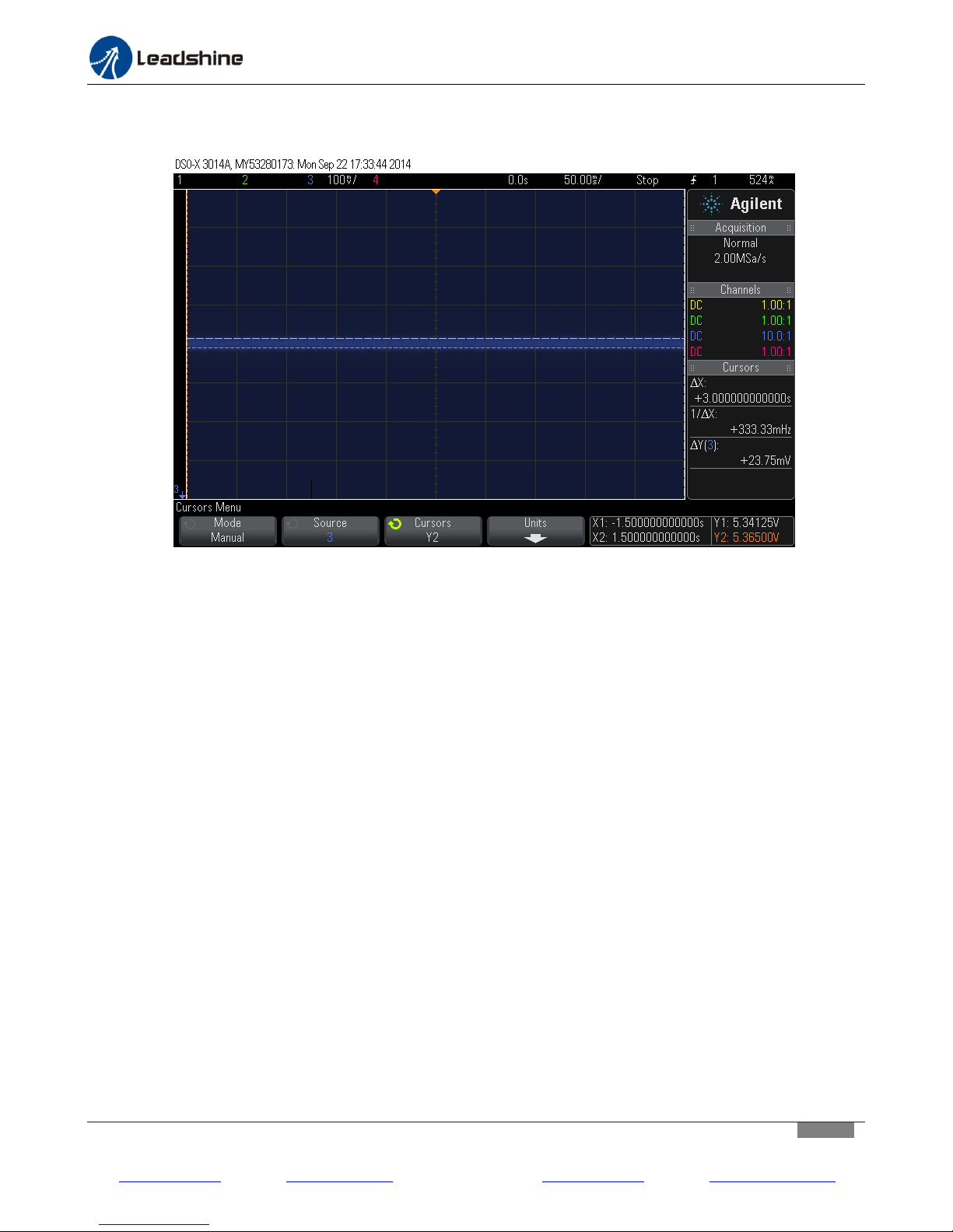
The precision of the analog output is related to PWMBase Freq. parameter settings. When set PWMBase Freq. =
80 Hz, the precision/resolution reached to +/- 11.875 mV. See Figure 17 below.
Figure 17 PWMBase Freq. parameter settings & analog output precision
Leadshine Technology Co., Ltd Leadshine America, Inc. Page 18/25
11/F, Block A3, iPark, No.1001 Xueyuan Blvd, Nanshan District, Shenzhen, China 25 Mauchly, Suite 318, Irvine, CA 92618, USA
Tel: 86-755-26409254 Fax: 86-755-26402718 Tel: 1-949-608-7270 Fax: 1-949-608-7298
Web: www.leadshine.com Email: [email protected] Web: www.leadshine.com Email: [email protected]
Page 19
Hardware installation manual of the multi-axis drive MX3660
Appendix A: MX3660 Connection Diagram
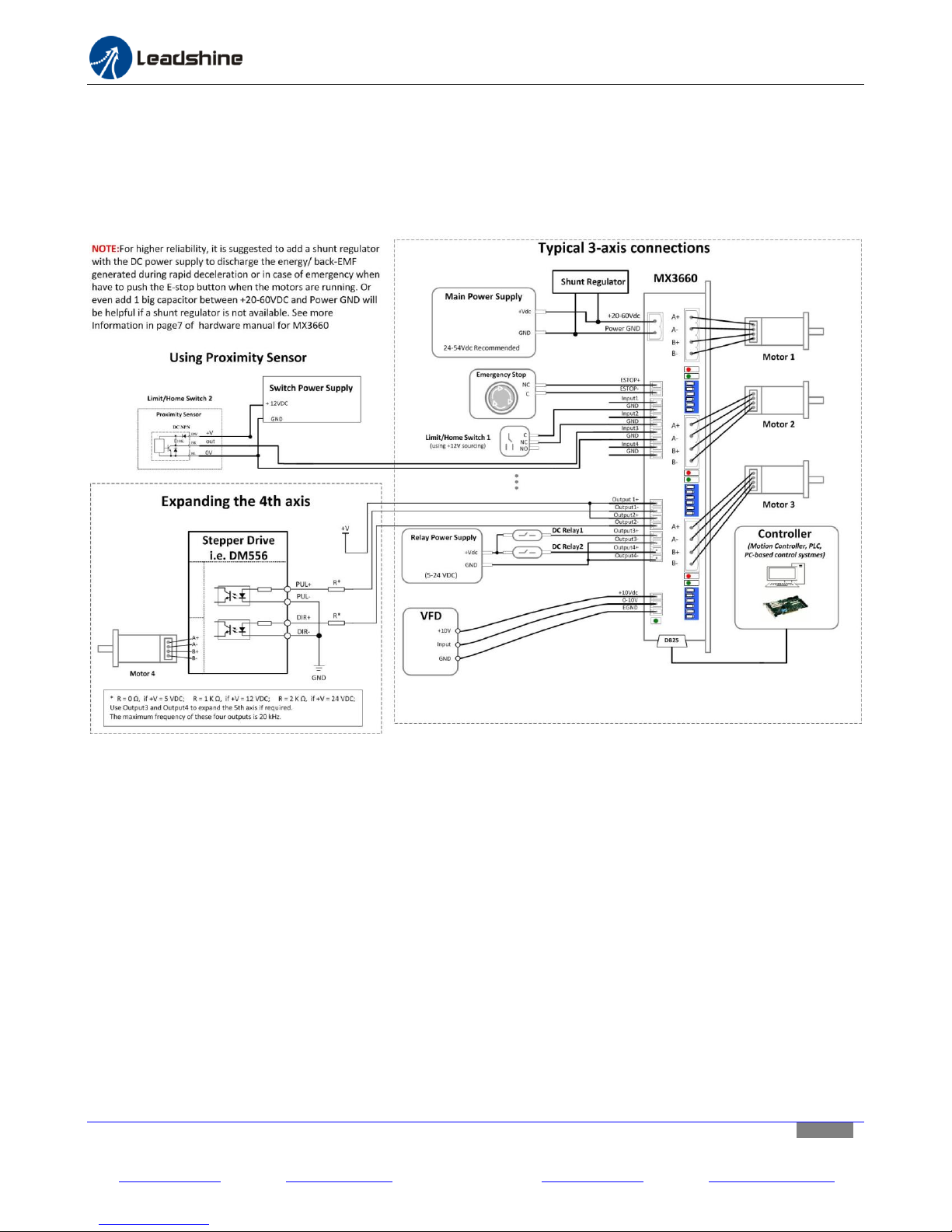
When implemented properly, the MX3660 can be used to power three 2 phase (1.8°) stepper motors of NEMA 17,
23, 24, and 34. In addition, it can also allow controls of optional external devices via the built-in digital inputs, digital
outputs, and the opto-isolated analog output. Figure 18 illustrates the MX3660 connection diagram with 3 stepper
motors. External devices through MX3660 I/O connections are optional at a user’s choice.
Figure 18 MX3660 Connection Diagram
Leadshine Technology Co., Ltd Leadshine America, Inc. Page 19/25
11/F, Block A3, iPark, No.1001 Xueyuan Blvd, Nanshan District, Shenzhen, China 25 Mauchly, Suite 318, Irvine, CA 92618, USA
Tel: 86-755-26409254 Fax: 86-755-26402718 Tel: 1-949-608-7270 Fax: 1-949-608-7298
Web: www.leadshine.com Email: [email protected] Web: www.leadshine.com Email: [email protected]
Page 20
Hardware installation manual of the multi-axis drive MX3660
Pin
Name
Description
1
INPUT 2
General purpose digital input. It is connected to “Output 2” of the digital output
connector (CN7 on Figure 3). Used to forward an input signal sent from the connected
motion controller to the device connected at “Output 2”.
2
X-AXIS STEP
Input step signal for the X-axis stepper drive board.
3
X-AXIS
DIRECTION
Input direction signal for the X-axis stepper drive board.
4
Y-AXIS STEP
Input step signal for the Y-axis stepper drive board.
5
Y-AXIS
DIRECTION
Input direction signal for the Y-axis stepper drive board.
6
Z-AXIS STEP
Input step signal for the Z-axis stepper drive board.
7
Z-AXIS
DIRECTION
Input direction signal for the Z-axis stepper drive board.
8
INPUT 3
General purpose digital input. It is connected to “Output 3” of the digital output
connector (CN7 on Figure 3). Used to forward an input signal sent from the connected
motion controller to the device connected at “Output 3”.
9
INPUT 4
General purpose digital input. It is connected to “Output 4” of the digital output
connector (CN7 on Figure 3). Used to forward an input signal sent from the connected
motion controller to the device connected at “Output 4”.
10
OUTPUT 1
General purpose digital output. It is connected to “Input 1” of the digital input
connector (CN6 on Figure 3). Used to forward an output signal from the device
connected at “Input 1”, to the motion controller.
11
OUTPUT 2
General purpose digital output. It is connected to “Input 2” of the digital input
connector (CN6 on Figure 3). Used to forward an output signal from the device
connected at “Input 2”, to the motion controller.
12
OUTPUT 3
General purpose digital output. It is connected to “Input 3” of the digital input
connector (CN6 on Figure 3). Used to forward an output signal sent from the device
connected at “Input 3”, to the motion controller.
13
OUTPUT 4
General purpose digital output. It is connected to “Input 4” of the digital input
connector (CN6 on Figure 3). Used to forward an output signal sent from the device
connected at “Input 4”, to the motion controller.
14
PWM
PWM pulse input. Used to get the PWM signal from the controller which will be then
transformed into an analog signal to an external device connected at “0-10 DC” pin of
the analog output connector (Figure 3), such as a VFD for spindle speed control.
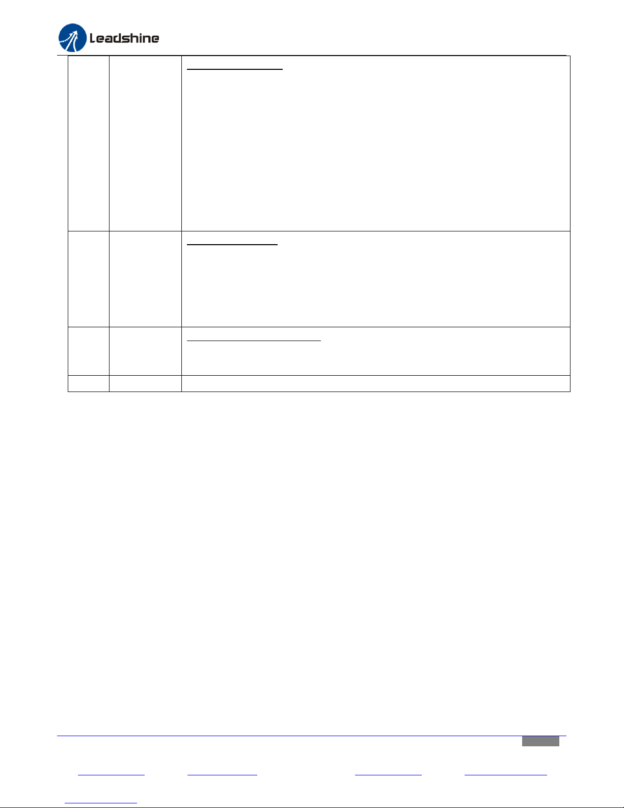
Appendix B: DB25 Connector Pinout
Figure 19 DB25 connector pin assignments
Leadshine Technology Co., Ltd Leadshine America, Inc. Page 20/25
11/F, Block A3, iPark, No.1001 Xueyuan Blvd, Nanshan District, Shenzhen, China 25 Mauchly, Suite 318, Irvine, CA 92618, USA
Tel: 86-755-26409254 Fax: 86-755-26402718 Tel: 1-949-608-7270 Fax: 1-949-608-7298
Web: www.leadshine.com Email: [email protected] Web: www.leadshine.com Email: [email protected]
Page 21
Hardware installation manual of the multi-axis drive MX3660
15
FAULT
Fault signal output. The fault pin connection is optional. Pin 15 is a
Pull-Down-Connection.
TTL level high: Fault
TTL level low: No fault.
TTL level high will be in one of the following scenario:
• Any of the 3 stepper drive module is in protection mode including over voltage and
over current. Read “Protection” detail in the MX3660 datasheet.
• The connected external E-Stop switch in the digital input is pressed.
With the receiving of a fault from the MX3660, a controller can be notified an
abnormal event has happened. It can then react, such as shutting down the whole
control machine/device for machine damage.
16
CHARGE
PUMP
General digital input. A watchdog timer to enable/disable the MX3660. When “Pulse
Switch” (Figure 3) is set to “OFF” position (Charge pump feature not turned off), the
MX3660 will be only enabled with 10 KHz signal receiving at this PIN. Otherwise (no
such signal received), the MX3660 will be disabled. For example, in Mach3 controlled
CNC applications, the MX3660’s enabling/disabling will depend on the receiving of
“Charge Pump” signal from Mach 3.
17
INPUT 1
General purpose digital input. It is connected to “Output 1” of the digital output
connector (CN7 on Figure 3). Used to forward an input signal sent from the connected
motion controller to the device connected at “Output 1”.
18-25
GND
Ground
Leadshine Technology Co., Ltd Leadshine America, Inc. Page 21/25
11/F, Block A3, iPark, No.1001 Xueyuan Blvd, Nanshan District, Shenzhen, China 25 Mauchly, Suite 318, Irvine, CA 92618, USA
Tel: 86-755-26409254 Fax: 86-755-26402718 Tel: 1-949-608-7270 Fax: 1-949-608-7298
Web: www.leadshine.com Email: [email protected] Web: www.leadshine.com Email: [email protected]
Page 22
Hardware installation manual of the multi-axis drive MX3660
Name
Description
Estop+
Emergency stop input (12V Sourcing). When activated, all three drive boards will be shut down and
the MX3660 will stop working. The red LED of each drive module will blink three times periodically
every 4 seconds to indicate an emergency event signal received. In this case, a fault output will be
sent to pin 15 - “Fault”- of the DB25 connector to notify the connected motion controller.
Estop-
Common ground
Input 1
General purpose Input (12V sourcing). This pin is connected to pin 10 - “Output 1” - of the DB25
connector. Used to forward the digital output signal, sent from the connected external device here, to
the motion controller connected through the DB25 connector.
GND
Common ground
Input 2
General purpose Input (12V sourcing). This pin is connected to pin 11 - “Output 2” - of the DB25
connector. Used to forward the digital output signal, sent from the connected external device here, to
the motion controller connected through the DB25 connector.
GND
Common ground
Input 3
General purpose Input (12V sourcing). This pin is connected to pin 12 - “Output 3” - of the DB25
connector. Used to forward the digital output signal, sent from the connected external device here, to
the motion controller connected through the DB25 connector.
GND
Common ground
Input 4
General purpose Input (12V Sourcing). This pin is connected to pin 13 - “Output 4” - of the DB25
connector. Used to forward the digital output signal, sent from the connected external device here, to
the motion controller connected through the DB25 connector.
GND
Common ground
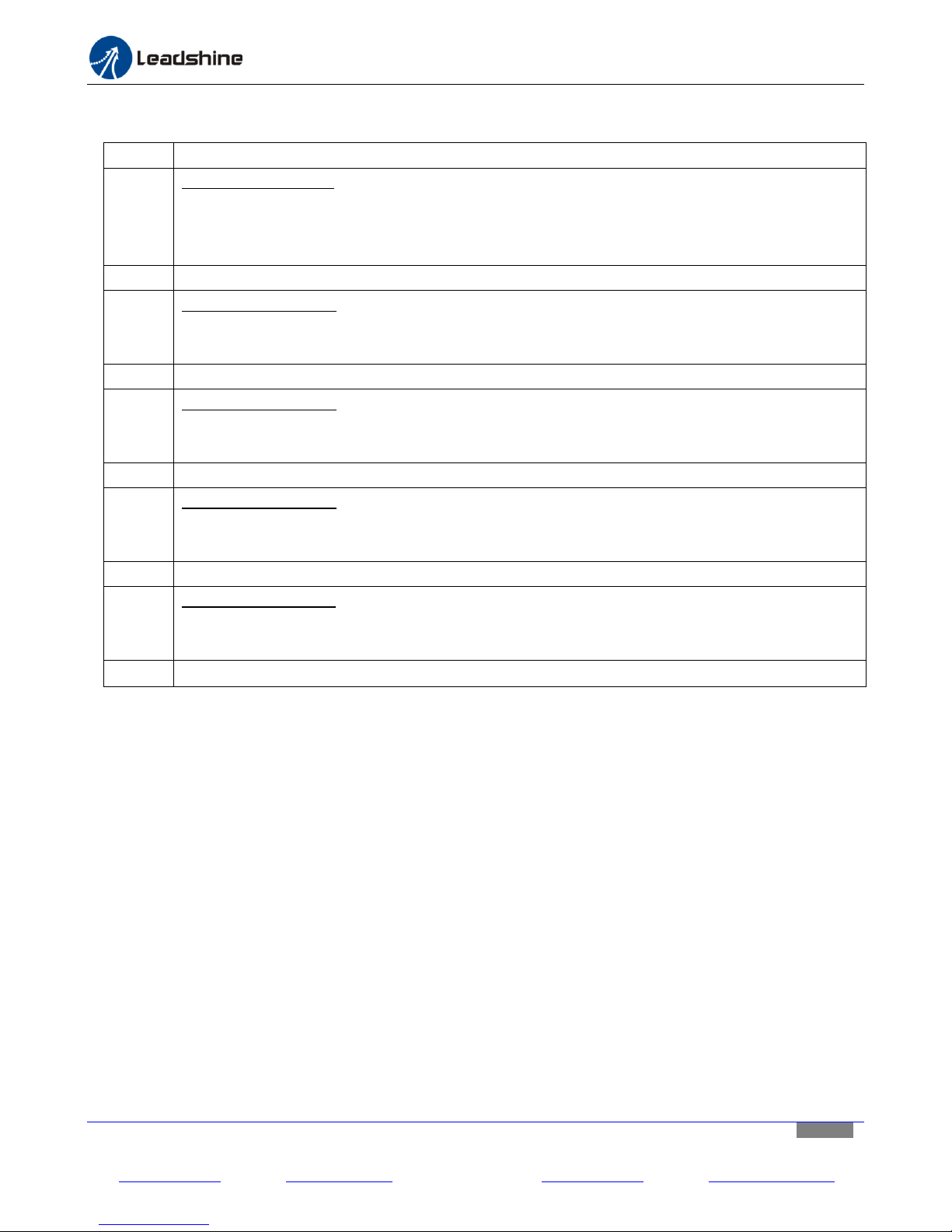
Appendix C: Digital Inputs
Leadshine Technology Co., Ltd Leadshine America, Inc. Page 22/25
11/F, Block A3, iPark, No.1001 Xueyuan Blvd, Nanshan District, Shenzhen, China 25 Mauchly, Suite 318, Irvine, CA 92618, USA
Tel: 86-755-26409254 Fax: 86-755-26402718 Tel: 1-949-608-7270 Fax: 1-949-608-7298
Web: www.leadshine.com Email: [email protected] Web: www.leadshine.com Email: [email protected]
Page 23
Hardware installation manual of the multi-axis drive MX3660
Name
Description
Output 1 +
General purpose output (max 24V@70mA). This pin is connected to pin 17 - “Input 1” - of the
DB25 connector. Used to output the digital signal, sent through DB25 “Input 1” from the motion
controller, to the connected external device here.
Output 1-
General purpose output - for Output 1
Output 2 +
General purpose output (max 24V@70mA). The pin is connected to pin 1 - “Input 2” - of the DB25
connector. Used to output the digital signal, sent through DB25 “Input 2” from the motion
controller, to the connected external device here.
Output 2-
General purpose output - for Output 2
Output 3 +
General purpose output (max 24V@70mA). This pin is connected to pin 8 - “Input 3” - of the DB25
connector. Used to output the digital signal, sent through DB25 “Input 3” from the motion
controller, to the connected external device here.
Output 3-
General purpose output - for Output 3
Output4 +
General purpose output (max 24V@70mA). This pin is connected to pint 9 - “Input 4” - of the DB25
connector. Used to output the digital signal, sent through DB25 “Input 4” from the motion
controller, to the connected external device here.
Output 4-
General purpose output - for Output 4
Name
Description
+10V
Power source connection pin for the connected analog external device (e.g. VFD), connected at the
analog output connector. Voltage range of 5-15VDC.
0-10V
Voltage output to control the external analog device. The powered voltage is 0 to supplied power
voltage minus 1.1 VDC. This pin is used to control the external analog device by the controller
through PWM signals accepted at PIN 14 of the DB25 connector. Read pin 14 - “PWM” - of the
DB25 Connector for more information.
EGND
External +10V ground
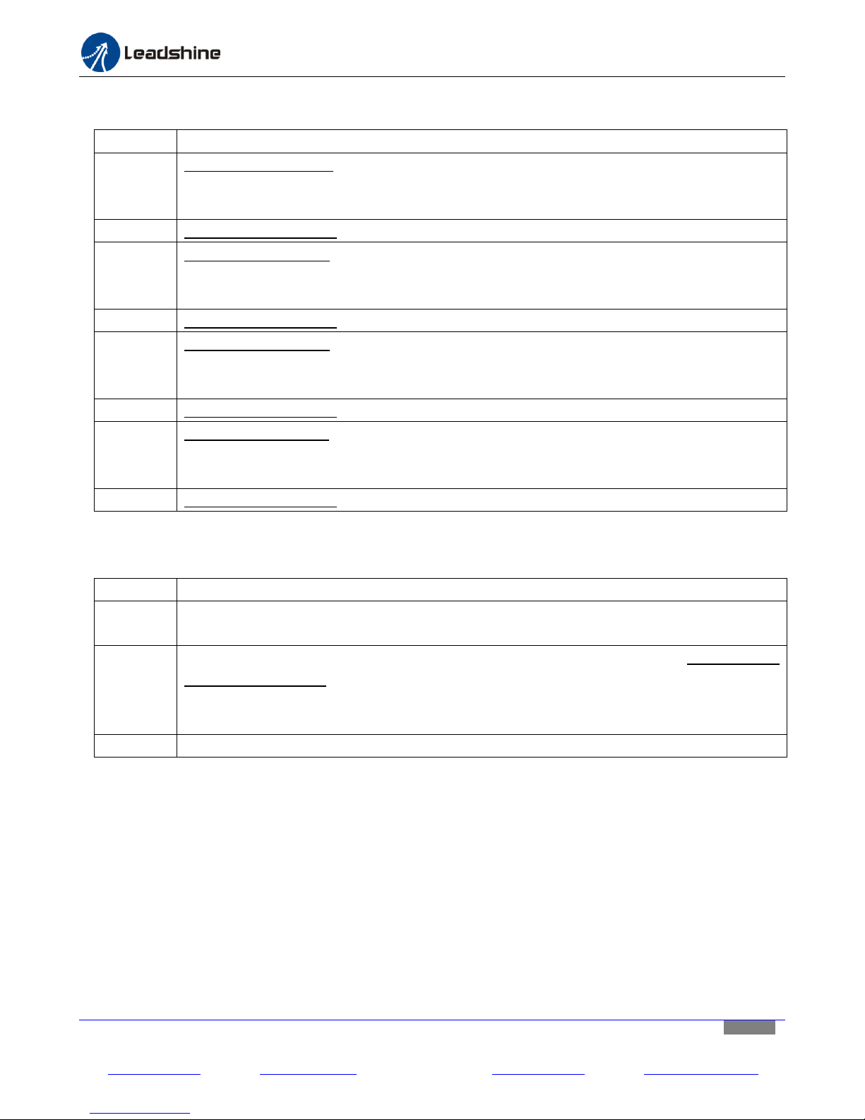
Appendix D: Digital Outputs
Appendix E: Opto-Isolated Analog Output
Leadshine Technology Co., Ltd Leadshine America, Inc. Page 23/25
11/F, Block A3, iPark, No.1001 Xueyuan Blvd, Nanshan District, Shenzhen, China 25 Mauchly, Suite 318, Irvine, CA 92618, USA
Tel: 86-755-26409254 Fax: 86-755-26402718 Tel: 1-949-608-7270 Fax: 1-949-608-7298
Web: www.leadshine.com Email: [email protected] Web: www.leadshine.com Email: [email protected]
Page 24
Hardware installation manual of the multi-axis drive MX3660
Symptoms
Possible Cause
Solution
A motor doesn’t
move
No power
Connect Power
Wrong signal and / or stepper
motor connection
Correct the DB25 connector and / or stepper motor
connection(s)
No E-Stop connection
Option 1: connect an E-Stop switch. Or,
Option 2: short “E-Stop +” and “E-Stop+” pins
The stepper drive modules is
under protection
Make sure the power supply voltage is not too high.
Also look into your mechanic systems and make sure
it does not cause over current protection.
Control signal voltage is too low
Increase step width.
Motor spins in wrong
direction
Wrong motor wiring
Reverse wires on one phase of the stepper motor
Loss of steps
Wrong step enabling setting in
your controller
By default, MX3660 step enabling is “Active High”.
Change your step enabling configuration of your
controller to “Active High” also.
Direction set up time is too
short
Increase the direction set up time in your controller
to at least two times of pulse width
Interference
Shield your signal cables and keep the MX3660 as far
as possible, from other electronic components
Appendix F: Stepper Drive Module Replacement
In the case that one of the three stepper drive modules of the MX3660 does not work (the green LED light is not on
when the MX3660 is powered on) you can replace it with a Leadshine SDM660 stepper drive module. Contact us for
getting a new SDM660.
Appendix G: Warranty Information
The MX3660 3-axis stepper drive comes with 12-month limited warranty under proper use. Contact your MX3660
supplier first for warranty service. If your MX3660 was bought through Leadshine or one of its subsidiaries, contact
us directly.
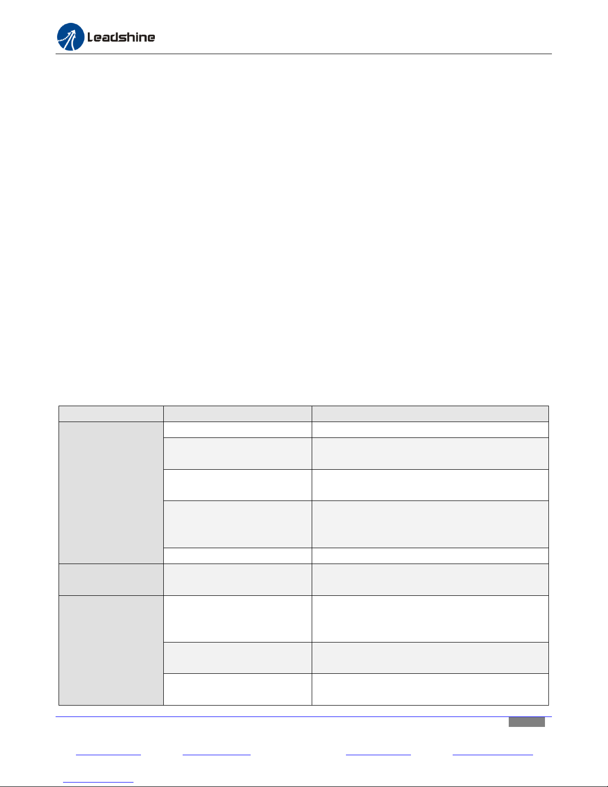
Appendix H: Trouble Shooting
In the case that the MX3660 doesn’t operate properly, the first step is to identify whether the problem is electrical
or mechanical in nature. The next step is to isolate the system component that is causing the problem. As part of
this process you may have to disconnect the individual components that make up your system and verify that they
operate independently. It is important to document each step in the troubleshooting process. You may need this
documentation to refer back to at a later date, and these details will greatly assist our Technical Support staff in
determining the problem should you need assistance.
Many of the problems that affect motion control systems can be traced to electrical noise, controller software
errors, or mistakes in wiring.
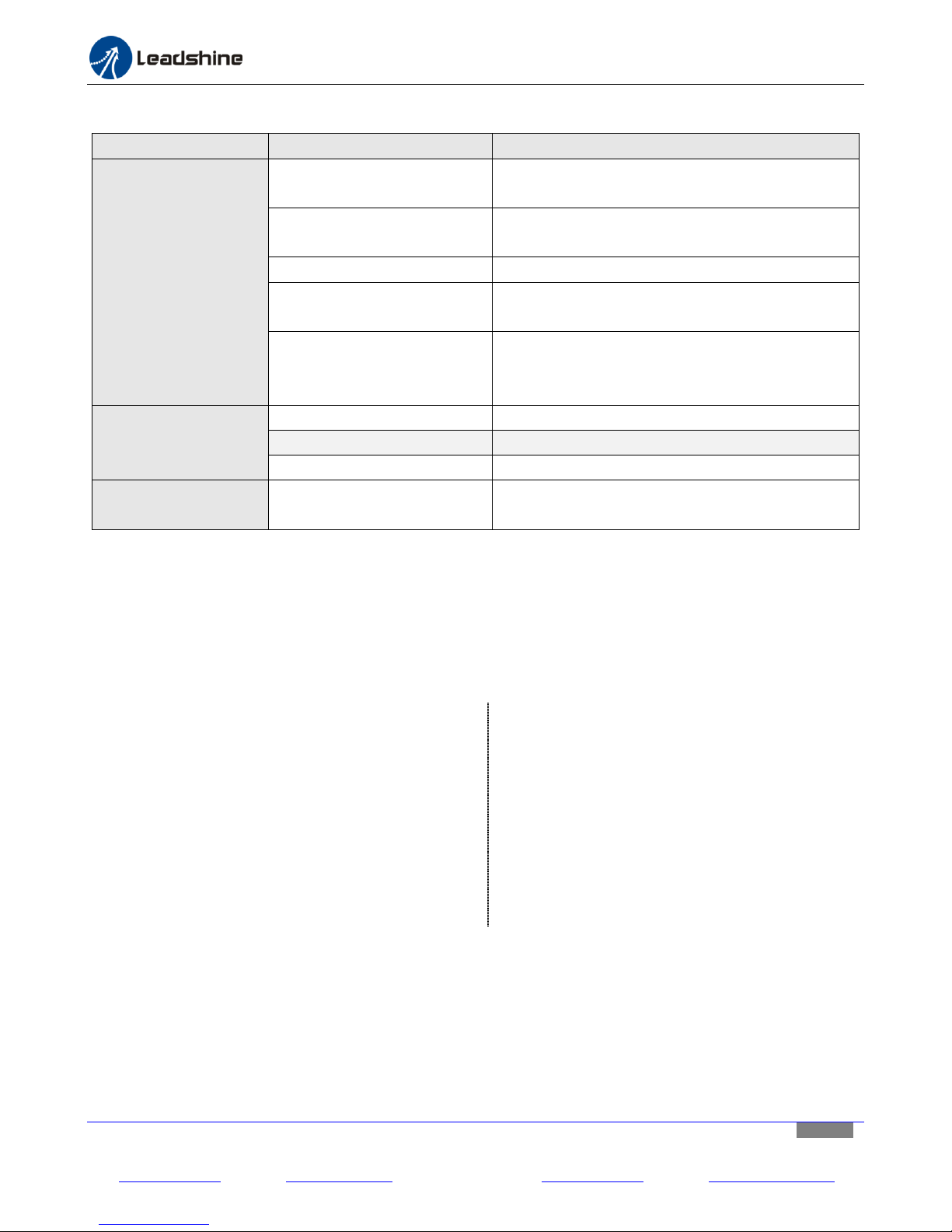
The following table shows some commonly asked symptoms and possible solutions.
Leadshine Technology Co., Ltd Leadshine America, Inc. Page 24/25
11/F, Block A3, iPark, No.1001 Xueyuan Blvd, Nanshan District, Shenzhen, China 25 Mauchly, Suite 318, Irvine, CA 92618, USA
Tel: 86-755-26409254 Fax: 86-755-26402718 Tel: 1-949-608-7270 Fax: 1-949-608-7298
Web: www.leadshine.com Email: [email protected] Web: www.leadshine.com Email: [email protected]
Page 25
Hardware installation manual of the multi-axis drive MX3660
Symptoms
Possible Cause
Solution
The red LED light of a
stepper drive module
blinks
Power supply voltage is too
high
Use a lower voltage power supply (24-54 VDC)
No E-Stop connection
Option 1: connect an E-Stop switch. Or,
Option 2: short “E-Stop +” and “E-Stop+” pins
Damaged stepper motor
Replace your stepper motor
Over current protection caused
by mechanic system
Check and fix the mechanic problem(s) from your
mechanic system.
Acceleration is too fast.
During deceleration, back EMF voltage charge has
enabled drive “Over Voltage” protection. Lower
down you acceleration/deceleration.
Excessive motor and
drive heating
Load is too high
Use a larger motor or motors
Mechanic problem
Check your mechanic system
Bad heating dissipation
Add a fan or other device to improve air circulation
The green light of a
drive module is not on
That stepper drive module is
already damaged
Contact Leadshine for a new stepper drive module
for replacement
Leadshine Headquarters
Address: 11/F, Block A3, iPark
No.1001 Xueyuan Blvd.
Nanshan District, Shenzhen, China
Tel: 86-400-885-5521
Fax: 86-755-2640-2718
Web: www.leadshine.com
Sales Email: [email protected]
Support: [email protected]
Leadshine America, Inc.
Address: 25 Mauchly, Suite 318
Irvine, CA 92608
USA
Tel: 1-949-608-7270
Fax: 1-949-608-7298
Web: www.leadshineusa.com
Sales Email: [email protected]
Support: [email protected]
Appendix F: Trouble Shooting (Continued)
Contact Us
Contact Leadshine HQ, Leadshine USA Inc., or your local authorized Leadshine distributors for sales, technical
support, and other services.
Leadshine Technology Co., Ltd Leadshine America, Inc. Page 25/25
11/F, Block A3, iPark, No.1001 Xueyuan Blvd, Nanshan District, Shenzhen, China 25 Mauchly, Suite 318, Irvine, CA 92618, USA
Tel: 86-755-26409254 Fax: 86-755-26402718 Tel: 1-949-608-7270 Fax: 1-949-608-7298
Web: www.leadshine.com Email: [email protected] Web: www.leadshine.com Email: [email protected]
 Loading...