

Page 1

HBS86H
Hybrid Stepper Servo Drive
Manual
Page 2

-2-
Contents
1. Overview
...........................................................................................- 4-
2. Features
............................................................................................- 4 -
3.Ports Introduction
...........................................................................- 5-
3.1 ALM and PEND signal output ports
......................................- 5-
3.2 Control Signal Input Ports ......................................................- 5-
3.3 Encoder Feedback Signal Input Ports
.....................................- 6-
3.4PowerInterfacePorts..............................................................-7-
4.Technological Index
.........................................................................- 8-
5. Connections to Control Signal
........................................................- 9-
5.1ConnectionstoCommonAnode
.............................................-9-
5.2ConnectionstoCommonCathode
........................................-10-
5.3 Connections to Differential Signal
.......................................- 11-
5.4Connectionsto232SerialCommunicationInterface
...........-12-
5.5 Sequence Chart of Control Signals
.......................................- 12-
6.DIP Switch Setting
.........................................................................- 13-
6.1ActivateEdgeSetting...........................................................-13-
6.2 Running Direction Setting ....................................................- 14-
6.3Micro steps Setting
...............................................................- 14-
7.FaultsalarmandLEDflickerfrequency
.....................................-15-
8. Appearance and InstallationDimensions
....................................- 16 -
9.Typical Connection
........................................................................- 16-
10.Parameter Setting
........................................................................- 17-
11.ProcessingMethodstoCommonProblemsandFaults............-22-
11.1 Power on power light off ....................................................- 22 -
11.2Poweronredalarmlighton
...............................................-22-
11.3 Redalarmlightonafterthemotorrunningasmallangle..-22-
11.4
Afterinputpulsesignalbutthemotornotrunning
.............-23-
Page 3

-3-
1. Overview
The HBS86H hybrid stepper servo drive system integrates
the servo control technology into the digital stepper drive
perfectly. And this product adopts an optical encoder with high
speed position sampling feedback of 50 μ s, once the position
deviation appears, it will be fixed immediately. This product is
compatible the advantages of the stepper drive and the servo
drive, such as lower heat, less vibration, fast acceleration, and so
on. This kind of servo drive also has an excellent costperformance.
2. Features
Without losing step, High accuracy inpositioning
100% rated outputtorque
Variable current control technology, High currentefficiency
Small vibration, Smooth and reliable moving at lowspeed
Accelerate and decelerate control inside, Great improvement in
smoothness of starting or stopping themotor
User-defined microsteps
Compatible with 1000 and 2500 linesencoder
No adjustment in generalapplications
Over current, over voltage and over position errorprotection
Green light means running while red light means protection or
offline
Page 4

-4-
3. Ports Introduction
3.1 ALM and PEND signal outputports
1
2
3
4
Port
Symbol
Name
Remark
1
PEND+
In position signal output +
+
-
2
PEND-
In position signal output -
3
ALM+
Alarm output +
4
ALM-
Alarm output -
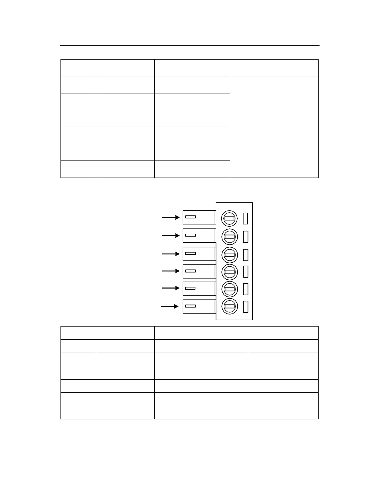
3.2 Control Signal InputPorts
1
2
3
4
5
6
Page 5
-5-
Port
Symbol
Name
Remark
1
PLS+
Pulse signal +
Compatible with
5V or 24V
2
PLS-
Pulse signal -
3
DIR+
Direction signal+
Compatible with
5V or 24V
4
DIR-
Direction signal-
5
ENA+
Enable signal +
Compatible with
5V or 24V
6
ENA-
Enable signal -
3.3 Encoder Feedback Signal InputPorts
1
2
3
4
5
6
Port
Symbol
Name
Wiring color
1
PB+
Encoder phase B +
Blue
2
PB-
Encoder phase B -
White
3
PA+
Encoder phase A +
Yellow
4
PA-
Encoder phase A -
Green
5
VCC
Input power
Red
6
GND
Input power ground
Black
Page 6
-6-
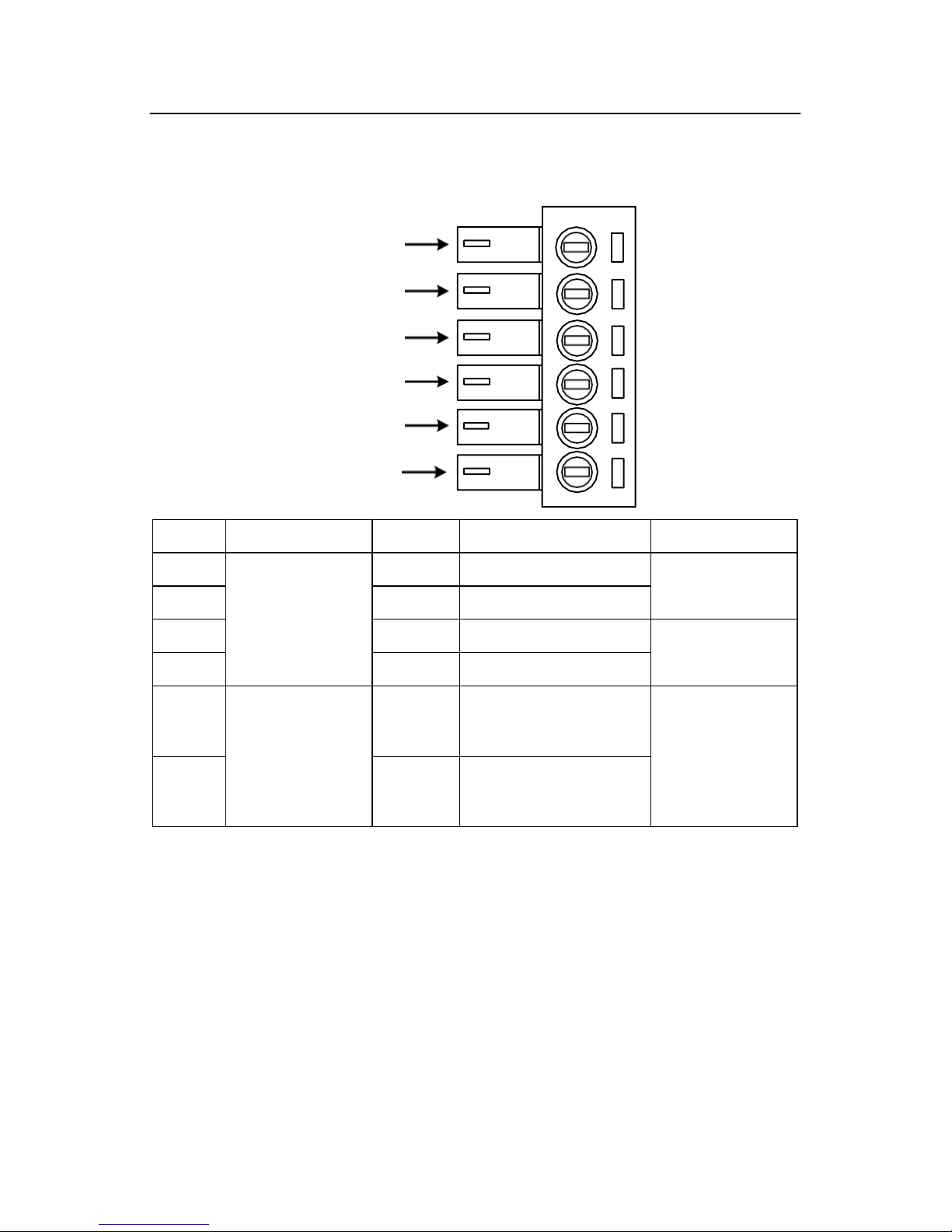
3.4 Power InterfacePorts
1
2
3
4
5
6
Port
Identification
Symbol
Name
Remark
1
Motor Phase
Wire InputPorts
A+
Phase A+(Red)
Motor Phase A
2
A-
Phase A- (Blue)
3
B+
Phase B+(Green)
Motor Phase B
4
B-
Phase B-(Black)
5
Power Input
Ports
VCC
Input Power +
AC24V-70V
DC30V-100V
6
GND
Input Power-
Page 7

-7-
4. Technological Index
Input Voltage
24~70VAC or
30~100VDC
Output Current
6A 20KHz PWM
Pulse Frequency max
200K
Communication rate
57.6Kbps
Protection
Over current peak value12A±10%
Over voltage value130V
The over position error range can be
set through theHISU
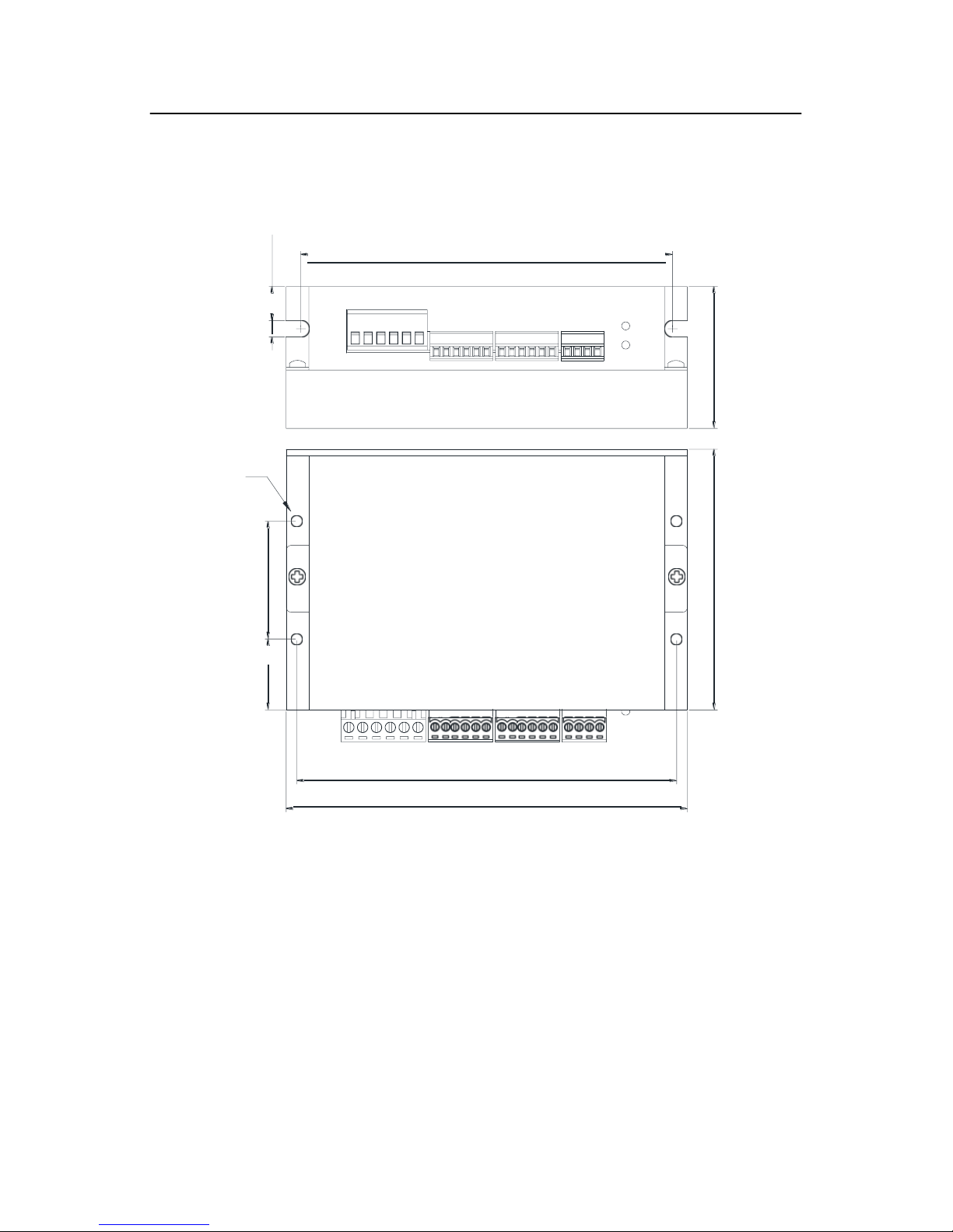
Overall Dimensions(mm)
150×97.5×53
Weight
Approximate 580g
Environment
Specifications
Environment
Avoid dust, oil fog and corrosive gases
Operating
Temperature
70℃ Max
Storage
Temperature
-20℃~+65℃
Humidity
40~90%RH
Cooling
method
Natural cooling or forced air cooling
Page 8

-8-
5. Connections to ControlSignal
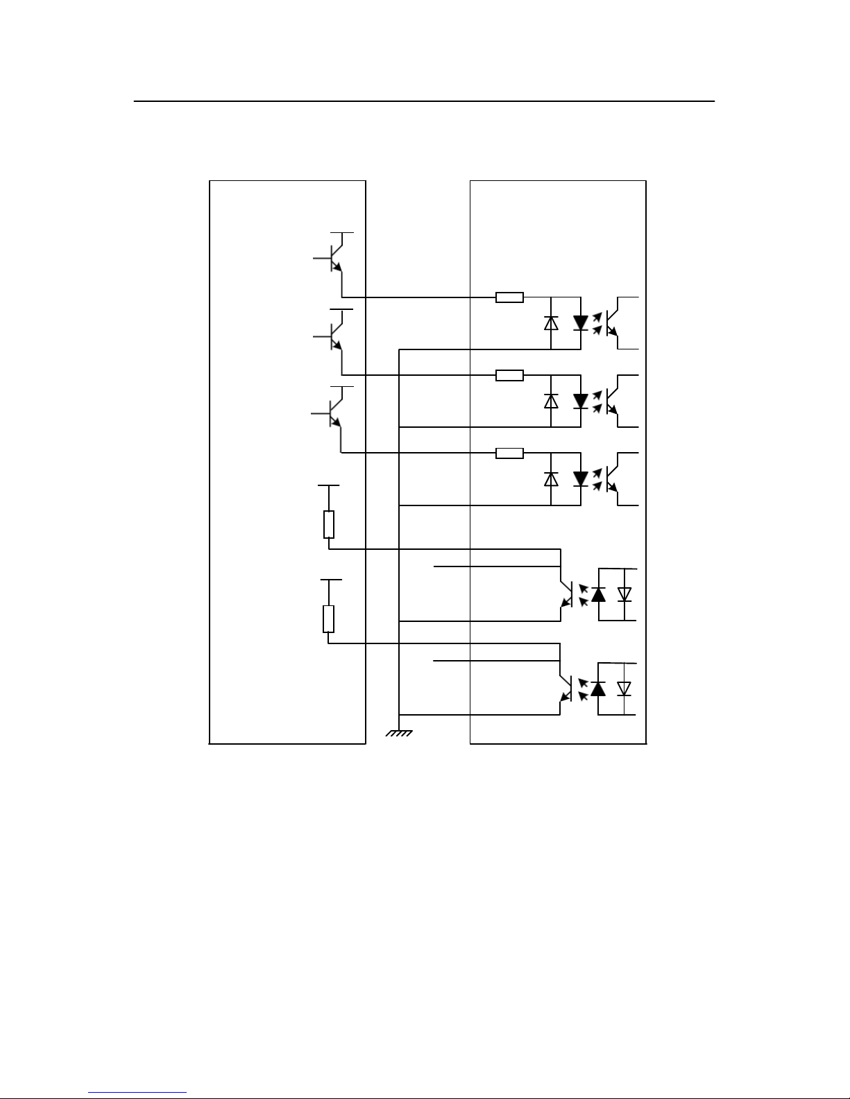
5.1 Connections to CommonAnode
Remark:
VCC is compatible with 5V or 24V;
R(3~5K) must be connected to control signal terminal.
Controller
2HSS86H-KH
Drive
VCC
PUL+
270
PUL-
Pulse
Signal
DIR+
270
DIR-
Direction
Signal
ENA+
270
ENA-
Enable
Signal
VCC R PEND+
VCC
R
PEND-
ALM+
ALM-
Page 9
-9-
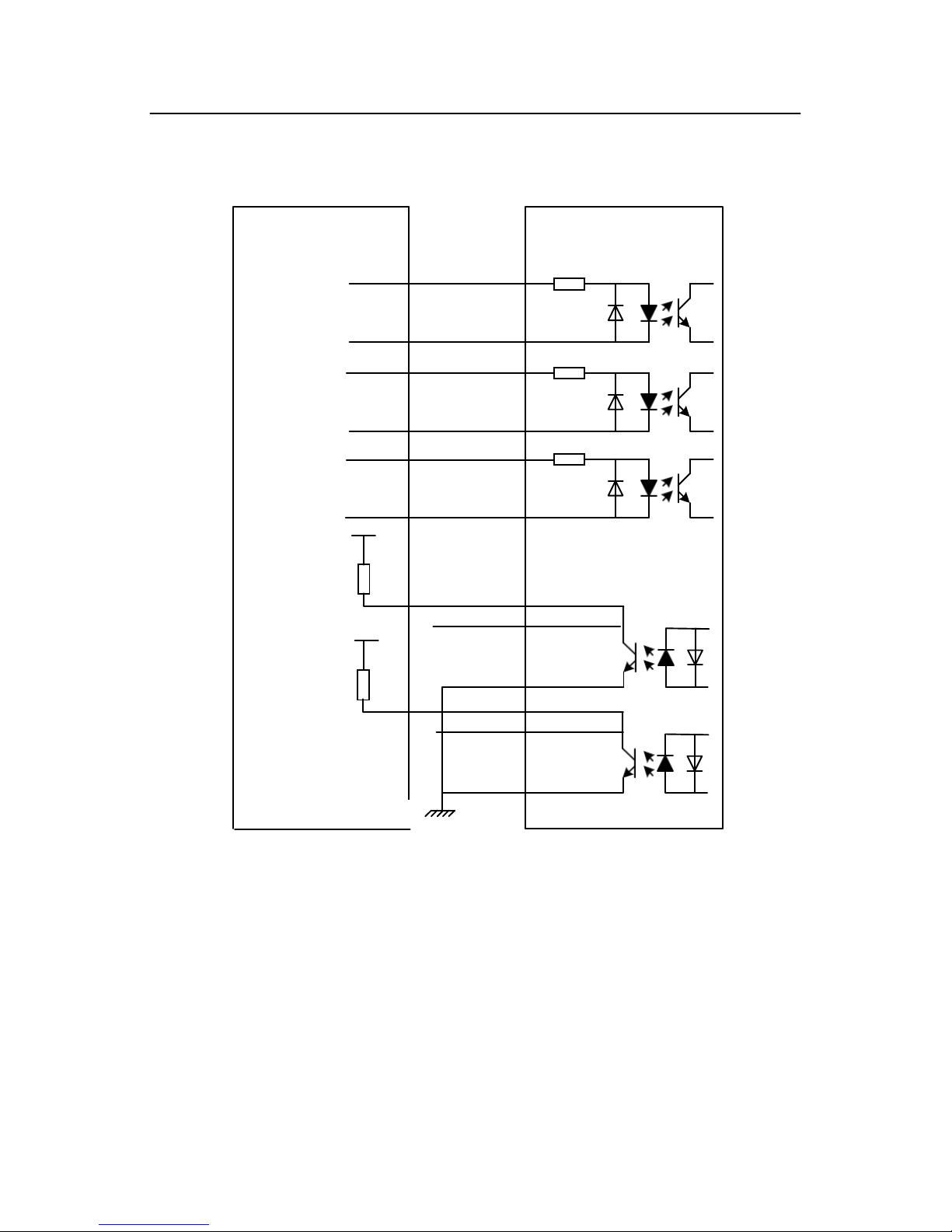
5.2 Connections to CommonCathode
Remark:
VCC is compatible with 5V or 24V;
R(3~5K) must be connected to control signal terminal.
Controller
Pulse
Signal
VCC
2HSS86H-KH
Drive
PUL+
270
VCC
Direction
Signal
PUL-
DIR+
270
VCC
Enable
Signal
DIR-
ENA+
270
VCC
ENA-
R PEND+
VCC
R
PEND-
ALM+
ALM-
Page 10
-10-
5.3 Connections to DifferentialSignal
Remark:
VCC is compatible with 5V or 24V;
R(3~5K) must be connected to control signal terminal.
Controller
2HSS86H-KH
Drive
PUL+
270
Pulse
Signal
PUL-
DIR+
270
Direction
Signal
DIR-
ENA+
270
Enable
Signal
ENA-
VCC
R
PEND+
VCC
R
PEND-
ALM+
ALM-
Page 11

-11-
5.4 Connections to 232 Serial CommunicationInterface
PIN1
PIN6
PIN1
PIN6
Crystal Head
foot
Definition
Remark
1
TXD
Transmit Data
2
RXD
Receive Data
4
+5V
Power Supply to HISU
6
GND
Power Ground
5.5 Sequence Chart of ControlSignals
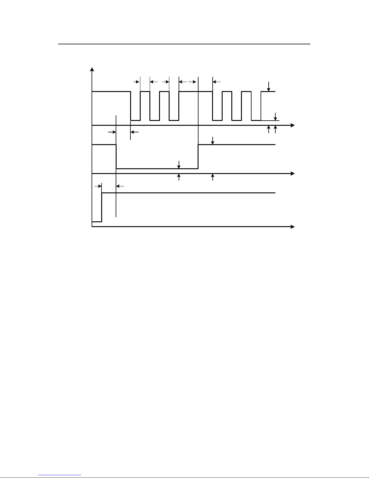
In order to avoid some fault operations and deviations, PUL, DIR
and ENA should abide by some rules, shown as following diagram:
Page 12
-12-
PUL
DIR
ENA
Remark:
PUL/DIR
a. t1: ENA must be ahead of DIR by at least 5μ s. Usually, ENA+ and
ENA- are NC (notconnected).
b. t2: DIR must be ahead of PUL active edge by 6μ s to ensure correct
direction;
c. t3: Pulse width not less than 2.5μs;
d. t4: Low level width not less than 2.5μs.
6. DIP SwitchSetting
6.1 Activate EdgeSetting
SW1 is used for setting the activate edge of the input signal, “off”
means the activate edge is the rising edge, while “on” is the falling edge.
t5>5μs
t3 t4 High level > 3.5V
High level > 3.5V
Low level > 3.5V
t2>6μs
t1>5μs
Low level > 3.5V
Page 13
-13-
6.2 Running DirectionSetting
SW2 is used for setting the running direction, “off” means CCW,
while “on” means CW.
6.3 Micro stepsSetting
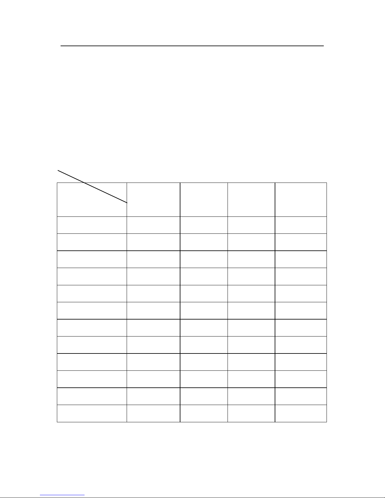
The micro steps setting is in thefollowingtable, whileSW3 、
SW4 、 SW5 、 SW6 are all on, the internal default micro steps inside is activate,
this ratio can be setting through the HISU.
Dial switch
Micro steps
SW3
SW4
SW5
SW6
Default
on
on
on
on
800
off
on
on
on
1600
on
off
on
on
3200
off
off
on
on
6400
on
on
off
on
12800
off
on
off
on
25600
on
off
off
on
51200
off
off
off
on
1000
on
on
on
off
2000
off
on
on
off
4000
on
off
on
off
5000
off
off
on
off
Page 14

-14-
8000
on
on
off
off
10000
off
on
off
off
20000
on
off
off
off
40000
off
off
off
off
7. Faults alarm and LED flickerfrequency
Flicker
Frequency
Description to the Faults
1
Error occurs when the motor coil current exceeds
the drive’s current limit.
2
Voltage reference error in the drive
3
Parameters upload error in the drive
4
Error occurs when the input voltage exceeds the
drive’s voltage limit.
5
Error occurs when the actual position following
error exceeds the limit which is set by the position
error limit.
0.8s
2s
Red Alarm LED Flash
Time Interval
Page 15
-15-
8. Appearance and InstallationDimensions
9. Typical Connection
This drive can provide the encoder with a power supply of +5v,
maximum current 80mA. It adopts a quadruplicated-frequency counting
method, and the resolution ratio of the encoder multiply 4 are the pulses
per rotate of the servo motor. Here is the typical connection of
44
142
612.8
53
4*¢
Hybrid Step Servo
142
150
26.
5
97.5
Page 16

-16-
2HSS86H-KH.
10. ParameterSetting
The parameter setting method of 2HSS86H-KH drive is to use a
HISU adjuster through the 232 serial communication ports, only in this
way can we setting the parameters we want. There are a set of best
defaultparameterstothecorrespondingmotorwhicharecarefully
VCC R PEND+
VCC R ALM+
Controller
ALM-
VCC
PUL+
270
PUL-
Pulse
Signal
DIR+
270
DIR-
Direction
Signal
ENA+
270
ENA-
Enable
Signal
Blue
PB+
Yellow
PA+
White
PB-
Green
PA-
Red
VCC
Blac k
GND
ECODER
2HSS86H-KH
Drive
Red
A+
M
Blue A-
Grenn
B+
Blac k
VAC
24~75V
B-
AC1
AC2
Page 17

-17-
adjusted by our engineers, users only need refer to the following table,
specific condition and set the correct parameters.
Actual value = Set value × the corresponding dimension
There are total 20 parameter configurations, use the HISU to download
the configured parameters to the drive, the detail descriptions to every
parameter configuration are asfollows:
Mode
Definition
Range
Dime-
nsion
Drive
Restart
Default
Value
P1
Current loop Kp
0—4000
1 N 1000
P2
Current loop Ki
0—1000
1 N 100
P3
Damping coefficient
0—1000
1 N 100
P4
Position loop Kp
0—4000
1 N 1300
P5
Position loop Ki
0—1000
1 N 250
P6
Speed loop Kp
0—3000
1 N 50
P7
Position loop Ki
0—1000
1 N 10
P8
Open loop current
0—60
0.1
N
45
P9
Close loop current
0—40
0.1
N
20
P10
Alarm level
0—1
1 N 0
P11
Reserved
P12
Stop lock enable
0—1
1 N 0
P13
Enable signal level
0—1
1 N 0
P14
Arrival level
0—1
1 N 1
P15
Encoder line number
0—1
1 Y 0
P16
Position error limit
0—3000
10
N
1000
P17
Reserved
P18
Motor type
0—5
0 Y 4
P19
Speed smoothness
0—10
1 N 0
P20
User-defined p/r
4-1000
50
Y
8
Page 18
-18-
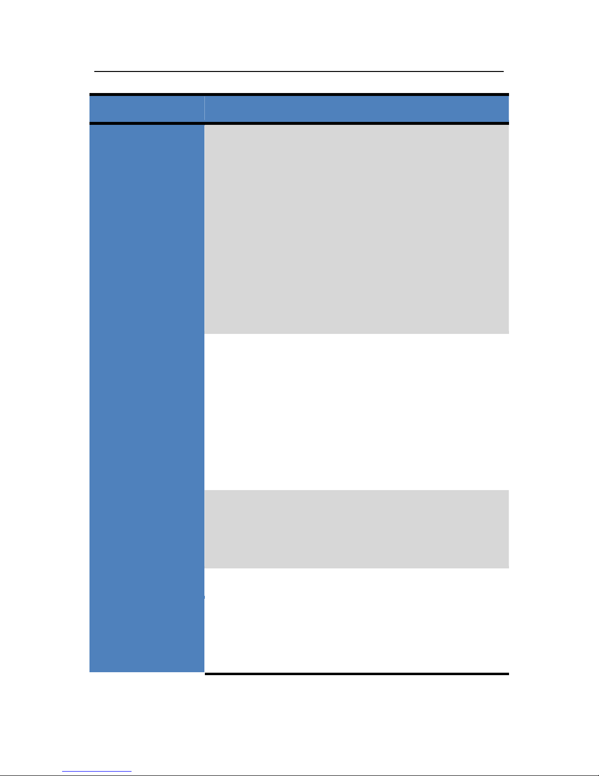
Item
Description
Current loop Kp
Increase Kp to make current rise fast. Proportional
Gain determines the response of the drive to setting
command. Low Proportional Gain provides a stable
system (doesn’t oscillate), has low stiffness, and the
current error, causing poor performances in tracking
current setting command in each step. Too large
proportional gain values will cause oscillations and
unstable system.
Current loop Ki
Adjust Ki to reduce the steady error. Integral Gain
helps the drive to overcome static current errors. A
low or zero value for Integral Gain may have current
errors at rest. Increasing the integral gain can reduce
the error. If the Integral Gain is too large, the system
may “hunt” (oscillate) around the desired position.
Damping
coefficient
This parameter is used to change the damping
coefficient in case of the desired operating state is
under resonance frequency.
Position loop Kp
The PI parameters of the position loop. The default
values are suitable for most of the application, you
don’t need to change them. Contact us if you have
any question.
Position loop Ki
Page 19
-19-
Speed loop Kp
The PI parameters of the speed loop. The default
values are suitable for most of the application, you
don’t need to change them. Contact us if you have
any question.
Speed loop Ki
Open loop
current
This parameter affects the static torque of the motor.
Close loop
current
This parameter affects the dynamic torque of the
motor. (The actual current = open loop current +
close loop current)
Alarm Control
This parameter is set to control the Alarm
optocoupler output transistor. 0 means the transistor
is cut off when the system is in normal working, but
when it comes to fault of the drive, the transistor
becomes conductive. 1 means opposite to 0.
Stop lock enable
This parameter is set to enable the stop clock of the
drive. 1 means enable this function while 0 means
disable it.
Enable Control
This parameter is set to control the Enable input
signal level, 0 means low, while 1 means high.
Arrival Control
This parameter is set to control the Arrival
optocoupler output transistor. 0 means the transistor
is cut off when the drive satisfies thearrival
Page 20
-20-
Encoder
resolution
Position error
limit
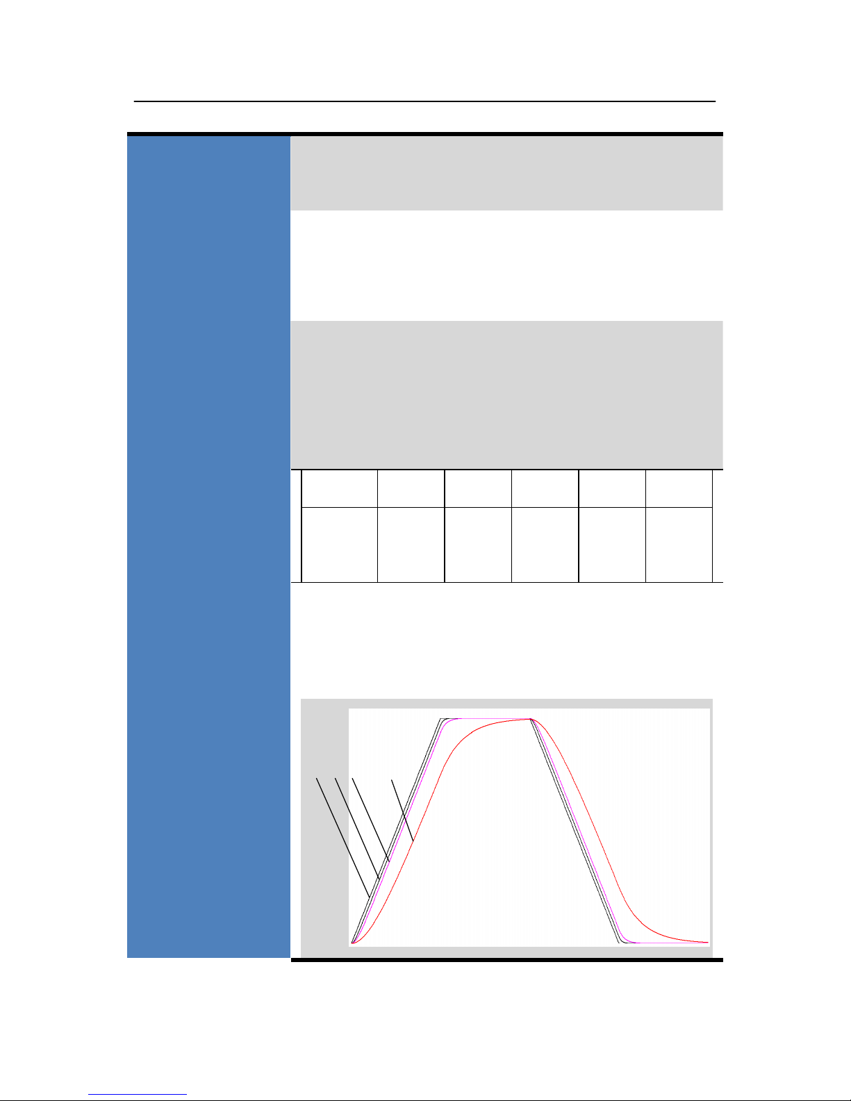
Motor
typeselection
Speed
smoothness
command, but when it comes to not, the transistor
becomes conductive. 1 means opposite to 0.
This drive provides two choices of the number of
lines of the encoder. 0 means 1000 lines, while 1
means 2500 lines.
The limit of the position following error. When the
actual position error exceeds this value, the drive
willgointoerrormodeandthefaultoutputwillbe
activated. (The actual value = the set value× 10)
Parameter
1 2 3 4 5
Type
86J18
65EC
86J18
80EC
86J18
95EC
86J18
118EC
86J18
156EC
This parameter is set to control the smoothness of
the speed of the motor while acceleration or
deceleration, the larger the value, the smoother the
speed in acceleration ordeceleration.
0
1 2 … 10
Page 21
-21-
User-defined p/r
This parameter is set of user-defined pulse per
revolution,theinternaldefaultmicrostepsinsideis
activatewhileSW3、SW4、SW5、SW6areallon,
users can also set the micro steps by the outer DIP
switches.(Theactualmicrosteps= the setvalue
× 50)
11. Processing Methods to Common Problems and
Faults
11.1 Power on power lightoff
No power input, please check the power supply circuit. The voltage
is toolow.
11.2 Power on red alarm lighton
Please check the motor feedback signal and if the motor is connected
with thedrive.
The stepper servo drive is over voltage or under voltage. Please
lower or increase the inputvoltage.
11.3 Red alarm light on after the motor running asmall
angle
Please check the motor phase wires if they are connected correctly,
if not, please refer to the 3.4 Power Ports.
Page 22

-22-
Please check the parameter in the drive if the poles of the motor and
the encoder lines are corresponding with the real parameters, if not,
set themcorrectly.
Please check if the frequency of the pulse signal is too fast, thus the
motor may be out of it rated speed, and lead to positionerror.
11.4 After input pulse signal but the motor notrunning
Please check the input pulse signal wires are connected in reliable
way.
Please make sure the input pulse mode is corresponding with the real
inputmode.
 Loading...