

Page 1
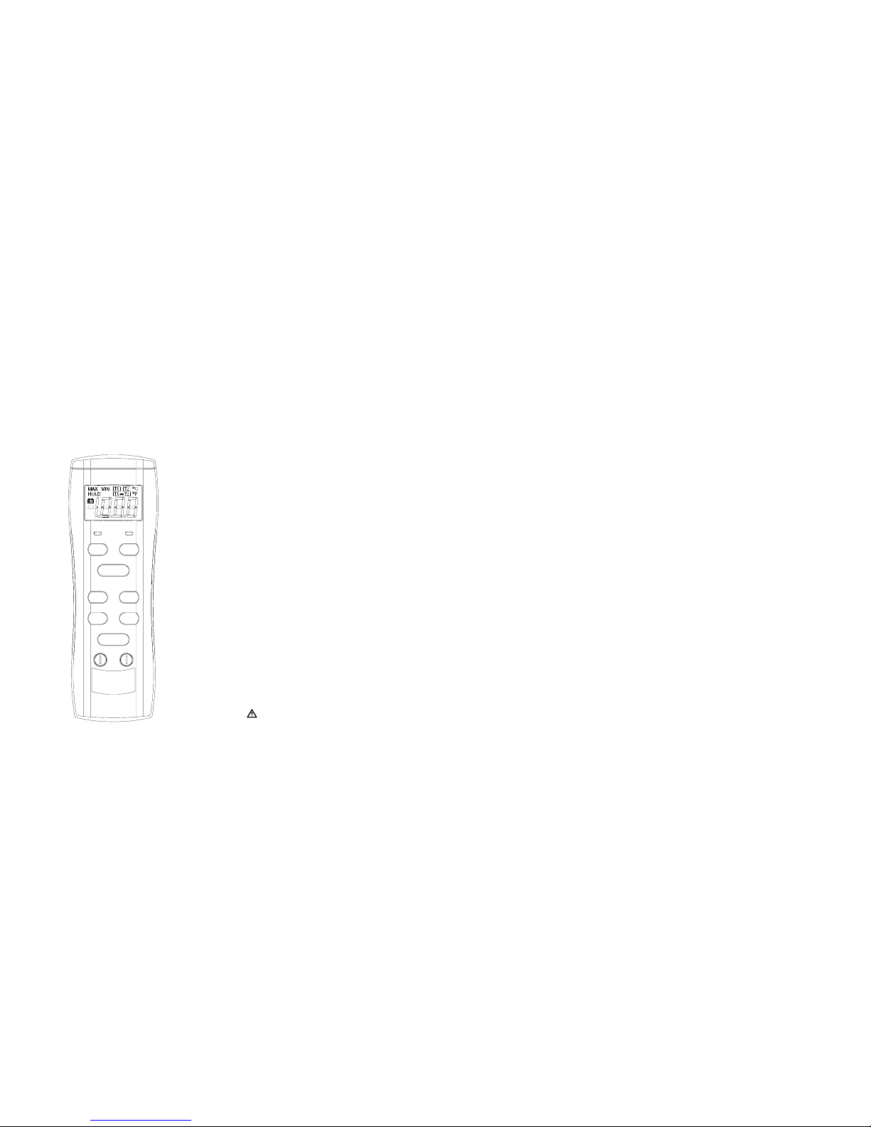
INTRODUCTION
This instrument is a portable 3½ digit, compact-sized
digital thermometer designed to use external K-type
thermocouple as temperature sensor. Temperature
indication follows National Bureau of Standards and
IEC 584 temperature/voltage tables for K-type
thermocouples. One K-type thermocouple is supplied with the thermometer.
SAFETY INFORMATION
It is recommended that you read the safety and operation instructions before using the thermometer.
Designed to meet IEC-1010-1, CE-EMC.
WARNING
TO AVOID ELECTRICAL SHOCK, DO NOT USE
THIS INSTRUMENT WHEN VOLTAGES AT THE
MEASUREMENT SURFACE EXCEED 24V AC OR
60V DC.
WARNING
TO AVOID DAMAGE OR BURNS, DO NOT MAKE
TEMPERATURE MEASUREMENTS IN MICROWAVE OVENS.
CAUTION
Repeated sharp flexing can break the thermocouple
leads. To prolong lead life, avoid sharp bends in the
leads, especially near the connector.
The symbol on the instrument indicates that the
operator must refer to an explanation in this manual.
SPECIFICATIONS
ELECTRICAL
Temperature Scale:
Celsius or Fahrenheit user-selectable
Measurement Range:
-50°C to 1300°C, ( -58°F to 2000°F )
Resolution: 1°C or 1°F, 0.1°C or 0.1°F
Accuracy:
Accuracy is specified for operating temperatures over the range
of 18°C to 28°C ( 64°F to 82°F ) , for 1 year,not including
thermocouple error.
±( 2°C ) -50°C to 0°C
±( 0.3% rdg + 1°C ) 0°C to 600°C
±( 0.5% rdg + 1°C ) 600°C to 1300°C
±( 4°F ) -58°F to 32°F
±( 0.3% rdg + 2°F ) 32°F to 1100°F
±( 0.5% rdg + 2°F ) 1100°F to 2000°F
Temperature Coefficient:
0.1x( specified accuracy ) per °C . ( 0°C to 18°C , 28°C to 50°C ).
Input Protection:
60V dc or 24V rms ac maximum input voltage on any combination of input pins.
Reading Rate:
2.5 times per second.
Input Connector:
Accepts standard miniature therm ocouple connectors ( flat
blades spaced 7.9mm , center to center ) .
ENVIRONMENTAL
Ambient Operation Range:
0°C to 50°C, (32°F to 122°F)
Storage Temperature:
-20°C to 60°C, (-4°F to 140°F)
Relative Humidity:
0% to 80% (0°C to 35°C) (32°F to 95°F)
0% to 70% (35°C to 50°C) (95°F to 122°F)
GENERAL
Display:
3½ digit liquid crystal display (LCD) with maximum reading of 1999
Battery:
Standard 9V battery (NEDA 1604,IEC 6F22)
Battery Life:
100 hours typical with carbon zinc battery
200 hours typical with alkaline battery
Dimensions: 184mm (H) x 62mm (W) x35mm (D)
Weight: 10.6oz (300g) including holster
Supplied Probe:
4-foot type “K” thermocouple bead probe (teflon
tape insulated). Maximum insulation temperature
260°C (500°F). Probe accuracy ±2.2°C or ±0.75%
of reading (whichever is greater) from 0° to 800°C.
OPERATING INSTRUCTIONS
DIGITAL THERMOMETER
T1 T2
T1-T2
ON OFF
C
°1°
0.1°/F
°
/
MIN
MAX/
HOLD
THERMOMETER
OFFSET
T1 T2
Page 2

OPERATING INSTRUCTIONS
Selecting the Temperature Scale
Readings are displayed in either degrees Celsius (°C)
or degrees Fahrenheit (°F). When the thermometer
is turned on, it is set to the temperature scale that was
in use when the thermometer was last turned off. To
change the temperature scale, press the °C or °F key.
Single-Thermocouple Temperature Measurement
The thermometer displays the temperature of the
thermocouple that is connected to the selected input.
Press the T2 key to display the temperature of the
thermocouple connected to the T2 input. Press the
T1 key to display the temperature of the themocouple
connected to the T1 input. The input selection cursor indicates which input is selected.
Differential Temperature Measurement
Differential temperature measurement is selected by
pressing the T1-T2 key. This causes the thermometer to display the temperature difference between
the two thermocouples ( the temperature of thermocouple T1 minus the temperature of thermocouple
T2 ). The selection is indicated by the input selection cursor.
Selecting the Display Resolution
The thermometer allows two choices of resolution:
High resolution: 0.1°C or 0.1°F
Low resolution: 1.0°C or 1.0°F
To select the alternate display resolution, press the
corresponding “1°” or “0.1°” key.
The 0.1° resolution is applicable for temperature
measurements below 200°C or 200°F.
HOLD Mode
Pressing the HOLD key to enter the Data Hold mode,
the “HOLD” annunciator is displayed. When HOLD
mode is selected, the thermometer holds the present
readings and stops all further measurements.
Pressing the HOLD key again cancels HOLD mode,
causing the thermometer to resume taking
measurements.
MIN/MAX Mode
Press MIN / MAX once to begin recording MIN and
MAX. Press MIN / MAX to select MIN or MAX.
Hold down for 2 seconds to exit MIN / MAX
function.
OFFSET ADJUSTMENT
The OFFSET control is set at the factory to allow for
the variations found in standard thermocouples. By
adjusting the OFFSET control, you can optimize
measurement accuracy for a particular thermocouple
at a particular temperature.
Adjusting for T1 or T2 Accurate Measurements
1.Connect the thermocouple to the T1 or T2 input
connector and turn the thermometer ON , then
press the 0.1° key to select the high display resolution. ( If using T2 , press the T2 key ).
2.Place the thermocouple in a known , stable temperature environment at or near the temperature
you wish to measure , and allow the readings to
stabilize.
3.Slowly adjust the OFFSET control so that the ther-
mometer reading matches the temperature of the
known environment. Leave sufficient time between adjustments to allow for measurement lag.
4.The calibration of the thermometer-thermocouple
combination is now optimized for measurements
near the temperature measured in step 2.
Resetting the OFFSET Control
To return the OFFSET control to the factory setting
without having to recalibrate the thermometer, perform the following procedure:
1.Connect a thermocouple that is in good working
order to the input that is to be adjusted.
2.Place the thermocouple in an ice-water bath and
allow the readings to stabilize.
3.Slowly adjust the OFFSET control until the thermometer reads 0°C ( 32°F )
Probe Detector
1.The red LED will be ON when no K-type thermocouple probe is inserted into the TEMP input of
the meter, and will be OFF after K-type thermocople probe is inserted. If the red LED stays ON
when thermocouple probe is attached, check the
thermocouple probe which might be damaged.
2.When T1 button is pressed, the T1 red LED will
be ON, and T2 red LED will be OFF.
When T2 button is pressed, the T2 red LED will
be ON, and T1 red LED will be OFF.
When T1-T2 button is pressed,both T1 and T2
red LEDs will be ON.
This is to advise the user to insert the thermocouple probes into the correct T1 and/or T2 TEMP
input jack where the red LED is ON.
OPERATOR MAINTENANCE
WARNING
TO AVOID POSSIBLE ELECTRICAL SHOCK,
DISCONNECT THE THERMOCOOUPLE
CONNECTORS FROM THE THERMOMETER
BEFORE REMOVING THE COVER.
Battery Replacement
Power is supplied by a standard 9 volt battery (NEDA
1604,IEC 6F22). The “ ” appears on the LCD display when replacement is needed. To replace the
battery, remove the screw from the battery cover of
the meter. Remove the battery and replace with a
new equivalent 9 volt battery.
P/N: 7000-1700
 Loading...