

Page 1
www.leadingtouch.com
1
/
27
Touchmonitor User Guide
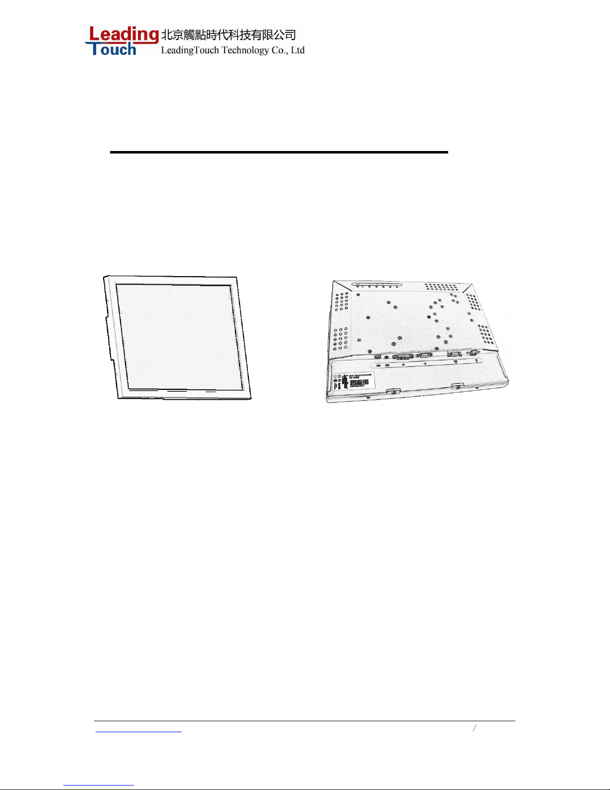
TM-19 19¨ LCD Rear Mount Touchmonitor
REV A
LeadingTouch Technology Co., Ltd
HuiLongGuan LongXiang industrial center,ChangPing,Beijing,China
Tel:+86-51090978 http://www.leadingtouch.com
Fax:+86-51090979 E-mail:[email protected]
Page 2

www.leadingtouch.com
2
/
27
INDEX
Chapter1 .............................................................................. 3
INTRODUCTION .................................................................3
Product Description........................................................3
Precautions ..................................................................3
About the Product..........................................................3
Chapter 2 ............................................................................. 5
INSTALLATION AND SETUP..................................................5
Unpacking Your Touchmonitor .........................................5
Touch Interface Connection.............................................6
Installing the Driver Software..........................................8
Chapter 3 ........................................................................... 15
OPERATION..................................................................... 15
About Touchmonitor Adjustments .................................. 15
Using the On-Screen Display (OSD) Menus ..................... 15
OSD Menu Function ..................................................... 16
Preset Modes.............................................................. 18
Power Management System.......................................... 18
Chapter 4 ........................................................................... 20
TROUBLESHOOTING......................................................... 20
Solutions to Common Problems..................................... 20
Appendix A......................................................................... 22
NA TIVE RESOLUTION........................................................ 22
Appendix B......................................................................... 24
TOUCHMONITOR SAFETY................................................... 24
Care and Handling of Your Touchmonitor......................... 24
Appendix C......................................................................... 26
TECHNICAL SPECIFICA T IONS............................................. 26
Compatible Video Modes............................................... 26
Page 3

www.leadingtouch.com
3
/
27
C H A P T E R
INTRODUCTION
Product Description
Congratulations on your purchase of a Leadingtouch touchmonitor. Your new touchmonitor
combines the reliable performance of Leadingtouch touch technology with the latest advances in LCD
display design. This combination of features creates a natural flow of information between a user and
your touchmonitor.
This LCD monitor incorporates a 19” color active matrix thin-film-transistor (TFT) to provide
superior display performance. A maximum resolution of SXGA
1280 x 1024 is ideal for displaying
graphics and images. Other outstanding features that enhance this LCD monitor’s performance are
Plug & Play compatibility, and OSD (On Screen Display) controls.
Precautions
Follow all warnings, precautions and maintenance as recommended in this user’s manual to maximize
the life of your unit. See Appendix B for more information on touchmonitor safety.
About the Product
Your LCD Desktop Touchmonitor is a 19.0” TFT color display with the following features:
• Direct analog RGB or Digital RGB input
• 19.0” diagonal screen size
• 16.7M color
• 1280 x 1024 resolution
• XGA/SVGA/VGA/VESA compatible
• 38.4-96.0 kHz horizontal scan
• Auto adjustment capability
• High quality full screen re-scaling
• Multilingual OSD menus in both languages: English,Chinese.
• Serial or USB touch interface (USB requires Windows 98, 2000, Me and XP.)
• Superior touch technology of Leadingtouch TouchSystems
• VESA flat panel monitor physical mounting interface (Both of 75 & 100mm)
Page 4

www.leadingtouch.com
4
/
27
• Wall mountable with optional bracket
• Cable strain reliefs for all cables
For full Product Specifications refer to Appendix C.
Page 5
www.leadingtouch.com
5
/
27
C H A P T E R
INSTALLATION AND SETUP
This chapter discusses how to install your LCD touchmonitor and how to install Leadingtouch
TouchSystems driver software.
Unpacking Your Touchmonitor
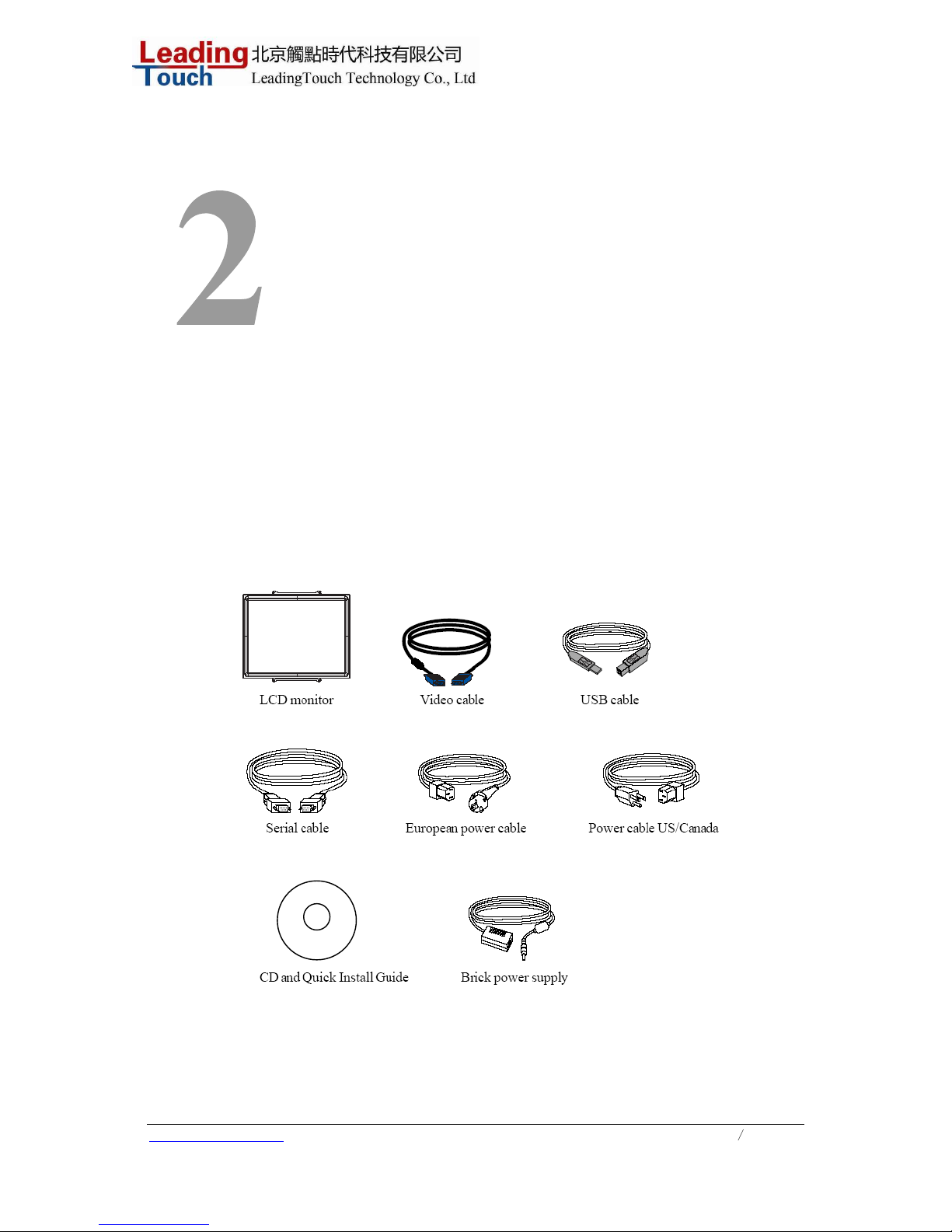
Check that the following 10 items are present and in good condition:
or
Page 6
www.leadingtouch.com
6
/
27
Touch Interface Connection
Note: Before connecting the cables to your touchmonitor and PC, be sure that the computer
and
touchmonitor are turned off.
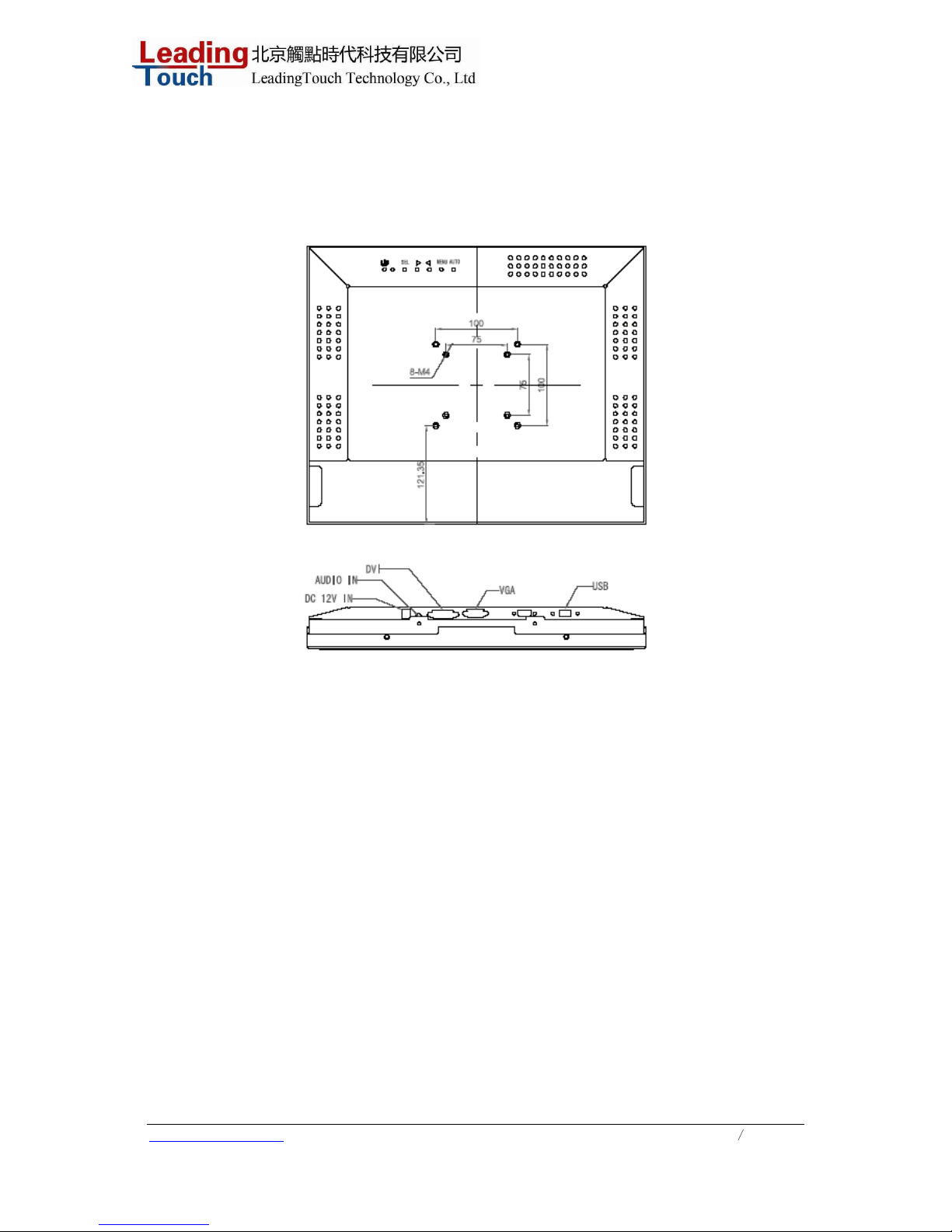
1. Connect one end of the power adapter to the monitor and the other end to the connector of the
power cord.
2. Connect one end of either the touchscreen serial (RS232) cable or the touchscreen USB cable
(but not both) to the rear side of the computer and the other end to the LCD monitor. Tighten by
turning the two thumb screws clockwise to ensure proper grounding (optional module USB cable
does not have thumb screws).
3. Connect one end of the video cable to the rear side of computer and the other to the LCD monitor.
Tighten by turning the two thumb screws clockwise to ensure proper grounding.
4. Press the power button on back frame to turn the monitor power on.
Page 7
www.leadingtouch.com
7
/
27
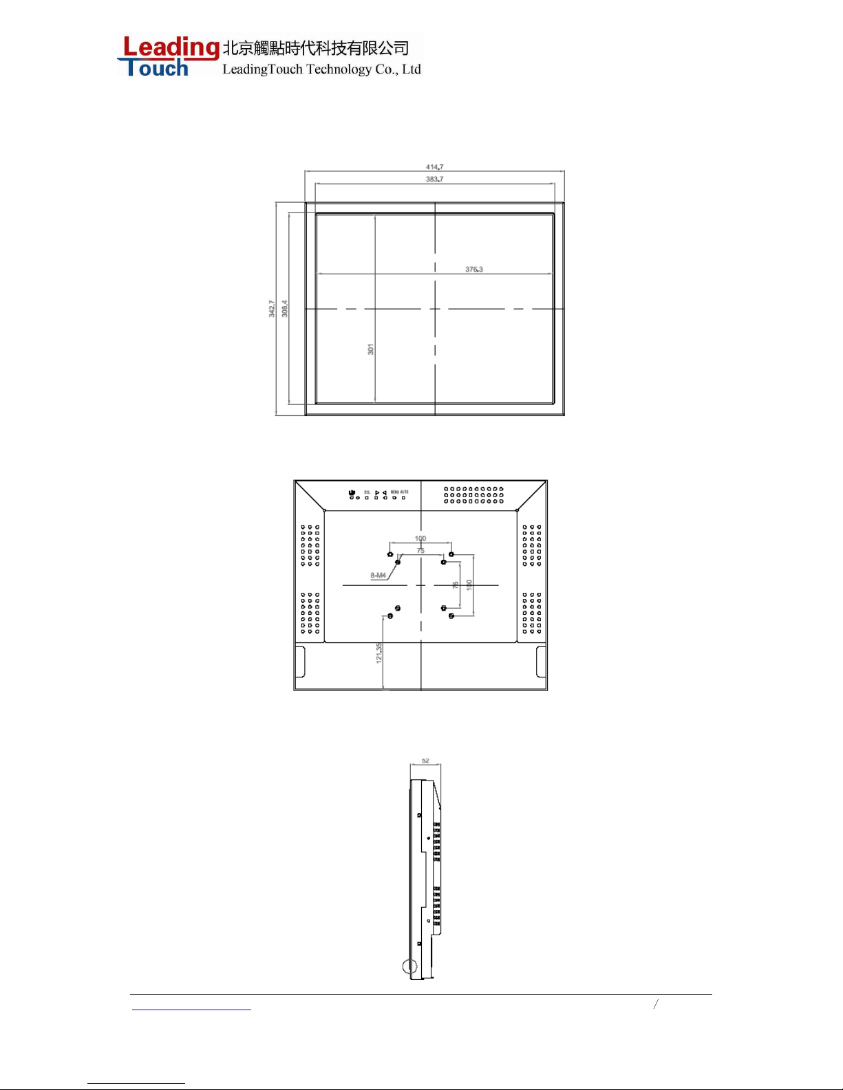
Product Overview
Main Unit
Rear View
Side View
Page 8
www.leadingtouch.com
8
/
27
Installing the Driver Software
Leadingtouch TouchSystems provides driver software that allows your touchmonitor to work with your
computer. Drivers are located on the enclosed CD-ROM for the following operating systems:
• Windows XP
• Windows 2000
• Windows Me
• Windows 98
• Windows 95
• Windows NT 4.0
Additional drivers and driver information for other operating systems are available on the
Leadingtouch web site at www.Leadingtouch.com.
Your Leadingtouch touchmonitor is plug-and-play compliant. Information on the video capabilities of
yourtouchmonitor is sent to your video display adapter when Windows starts. If Windows detects your
touchmonitor, follow the instructions on the screen to install a generic plug-and-play monitor.
Refer to the appropriate section for driver installation instructions.
Depending upon whether you connected the serial communication cable or the USB
communication cable, you should install only the serial driver or the USB driver.
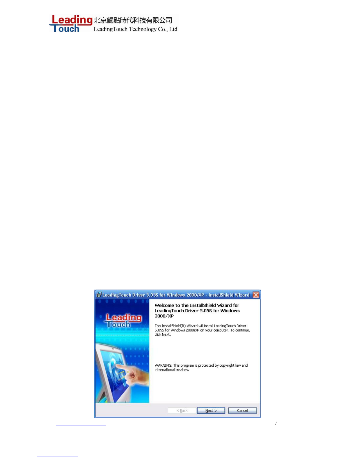
1.1 Installing and Using Leadingtouch for Windows Serials
Leadingtouch is software, which contains drivers of the touch panel controllers for the
specified communication connectors, RS232, USB
Follow these steps to install Leadingtouch .
1. Put the Leadingtouch CD to CD-ROM.
2. Change directory to Win9598me OR Win2000_XP.
3. Double click the Setup.exe, then windows starts to run the installation program.
4. Just click [Next >] button to continue installation.
Page 9
www.leadingtouch.com
9
/
27
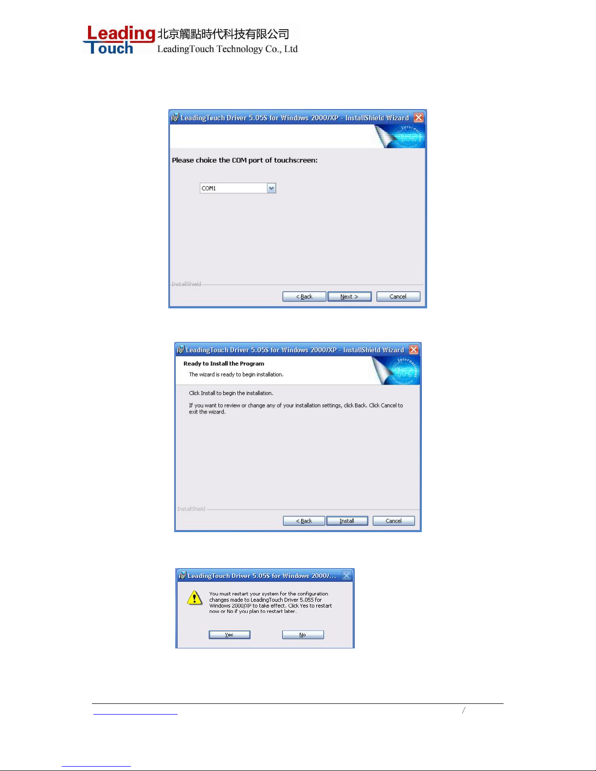
5. Click “Next>”,and select the com port which the touchscreen connected.
6. Then press [Install >] to continue installation.
7. After install finished,you need restart the system and save all your working files
Page 10
www.leadingtouch.com
10
/
27
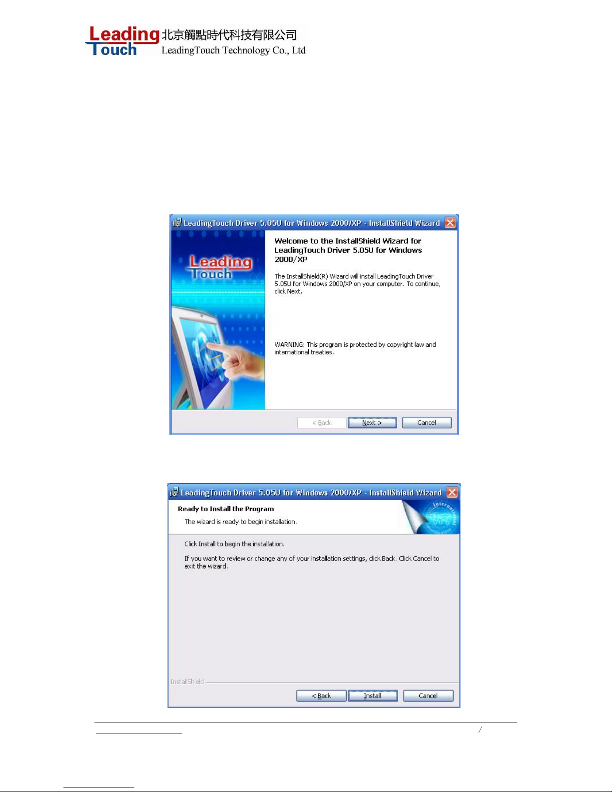
1.2 Installing and Using Leadingtouch for Windows Usb
Leadingtouch is software, which contains drivers of the touch panel controllers for the
specified communication connectors, RS232, USB
Follow these steps to install Leadingtouch .
1. Put the Leadingtouch CD to CD-ROM.
2. Change directory to Win9598me OR Win2000_XP.
3. Double click the Setup.exe, then windows starts to run the installation program.
4. Just click [Next >] button to continue installation.
5. Then press [Install >] to continue installation.
Page 11
www.leadingtouch.com
11
/
27
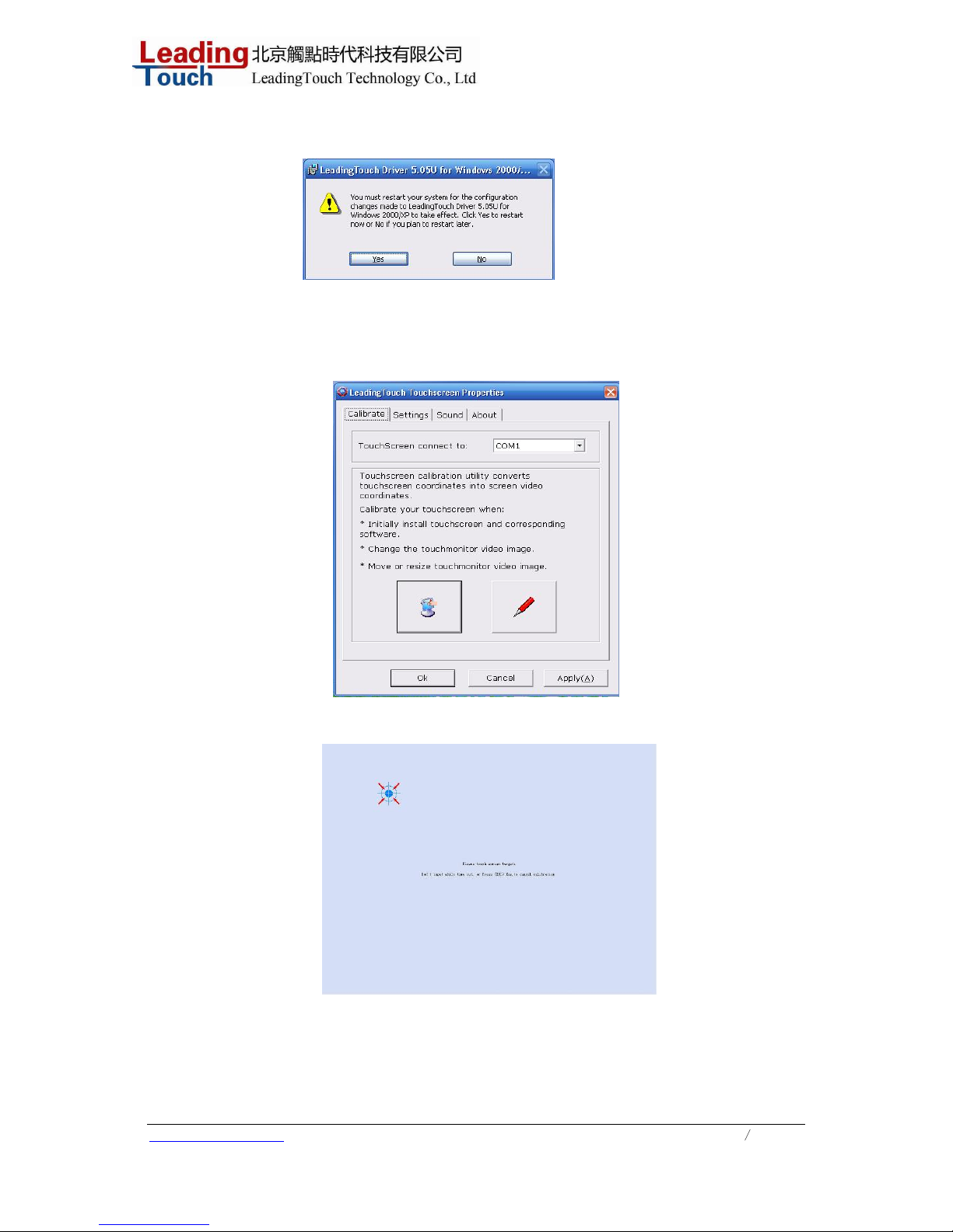
6 After install finished,you need restart the system and save all your working files
1.3 Calibration and test mode
1)After successful installtion of the drver,reboot the system first.adn then click “calibrate”
2)Click the center of the bull’s eyes cross with finger according to the prompt
3) click all the bull’s eyes,press “Enter”or double click the touchscreen to save the calibration
data.
Notice:Re-calibrate is required if the follo wing changes occur:
1 Change of monitor’s resolution
Page 12
www.leadingtouch.com
12
/
27
2 Change of touchscreen
3 Change of computer or monitor
Enter Touchscreen calibration program through the following programmer
1 Click “Start”----“programmer”----“Leadingtouch”--------“Serial/USB”
2 Click “Calibration”
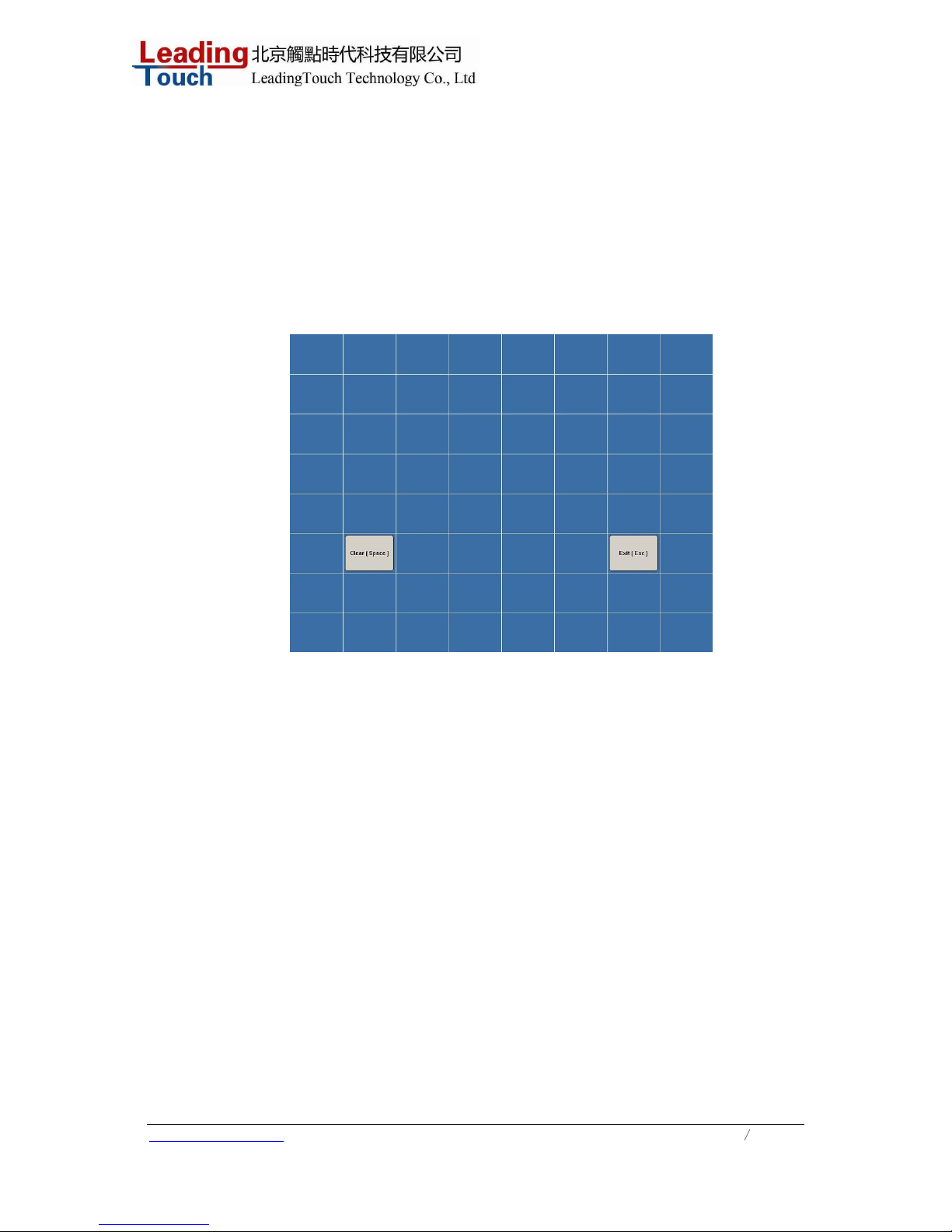
1.3 Line test
Test the touchscreen.
1 Clear------clear all the lines in the test screen.
2 Exit -------quit test mode.
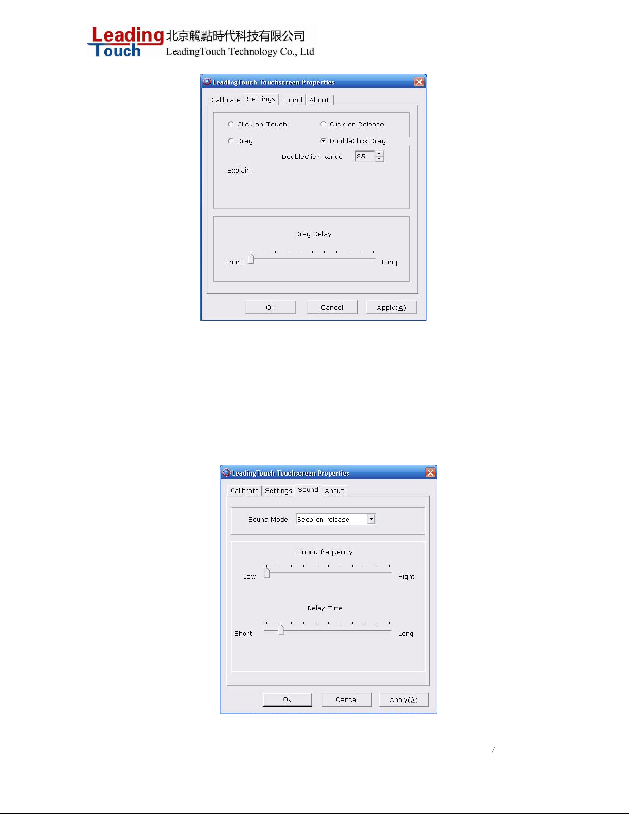
1.4 Setup of the Touchscreen Paramter
Click “Touchsetup”in Leadingtouch,Working mode of the touchscreen can be modified on
“Settings” lables
Page 13
www.leadingtouch.com
13
/
27
Working Mode(mouse emulation mode)
Click on touch indicates the response when your finger touches on the panel
Click on release indicates the response when your finger leavvs the touchs panel
Drag line mode
DoubleClick,Drag support double click and drag mode,double click range indicates the
double click area,the unit is pixel
Drag Delay Time delay of the dragging
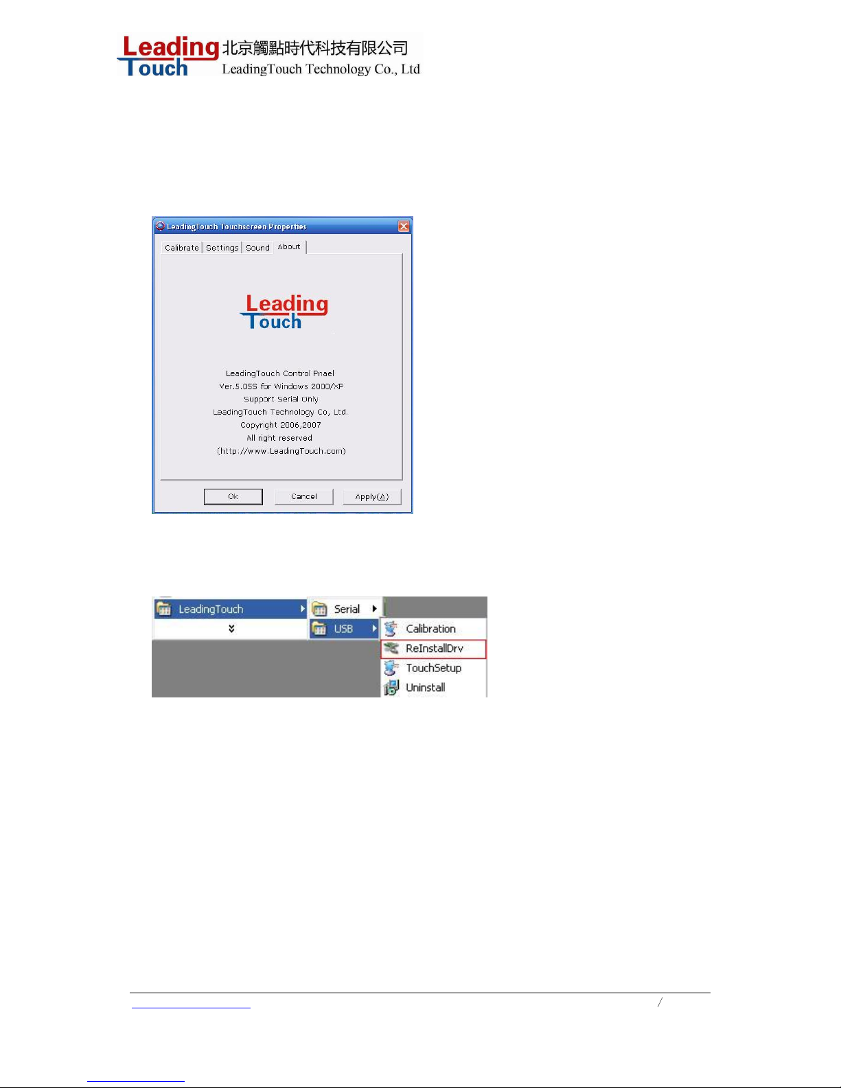
1.5 Sound
Beep on touch the speaker on the computer will generate voice when touch on the touchscreen
Page 14
www.leadingtouch.com
14
/
27
Beep on release the speaker on the computer will generate voice when leave of the touchscreen
Disable no voice when touch
1.6 About
About leadingtouch
1.7 Rescan Leadingtouch usb controller
After you replus Leadingtouch usb touchscreen controller,please use this tools
rescan the touchscreen
1.8 Uninstall Leadingtouch drivers
Enter Touchscreen Uninstall program through the following programmer
1 Click “Start”----“programmer”----“Leadingtouch”--------“Serial/USB”
2 Click “Uninstall”
Page 15
www.leadingtouch.com
15
/
27
C H A P T E R
OPERATION
About Touchmonitor Adjustments
Your touchmonitor will unlikely require adjustment. Variations in video output and application may
require adjustments to your touchmonitor to optimize the quality of the display.
For best performance, your touchmonitor should be operating in native resolution, that is 1280 x 1024.
Use the Display control panel in Windows to choose 1280 x 1024 reso lution.
Operating in other resolutions will degrade video performance. For further information, please refer to
Appendix A.
All adjustments you make to the controls are automatically memorized. This feature saves you from
having to reset your choices every time you unplug or power your touchmonitor off and on. If there is a
power failure your touchmonitor settings will not default to the factory specifications.
OSD Controls
Using the On-Screen Display (OSD) Menus
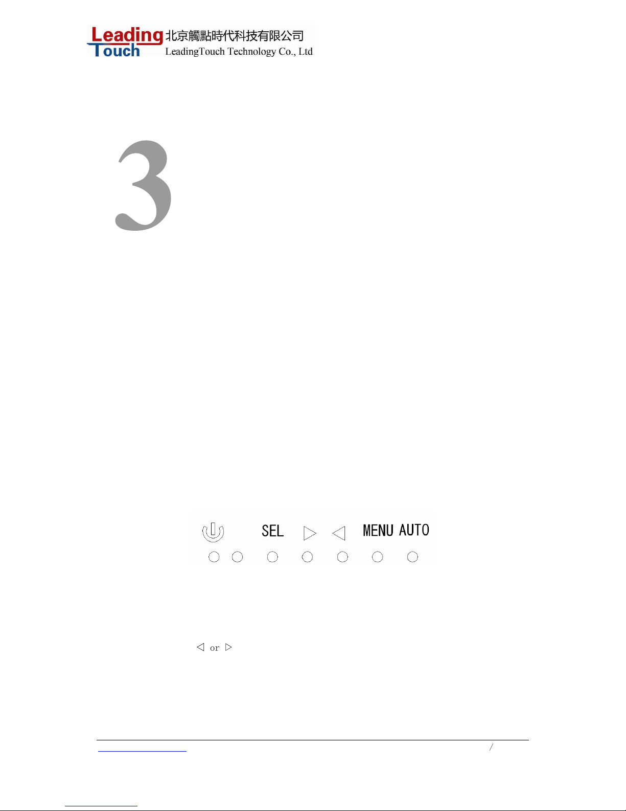
All adjustments are made by using the on-screen display (OSD) menus. All menu items can be selected
by using the buttons
△
or
▽
Page 16
www.leadingtouch.com
16/27
NOTE: OSD menu default is enabled.
Control Function
1 Menu/Exit Display/exits the OSD menus.
2
▽
1. Enter contrast of the OSD.
2. Increase value of the adjustment item.
3. Select item counter-clockwise.
3
△
1. Enter brightness adjustment.
2. Decrease value of the adjustment item.
3. Select item counter-clockwise.
4 Select Selects the adjustment items from the OSD menus.
5 Power Switch Switches the power of the monitor.
1
OSD Menu Function
To Display and Select the OSD Functions:
1 Press the Menu key to activate the OSD menu.
2 Use
△
or
▽
to move counter-clockwise through the menu. Press the Enter key, the parameter
will be highlighted when selected.
3 To quit the OSD screen at any time during the operation, pr ess the Menu key. If no keys are
pressed for a short time period, the OSD automatically disappears.
NOTE: The OSD screen will disappear if no input activities are detected for 45 seconds.
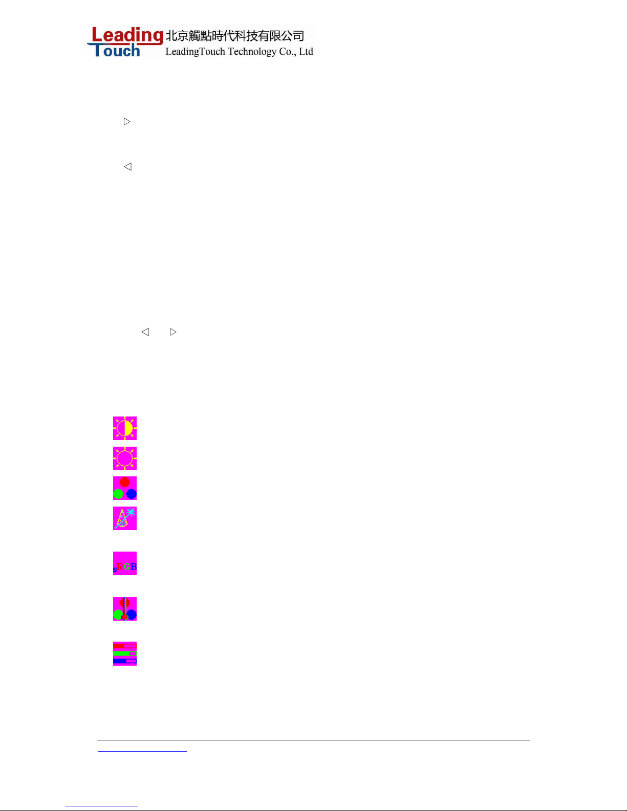
Control Description
Contrast Increases or decreases contrast
Brightness Increases or decreases brightness
Color): RGB color adjustment
Auto color) Automatically adjust RGB color.
sRGB: Select sRGB standard color
Color Temperature In this menu you can select one of the default color temperatures
(9300
oK, 7500oK, 6500oK, 5000oK, 4200oK )
User Press the OSD button Up and Down or set color values
individually using the "USER" option. To define the color values
individually, select the "USER" option. You can switch between
the setting options for R/G/B (red, green and blue foreground)
using the OSD direction button. Select and specify the desired
Page 17
www.leadingtouch.com
17/27
value by using the OSD button.
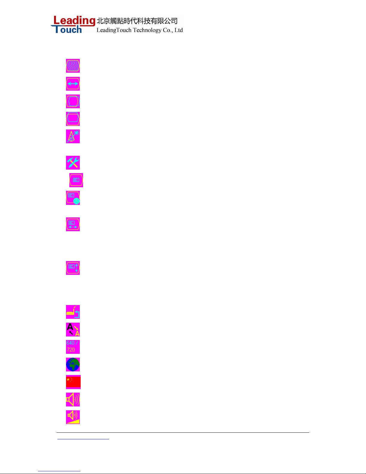
Phase) Controls the vertical and horizontal fine tuning.
Width Adjusts screen width
H-Position Moves the screen left or right
V-Position Moves the screen up or down.
Auto Adjust Automatically selects t he optional settings for image p arameters (brightness,
contrast, image position, phase etc).Display the current graphic mode.
Tools Enter to adjust OSD, Reset, sharpness, dos or language
OSD OSD parameter adjustment
OSD Time Determines how long (in seconds) the OSD menu waits before
closing automatically after no action has been perform e d.
OSD H-Position Moves the OSD position horizontally on the screen. When the button
is pressed, the OSD control menu will move to the right side of the
screen. Likewise, when the button is pressed, the OSD control menu
will move to the left side.
OSD V-Position Moves the OSD position vertically on the screen. When the button is
pressed, the OSD control menu will move to the top side of the screen.
Likewise, when the button is pressed, the OSD control menu will move
to the lower side.
Reset Reset factory settings of the image parameters.
Sharpness The sharpness can be adjustable.
DOS Adjusts screen position under dos
Language Selection of the OSD menu language: English, Chinese
Chinese Selection of the OSD menu language as Chinese
Audio Selection of speaker mode
Volume Selection of speaker volume
Page 18
www.leadingtouch.com
18/27
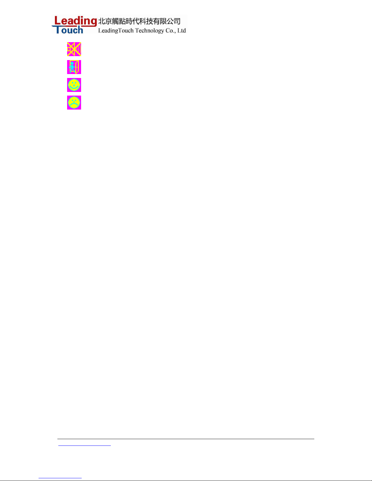
Mute Selection of speaker mute mode
Exit Exit the menu.
OK/Yes Confirmation of a right operation
Error/No Reminder of a wrong setting
Preset Modes
To reduce the need for adjustment for different modes, the monitor has default setting modes that
are most commonly used as given in the table below. If any of these display modes are detected, the
monitor automatically adjusts the picture size and centering. When none of the mode is matched,
the user can store their preferred modes in the user modes. The monitor is capable of storing up to
7 user modes. The only condition to store as a user mode is the new display information must have
1 KHz difference for horizontal frequency or 1 Hz for vertical frequency or the sync signal
polarities are different from the default modes.
Default modes is as following:
VGA
640 x 48 0 -- 60 Hz
640 x 48 0 -- 72 Hz
640 x 480 -- 75 Hz
640 x 35 0 -- 70 Hz
720 x 40 0 -- 70 Hz
SVGA
800 x 60 0 -- 56 Hz
800 x 60 0 -- 60 Hz
800 x 600 -- 72 Hz
800 x 60 0 -- 75 Hz
XGA
1024 x 768 -- 60 Hz
1024 x 768 -- 70 Hz
1024 x 768 -- 75 Hz
1024 x 768 -- 72 Hz
SXGA
128 0 x 1024 -- 60 Hz
128 0 x 1024 -- 70 Hz
128 0 x 1024 -- 75 Hz
Power Management System
The monitor is equipped with the power management function which automatically reduces the power
consumption when not in use.
Page 19

www.leadingtouch.com
19/27
Mode PowerConsumption
On <30W
Sleep <4W
Off <2W
We recommend switching the monitor off when it is not in use for a long time.
NOTE: The monitor automatically goes through the Power Management System (PMS) steps
when it is idle. To activate the monitor, press any key on the keyboard or move the mouse.
Check the cable connections. Make sure all the cables are connected correctly. Including a
female F Type connector(ANT IN) for VHF/UHF antenna input, a female F Type(MD OUTPUT)
with user-selectable channel 3 or 4NTSC RF output to analog television receiver, female RCA
connectors for stereo left and right audio (white and red) and a female RCA connector for
composite video (yellow). Then insert the adapter whose output plug is into the STB’s DC
socket and the input plug is into the power socket. Put switch which is in the power socket on,
Turn on the television and switch to video mode.
Then Power System will work, and low voltage transformer will supply power to Control
System, ATSC Tuner and Modulator, and the LED Indicator state is red, meaning the STB
state is stand-by. When you turn the stand-by to power state by Remote Control or the press
button on the top of cover, then the LED Indicator state is green and STB is Power State. So
ATSC Tuner can receive VHF or UHF frequency signal and transfer it to low frequency signal,
then Demodulator demodulate the low frequency signal and output the Transfer Stream(TS) to
Decode System, Control System separate the program stream (PS) which come from Decode
System into Video PID and Audio PID, and then Audio Decoder and Video Decoder decode
them separately and output the digital video signal and analog signal is amplified by amplifier
and output to television. Also the digital video signal is converted to analog video signal by
NTSC Encoder and DAC and then output to television.
So you can see the picture and hear the sound in television with the program you select, If
there is no any program stored in the STB, or you want to add new program to program list,
you need to search program by Remote Control, the IR receiver receive the Infra-red which
come from Remote Control and encode it, Control System receive and deal the encoded
signal. If you have connected the STB to analog television receiver with RF cable, you also
can watch television, because the RF signal is modulate by Modulator and the RF output
channel is control by software, you can change it by Remote Control.
This STB provide the capability to automatically switch from Power state to the
Sleep(Stand-by) state after a period of time without user input, and the default period of
inactivity before the equipment automatically switches to the Sleep(Stand-by) state is four
hours. Also you can select the pre-set period of time or turn off this function by Remote Control
in Power sate.
Page 20

www.leadingtouch.com
20/27
C H A P T E R
TROUBLESHOOTING
If you are experiencing trouble with your touchmonitor, refer to the following table. If the problem
persists, please contact your local dealer or our service center.
Solutions to Common Problems
Problem Suggestion(s)
No image appears on screen.
Check that all the I/O and power connectors are properly connected as described in Chapter 2. Make
sure the pins of the connectors are not crooked or broken. Test power supply by trying different cables,
a different wall outlet or plug another appliance into the outlet. Make certain the video cable is properly
connected and that it is not damaged. Check for bent pins on the cable connectors. Ensure that your
computer and video card are properly configured. (Consult video card documentation.) “Out of Range”
display Check to see if the resolution of your computer is higher than that of the LCD display.
Reconfigure the resolution of your computer to make it less than or equal to 1280 x 1024. See
Appendix A for more informati on on resol ut ion.
OSD/Power buttons don't respond
See page 3-21 for OSD enable/disable.
Image has vertical flickering line bars.
Use “Phase” to make an adjustment.
Check and reconfigure the display mode of the vertical refresh rate of your graphic card to make it
compatible with the LCD display.
Image is unstable and flickering
Use “CLOCK” to make an adjustment.
Image is scrolling
Make sure the VGA signal cable (or adapter) is well connected.
Page 21

www.leadingtouch.com
21/27
Check and reconfigure the display mode of the vertical refresh rate of your graphic card to make it
compatible with the LCD display.
Touch doesn’t work
Make sure cable is securely attached at both ends.
Page 22

www.leadingtouch.com
22/27
A P P E N D I X
NATIVE RESOLUTION
The native resolution of a monitor is the resolution level at which the LCD panel is designed to
perform best. For the Leadingtouch LCD touchmonitor, the native resolution is 1280 x 1024 for the 19
inch size.
In almost all cases, screen images look best when viewed at their native resolution. You can lower the
resolution setting of a monitor but not increase it.
Input Video 19" LCD
640 x 480 (VGA) Transforms input format to 1280 x 1024
800 x 600 (SVGA) Transforms input format to 1280 x 1024
1280 x 1024 (XGA) Displays in Native Resolution
The native resolution of an LCD is the actual number of pixels horizontally in the LCD by the
number of pixels vertically in the LCD. LCD resolution is usually represented by the following
symbols:
VGA
640 x 48 0 -- 60 Hz
640 x 48 0 -- 72 Hz
640 x 480 -- 75 Hz
640 x 35 0 -- 70 Hz
720 x 40 0 -- 70 Hz
SVGA
800 x 60 0 -- 56 Hz
800 x 60 0 -- 60 Hz
800 x 600 -- 72 Hz
800 x 60 0 -- 75 Hz
XGA
1024 x 768 -- 60 Hz
1024 x 768 -- 70 Hz
1024 x 768 -- 75 Hz
1024 x 768 -- 72 Hz
Page 23

www.leadingtouch.com
23/27
SXGA
128 0 x 1024 -- 60 Hz
128 0 x 1024 -- 70 Hz
128 0 x 1024 -- 75 Hz
As an example, a SVGA resolution LCD panel has 800 pixels horizontally by 600 pixels vertically.
Input video is also represented by the same terms. XGA input video has a format of 1280 pixels
horizontally by 1024 pixels vertically. When the input pixels contained in the video input format match
the native resolution of the panel, there is a one to one correspondence of mapping of input video pixels
to LCD pixels. As an example, the pixel in column 45 and row 26 of the input video is in column 45
and row 26 of the LCD. For the case when the input video is at a lower resolution than the native
resolution of the LCD, the direct correspondence between the video pixels and the LCD pixels is lost.
The LCD controller can compute the correspondence between video pixels and LCD pixels using
algorithms contained on its controller. The accuracy of the algorithms determines the fidelity of
conversion of video pixels to LCD pixels. Poor fidelity conversion can result in artifacts in the LCD
displayed image such as varying width characters.
Page 24

www.leadingtouch.com
24/27
A P P E N D I X
TOUCHMONITOR SAFETY
This manual contains information that is important for the proper setup and maintenance of your
touchmonitor. Before setting up and powering on your new touchmonitor, read through this manual,
especially Chapter 2 (Installation), and Chapter 3 (Operation).
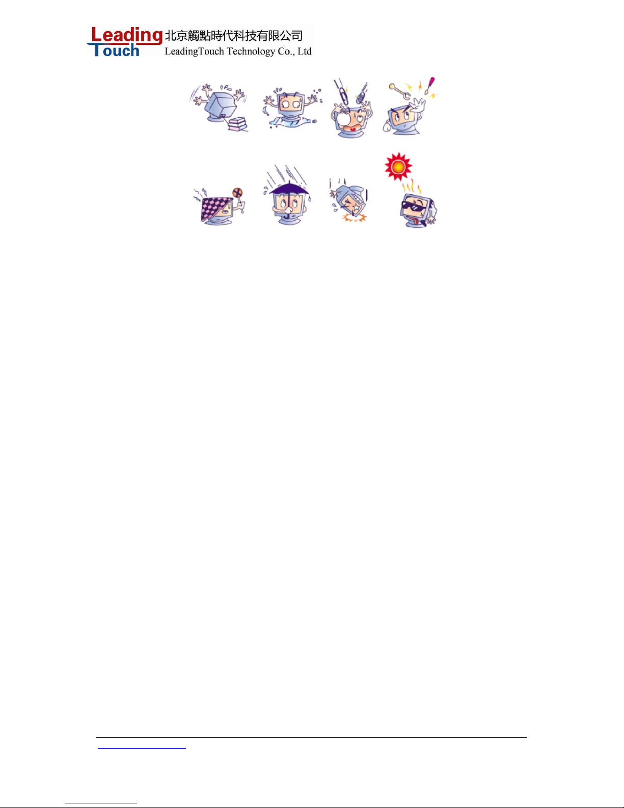
1. To reduce the risk of electric shock, follow all safety notices and never open the touchmonitor case.
2 Turn off the product before cleaning
3 Your new touchmonitor is equipped with a 3-wire, grounding power cord. The power cord plug will
only fit into a grounded outlet. Do not attempt to fit the plug into an outlet that has not been configured
for this purpose. Do not use a damaged power cord. Use only the power cord that comes with your
Leadingtouch TouchSystems Touchmonitor. Use of an unauthorized power cord may invalidate your
warranty.
4 The slots located on the sides and top of the touchmonitor case are for ventilation. Do not block or
insert anything inside the ventilation slots.
5 It is important that your touchmonitor remains dry. Do not pour liquid into or onto your touchmonitor.
If your touchmonitor becomes wet do not attempt to repair it yourself.
Care and Handling of Your Touchmonitor
The following tips will help keep your touchmonitor functioning at the optimal level.
• To avoid risk of electric shock, do not disassemble the brick supply or display unit cabinet. The unit
is not user serviceable. Remember to unplug the display unit from the power outlet before cleaning.
• Do not use alcohol (methyl, ethyl or isopropyl) or any strong dissolvent. Do not use thinner or
benzene, abrasive cleaners or compressed air.
• To clean the display unit cabinet, use a cloth lightly dampened with a mild detergen t.
• Avoid getting liquids inside your touchmonitor. If liquid does get inside, have a qualified service
technician check it before you power it on again.
• Do not wipe the screen with a cloth or sponge that could scratch the surface.
• To clean the touchscreen, use window or glass cleaner. Put the cleaner on the rag and wipe the
touchscreen. Never apply the cleaner directly on the touchscreen
Page 25
www.leadingtouch.com
25/27
Page 26

www.leadingtouch.com
26/27
A P P E N D I X
TECHNICAL SPECIFICATIONS
Compatible Video Modes
Your touchmonitor is compatible with the following standard video modes:
VGA
640 x 48 0 -- 60 Hz
640 x 48 0 -- 72 Hz
640 x 480 -- 75 Hz
640 x 35 0 -- 70 Hz
720 x 40 0 -- 70 Hz
SVGA
800 x 60 0 -- 56 Hz
800 x 60 0 -- 60 Hz
800 x 600 -- 72 Hz
800 x 60 0 -- 75 Hz
XGA
1024 x 768 -- 60 Hz
1024 x 768 -- 70 Hz
1024 x 768 -- 75 Hz
1024 x 768 -- 72 Hz
SXGA
128 0 x 1024 -- 60 Hz
128 0 x 1024 -- 70 Hz
128 0 x 1024 -- 75 Hz
Page 27

www.leadingtouch.com
27/27
Warning statement
Changes or modifications to this unit not expressly approved by the party responsible
for compliance could void the user authority to operate the equipment .
NOTE: This equipment has been tested and found to comply with the limits for a
Class B digital device, pursuant to Part 15 of the FCC Rules.These limits are designed
to provide reasonable protection against harmful interference in a residential
installation. This equipment generates,uses and can radiate radio frequency energy
and, if not installed and used in accordance with the instructions, may cause harmful
interference to radio communications. However, there is no guarantee that
interference will not occur in a particular installation.
If this equipment does cause harmful interference to radio or television reception,
which can be determined by turning the equipment off and on, the user is encouraged
to try to correct the interference by one or more of the following measures:
-- Reorient or relocate the receiving antenna.
-- Increase the separation between the equipment and receiver.
-- Connect the equipment into an outlet on a circuit different
from that to which the receiver is connected.
-- Consult the dealer or an experienced radio/TV technician for help.
 Loading...