

Leading Edge 5630-1RDP Assembly Instructions Manual
ASSEMBLY INSTRUCTIONS & PARTS MANUAL FOR
REVERSIBLE CEILING FANS
CEILING FANS SHOULD BE INSTALLED
BY QUALIFIED INSTALLER.
SPECIFICATIONS
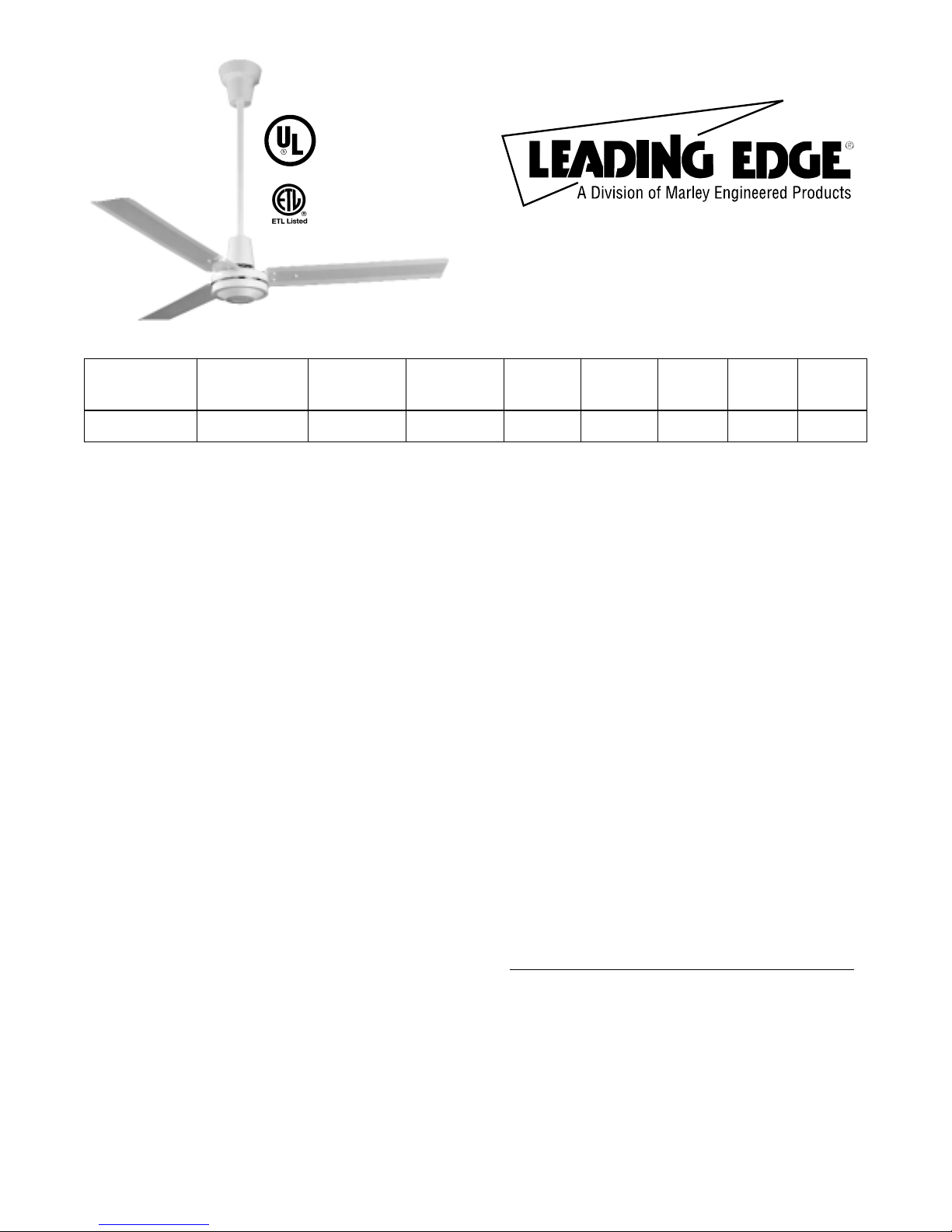
MODEL: 5630-1RDP
MODEL
NUMBER
BLADE
SWEEP COLOR VOLTAGE
MAX
HZ
MAX
RPM
MAX
AMPS WATTSWT(LBS)
5630-1RDP 56” White 120 50/60 275 1.0 110 24
READ INSTRUCTIONS CAREFULLY BEFORE ATTEMPTING TO ASSEMBLE OR SERVICE THE LEADING EDGE
CEILING FAN. FAILURE TO COMPLY WITH INSTRUCTIONS COULD RESULT IN PERSONAL INJURY AND/OR
PROPERTY DAMAGE.
RETAIN FOR FUTURE REFERENCE.
General Safety Information
WARNING: DISCONNECT POWER BEFORE
INSTALLING OR SERVICING THIS EQUIPMENT.
1. All electrical wiring should be done by a qualified
electrician in accordance with applicable National
Electrical Code and local electrical codes.
2. Do not allow moving blades to come in contact with
any part of the body.
3. Mount fan so that fan blades are 10 feet or higher
from floor.
4. Make sure hanger hooks are mounted securely to
structural ceiling members.
5. Do not mount in an area which will allow the fan to
get wet.
WARNING: DO NOT USE IN AN EXPLOSIVE
ATMOSPHERE.
6. Make certain that the ground wire is connected to
the ground terminal and to a suitable electrical
ground.
NOTE: When mounted in cathedral ceilings, the blade tip
should be at least 12 inches from the angled roof line to
prevent air “blow back” causing possible fan sway.
CAUTION: Read and follow instructions carefully.
Failure to comply with instructions could result in
the risk of fire, shock, and injury to persons.
WARNING:TO REDUCE THE RISK OF PERSONAL
INJURY DO NOT BEND THE BLADE BRACKETS
WHEN INSTALLING THE BRACKETS OR CLEANING
THE FAN. DO NOT INSERT FOREIGN OBJECTS IN
BETWEEN ROTATING FAN BLADES.
Description
Leading Edge Fans are designed as a dual purpose
product. By minimizing temperature stratification in
winter, they can reduce heating costs in high bay
buildings. The summertime application provides a gentle
downward movement of air for general air recirculation
and evaporative cooling. A permanent split capacitor
motor and permanently lubricated ball bearings add to
the efficiency and quietness of the fans.
Unpacking
1. Remove fan components from carton carefully.
2. Check for shipping damage.
3. Check for missing parts against parts list.
RECOMMENDED MOUNTING HEIGHTS
For heat reclamation, this fan should be mounted on the
standard 2’ downrod included. On installations through
drop ceilings, note the diameter of the downrod hole in
the ceiling should be 2
1
/2”.
CAUTION: Fan blades should not be mounted lower
than 10 feet above the floor.
CAUTION: If Pilot hole is used with the wood thread
hook, the pilot hole should be drilled no larger than
the minor diameter of the screw threads on the hook.
Do not put lubricant on the “J” hook. At least 11/2”of
the screw threads should be secured Into the
structural wood joist.When the threaded bolt hook is
used, be careful to secure tightly with supplied
lockwashers and nuts.Attach the hook as instructed
and hang the fan.
CAUTION: Make sure that blades are attached as
shown.
9. This fan is equipped with the required “secondary
support” cable. This cable must-be affixed to the
beam structures and securely clamped in such a maner to support the weight of the fan in the event the
mounting hook or other parts fail. After wrapping cable
around a structural member that will support 300
lbs., secure cable with supplied cable clamps as
illustrated in Figure 3. (Note: Any additional materials
needed for specific installations may be purchased
from your local distributor.)
NOTICE: Leave approximately 3” but no more than 5” of
slack on this safety cable to allow for possible fan
movement. Do not exceed more than 5” total slack.
IMPORTANT CAUTION:The safety cable must not be
placed between the rubber roller and hook but as
illustrated in Figure 3.
Assembly
This fan includes a “secondary support” safety cable feature that complies with existing C.S.A. (Canadian
Standards Association) requirements and all other
proposed safety regulations for overhead air movement
equipment. To insure proper installation of this important
safety feature, please read and follow these instructions
carefully.
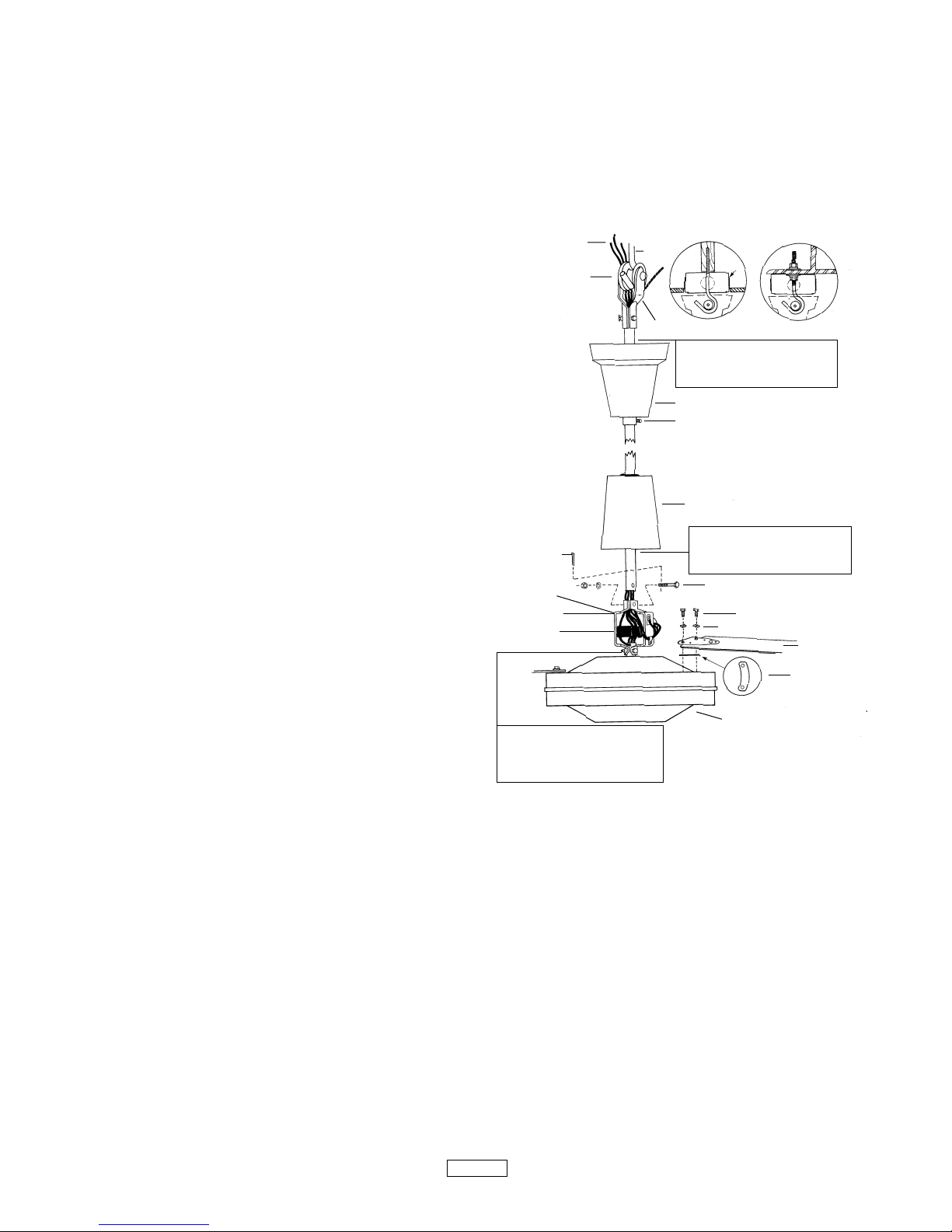
1. Carefully unwrap the coiled safety cable and motor
lead wires.
2. At the motor yoke assembly (A), remove the cotter pin
and loosen the hexagon nut. Carefully remove spring
washer and the hexagon screw (E).
(See Figure 1)
3. Slide the upper canopy cover (B) (bell shaped) up the
rod. Slide the lower canopy cover (C) up to rod.
4. Feed the five wires and the safety cable through the
center hole in the steel yoke connecting piece above
the motor (A) and then continue feeding wires and
cable through the downrod until the wires and cable
come out at the upper (shackle) end.
5. Mount the downrod to the yoke (A) and replace the
hexagon screw. Secure the spring washer hexagon
nut and spread the coffer pin.
NOTICE: The safety cable should be taped to one side
of the yoke with electrical tape to prevent the cable from
resting on top of motor during running operation.
(See Figure 2)
6. Slide the lower canopy (C) to be a 1/4” minimum
height above the motor.
CAUTION: Do not allow the permanently installed
lower canopy to touch the revolving motor as damage will occur. Make sure all wires are securely
placed to avoid rubbing against the motor.
7. Attach the three blades, curved side down to the motor
with the insulation pad mounted between the blade
and the motor. Make sure blade holder is flat against
motor platform when tightening blade nuts for secure
fit.
CAUTION: Blades must be fastened to the motor as
shown in Figure 1. DO NOT reverse blades when
installing.
NOTE: Blades are weight balanced per set. DO NOT mix
on multiple fan installations.
NOTE:Do not bend fan blade brackets.
WARNING: DISCONNECT CIRCUIT POWER BEFORE
MAKING ANY ELECTRICAL CONNECTIONS.
CAUTION: To reduce the risk of personal injury,
install the primary mounting directly from building
structure and use only the hardware provided with
the fan.
8. Before attaching the appropriate “J” hook to the
building structure member note the following:
IMPORTANT. WHEN MOUNTING THIS FAN, THE
SUPPORT BEAM MUST BE SUITABLE FOR A 50
POUND LOAD LIMIT.
Figure 1 - Assembly
WOOD JOIST
METALBEAM
STYLES
HOOK
WIRE
RUBBER
ROLLER
(D) UPPER SHACKLE ASSEMBLY
CAUTION: Leave 1/4” clearance
between upper canopy
and ceiling.
(F) SET SCREW
(B) UPPER CANOPY COVER
DOWNROD
(C) LOWER CANOPY COVER
CAUTION: Leave 1/4” clearance
between lower canopy
and motor housing.
(E) MOUNTING HEX BOLTSET
HEX BOLT
PLASTIC PAD
MOTOR HOUSING
LOCKWASHER
BLADE
CAUTION: Never adjust the
lower shaft bolt assembly which
is precision secured during the
manufacture of this fan.
STEEL YOKE
CAPACITOR
2
COTTER PIN
MOTOR YOKE
ASSEMBLY
 Loading...