

Page 1

MULTI SDI MONITOR
LV 5330
Instruction Manual
LEADER ELECTRONICS CORP.
Page 2

Contents
GENERAL SAFETY SUMMARY ......................................................................................... I
1. Introduction.............................................................................................................. 1-1
1.1 Scope of Warranty ...............................................................................................................1-1
1.2 Handling Precautions...........................................................................................................1-1
1.2.1 Power Supply Voltage...................................................................................................1-1
1.2.2 Maximum Allowable Input Voltage ................................................................................ 1-2
1.2.3 Shorting and Applying External Input to the Output Connectors................................... 1-2
1.2.4 Mechanical Shock.........................................................................................................1-2
1.2.5 Electrostatic Damage.................................................................................................... 1-2
1.2.6 Warming Up.................................................................................................................. 1-2
1.2.7 Trademark Acknowledgments....................................................................................... 1-2
2. Specifications...........................................................................................................2-1
2.1 Product Overview ................................................................................................................2-1
2.2 Features............................................................................................................................... 2-1
2.3 Specifications....................................................................................................................... 2-4
2.3.1 Video Signal Formats and Corresponding Standards................................................... 2-4
2.3.2 Audio Playback............................................................................................................. 2-4
2.3.3 Input/Output Connectors............................................................................................... 2-5
2.3.4 Control Connectors.......................................................................................................2-6
2.3.5 LCD ..............................................................................................................................2-6
2.3.6 Display Modes ..............................................................................................................2-6
2.3.7 Screen Capture.............................................................................................................2-7
2.3.8 Presets .........................................................................................................................2-7
2.3.9 Video Signal Waveform Display....................................................................................2-7
2.3.10 Vector Display...............................................................................................................2-8
2.3.11 5 Bar Display ................................................................................................................ 2-8
2.3.12 Phase Difference Display .............................................................................................2-9
2.3.13 Picture Display.............................................................................................................. 2-9
2.3.14 CINELITE Display.........................................................................................................2-9
2.3.15 CINEZONE Display ....................................................................................................2-10
2.3.16 Audio Display.............................................................................................................. 2-10
2.3.17 Status Display .............................................................................................................2-10
2.3.18 View Finder Display ....................................................................................................2-12
2.3.19 Front Panel .................................................................................................................2-12
2.3.20 Rear Panel.................................................................................................................. 2-12
2.3.21 General Specifications................................................................................................ 2-12
3. Component Names and Functions .......................................................................... 3-1
3.1 Front Panel .......................................................................................................................... 3-1
3.2 Rear Panel...........................................................................................................................3-3
3.3 Top and Bottom Panels........................................................................................................3-4
4. Before You Begin Measuring ................................................................................... 4-1
4.1 Attaching the Ferrite Cores ..................................................................................................4-1
Page 3

4.2 Preparing the Power Supply ................................................................................................ 4-2
4.2.1 Attaching the DC Power Cord....................................................................................... 4-2
4.2.2 Turning On the Power ................................................................................................... 4-2
4.2.3 Turning Off the Power ................................................................................................... 4-2
4.3 Applying SDI Input Signals ..................................................................................................4-3
4.4 Transmitting an SDI Output Signal.......................................................................................4-4
4.5 Applying a Composite Video Signal..................................................................................... 4-4
4.6 Applying an External Sync Signal ........................................................................................4-5
4.7 Using a Tripod......................................................................................................................4-6
4.8 Using a VESA Stand............................................................................................................ 4-6
4.9 General Display Explanation................................................................................................ 4-7
4.10 Basic Menu Operations........................................................................................................4-9
5. System Settings....................................................................................................... 5-1
5.1 Setting the Input Format ......................................................................................................5-1
5.1.1 Setting the Input Format Detection Method .................................................................. 5-1
5.1.2 Selecting i or PsF..........................................................................................................5-2
5.1.3 Setting the Input Format ............................................................................................... 5-2
5.1.4 Setting the Composite Display Format .........................................................................5-3
5.2 Selecting the Monitor’s Color Temperature ..........................................................................5-3
5.3 Display Settings ...................................................................................................................5-3
5.3.1 Displaying the Input Format.......................................................................................... 5-4
5.3.2 Selecting the Date Display Format ...............................................................................5-4
5.3.3 Selecting the Time Display Format............................................................................... 5-4
5.3.4 Displaying the Color System......................................................................................... 5-5
5.3.5 Selecting the Timecode Display Format ....................................................................... 5-5
5.3.6 Setting the Backlight Brightness ...................................................................................5-5
5.3.7 Setting the Backlight Auto Shutoff Time........................................................................5-6
5.3.8 Displaying the Amount of Remaining Battery Power.....................................................5-6
5.4 Configuring the External Interface .......................................................................................5-7
5.4.1 Selecting the Method for Loading Presets ....................................................................5-7
5.4.2 Configuring Ethernet Settings....................................................................................... 5-8
5.5 Setting the Date and Time ...................................................................................................5-9
5.6 Assigning a Function to the SHORT CUT Key..................................................................... 5-9
5.7 Initialization ........................................................................................................................ 5-10
5.7.1 Initializing the Settings Using SETUP INIT ................................................................. 5-10
5.7.2 Initializing the Settings by Restarting the LV 5330 ...................................................... 5-10
6. Presets .................................................................................................................... 6-1
6.1 Registering Presets..............................................................................................................6-1
6.2 Loading Presets...................................................................................................................6-2
6.3 Deleting Presets...................................................................................................................6-3
6.4 Copying Presets...................................................................................................................6-3
6.5 Copying All Presets .............................................................................................................. 6-4
6.5.1 Copying Presets from USB Memory to the LV 5330 .....................................................6-4
6.5.2 Copying Presets from the LV 5330 to USB Memory .....................................................6-4
7. Screen Capture Feature .......................................................................................... 7-1
Page 4

7.1 Taking a Screen Capture of the Display...............................................................................7-2
7.2 Displaying Screen Capture Data on the LV 5330.................................................................7-2
7.3 Saving Screen Capture Data to USB Memory .....................................................................7-3
7.4 Viewing Screen Capture Data from USB Memory ...............................................................7-4
7.5 Deleting Screen Capture Data from USB Memory............................................................... 7-5
8. Picture Display......................................................................................................... 8-1
8.1 Picture Display Explanation .................................................................................................8-1
8.2 Setting the Brightness and Contrast ....................................................................................8-2
8.2.1 Adjusting the Brightness ............................................................................................... 8-2
8.2.2 Adjusting the Contrast ..................................................................................................8-2
8.3 Marker Settings.................................................................................................................... 8-2
8.3.1 Displaying an Aspect Marker ........................................................................................ 8-3
8.3.2 Displaying a Safe Action Marker ...................................................................................8-3
8.3.3 Displaying a Safe Title Marker ......................................................................................8-4
8.3.4 Displaying a Center Marker ..........................................................................................8-4
8.4 Line Selection Settings ........................................................................................................ 8-5
8.4.1 Displaying a Marker on the Selected Line ....................................................................8-5
8.4.2 Selecting a Line ............................................................................................................8-6
8.4.3 Setting the Line Selection Range .................................................................................8-6
8.5 Selecting the Picture Display Size ....................................................................................... 8-6
8.6 Switching between the Color and Monochrome Displays .................................................... 8-7
8.7 Adjusting the Chroma Gain..................................................................................................8-8
8.8 Adjusting the Aperture..........................................................................................................8-8
9. CINELITE Display.................................................................................................... 9-1
9.1 Selecting the Points to Measure .......................................................................................... 9-1
9.2 Moving the Cursors..............................................................................................................9-2
9.3 Selecting the Measurement Area......................................................................................... 9-3
9.4 Displaying Luminance Levels as f Stop Numbers................................................................ 9-3
9.5 Displaying Luminance Levels as Percentages or RGB Values ............................................ 9-5
9.6 Configuring User-Defined Correction Tables........................................................................9-7
9.6.1 Creating User-Defined Correction Tables Using the LV 5330 .......................................9-7
9.6.2 Loading a User-Defined Correction Table into the LV 5330 ........................................9-10
10. CINEZONE Display ............................................................................................... 10-1
10.1 CINEZONE Display............................................................................................................10-1
10.1.1 Selecting the Color Gradation.....................................................................................10-2
10.1.2 Setting the Color Range .............................................................................................10-2
10.2 Level Search Display .........................................................................................................10-3
11. Video Signal Waveform Display............................................................................. 11-1
11.1 Video Signal Waveform Display Explanation ..................................................................... 11- 1
11.2 Display Position Settings ................................................................................................... 11-2
11.2.1 Setting the Vertical Position ........................................................................................ 11- 2
11.2.2 Setting the Horizontal Position.................................................................................... 11-2
11.3 Intensity Settings ............................................................................................................... 11-2
11.3.1 Setting the Video Signal Waveform Intensity.............................................................. 11-2
Page 5

11.3.2 Setting the Scale Intensity .......................................................................................... 11- 3
11.4 Gain and Filter Settings ..................................................................................................... 11- 3
11.4.1 Selecting the Fixed Gain............................................................................................. 11-3
11.4.2 Setting the Variable Gain ............................................................................................ 11- 4
11.4.3 Selecting a Filter ......................................................................................................... 11- 4
11.5 Sweep Settings.................................................................................................................. 11-6
11.5.1 Selecting the Sweep Method ...................................................................................... 11- 6
11.5.2 Selecting the Line Display Sweep Time...................................................................... 11-7
11.5.3 Selecting the Field or Frame Display Sweep Time ..................................................... 11-7
11.5.4 Selecting Which Field to Display................................................................................. 11-8
11.5.5 Selecting the Horizontal Magnification........................................................................ 11-8
11.6 Line Selection Settings .................................................................................................... 11-1 0
11.6.1 Displaying the Waveform of the Selected Line ......................................................... 11-1 0
11.6.2 Selecting a Line ........................................................................................................ 11- 1 0
11.6.3 Setting the Line Selection Range ............................................................................. 11- 11
11.7 Cursor Settings ................................................................................................................ 11-11
11.7.1 Displaying Cursors.................................................................................................... 11-11
11.7.2 Selecting the Cursor Type ........................................................................................ 11-12
11.7.3 Moving the Cursors................................................................................................... 11-12
11.7.4 Setting the Units of Measurement............................................................................. 11-13
11.7.5 Setting the Base Value ............................................................................................. 11-13
11.8 Color System Settings ..................................................................................................... 11-14
11.8.1 Selecting the Display Format.................................................................................... 11-14
11.8.2 Displaying the GBR or RGB Signal Simultaneously with the Luminance Signal....... 11-1 5
11.8.3 Setting the Setup Level............................................................................................. 11-16
11.9 Scale Settings.................................................................................................................. 11-17
11.9.1 Selecting the Scale Unit............................................................................................ 11-17
11.9.2 Displaying a Scale for 75 % Color Bars.................................................................... 11-18
11.9.3 Changing the Scale Color......................................................................................... 11-18
11.10 Displaying the Blanking Interval....................................................................................... 11-19
11.11 Setting the Display Mode to TIMING................................................................................ 11-19
11.12 Switching the Display Mode............................................................................................. 11-20
11.13 Turning Y,CB,CR; GBR; and RGB Channels On and Off.................................................. 11-2 1
12. Vector Display........................................................................................................ 12-1
12.1 Vector Display Explanation ................................................................................................12-1
12.2 Vector and Scale Settings.................................................................................................. 12-2
12.2.1 Setting the Vector Intensity ......................................................................................... 12-2
12.2.2 Setting the Scale Intensity ..........................................................................................12-2
12.2.3 Displaying the I and Q Axes........................................................................................ 12-3
12.2.4 Changing the Scale Color........................................................................................... 12-3
12.3 Gain Settings ..................................................................................................................... 12-4
12.3.1 Selecting the Fixed Gain............................................................................................. 12-4
12.3.2 Setting the Variable Gain............................................................................................ 12-4
12.4 Line Selection Settings ...................................................................................................... 12-5
12.4.1 Displaying the Vectors of the Selected Line................................................................ 12-5
12.4.2 Selecting a Line ..........................................................................................................12-6
12.4.3 Setting the Line Selection Range ............................................................................... 12-6
Page 6

12.5 Color System Settings ....................................................................................................... 12-7
12.5.1 Selecting the Display Format ...................................................................................... 12-7
12.5.2 Setting the Setup Level............................................................................................... 12-8
12.5.3 Displaying a Scale for 75 % Color Bars ......................................................................12-8
12.6 Switching between the Vector, 5 Bar, and Phase Difference Displays............................... 12-9
12.6.1 5 Bar Display Explanation...........................................................................................12-9
12.6.2 Explanation of the Phase Difference Display ............................................................12-10
12.7 Phase Difference Display Settings................................................................................... 12-12
12.7.1 Setting the Phase Difference Memory Number......................................................... 12-13
12.7.2 Recording the Current Phase Difference .................................................................. 12-13
12.7.3 Deleting Recorded Phase Differences...................................................................... 12-13
12.7.4 Setting the Current Phase Difference to Zero ...........................................................12-13
12.7.5 Initializing the Phase Difference Settings..................................................................12-13
13. Audio Display......................................................................................................... 13-1
13.1 Audio Display Explanation .................................................................................................13-1
13.2 Selecting the Display Mode ...............................................................................................13-2
13.3 Selecting Which Channels to Measure ..............................................................................13-3
13.4 Channel Mapping Settings.................................................................................................13-4
13.5 Meter Settings.................................................................................................................... 13-5
13.5.1 Setting the Reference Level ....................................................................................... 13-5
13.5.2 Setting the Range .......................................................................................................13-5
13.5.3 Selecting the Scale ..................................................................................................... 13-6
13.5.4 Setting the Peak Value Hold Time .............................................................................. 13-6
13.5.5 Meter Settings Overview............................................................................................. 13-7
13.6 Headphone Settings .......................................................................................................... 13-8
13.6.1 Turning Headphone Output On and Off...................................................................... 13-8
13.6.2 Adjusting the Headphone Volume...............................................................................13-8
13.6.3 Selecting the Headphone Jack Output Channels .......................................................13-9
14. Status Display ........................................................................................................ 14-1
14.1 Status Display Explanation ................................................................................................ 14-1
14.2 Event Log Settings............................................................................................................. 14-4
14.2.1 Event Log Explanation................................................................................................ 14-4
14.2.2 Scrolling through the Event Log..................................................................................14-6
14.2.3 Starting Event Logging................................................................................................14-6
14.2.4 Deleting the Event Log ...............................................................................................14-6
14.2.5 Setting the Event Log Overwrite Mode .......................................................................14-7
14.2.6 Saving the Event Log to USB Memory .......................................................................14-7
14.2.7 Deleting Event Logs in USB Memory.......................................................................... 14-7
14.3 Data Dump Settings........................................................................................................... 14-8
14.3.1 Data Dump Explanation.............................................................................................. 14-8
14.3.2 Selecting the Data Dump Display Mode .....................................................................14-9
14.3.3 Selecting the Data Dump Display Format................................................................. 14-10
14.3.4 Selecting the Data Dump Display Start Position ....................................................... 14-11
14.3.5 Selecting Data Dump Lines and Samples ................................................................ 14-11
14.3.6 Saving a Data Dump to USB Memory ......................................................................14-12
14.3.7 Deleting Data Dumps in USB Memory...................................................................... 14-12
Page 7

14.4 Audio Status Settings.......................................................................................................14-13
14.4.1 Audio Status Display Explanation .............................................................................14-13
14.4.2 Selecting Which Channels to Display ....................................................................... 14-14
14.5 Ancillary Packet Settings .................................................................................................14-15
14.5.1 Explanation of the Ancillary Packet Display.............................................................. 14-15
14.5.2 EDH Packet Display Explanation.............................................................................. 14-17
14.5.3 Format ID Display Explanation .................................................................................14-19
14.5.4 Subtitle Packet Display Explanation .........................................................................14-21
14.5.5 Inter-Stationary Control Signal Display Explanation..................................................14-23
14.6 Error Settings................................................................................................................... 14-25
14.6.1 Selecting the Alarm Signal Polarity........................................................................... 14-25
14.6.2 Selecting the Error Count Rate .................................................................................14-25
14.6.3 Configuring Error Detection Settings ........................................................................14-26
14.6.4 Setting Gamut Error Detection Levels ......................................................................14-30
14.6.5 Setting Composite Gamut Error Detection Levels ....................................................14-31
14.6.6 Selecting the Error Display Format ...........................................................................14-32
14.7 Resetting Errors............................................................................................................... 14-32
15. View Finder Display............................................................................................... 15-1
15.1 Adjusting the Brightness ....................................................................................................15-1
15.2 Adjusting the Contrast........................................................................................................15-1
15.3 Adjusting the Chroma Gain................................................................................................15-2
15.4 Adjusting the Aperture........................................................................................................15-2
16. Multi-Screen Display Feature ................................................................................16-1
16.1 Selecting the Multi-Screen Display Format........................................................................ 16-1
16.2 Setting Each Measurement Mode...................................................................................... 16-2
16.3 Selecting the Displayed Contents in 4 SCREEN Display Mode......................................... 16-3
17. External Interface ..................................................................................................17-1
17.1 Remote Control Feature ....................................................................................................17-1
17.1.1 Remote Control Connector Specifications .................................................................. 17-1
17.1.2 Loading Presets..........................................................................................................17-2
17.1.3 Transmitting Alarm Signals .........................................................................................17-2
17.1.4 Displaying a Tally Light ...............................................................................................17-2
17.2 TELNET ............................................................................................................................. 17-3
17.2.1 Procedure ...................................................................................................................17-3
17.2.2 How to Enter Commands............................................................................................17-4
17.2.3 TELNET Commands................................................................................................... 17-4
17.3 FTP.................................................................................................................................. 17-10
17.3.1 Procedure .................................................................................................................17-10
17.3.2 How to Enter Commands..........................................................................................17-10
17.3.3 FTP Commands........................................................................................................ 17-11
17.4 SNMP .............................................................................................................................. 17-11
18. Calibration and Repairs ......................................................................................... 18-1
19. APPENDIX ............................................................................................................19-1
Page 8

19.1 Menu Tree..........................................................................................................................19-1
19.1.1 Picture Menu ..............................................................................................................19-1
19.1.2 CINELITE Menu..........................................................................................................19-2
19.1.3 CINEZONE Menu .......................................................................................................19-3
19.1.4 Video Signal Waveform Menu ....................................................................................19-3
19.1.5 Vector Menu ............................................................................................................... 19-6
19.1.6 Multi-Screen Display Menu (Audio Menu) ..................................................................19-7
19.1.7 Status Menu................................................................................................................19-8
19.1.8 View Finder Menu..................................................................................................... 19-11
19.1.9 Screen Capture Menu............................................................................................... 19-11
19.1.10 System Menu............................................................................................................ 19-12
19.1.11 Preset Registration Menu ......................................................................................... 559H19-14
279H19.1.12 Preset Menu ............................................................................................................. 560H19-15
280H19.2 About the Firmware Version.............................................................................................561H19-15
Index
Page 9
GENERAL SAFETY SUMMARY
■ To Avoid Personal Injury
It is recommended that only qualified personnel with technical knowledge use this instrument
only after reading and fully understanding all functions of the instrument described this
instruction manual.
This instrument is not designed and manufactured for consumers.
If you do not have enough knowledge on electricity, to avoid personal injury and prevent
damage to this product, please be sure to use this product only under the supervision of an
engineer who has sufficient knowledge about electronics.
■ Precautions on Contents
Should you find the contents in this manual and any of its technical terms confusing, please
feel free to contact your local LEADER agent.
■ Symbols and Terms
Following terms and symbols indicate necessary warnings and cautions used in this manual
and on the product are there for safe operation.
<Symbol>
<Te rm >
WARNING
<Te rm >
CAUTION
The sections where this symbol is marked in this manual or instrument, if
not correctly performed or practiced, could result in personal injury or
cause serious danger to the instrument.
Misuse could also produce unintentional movement to create an
operational impediment on the instrument or other products that might be
connected to it.
Be sure to refer to the safety precautions in this manual to safely use the
part of the instrument where the symbol is marked.
Warning statements identify warning conditions that if disregarded or not
correctly performed or adhered to, could result in serious personal injury
or even loss of life.
Caution statements identify caution conditions that if disregarded or not
correctly performed or adhered to, could result in personal injury or
damage to the instrument.
I
Page 10

GENERAL SAFETY SUMMARY
Review the following safety precautions to avoid operator’s injury and loss of life and prevent
damage and deterioration to this instrument. To avoid potential hazards, use this product as
specified.
■ Warnings on the Cases and Panels of the Instrument
Operator should not remove any cases or panel for any reasons. If you touch inside the
instrument it could result personal shock or fire hazard. Refrain from spilling any liquid
on or inserting anything flammables or piece of metal into the ventilation of the instrument.
Such actions could cause fire, shock, malfunction and be an accident hazard while the
power is on.
■ Warnings on Power Line
● This instrument works in the DC power supply, and uses an accessory AC adaptor.
There is danger of the product malfunction and a fire when things other than
specification are used.
■ Warning on Installation Environments
● About the Operating Temperature Range
Operate the instrument between the temperature range of 0 to 40 °C. Operating the
instrument at higher temperatures could cause a fire hazard.
Rapid changes of temperatures from cold to warm can create internal moisture or
condensation and could damage the instrument. If there is a possibility of moisture
condensation allow the instrument to sit for 30 minutes without the power on.
● About the Operating Humidity Range
Operating humidity range is < 85 % RH. (without condensation)
Do not operate the instrument with wet hands, this could cause a shock and fire
hazard.
● About the Operation in the Presence of Gasses
Operating the instrument in and near the presence or storage locations of flammable,
explosive gasses or fumes could create an explosion and fire hazard. Do not operate
the instrument anywhere near such environments.
● Avoid Insertions
Do not insert metals or flammable objects or drop liquid on or into the instrument. To
do so could cause fire, shock, malfunction and create a dangerous accident hazard.
WARNING
II
Page 11

GENERAL SAFETY SUMMARY
■ Warning about Ground
The instrument has a ground terminal to avoid electric shock hazard and to protect the
instrument from damage. Ensure that the product is properly grounded for safe
operation.
■ Warning while Operating
While operating the instrument if smoke, fire, or a bad smell occurs, turn off the
instrument at once for it could cause a fire hazard. To turn off the power when such a
case may occur, pull out the plug of an AC/DC adaptor. Contact your local LEADER
agent after confirming there is no fire.
WARNING
III
Page 12

GENERAL SAFETY SUMMARY
■ Caution on Input/Output Terminals
Input Terminals are rated with a maximum input. Do not supply an input over the
specified rating in the standard section of the instruction manual. Also, do not supply
external power to Output terminal, this could cause the instrument to malfunction.
■ Caution when Not Using the Instrument for a Long Time
Make sure to disconnect the power cord of the AC adaptor from the socket when you do
not use the instrument for a long time.
・・・・・・・・・・・・・・・・・・・・・・・・・・・・・・・・・・・・・・・・・・・・・・・・・・
Please conform to the above warnings and cautions for safe operation. There are cautions in
each area of in this instruction manual, so please conform to each caution. If you have any
questions about this manual, please feel free to contact your local LEADER agent.
<Calibration>
This instrument is produced under the strictest quality controls at the factory, but accuracy
may gradually deteriorate due to worn components.
Therefore, periodic calibration should be performed.
When service or calibration is required, contact your local LEADER agent.
<Routine Maintenance>
Remove the power cord plug from the socket when cleaning the instrument.
Avoid the use of thinner or benzene solvents for cleaning cases, panels and knobs since
this might remove the paint or damage plastic surfaces.
Wipe cases, panels, and knobs lightly with a soft cloth damped with neutral detergent.
Do not allow water, detergent, or other foreign objects to enter the instrument while
cleaning.
If a liquid or metal object enters the instrument, it can cause electric shock or fire.
CAUTION
IV
Page 13

1. Introduction
Thank you for purchasing this LEADER instrument. To use this instrument safely, read this
instruction manual thoroughly, and make sure that you know how to use the instrument
properly.
If some point about the operation of this instrument is still unclear after you have read this
instruction manual, refer to the contact information on the back cover of the manual to contact
LEADER, or contact your local LEADER agent.
After you have finished reading this manual, keep it in a convenient place so that you can refer
to it when necessary.
1.1 Scope of Warranty
This LEADER instrument has been manufactured under the strictest quality control
guidelines.
LEADER shall not be obligated to furnish the following free services during the warranty
period.
1 Repair of malfunction or damages resulting from fire, natural calamity, or improper
voltage applied by the user.
2 Repair of an instrument that has been improperly repaired, adjusted, or modified by
personnel other than a factory-trained LEADER representative.
3 Repair of malfunctions or damages resulting from improper use.
4 Repair of malfunctions caused by devices other than this instrument.
5 Repair of malfunctions or damages without the presentation of a proof of purchase or
receipt bill for the instrument.
1.2 Handling Precautions
1. Introduction
1.2.1 Power Supply Voltage
WARNING
The operating supply voltage range of this instrument’s DC power supply is 10 to 18 V. Do
not apply a voltage that exceeds this range. Doing so may damage the instrument or lead
to fire.
1-1
Page 14
1. Introduction
1.2.2 Maximum Allowable Input Voltage
CAUTION
Table 1-1 indicates the maximum signal voltage that can be applied to the input
connectors.
Do not apply excessive voltage to the connectors. Doing so may damage the instrument or
lead to injury.
Table 1-1 Maximum allowable input voltage
Input Connector
INPUT SDI A, INPUT SDI B ±2V (DC + peak AC)
INPUT VIEW FINDER ±2V (DC + peak AC)
EXT REF ±5 V (DC + peak AC)
REMOTE 0 to +5 V
Maximum Allowable
Input Voltage
1.2.3 Shorting and Applying External Input to the Output Connectors
Do not short the output connectors. Doing so may damage the instrument.
Do not apply an external signal to the output connectors. Doing so may damage the
instrument and devices that are connected to it.
1.2.4 Mechanical Shock
This instrument contains sensitive components, such as a crystal oscillator, so it may be
damaged if it is dropped or otherwise exposed to a strong shock.
1.2.5 Electrostatic Damage
Electronic components can be damaged by static discharge. Static electricity can build up
in the core wire of a coaxial cable. Before connecting a coaxial cable to the instrument,
short the core wire of the cable with an external conductor.
1.2.6 Warming Up
To achieve more accurate measurements, turn on the instrument approximately 30 minutes
before you intend to use it to allow its internal temperature to stabilize.
1.2.7 Trademark Acknowledgments
Windows is a registered trademark of Microsoft Corporation in the United States and other
countries.
1-2
Page 15

2. Specifications
2.1 Product Overview
The LV 5330 is a multi SDI monitor with support for HD-SDI and SD-SDI.
In creating the LV 5330, we prioritized on-site use. This has led to a compact, light,
energy-saving design.
With its wide range of features, including picture display, video signal waveform display,
vector display, audio level display, error detection, and data analyses, the LV 5330 can be
used for both high-precision measurement and monitoring.
The LV 5330 also comes standard-equipped with CINELITE II, a powerful tool for analyzing
video signal luminance data, and an analog input connector that enables the LV 5330 to be
used as a camera viewfinder.
2.2 Features
• SDI I/O
The LV 5330 has two SDI input connectors that can be used for both HD-SDI and
SD-SDI input. It also has an SDI output connector that you can use to send a reclocked
SDI signal.
• View Finder Input Connector
2. Specifications
The LV 5330 can receive and display analog composite signals (NTSC and PAL). It
comes with a peaking feature that assists in focus adjustment.
• TFT LCD
The LV 5330 has an XGA (1,024 × 768) 6.5-inch color TFT LCD.
The LCD can display video signal waveforms, vectors, pictures, audio levels, and status
information.
You can also view combinations of these items using the LV 5330 multi-screen display
feature.
• Picture Display
The LV 5330 uses fully digital waveform display processing to achieve high precision and
versatility. The display has a number of adjustment features such as color temperature
selection, brightness adjustment, contrast adjustment, aperture adjustment, and chroma
gain adjustment. It also has monochrome and safety marker display features.
• CINELITE II
The LV 5330 comes standard-equipped with CINELITE II (CINELITE and CINEZONE),
which is a video signal luminance information analysis tool.
With CINELITE, you can use the cursor to select any 3 points and display their f-Stop
numbers, percentage values, and level values. You can choose to analyze a single pixel
or a small area by setting the size of the measured area to 1 pixel or to the average value
for 9 or 81 pixels.
With CINEZONE, you can display the luminance levels in the picture using different
colors. This allows you to quickly determine the overall luminance distribution in the
picture, and it makes it easy to spot overexposure, underexposure, and different
luminance levels in dark areas.
2-1
Page 16

2. Specifications
• Video Signal Waveform Display
The LV 5330 uses fully digital waveform display processing to achieve high precision and
quality. From video signal waveform display gain expansion, sweep expansion, and
cursor measurement to pseudo-composite and RGB displays, the LV 5330 has all of the
features that people look for in a waveform monitor. The LV 5330 is equipped with an
external sync signal input and it can display video signal waveforms based on a tri-level
sync signal or an NTSC or PAL black burst signal.
• Vector Display
The LV 5330 can display component chrominance signal vectors.
The amplitude can be manually zoomed, or set to a fixed magnification value such as
five.
The IQ axes, which are useful for vector observation, can be turned on and off.
• 5 Bar Display
The LV 5330 can display the peak levels of the Y, R, G, B and pseudo-composite signals.
This feature is useful for monitoring gamut errors.
• Audio Level Display
The LV 5330 can extract the audio signal embedded in an SDI signal and display levels
and values for up to eight channels. (The maximum SD-SDI audio quantization level is
20 bits.)
• Stereo Headphone Output
The LV 5330 can extract the audio signal embedded in an SDI signal. You can select two
channels from the extracted audio and transmit them in stereo through the headphone
output connector.
• Status Display
The status display has a number of advanced features, including SDI signal error
detection and analysis features.
• Error Detection
The error detection feature can help you to catch transmission errors such as CRC
errors (HD-SDI), EDH errors (SD-SDI), BCH errors, and checksum errors.
• Event Log
The ability to log events such as detected errors and input signal switching makes
long-term error monitoring easy. The event log can be saved to USB memory or sent
to a PC through an Ethernet connection as text data.
• Data Dump
The ability to display digital data after parallel conversion in hexadecimal or binary
format is useful when there is a problem and is also useful for various kinds of data
analysis. Data dumps can be saved to USB memory or sent to a PC over an Ethernet
as text data.
• Packet Analysis
The LV 5330 can analyze and display the various packets embedded in an SDI signal.
2-2
Page 17

2. Specifications
• Time Code Display
The LV 5330 can decode SMPTE RP-188 time codes (LTC or VITC) and display them.
These codes can be used as timestamps in the event log.
• Screen Capture
The display can be captured. Captured displays can be viewed or superimposed over an
input signal.
Captured displays can be saved in internal memory (RAM) or USB memory or sent to a
PC through an Ethernet connection as bitmap data.
• Presets
The LV 5330 can remember up to 30 frequently used setting configurations. The
configurations can be recalled easily from the front panel or using commands sent
through the Ethernet or remote connector.
• Remote Connector
You can recall presets by sending commands through the remote connector.
Also, a tally light can be displayed on the screen.
• Ethernet Connector
From a PC connected to the LV 5330 through the Ethernet connector, you can recall
presets, execute panel operations, transfer files, and monitor errors.
• Last Memory
The LV 5330 backs up the current settings so that you can use the same settings that
you were using before immediately after powering it up.
• 75-mm VESA Mounting
The LV 5330 has 75-mm VESA mounting holes on its rear panel that allow it to be
mounted on an arm or stand.
• Tripod Attachment
The tripod adapter on the bottom of the LV 5330 can also be removed and placed on the
top.
• Power Supply
The LV 5330 has an XLR DC input connector and runs on a 12-VDC power supply.
As a factory option, a battery adapter can be attached to the rear of the LV 5330. With
this option, the LV 5330 can use the kinds of batteries that are used in video cameras
and other equipment.
(The 75-mm VESA mounting holes cannot be used if the LV 5330 has a battery adapter
attached to it.)
* Ethernet features (SNMP) and the battery option will be supported in the future.
2-3
Page 18
2. Specifications
2.3 Specifications
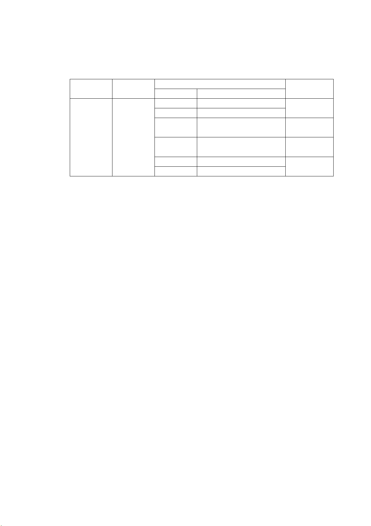
2.3.1 Video Signal Formats and Corresponding Standards
Table 2-1 Video signal formats and corresponding standards
Color System Quantization
Y, C B,CR 4:2:2 10 bits
Format Setting Can be set automatically based on the
Supported Sampling Frequencies
HD 74.25 MHz or 74.25/1.001 MHz
SD 13.5 MHz
External Sync Automatically set from the corresponding
2.3.2 Audio Playback
Format
Scanning Frame (Field) Rates
1080i 60/59.94/50
1080p 30/29.97/25/24/23.98
1080PsF 30/29.97/25/24/23.98
720p
525i 59.94
625i 50
60/59.94/50
30/29.97/25/24/23.98
corresponding format or set manually
format
Compliant
Standard
SMPTE 274M
SMPTE 292M
SMPTE RP 211
SMPTE 292M
SMPTE 296M
SMPTE 292M
SMPTE 259M
Compliant Standard
HD SMPTE-299M
SD SMPTE-272M
Sampling Frequency 48 kHz (must be synchronized to the video
signal)
Quantization
HD 24 bits
SD 20 bits
Clock Generation Video clock
Synchronization All audio channels must be synchronized to the
video clock.
Phases All phases must be in-sync.
Channel Separation Two groups of eight channels are selectable.
2-4
Page 19

2.3.3 Input/Output Connectors
SDI Input
Input Connector 2 BNC connectors (A/B switching)
Input Impedance 75 Ω
Input Return Loss ≥ 15 dB for 5 MHz to the serial clock frequency
Maximum Input Voltage ±2V (DC + peak AC)
SDI Output
Output Connector 1 BNC connector
Output Impedance 75 Ω
Output Voltage 800 mVp-p ± 10 %
View Finder Input
Function Used to display the picture of a composite
Input Connector 1 BNC connector
Input Impedance 75 Ω
Input Signal NTSC or PAL VBS
Input Voltage 1 Vp-p
Maximum Input Voltage ±2V (DC + peak AC)
*
External Reference Input
Input Signal Tri-level sync or NTSC/PAL black burst signal
Input Connector 1 pair of BNC connectors
Input Impedance 15 kΩ passive loop-through
Input Return Loss ≥ 30 dB for 50 kHz to 30 MHz
Maximum Input Voltage ±5 V (DC + peak AC)
Headphone Output
Output Signal The LV 5330 extracts and transmits the audio
Output Connector 1 stereo miniature jack
Volume Adjustment Configured in the menu
Impedance 32 Ω (16 to 600 Ω)
* If the video signal waveform or phase difference is displayed using an external sync signal as
reference, the waveform phase one clock before or after an SDI signal is inserted or the power is
turned on is indefinite.
2. Specifications
Reclocks and transmits the selected SDI input
signal
video signal
signal embedded in an SDI signal.
(Must be synchronized to the video signal.)
2-5
Page 20

2.3.4 Control Connectors
USB Port
Function Used to save screen captures, event logs,
Compliant Standard USB 2.0
Media Only USB memory devices are supported.
Remote Connector
Function Used to recall presets, display a tally light, and
Control Signal TTL level (active-low logic)
Control Connector 15-pin D-sub (female)
Ethernet (SNMP to be supported in the future)
Function Used to control the LV 5330 from a PC and
Compliant Standard IEEE802.3
Input/Output Connectors 1 RJ-45 connector
Type 10Base-T/100Base-TX (automatic switching)
2.3.5 LCD
2. Specifications
preset data, and data dumps
switch input channels (A/B)
monitor errors and other events
LCD Type 6.5-inch color TFT
Format XGA. The effective resolution is 1,024 × 768.
Backlight Brightness Can be set to HIGH or LOW
Auto Shutoff LCD can be automatically turned off after a set
2.3.6 Display Modes
Single Screen Picture display, CINELITE display, CINEZONE
2 Screen Picture display and video signal waveform
Video signal waveform display and picture
Video signal waveform display and audio level
Audio level values and meters
4 Screen Display Vector display, video signal waveform display,
Format Display Displays the video signal format at the top of
Color System Display Displays the video signal color system at the
Date Display Displays the date according to the internal clock
Time or Time Code Display Displays the time according to the internal clock
Time Code LTC or VITC
Compliant Standard SMPTE RP-188
period of time.
display, video signal waveform display, vector
display, status display, or view finder display
display
Video signal waveform display and vector
display
display
display
status display, and picture display (the status
display can be switched to the audio level
display)
the screen.
top of the screen.
at the top of the screen
or a time code at the top of the screen
2-6
Page 21

2.3.7 Screen Capture
Function Captures the screen
Display Displays the captured image or superimposes
Media Internal memory (RAM) and USB memory
Data Output Screen captures can be saved as bitmap files
Data Input Data saved to USB memory can be loaded and
2.3.8 Presets
Number of Presets 30
Recall Method Front panel or remote connector or Ethernet
Copying Preset configurations can be copied as a group
2.3.9 Video Signal Waveform Display
2. Specifications
the captured image over the input signal
Only one screen capture can be stored in the
internal memory.
or in a file format that the LV 5330 can load.
They can be saved to USB memory or
transmitted through an Ethernet and saved on a
PC.
displayed on the LV 5330.
command
to or from USB memory.
Waveform Operations
Display Modes
Overlay Overlays component signals.
Parade Displays component signals side by side.
Timing Computes and displays Y-C
B and Y-CR.
Uses a bowtie signal (permission to use
patented technology granted by Tektronix, Inc.).
Blanking Period Show or hide
RGB Conversion Converts a Y,C
B,CR signal into an RGB signal
and displays the result.
Pseudo-Composite Display Artificially converts component signals into
composite signals and displays the result.
Channel Assignment In RGB conversion display, the order can be set
to GBR order or RGB order.
Line Select Displays the selected line.
Sweep Modes H and V
Vertical Axis
Gain ×1 or ×5
Variable Gain ×0.2 to ×2.0
Amplitude Accuracy ±0.5 %
HD Frequency Characteristics
Y Signal ±0.5 % for 1 to 30 MHz
C
B,CR Signals ±0.5 % for 0.5 to 15 MHz
Low-Pass Attenuation ≥ 20 dB (at 20 MHz)
2-7
Page 22

SD Frequency Characteristics
Y Signal ±0.5 % for 1 to 5.75 MHz
CB,CR Signals ±0.5 % for 0.5 to 2.75 MHz
Low-Pass Attenuation ≥ 20 dB (at 3.8 MHz)
Horizontal Axis
Line Display ×1, ×10, ×20, ACTIVE, or BLANK
Field Display ×1, ×20, or ×40
Cursor Measurement
Composition
Horizontal Cursors 2 (REF and DELTA)
Vertical Cursors 2 (REF and DELTA)
Amplitude Measurement %, mV, or R%
Time Measurement sec
Frequency Display Computes and displays the frequency with the
Scale
Type %, V, 3FF, 1023, FF, or 255
75 % Marker Displays the locations of the peaks of the
Display Colors 7 colors to choose from
2.3.10 Vector Display
2. Specifications
length of one period set to the time between
two cursors.
chroma of a 75 % color bar test signal.
Gain ×1, ×5, or IQ-MAG
Variable Gain ×0.2 to ×2.0
Amplitude Accuracy ±0.5 %
Blanking Period Masked
Scale
Type 75 % or 100 % (color bar)
IQ Axis Show or hide
Display Colors 7 colors to choose from
Line Select Displays the selected line
Pseudo-Composite Display Artificially converts component signals into
* In the multi-screen display, the blanking period depends on the video signal waveform display
blanking display settings.
2.3.11 5 Bar Display
Function Displays five peak levels: those
Scale Percentage
Error Level Based on gamut error level and composite
Filter Removes transient errors
Line Select Displays the selected line
*
composite signals and displays the result.
of the Y, R, G, B and composite signals.
gamut error level settings.
(HD: 5 MHz LPF. SD: 1.8 MHz LPF)
2-8
Page 23

2.3.12 Phase Difference Display
Display Displays the phase difference between an SDI
Display Range
Vertical Approx. ±1/2 frame
Horizontal ±1 line
2.3.13 Picture Display
Color Temperature 3200 K, 6500 K, or 9300 K
Image Quality Adjustment Brightness, contrast, chroma level, and
Display Sizes FIT, ×1, or ×2
Color Selection Color or monochrome
Frame Rate The frame rate is converted and displayed
Marker Displays
Center Marker
Aspect Markers
HD 4:3, 14:9, 13:9, 2.35:1, 1.85:1, and 1.66:1
SD 16:9, 14:9, 13:9, 2.35:1, 1.85:1, and 1.66:1
Safe Action Markers 95 %, 93 %, and 90 %
Safe Title Markers 88 % and 80 %
Line Select Marks the selected line
2.3.14 CINELITE Display
2. Specifications
signal and the external sync signal both
numerically and graphically.
aperture
using the internal sync signal.
Function f-Stop display, percentage display, and level
display
f-Stop Display Displays the f value relative to the reference
point
The reference point is set to the value of an
object with a reflection level of 18 %.
f-Stop Gamma Correction
Reference Gamma 0.45 (ITU-R BT709)
User-Defined Correction Tables 3
External Correction Tables 5 (read from USB memory)
Percentage Display Displays luminance or RGB components as
percentages.
Level Display Displays RGB components with 256 levels (8
bits).
Measured points 3
Measurement sizes 1 pixel, 3 × 3 pixels, or 9 × 9 pixels
2-9
Page 24

2.3.15 CINEZONE Display
CINEZONE Display
Function Displays the luminance levels in the picture
Display Colors Linear (1024 colors) or step (12 colors)
Upper Limit Setting -6.3 to 109.4 % (values above the upper limit
Lower Limit Setting -7.3 to 108.4 % (values below the lower limit
Level Search Display
Function Displays a specified luminance level ±0.5 %
Luminance Level Setting -7.3 to 109.4 %
2.3.16 Audio Display
Level Meter Display
Displayed Channels 8
Meter 60 dB peak level, 90 dB peak level, or average
Peak Hold Time 0.5 to 5.0 seconds/HOLD (when displaying the
Channels
Group Selection: You can select any two groups from groups 1, 2,
Audio Information Detection Detects the presence of each audio channel
Sampling Frequency 48 kHz (must be synchronized to the video
2.3.17 Status Display
2. Specifications
using different colors
are displayed using white)
are displayed using black)
using green on an otherwise monochrome
picture display.
peak level)
3, and 4.
signal)
SDI Signal Error Detection
Signal Detection Detects the presence of an SDI signal
TRS Error Detects TRS location and protection bit errors
Line Number Error Detects HD-SDI signal line number errors
CRC Error Detects HD-SDI signal transmission errors
EDH Error Detects SD-SDI signal transmission errors
Gamut Error Detects gamut errors
Detection Range Upper Limit 90.8 to 109.4 %
Detection Range Lower Limit -7.2 to 6.1 %
Filter Removes transient errors
(HD: 5 MHz LPF. SD: 1.8 MHz LPF)
Composite Gamut Error Detects level errors that occur when component
signals are converted to composite signals
Detection Range Upper Limit 90.0 to 135.0 %
Detection Range Lower Limit -40.0 to -20.0 %
Filter Removes transient errors
(HD: 5 MHz LPF. SD: 1.8 MHz LPF)
Parity Error Detects ancillary data header parity errors
Checksum Error Detects ancillary data transmission errors
2-10
Page 25

2. Specifications
BCH Error Detects errors in the transmission of the audio
signal embedded in an HD-SDI signal
Audio CRC Error Detects CRC errors in channel status bits
Audio Information Detection Detects the presence of each audio channel
Error Count Up to 100,000 errors
(Only the specified errors are counted.)
Count Period Only one error is counted for each second or
frame.
Elapsed Time Time elapsed since the error count was cleared
Event Log Display
Recording Capacity Up to 1,000 events
Description Records all events from start to finish
Recorded Events Errors, changes in input type, time stamps, etc.
Data Output Event logs can be saved to USB memory or
sent to a PC through an Ethernet connection as
text data.
Data Dump Display
Display Modes Display data separated by serial data sequence
or by channel
Line Select Displays the selected line
Sample Select Displays from the selected sample
Jump Feature Jumps to an EAV or SAV
Data Output Event logs can be saved to USB memory or
sent to a PC through an Ethernet connection as
text data.
Audio Status Display
Control Packets Analyzes and displays SDI signal audio control
packets
Channel Status Analyzes and displays or displays the dump of
the channel status of the embedded audio
signal
EDH Display
Compliant Standard SMPTE RP165
Display Details Analyzes and displays received EDH packets
Format ID Display
Compliant Standards SMPTE 352M and ARIB STD-B39
Display Details Analyzes and displays the format ID
Closed Caption Display
Compliant Standard ARIB STD-B37
Display Details Analyzes and displays the closed caption
signal.
Display Formats Text, hexadecimal, and binary
2-11
Page 26

Inter-Stationary Control Data Display (NET-Q)
Compliant Standard ARIB STD-B39
Display Details Analyzes and displays inter-stationary control
Display Formats Text, hexadecimal, and binary
2.3.18 View Finder Display
Display Contents Picture display
Display Size Full screen
Image Quality Adjustment Brightness, contrast, chroma level, and
2.3.19 Front Panel
Key LEDs You can dimly light all of the keys by pressing
Power Switch Turns the power on and off. If power is removed
Last Memory Backs up the panel settings.
2.3.20 Rear Panel
2. Specifications
data
aperture
the shortcut key.
when the switch is on, the instrument will turn
on when power is restored.
Stand Attachment 75-mm VESA Mounting
*
Battery Adapter
As an option, an adapter can be attached that
* (The 75-mm VESA mounting holes cannot be used if the LV 5330 has a battery adapter attached to
it.)
2.3.21 General Specifications
Environmental Conditions
Operating Temperature Range 0 to 40°C
Operating Humidity Range 85 %RH or less (no condensation)
Optimal Temperature Range 10 to 30°C
Optimal Humidity Range 85 %RH or less (no condensation)
Power Supply
Voltage 10 to 18 VDC
Power Consumption 18 W max.
Dimensions 215 × 128 × 63 mm (W × H × D; excluding
Weight 1.4 kg
Accessories Instruction manual......................................... 1
enables the LV 5330 to use batteries produced
by IDX or Anton/Bauer (to be supported in the
future).
protruding parts)
15-pin D-sub connector................................. 1
15-pin D-sub connector cover ....................... 1
VESA spacer................................................. 1
Ferrite core.................................................... 2
2-12
Page 27
3. Component Names and Functions
3. Component Names and Functions
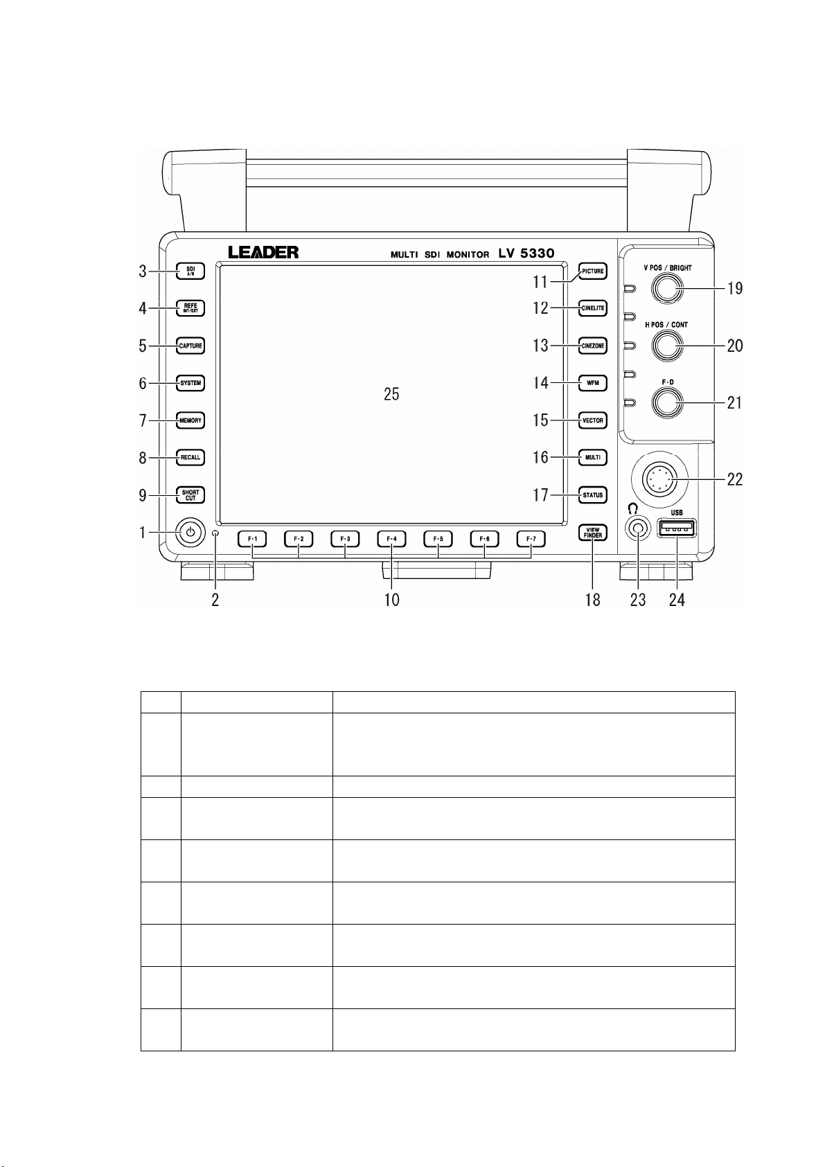
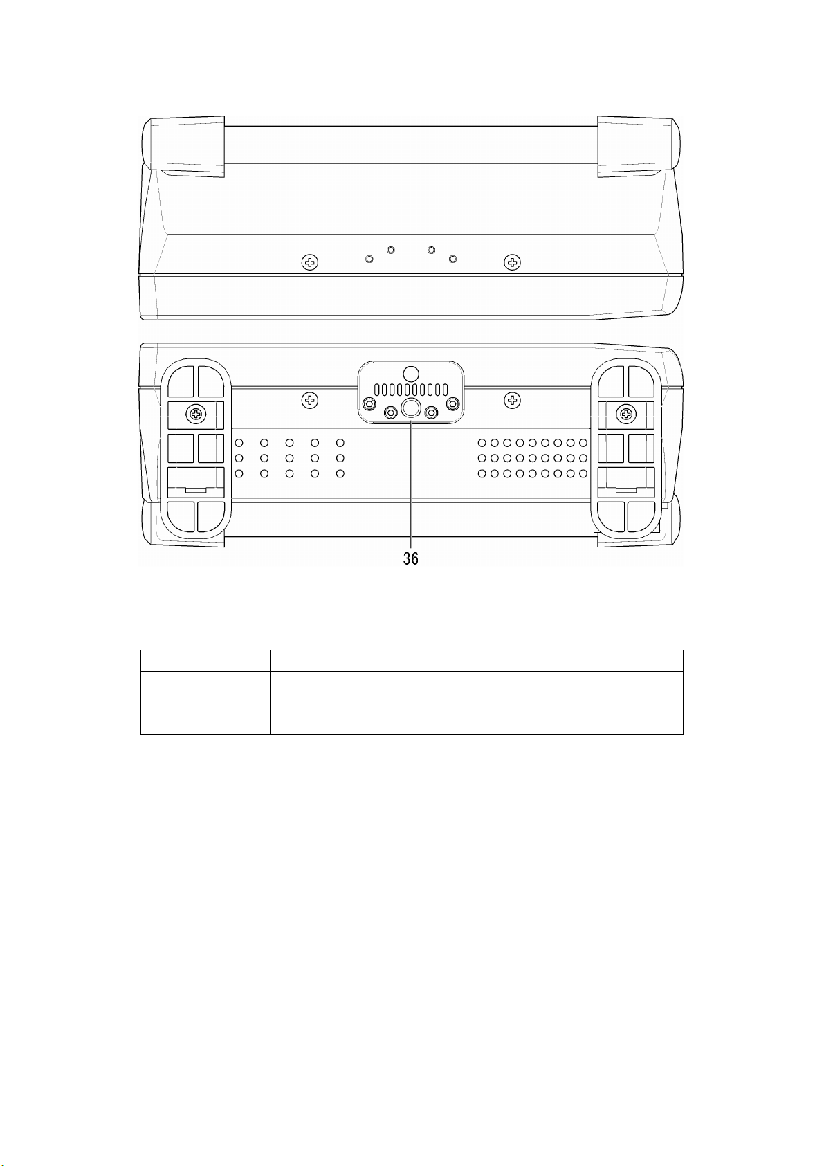
3.1 Front Panel
Figure 3-1 Front panel
Table 3-1 Front panel items and functions
No. Name Function
1 Power switch A quick push switches the power from off to on.
Holding the switch switches the power from on to off.
Reference: Section
2 Power LED Lights when the power is on and turns off when the power is off.
3 SDI A/B key Switches the input channel.
Reference: Section
4 REFE INT/EXT key Switches between the internal sync signal and an external sync signal.
Reference: Section
5 CAPTURE key Takes a screen capture of the display.
Reference: Chapter
6 SYSTEM key Press this key to make system settings.
Reference: Chapter
7 MEMORY key Press this key to save or delete presets.
Reference: Chapter
8 RECALL key Press this key to recall a preset setting configuration.
Reference: Section
4.2, “Preparing the Power Supply”
4.3, “Applying SDI Input Signals”
4.6, “Applying an External Sync Signal”
7, “Screen Capture Feature”
5, “System Settings”
6, “Presets”
6.2, “Loading Presets”
3-1
Page 28
3. Component Names and Functions
No. Name Function
9 SHORTCUT key
10 F・1 to F・7 keys Used to select menu items and pop-up commands.
11 PICTURE key
12 CINELITE key
13 CINEZONE key
14 WFM key
15 VECTOR key
16 MULTI key
17 STATUS key
18 VIEW FINDER key Displays the picture of the composite video signal.
19 V POS/BRIGHT knob Changes the vertical position in the video signal waveform display and
20 H POS/CONT knob Changes the horizontal position in the video signal waveform display
21 F•D knob Mostly used to set values.
22 Control stick Moves the picture in the picture display and moves the cursor in the
23 Headphone jack Use to connect headphones.
24 USB port Use to connect USB memory. USB memory is used to load and save
25 LCD All of the different measurement and data displays appear here.
Can be configured to be used for one of the following operations:
turning on the key LEDs, taking a screen capture, recalling a preset
setting configuration, or adjusting the volume.
Reference: Section
Displays the picture.
Reference: Chapter
Switches to the CINELITE display.
Reference: Chapter
Switches to the CINEZONE display.
Reference: Chapter
Switches to the video signal waveform display.
Reference: Chapter
Switches to the vector display.
Reference: Chapter
Shows multiple displays at the same time.
Switches to the audio display.
Reference: Chapter
Display Feature”
Switches to the status display.
Reference: Chapter
Reference: Chapter
changes the brightness in the picture display. Pushing the knob
returns the value that you are adjusting to its default setting.
Reference: Section
8.2.1, “Adjusting the Brightness”
and changes the contrast in the picture display. Pushing the knob
returns the value that you are adjusting to its default setting.
Reference: Section
“Setting the Horizontal Position”
Generally, pressing this knob will return the value you are adjusting to
its default setting.
Reference: Section
CINELITE display.
Reference: Section
Reference: Section
various kinds of data.
5.6, “Assigning a Function to the SHORT CUT Key”
8, “Picture Display”
9, “CINELITE Display”
10, “CINEZONE Display”
11, “Video Signal Waveform Display”
12, “Vector Display”
13 “Audio Display,” chapter 16, “Multi-Screen
14, “Status Display”
15, “View Finder Display”
11.2.1, “Setting the Vertical Position,” section
8.2.2, “Adjusting the Contrast,” section 11.2.2
4.10, “Basic Menu Operations”
4.10, “Basic Menu Operations”
13.6, “Headphone Settings”
3-2
Page 29
3.2 Rear Panel
3. Component Names and Functions
Figure 3-2 Rear panel
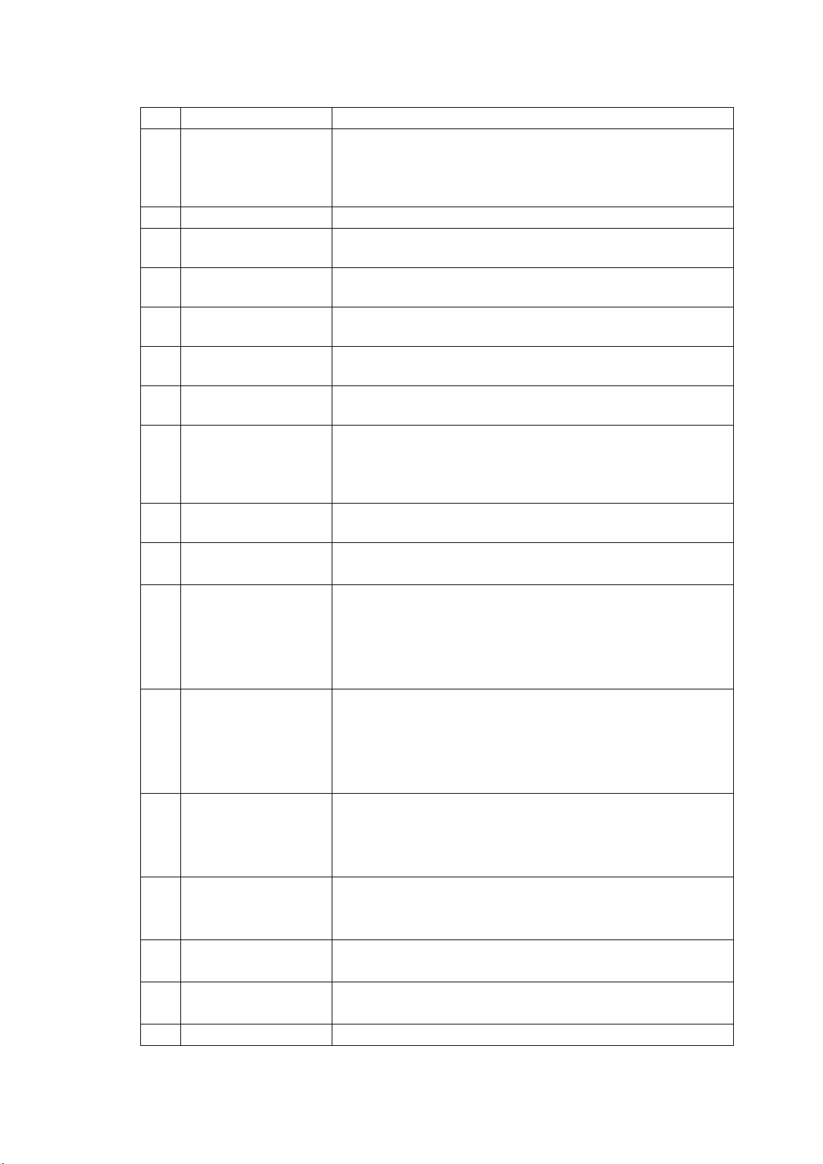
Table 3-2 Rear panel items and functions
No. Name Function
26 EXT REF
27 INPUT VIEW FINDER
28 INPUT SDI A
INPUT SDI B
29 OUTPUT SDI
30 Serial Number Label The serial number is printed here.
31 REMOTE
32 DC INPUT
33 ETHERNET
34 FAN Cooling fan.
35 VESA Mounting Holes VESA compliant (75 × 75 mm) mounting holes.
External reference input connectors. They are loop-through.
Reference: Section
Composite video signal input connector.
Reference: Section
SDI signal input connectors.
Reference: Section
Reclocked SDI signal output connector.
Reference: Section
Remote control connector. Can be used to execute actions such as
recalling presets.
Reference: Section
Input connector for the DC power supply.
Reference: Section
Ethernet connector. Supports TELNET, FTP, and SNMP (to be
supported in the future). Can be used to execute panel operations.
Reference: Section
“SNMP”
Reference: Section
4.6, “Applying an External Sync Signal”
4.5, “Applying a Composite Video Signal”
4.3, “Applying SDI Input Signals”
4.4, “Transmitting an SDI Output Signal”
17.1, “Remote Control Feature”
4.2.1, “Attaching the DC Power Cord”
17.2, “TELNET,” section 17.3, “FTP,” section 17.4,
4.8, “Using a VESA Stand”
3-3
Page 30
3.3 Top and Bottom Panels
3. Component Names and Functions
Figure 3-3 Top and bottom panels
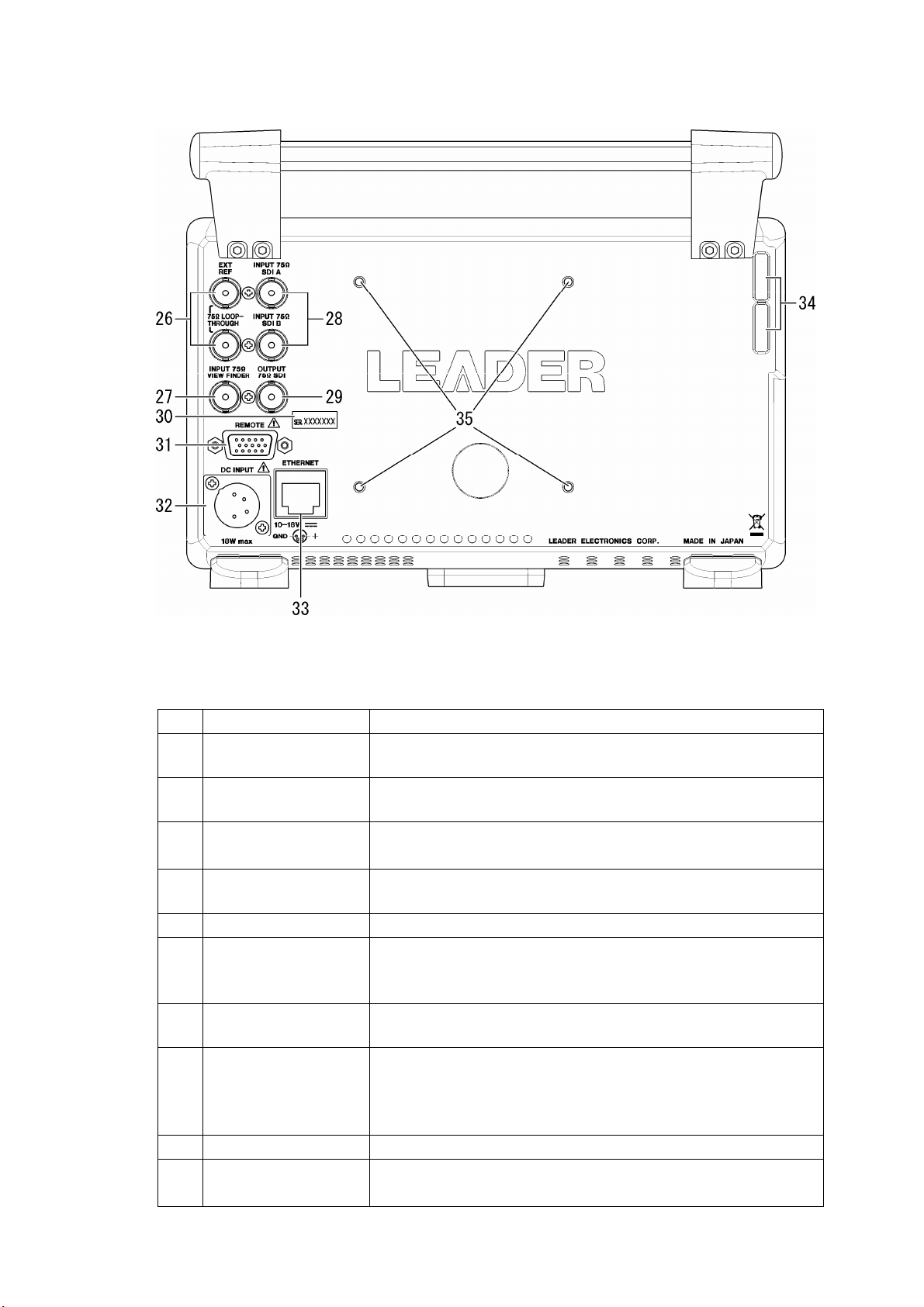
Table 3-3 Top and bottom panel items and functions
No. Name Function
36 Tripod
adapter
Used to attach a tripod to the LV 5330. The tripod adapter can also be
attached to the top panel.
Reference: Section
4.7, “Using a Tripod”
3-4
Page 31

4. Before You Begin Measuring
4. Before You Begin Measuring
4.1 Attaching the Ferrite Cores
Before you connect the LV 5330 to a DC power supply or headphones, attach the ferrite
cores that come with the LV 5330. The ferrite cores reduce the noise that is produced when
you connect cables to the LV 5330.
The steps for connecting a ferrite core to a power cable are listed below. You can follow these
same steps when attaching a ferrite core to a headphone cord.
1. Release the two tabs, and open the ferrite core cover.
Figure 4-1 Ferrite core attachment step 1
2. Attach the ferrite core approximately 5 mm away from the power supply connector (or
headphone jack).
Figure 4-2 Ferrite core attachment step 2
3. Wrap the cable around the core once.
Figure 4-3 Ferrite core attachment step 3
4. Close the ferrite core cover.
Be careful not to pinch the power cord when you close the cover.
Figure 4-4 Ferrite core attachment step 4
4-1
Page 32

4. Before You Begin Measuring
4.2 Preparing the Power Supply
4.2.1 Attaching the DC Power Cord
The DC power supply input connector and its pin assignments are shown below. Apply +12
V to pin 4 shown in the figure below.
When the LV 5330 is connected to the DC power supply, the internal microcomputer is in
standby mode and some power is consumed even if the power switch is turned off. If you
do not intend to use the LV 5330 for an extended period of time, disconnect the DC power
supply.
Figure 4-5 DC power supply input connector
Table 4-1 DC power supply input connector pin alignment
Pin No. Pin Name
1 GND
2 NC*
3 NC*
4 +12 V
* Do not connect anything to this pin.
WARNING
The operating supply voltage range of this instrument’s DC power supply is 10 to 18 V. Do
not apply a voltage that exceeds this range. Doing so may damage the instrument or lead
to fire.
4.2.2 Turning On the Power
To turn on the power, press the power switch on the front panel. The LED next to the power
switch lights when the power is on.
When you turn on the power, the LV 5330 starts up with the same panel settings that were
set when it was last turned off. However, the error counter and event log in the status
display are cleared.
4.2.3 Turning Off the Power
To turn off the power, hold the power switch on the front panel for one second or more. The
LED next to the power switch turns off when you turn off the power.
4-2
Page 33

4. Before You Begin Measuring
4.3 Applying SDI Input Signals
The figure below shows the SDI signal input connectors.
Figure 4-6 SDI input connectors
• The SDI input connectors (INPUT SDI A and INPUT SDI B) are for component SDI (serial
digital interface) signals only. Do not apply analog video signals, composite SDI signals, or
any other kind of signal besides component SDI.
• The SDI input connectors (INPUT SDI A and INPUT SDI B) are terminated internally at 75 Ω.
You do not need to attach a terminator. Connect each of the SDI input connectors to a cable
with a characteristic impedance of 75 Ω.
• Make sure that the SDI input signal strength is 800 mVp-p ± 10 % at the input signal source
BNC output connector. An SDI signal that is outside of this range may not be received
properly.
• You can press SDI on the front panel to switch from measuring the signal being applied to
one connector to measuring the signal being applied to the other connector.
• The LV 5330 supports the formats listed in the table below. The input format is detected
automatically by default. To set the input format manually, see section
Format.”
Table 4-2 Supported formats
5.1, “Setting the Input
Scanning Frame or Field Rates
1080i 60, 59.94, 50
1080PsF 30, 29.97, 25, 24, 23.98
1080p 30, 29.97, 25, 24, 23.98
720p 60, 59.94, 50, 30, 29.97, 25, 24, 23.98
525i 59.94
625i 50
CAUTION
The maximum allowable voltage of the SDI input connectors is ±2 V. Do not apply excessive
voltage to the connectors. Doing so may damage the instrument or lead to injury.
4-3
Page 34

4. Before You Begin Measuring
4.4 Transmitting an SDI Output Signal
The signal that the SDI output connector delivers is a reclocked version of the SDI signal that
has been selected using the SDI on the front panel. Use the output connector to transmit the
signal to a picture monitor that supports SDI signals.
The output impedance of the connector is 75 Ω. Terminate the other end at 75 Ω.
Figure 4-7 SDI output connector
4.5 Applying a Composite Video Signal
The figure below shows the composite video signal input connector. You can only check the
picture of a signal that is applied to the connector. You can check the picture by viewing the
signal in a view finder display.
The composite video input connector is terminated internally at 75 Ω, so there is no need to
connect a terminator to it when it is not in use. Connect the composite input connector to a
cable with a characteristic impedance of 75 Ω.
Figure 4-8 Composite video input connector
CAUTION
The maximum allowable voltage of the external reference input connectors is ±2 V. Do not
apply excessive voltage to the connectors. Doing so may damage the instrument or lead to
injury.
4-4
Page 35

4. Before You Begin Measuring
4.6 Applying an External Sync Signal
You can use an external sync signal for in the video signal waveform and vector displays.
Apply a tri-level sync signal or an NTSC/PAL black burst signal to the external reference input
connectors. The LV 5330 determines the sync signal format automatically.
Figure 4-9 External reference input connectors
• As shown in the figure below, the external reference input connectors are loop-through. Apply
the input signal to one of the two connectors, and terminate the other connector at 75 Ω, or
connect it to another 75 Ω device. If you connect to another device, be sure to terminate the
device’s connector at 75 Ω. Connect each of the external reference input connectors to a
cable with a characteristic impedance of 75 Ω.
Figure 4-10 Loop-through
• To use an external sync signal, press REFE on the front panel to select EXT.
Regardless of this setting, the picture, audio, and status displays all use the internal sync
signal.
• If the video signal waveform or phase difference is displayed using an external sync signal as
a reference, the waveform phase one clock before or after an SDI signal is inserted or the
power is turned on is indefinite.
• If you are going to apply a tri-level sync signal, be sure to use one that has the same frame
and line rates as the HD signal.
• The formats in which waveforms can be displayed while using a black burst signal as the
sync signal are listed below. If the external sync signal is an NTSC black burst signal with an
embedded 10-field ID and the SDI signal is 1080PsF/23.98 or 1080p/23.98, the LV 5330
automatically recognizes the 10-field ID.
525i/59.94 black burst signal
1080i/59.94
1080p/29.97
1080PsF/29.97
1080PsF/23.98 (The black burst signal must have a 10-field ID.)
4-5
Page 36

4. Before You Begin Measuring
1080p/23.98 (The black burst signal must have a 10-field ID.)
720p/59.94
525i/59.94
625i/50 black burst signal
1080i/50
1080p/25
1080PsF/25
625i/50
CAUTION
The maximum allowable voltage of the external reference input connectors is ±5 V. Do not
apply excessive voltage to the connectors. Doing so may damage the instrument or lead to
injury.
4.7 Using a Tripod
You can attach the LV 5330 to a tripod by using the tripod adapter on the bottom panel.
The tripod adapter can also be attached to the top panel. To attach the tripod adapter, you will
need a 2-mm hexagonal wrench.
4.8 Using a VESA Stand
You can attach a VESA stand (75 × 75 mm) to the LV 5330.
When you attach a VESA stand to the LV 5330, insert the supplied VESA spacer between the
LV 5330 and the stand.
Figure 4-11 Attaching a VESA stand
4-6
Page 37

4. Before You Begin Measuring
4.9 General Display Explanation
This section explains the common elements in all measurement displays.
Figure 4-12 General display explanation
1 Input format
The input signal format appears here. You can hide this item.
When you are displaying an SDI signal, you can choose to specify the input format
manually or to have the LV 5330 detect it automatically. If there is no input signal or the
format of the signal is different from the manually set format, “---------------” appears here.
When you are displaying a composite signal, the input format (NTSC or PAL) is detected
automatically.
Reference: Section 5.1, “Setting the Input Format,” section 5.3.1, “Displaying the Input Format”
2 Color system
The video signal waveform display color system (YC
BCR, GBR, RGB, YGBR, YRGB, or
COMP) appears here. You can hide this item.
This item does not appear in the view finder display.
Reference: Section 5.3.4, “Displaying the Color System,” section 11.8, “Color System Settings”
3 Date
The date set in the system settings appears here. You can choose the date display
format from one of the following options: Y/M/D, M/D/Y, D/M/Y, or OFF.
Reference: Section 5.3.2, “Selecting the Date Display Format,” section 5.5, “Setting the Date and Time”
4-7
Page 38

4. Before You Begin Measuring
4 Time
The time set in the system settings or the timecode embedded in the SDI input signal
appears here. You can hide this item.
You can set the timecode to LTC or VITC.
Reference: Section 5.3.3, “Selecting the Time Display Format,” section 5.3.5, “Selecting the
Timecode Display Format,” section
5.5, “Setting the Date and Time”
5 Error message
Error messages appear here. The error messages that appear and the conditions that
cause them are listed below.
If “It...stops.” or “FAN ALARM” appears even though there are no problems with the
operating environment, contact your local LEADER agent.
NO_SIGNAL This message appears when there is no signal.
ERROR This message appears when an error occurs that has been set to be
detected in the status display or when there is an error in the input
format.
It...stops. This message appears when the internal temperature of the LV
5330 has reached or exceeded 80 °C.
FAN ALARM This message appears when the fan is broken.
6 Input channel
The input channel (A or B) appears here. You can change the input channel by pressing
SDI on the front panel. This item does not appear in the view finder display.
7 Sync signal
“INT” appears here when an internal sync signal is being used, and “EXT” appears when
an external sync signal is being used. You can change the sync signal by pressing REFE
on the front panel. This item does not appear in the view finder display.
8 USB
Appears when USB memory is connected.
9 Tally light
This item appears in green when pin 13 of the remote connector is connected to a
ground. This item does not appear in the video signal waveform, vector, multi, or status
display.
Reference: Section 17.1.4, “Displaying a Tally Light”
10 Menu
The menu here is used to configure various settings. In some displays, the menu
disappears after approximately five seconds have passed since the last operation. When
the menu has disappeared, pressing any key will cause it to reappear.
11 Message
Messages are displayed here. The messages that appear and the conditions that cause
them are listed below.
FAN WORKING START SOON. This message appears when the fan is not operating
and the internal temperature of the LV 5330 has
reached or exceeded 40 °C.
The fan will start spinning one minute after this
message appears.
POWER OFF START SOON. This message appears when the internal temperature
of the LV 5330 has reached or exceeded 85 °C.
The power will be turn off one minute after this
message appears.
4-8
Page 39
4.10 Basic Menu Operations
Most of the settings are configured using the setup menu.
This section explains how to operate the setup menu, using the setup menu in the picture
display as an example.
4. Before You Begin Measuring
Figure 4-13 Basic menu operations
1 Selecting a setting
To select a setting from a list like the one shown above F•3 SIZE in the figure, press F•3
repeatedly to select the setting you want. The setting changes each time you press F•3.
After you stop pressing F•3, the setting is confirmed and the pop-up menu disappears.
2 Setting a value
To set the value of a setting like F•5 CHROMA%, which is shown above, press F•5, and
then turn F•D. Generally, pressing F•D will return the value you are adjusting to its
default setting.
3 Using the control stick
Use the control stick to move the picture in the picture display or to move the cursor in
the CINELITE display. Both the picture and the cursor move in the direction that you
push the stick. To move more quickly, press down on the stick before pushing it in the
direction that you want to move.
4-9
Page 40

5. System Settings
You can configure general LV 5330 settings in the system menu.
To display the system menu, press SYSTEM.
SYS →
Figure 5-1 System menu
5.1 Setting the Input Format
To set the input format, press F•1 FORMAT in the system menu. A menu for setting the input
format and the composite display format appears.
SYS → F•1 FORMAT →
5. System Settings
Figure 5-2 FORMAT menu
5.1.1 Setting the Input Format Detection Method
To select whether to detect the input format automatically or to set it manually, follow the
procedure below.
Procedure
SYSTEM → F•1 FORMAT → F•1 MODE
Settings
AUTO: The input format is detected automatically (this is the default setting).
MANUAL: The input format must be set manually.
5-1
Page 41

5.1.2 Selecting i or PsF
Even if you set F•1 MODE to AUTO, the following formats cannot be detected
automatically.
• 1080i/60 and 1080PsF/30
• 1080i/59.94 and 1080PsF/29.97
• 1080i/50 and 1080PsF/25
To select whether to display the input format name as interlaced or segmented frame,
follow the procedure below.
This setting is available when F•1 MODE is set to AUTO.
Procedure
SYSTEM → F•1 FORMAT → F•2 i/PsF SELECT
Settings
INTERLAC: The input format name is displayed as interlaced (this is the default setting).
SEG.FRM: The input format name is displayed as segmented frame.
5.1.3 Setting the Input Format
5. System Settings
If you set F•1 MODE to MANUAL, you have to set the input format manually.
To set the input format, follow the procedure below.
These settings are available when F•1 MODE is set to MANUAL.
Procedure
1. SYSTEM → F•1 FORMAT → F•3 SCANNING (Select the scanning method.)
2. F•4 FRM/FLD FREQ (Set the field or frame frequency.)
Table 5-1 Input formats
F•3 SCANNING
F•4 FRM/FLD FREQ
1080i 60, 59.94, and 50
1080PsF 30, 29.97, 25, 24, and 23.98
1080p 30, 29.97, 25, 24, and 23.98
720p 60, 59.94, 50, 30, 29.97, 25, 24, and 23.98
525i 59.94
625i 50
5-2
Page 42

5. System Settings
5.1.4 Setting the Composite Display Format
To set the composite display format, follow the procedure below.
The composite display format affects how video signal waveforms and vectors are
converted into pseudo-composite signals.
Procedure
SYSTEM → F•1 FORMAT → F•6 COMPOSIT FORMAT
Settings
AUTO: When the field frequency of a received SDI signal is 50 Hz or the frame
frequency is 25 or 50 Hz, the signal is converted into a PAL
pseudo-composite signal. Otherwise, the signal is converted into an NTSC
pseudo-composite signal (this is the default setting).
NTSC: All received SDI signals are converted into NTSC pseudo-composite signals.
PAL: All received SDI signals are converted into PAL pseudo-composite signals.
5.2 Selecting the Monitor’s Color Temperature
To set the monitor’s color temperature, follow the procedure below.
Procedure
SYSTEM → F•2 COLOR
Settings
3200: The monitor’s color temperature is set to 3200 K.
6500: The monitor’s color temperature is set to 6500 K (this is the default setting).
9300: The monitor’s color temperature is set to 9300 K.
5.3 Display Settings
To configure the display settings, press F•3 DISPLAY in the system menu. A menu appears
for setting the brightness and auto shutoff time of the backlight and for configuring the display
of remaining battery power.
SYS → F•3 DISPLAY →
Figure 5-3 DISPLAY menu
5-3
Page 43

5. System Settings
5.3.1 Displaying the Input Format
To show or hide the input format, follow the procedure below. The input format appears at
the top of the screen.
Procedure
SYSTEM → F•3 DISPLAY → F•1 INFORMATION → F•1 FORMAT
Settings
ON: The input format is displayed (this is the default setting).
OFF: The input format is not displayed.
5.3.2 Selecting the Date Display Format
To set the date display format, follow the procedure below. The date appears in places
such as at the top of the screen, in the event log, and in the USB memory display.
Procedure
SYSTEM → F•3 DISPLAY → F•1 INFORMATION → F•2 DATE
Settings
Y/M/D: The date is displayed in this order: year, month, day (this is the default
setting).
M/D/Y: The date is displayed in this order: month, day, year.
D/M/Y: The date is displayed in this order: day, month, year.
OFF: The date is not displayed at the top of the screen. All other date displays are
arranged in this order: year, month, day.
5.3.3 Selecting the Time Display Format
To set the time display format, follow the procedure below. The time appears in places such
as at the top of the screen, in the event log, and in the USB memory display.
Procedure
SYSTEM → F•3 DISPLAY → F•1 INFORMATION → F•3 TIME
Settings
REAL: The date set in the system settings is displayed (this is the default setting).
TIMECODE: The timecode embedded in the SDI input signal is displayed at the top of the
screen and in the event log. The timecode must conform to SMPTE RP-188.
OFF: The time is not displayed at the top of the screen. All other time displays are
based on the time set in the system settings.
5-4
Page 44

5. System Settings
5.3.4 Displaying the Color System
To show or hide the color system, follow the procedure below. The color system is indicated
at the top of the screen as YCbCr, GBR, YGBR, RGB, YRGB, or COMP.
Procedure
SYSTEM → F•3 DISPLAY → F•1 INFORMATION → F•4 COLOR
Settings
ON: The color system is displayed (this is the default setting).
OFF: The color system is not displayed.
5.3.5 Selecting the Timecode Display Format
When you have set F•3 TIME to TIMECODE, follow the procedure below to set the
timecode display format.
Procedure
SYSTEM → F•3 DISPLAY → F•4 INFORMATION → F•5 TIMECODE
Settings
LTC: The LTC timecode is displayed.
VITC: The VITC timecode is displayed (this is the default setting).
5.3.6 Setting the Backlight Brightness
To set the backlight brightness, follow the procedure below.
Procedure
SYSTEM → F•3 DISPLAY → F•2 BACK LIGHT
Settings
HIGH: The backlight is lit brightly (this is the default setting).
LOW: The backlight is lit dimly. Use this setting in dark locations when the HIGH
setting feels too bright.
5-5
Page 45

5. System Settings
5.3.7 Setting the Backlight Auto Shutoff Time
To set the backlight auto shutoff time, follow the procedure below. After the backlight has
been automatically shut off, it will turn on again when any key other than the power key is
pressed.
Try to limit the number of times that the backlight turns on and off to a few times a day.
Turning the backlight on and off frequently will reduce its longevity.
Procedure
SYSTEM → F•3 DISPLAY → F•3 AUTO OFF
Settings
OFF: The backlight is not shut off automatically (this is the default setting).
5min: The backlight is shut off after five minutes of user inactivity.
30min: The backlight is shut off after 30 minutes of user inactivity.
60min: The backlight is shut off after 60 minutes of user inactivity.
5.3.8 Displaying the Amount of Remaining Battery Power
When you use a battery, follow the procedure below to display the remaining battery power
on the screen.
The battery adapter is optional. Regardless of the setting made here, the LV 5330 will not
display the remaining battery power if the optional battery adapter is not installed.
* The battery adapter option will be supported in the future.
Procedure
SYSTEM → F•3 DISPLAY → F•5 BATTERY
Settings
IDX: The remaining battery power is displayed correctly when the LV 5330 is
equipped with a battery produced by IDX System Technology (this is the
default setting).
ANTON: The remaining battery power is displayed correctly when the LV 5330 is
equipped with a battery produced by Anton/Bauer.
OTHERS: The remaining battery power is displayed correctly when the LV 5330 is
equipped with a lithium 14.4 V battery produced by a company such as Sony.
OFF: The remaining battery power is not displayed.
5-6
Page 46

5. System Settings
5.4 Configuring the External Interface
To configure the external interface settings, press F•4 INTERFACE in the system menu. A
menu appears for configuring remote control and Ethernet settings.
SYS → F•4 INTERFACE →
Figure 5-4 INTERFACE menu
5.4.1 Selecting the Method for Loading Presets
You can load presets using remote control connector pins /P1 through /P8. There are two
different methods for loading presets. To choose which method to use, follow the procedure
below.
Reference: Section 17.1, “Remote Control Feature”
Procedure
SYSTEM → F•4 INTERFACE → F•1 REMOTE
Settings
BIT: /P1 through /P8 are assigned to preset numbers 1 through 8, and you can
load one of eight presets. This is the default setting.
BINARY: /P5 is set to the MSB, and /P1 is set to the LSB. You can load one of 30
presets by specifying a binary value.
5-7
Page 47

5.4.2 Configuring Ethernet Settings
To configure Ethernet settings, press F•2 ETHERNET in the system menu. The settings
configured here are valid after you restart the LV 5330. These settings are not initialized
even if you initialize the LV 5330 by following the procedure in section
Settings Using SETUP INIT.”
SYS → F•4 INTERFACE → F•2 ETHERNET →
Figure 5-5 ETHERNET menu
First, follow the procedure below to choose DHCP or IP.
Procedure
5. System Settings
5.7.1, “Initializing the
SYSTEM → F•4 INTERFACE → F•2 ETHERNET → F•1 DHCP/IP SELECT
Settings
DHCP: The IP_ADDRESS, SUBNET_MASK, and GATEWAY settings are all
configured automatically using DHCP (this is the default setting).
IP: The IP_ADDRESS, SUBNET_MASK, and GATEWAY settings must be
configured automatically.
If you select IP, follow the procedure below to set IP_ADDRESS, SUBNET_MASK, and
GATEWAY. If you select DHCP, F•2 IP ADRS, F•3 SUBNET MASK, and F•4 GATEWAY
will not appear.
Procedure
1. F•2 IP ADRS or F•3 SUBNET MASK or F•4 GATEWAY (Select an item.)
2. F•D (Set the value of the item.)
3. Press F•5 → or F•D (Move the cursor.)
Settings
Selectable range: 0 to 255 (The default setting is 0.)
5-8
Page 48

5.5 Setting the Date and Time
To set the date and time, press F•5 DATE&TIME in the system menu.
The date and time that you set here will not be initialized even if you initialize the settings by
following the procedure described in section
SYS → F•5 DATE&TIME →
Figure 5-6 DATE&TIME menu
To set the date and time, follow the procedure below. When you press F•7 CLOCK SET, the
clock is set to the time that you have selected. To cancel the date and time settings, press
SYSTEM.
Procedure
1. SYSTEM → F•5 DATE&TIME
2. Press F•1 YEAR → F•D (Set the year.)
3. Press F•2 MONTH → F•D (Set the month.)
4. Press F•3 DAY → F•D (Set the day of the month.)
5. Press F•4 HOUR → F•D (Set the hour.)
6. Press F•5 MINUTE → F•D (Set the minute.)
7. Press F•6 SECOND → F•D (Set the second.)
8. F•7 CLOCK SET (Confirm the settings you have made.)
5. System Settings
5.7, “Initialization.”
5.6 Assigning a Function to the SHORT CUT Key
To assign a function to the SHORT CUT key on the front panel, follow the procedure below.
Procedure
→
SYSTEM
Settings
LIGHT: Pressing the SHORT CUT key makes all of the key LED lights. Use this setting
CAP USB: Pressing the SHORT CUT key causes the LV 5330 to capture the current
DIRECT_K: Pressing the SHORT CUT key causes the LV 5330 to load the registered preset.
VOLUME: Pressing the SHORT CUT key allows you to adjust the headphone volume with
F•6 SHORTCUT KEY SET
in dark locations when it is difficult to determine where the keys are. The key
LED lights turn off after an operation has been performed. This is the default
setting.
display and save it to USB memory in the specified format.
To register a preset, follow this procedure:
1. Set the LV 5330 to the settings that you want to register.
2. Press MEMORY.
3. Press SHORT CUT. The SHORT CUT key LED blinks twice, and the preset
is registered.
F•D (the function dial). The function dial reverts to its ordinary function after an
operation has been performed.
5-9
Page 49

5. System Settings
5.7 Initialization
There are two different ways to initialize the settings. One is to select SETUP INIT from the
system menu, and the other is to follow a special procedure after restarting the LV 5330. The
table below indicates which settings are initialized for each method. “Yes” means that a
setting is initialized. “No” means that a setting is not initialized.
Table 5-2 Settings That Are Initialized
Item SETUP INIT Restart
Ethernet settings No Yes
Presets* No Yes
User-defined correction tables for the
CINELITE display
Date and time No No
* Includes the preset that is assigned to the SHORT CUT key.
All of the settings that are not listed in the table are initialized by both methods. For
information about the initial settings, see section
underlined.
5.7.1 Initializing the Settings Using SETUP INIT
No Yes
19.1, “Menu Tree.” The initial settings are
To initialize the settings from the system menu, press F•7 SETUP INIT.
SYS → F•7 SETUP INIT
Figure 5-7 SETUP INIT menu
To initialize the settings, follow the procedure below. To cancel the initialization of the
settings, press F•3 INIT CANCEL.
Procedure
SYSTEM → F•7 SETUP INIT → F•1 INIT YES
5.7.2 Initializing the Settings by Restarting the LV 5330
To initialize the settings by restarting the LV 5330, follow the procedure below.
Procedure
1. Turn off the power.
2. Turn on the power while holding down V POS and H POS.
3. Press WFM when the following message appears:
ERROR_SRAM FILE SYSTEM
PRESET DATA LOST!!!
PUSH [WFM] KEY
5-10
Page 50

6. Presets
You can use the preset feature to register and load panel settings. Also, you can use the same
settings on multiple LV 5330s by copying presets to USB memory.
You cannot register date and time or Ethernet settings. Registered presets are not deleted even
if you initialize the LV 5330 by following the procedure in section
Using SETUP INIT.”
6.1 Registering Presets
To register a preset, follow the procedure below.
6. Presets
5.7.1, “Initializing the Settings
Figure 6-1 Registering presets
1. Set the LV 5330 to the settings that you want to register.
2. Press MEMORY.
The file list display appears.
3. Press F•1 COMMENT INPUT.
The file name input display appears.
4. Enter a file name using up to 16 characters.
The key operations on the file name input display are as follows:
F•1 CLEAR ALL Clears all characters.
F•2 DELETE Deletes the character above the cursor.
F•3 INSERT Inserts a space at the cursor position.
F•4 ← Moves the cursor to the left.
F•5 → Moves the cursor to the right.
F•6 CHAR SET Enters a character.
F•D Turn to select a character, and press to enter the character.
6-1
Page 51

6. Presets
5. Press F•7 up menu.
6. Turn F•D to select the file number of the file you want to register.
7. Press F•2 STORE.
8. Press F•1 STORE YES.
If a file has already been stored with the file number that you selected, the previous file is
overwritten. To cancel the registration of the preset, press F•3 STORE NO.
6.2 Loading Presets
To load a preset, follow the procedure below.
If SHORTCUT KEY SET in the system settings has been set to DIRECT_K, you can load a
preset simply by pressing SHORT CUT.
Reference: SHORTCUT KEY SET → Section 5.6, “Assigning a Function to the SHORT CUT Key”
Figure 6-2 Loading presets
1. Press RECALL.
The preset menu appears.
2. Press a function key from F•1 No.1 to F•6 No.6.
If the preset number that you want to load is greater than 6, press F•7 more.
6-2
Page 52

6.3 Deleting Presets
To delete a preset, follow the procedure below.
Figure 6-3 Deleting presets
1. Press MEMORY.
The file list display appears.
2. Turn F•D to select the file number of the file you want to delete.
3. Press F•3 DELETE.
4. Press F•1 DELETE YES.
To abort the deletion of the selected preset, press F•3 DELETE NO.
6.4 Copying Presets
6. Presets
To copy a preset file in the file list display, follow the procedure below.
Figure 6-4 Copying presets
1. Press MEMORY.
The file list display appears.
2. Turn F•D to select the file number of the file you want to copy from.
3. Press F•4 RECALL.
The name of the file that you select appears in SETUP MEMORY COMMENT.
Pressing F•4 RECALL does not actually load the preset. The preset is only selected
within the file list display.
4. Turn F•D to select the file number of the file you want to copy to.
5. Press F•2 STORE.
6-3
Page 53

6. Presets
6.5 Copying All Presets
You can copy all of the presets by using F•5 ALL COPY FROM USB and F•6 ALL COPY TO
USB in the preset registration menu.
Figure 6-5 Copying all presets
6.5.1 Copying Presets from USB Memory to the LV 5330
To copy all of the presets that have been saved to USB memory to the LV 5330, follow the
procedure below.
If presets have already been saved to the LV 5330 memory, they will be overwritten.
To cancel the copy operation, press F•3 COPY NO.
Procedure
MEMORY → F•5 ALL COPY FROM USB → F•1 COPY YES
6.5.2 Copying Presets from the LV 5330 to USB Memory
To copy all of the presets that have been saved to the LV 5330 to USB memory, follow the
procedure below.
If presets have already been saved to the USB memory, they will be overwritten.
To cancel the copy operation, press F•3 COPY NO.
The file structure in the USB memory is shown below. Note that the file numbers in the USB
memory are different from the LV 5330 file numbers by one.
If you change the file names in the USB memory, you will not be able to copy the files from
the USB memory to the LV 5330.
USB memory
SETUP
└
└
00.LVX (to 29.LVX) Presets No.1 to 30
Procedure
MEMORY → F•6 ALL COPY TO USB → F•1 COPY YES
6-4
Page 54

7. Screen Capture Feature
You can use the screen capture feature to acquire still image data of the current display. You
can save the acquired data to USB memory or overlay it on the input signal and display it using
the LV 5330.
7. Screen Capture Feature
Take a screen capture.
→ Section 7.1, “Taking a
Screen Capture of the
Display”
View the screen capture on
the LV 5330.
→ Section 7.2, “Displaying
Screen Capture Data on
the LV 5330”
View the screen capture file
on a PC.
→ Section 7.3, “Saving
Screen Capture Data to
USB Memory”
Save the screen capture to
USB memory as a BMP file.
→ Section 7.3, “Saving
Screen Capture Data to
USB Memory”
Delete the screen
capture.
→ Section 7.5, “Deleting
Screen Capture Data from
USB Memory”
Save the screen capture to
USB memory as a BSX file.
→ Section 7.3, “Saving
Screen Capture Data to
USB Memory”
View the screen capture on
the LV 5330.
→ Section 7.4, “Viewing
Screen Capture Data from
USB Memory”
Figure 7-1 Screen capture feature
7-1
Page 55
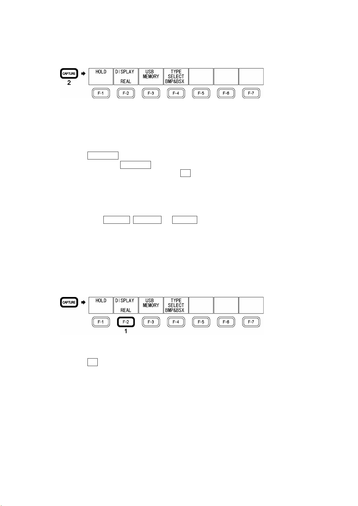
7. Screen Capture Feature
7.1 Taking a Screen Capture of the Display
To take a screen capture of the display, follow the procedure below.
Figure 7-2 Taking a screen capture of the display
1. Configure the LV 5330 so that the display that you want to capture appears on the screen.
Only measurement displays can be captured. The file list display and the USB memory
display cannot be captured.
2. Press CAPTURE.
When you press CAPTURE, the LV 5330 takes a screen capture of the display. You can
also take screen captures by pressing F•1 HOLD while the screen capture menu is
displayed.
Note that if you perform one of the following operations after capturing a display, the
captured data will be cleared.
• Change the display mode.
• Press SYSTEM, MEMORY, or RECALL.
• Turn off the power.
7.2 Displaying Screen Capture Data on the LV 5330
The data that you capture by following the procedure in section 7.1, “Taking a Screen Capture
of the Display,” can be displayed, or it can be overlaid on the current input signal. To display
or overlay the captured data, follow the procedure below.
Figure 7-3 Displaying screen capture data
1. Press F•2 DISPLAY, and select the display format.
The display formats that you can select are explained below.
REAL The input signal is displayed (this is the default setting).
HOLD The screen capture data is displayed.
BOTH The input signal and the captured data are displayed on top of each other
You can display the captured data of video signal waveforms, vectors, and pictures on
the LV 5330. Other kinds of data (CINELITE, CINEZONE, status, audio meter, and 5-bar)
cannot be displayed. However, these other kinds of data can be saved to USB memory
as BMP files.
For details, see section
with their intensities halved.
7.3, “Saving Screen Capture Data to USB Memory.”
7-2
Page 56

7. Screen Capture Feature
7.3 Saving Screen Capture Data to USB Memory
The data that you capture by following the procedure in section 7.1, “Taking a Screen Capture
of the Display,” is cleared when operations such as changing the display mode are performed.
However, you can display the captured data on the LV 5330 even after the power has been
turned off by saving it to USB memory (if you save it in BSX format).
You can also view captured data on a PC (if you save it in BMP format).
If you set SHORTCUT KEY SET in the system settings to CAP USB, you can save the
current display to USB memory simply by pressing SHORT CUT.
Reference: SHORTCUT KEY SET → Section 5.6, “Assigning a Function to the SHORT CUT Key”
Figure 7-4 Saving screen capture data
1. Press F•4 TYPE SELECT to select the file format that you want to save the screen
capture data in.
The file formats that you can select are explained below.
BMP&BSX The screen capture data is saved to a BMP file and a BSX file in the USB
memory. You can view the saved data on a PC or on the LV 5330. This is
the default setting.
BMP The screen capture data is saved to a BMP file in the USB memory.
You can view the saved data on a PC.
BSX The screen capture data is saved to a BSX file in the USB memory.
You can view the saved data on the LV 5330.
2. Press F•3 USB MEMORY.
The file list display appears.
3. Press F•1 STORE USB.
The captured data is saved to the USB memory.
The file name is automatically set to “CAP” + the date and time that have been set using
the system settings.
The date is written using the format that has been specified in the system settings. The
time is written in this order: hour, minute, second.
Example: CAP20080501100859.BMP
The file structure in the USB memory is shown below.
USB memory
BMP
└
├
└
CAP********hhmmss.BMP
CAP********hhmmss.BSX
7-3
Page 57

7. Screen Capture Feature
7.4 Viewing Screen Capture Data from USB Memory
The screen capture data that you save in BSX format by following the procedure in section
7.3, “Saving Screen Capture Data to USB Memory,” can be displayed, or it can be overlaid on
the current input signal. Screen capture data that has been saved in BMP format cannot be
displayed on the LV 5330.
Figure 7-5 Viewing screen capture data from USB memory
1. Press CAPTURE.
2. Press F•3 USB MEMORY.
The file list display appears.
3. Turn F•D to select the file number of the file you want to display.
4. Press F•4 RECALL USB.
F•4 RECALL appears when the selected file is a BSX file.
5. Press F•2 DISPLAY, and select the display format.
After you press F•4 RECALL USB, the display format is BOTH. For details about the
different display formats, see section 7.2, “Displaying Screen Capture Data on the LV
5330.”
7-4
Page 58

7. Screen Capture Feature
7.5 Deleting Screen Capture Data from USB Memory
To delete the screen capture data that you save by following the procedure in section 7.3,
“Saving Screen Capture Data to USB Memory,” follow the procedure below. You can also
delete screen capture data from USB memory using a PC.
Figure 7-6 Deleting screen capture data from USB memory
1. Press CAPTURE.
2. Press F•3 USB MEMORY.
The file list display appears.
3. Turn F•D to select the file number of the file you want to delete.
4. Press F•3 FILE DELETE.
5. Press F•1 DELETE YES.
To abort the deletion of the selected screen capture data file, press F•3 DELETE NO.
7-5
Page 59

8. Picture Display
8.1 Picture Display Explanation
To make the picture display appear, press PICTURE.
8. Picture Display
Figure 8-1 Picture display
Table 8-1 Picture display explanation
No. Item Explanation
1 Aspect marker You can display a marker for the selected aspect ratio in relation to the
frame.
Reference: Section
2 Safe action marker You can display a marker of a selected size in relation to the frame or
aspect marker.
Reference: Section
3 Safe title marker
4 Selected line You can display a marker on the selected line.
5 Center marker You can display a marker in the center of the picture that is 10 % the size
6 Brightness and
contrast display
You can display a marker of a selected size in relation to the frame or
aspect marker.
Reference: Section
Reference: Section
of the frame.
Reference: Section
The brightness and contrast of the picture are displayed. The brightness
and contrast can be adjusted at all levels of the picture display.
Reference: Section
8.3.1, “Displaying an Aspect Marker”
8.3.2, “Displaying a Safe Action Marker”
8.3.3, “Displaying a Safe Title Marker”
8.4, “Line Selection Settings”
8.3.4, “Displaying a Center Marker”
8.2, “Setting the Brightness and Contrast”
8-1
Page 60

8. Picture Display
8.2 Setting the Brightness and Contrast
You can set the brightness and contrast of the picture by using BRIGHT and CONT. The
brightness and contrast can be adjusted at all levels of the picture display. The current
brightness and contrast settings appear in the lower right of the display.
The settings made here do not affect the CINELITE display, CINEZONE display, or
multi-screen display.
8.2.1 Adjusting the Brightness
You can adjust the brightness of the picture by turning BRIGHT.
Pressing BRIGHT returns the brightness to its default setting (0 %).
Settings
Selectable range: –50 % to 50 % (The default value is 0 %.)
8.2.2 Adjusting the Contrast
You can adjust the contrast of the picture by turning CONT.
Pressing CONT returns the contrast to its default setting (100 %).
Settings
Selectable range: 50 % to 150 % (The default value is 100 %.)
8.3 Marker Settings
To configure marker settings, press F•1 MARKER in the picture menu. You can use the menu
that appears to configure the display settings for every type of marker.
The markers that you set here do not appear in the multi-screen display. F•1 MARKER
appears when SIZE is set to FIT.
Reference: SIZE → Section 8.5, “Selecting the Picture Display Size”
PICTURE → F•1 MARKER →
Figure 8-2 MARKER menu
8-2
Page 61

8.3.1 Displaying an Aspect Marker
To display an aspect marker, follow the procedure below.
Procedure
PICTURE → F•1 MARKER → F•1 ASPECT
Settings
2.35:1: A 2.35:1 aspect marker is displayed.
1.85:1: A 1.85:1 aspect marker is displayed.
1.66:1: A 1.66:1 aspect marker is displayed.
14:9: A 14:9 aspect marker is displayed.
13:9: A 13:9 aspect marker is displayed.
4:3: A 4:3 aspect marker is displayed.
This setting cannot be selected when the input signal is SD-SDI.
16:9: A 16:9 aspect marker is displayed.
This setting cannot be selected when the input signal is HD-SDI.
OFF: An aspect marker is not displayed. This is the default setting.
8. Picture Display
HD SD
Figure 8-3 Aspect markers
8.3.2 Displaying a Safe Action Marker
To display a safe action marker, follow the procedure below.
Procedure
PICTURE → F•1 MARKER → F•2 SAFE ACTION
Settings
95%: A safe action marker whose size is 95 % that of the frame (or aspect marker if
an aspect marker is being displayed) is displayed.
93%: A safe action marker whose size is 93 % that of the frame (or aspect marker if
an aspect marker is being displayed) is displayed.
90%: A safe action marker whose size is 90 % that of the frame (or aspect marker if
an aspect marker is being displayed) is displayed.
OFF: A safe action marker is not displayed. This is the default setting.
8-3
Page 62

8.3.3 Displaying a Safe Title Marker
To display a safe title marker, follow the procedure below.
Procedure
PICTURE → F•1 MARKER → F•3 SAFE TITLE
Settings
88%: A safe title marker whose size is 88 % that of the frame (or aspect marker if
an aspect marker is being displayed) is displayed.
80%: A safe title marker whose size is 80 % that of the frame (or aspect marker if
an aspect marker is being displayed) is displayed.
OFF: A safe title marker is not displayed. This is the default setting.
8.3.4 Displaying a Center Marker
To display a center marker, follow the procedure below.
The center marker is displayed in the center of the frame at 10 % of the frame’s size.
8. Picture Display
Procedure
PICTURE → F•1 MARKER → F•4 CENTER
Settings
ON: A center marker is displayed.
OFF: A center marker is not displayed. This is the default setting.
CENTER = ON
Figure 8-4 Center marker
8-4
Page 63

8. Picture Display
8.4 Line Selection Settings
To configure line selection settings, press F•2 LINE SELECT in the picture menu. The line
selection feature allows you to display a marker on the selected line.
The markers that you set here do not appear in the CINELITE or CINEZONE display.
F•2 LINE SELECT appears when SIZE is set to FIT.
Reference: SIZE → Section 8.5, “Selecting the Picture Display Size”
Figure 8-5 LINE SELECT menu
8.4.1 Displaying a Marker on the Selected Line
To display a marker on the selected line, follow the procedure below.
Changing this setting will also change the video signal waveform display and vector display
line selection settings.
Procedure
PICTURE → F•2 LINE SELECT → F•1 LINE SELECT
Settings
ON: A marker appears on the selected line.
OFF: A marker does not appear on the selected line. This is the default setting.
LINE SELECT = ON
Figure 8-6 Line select display
8-5
Page 64
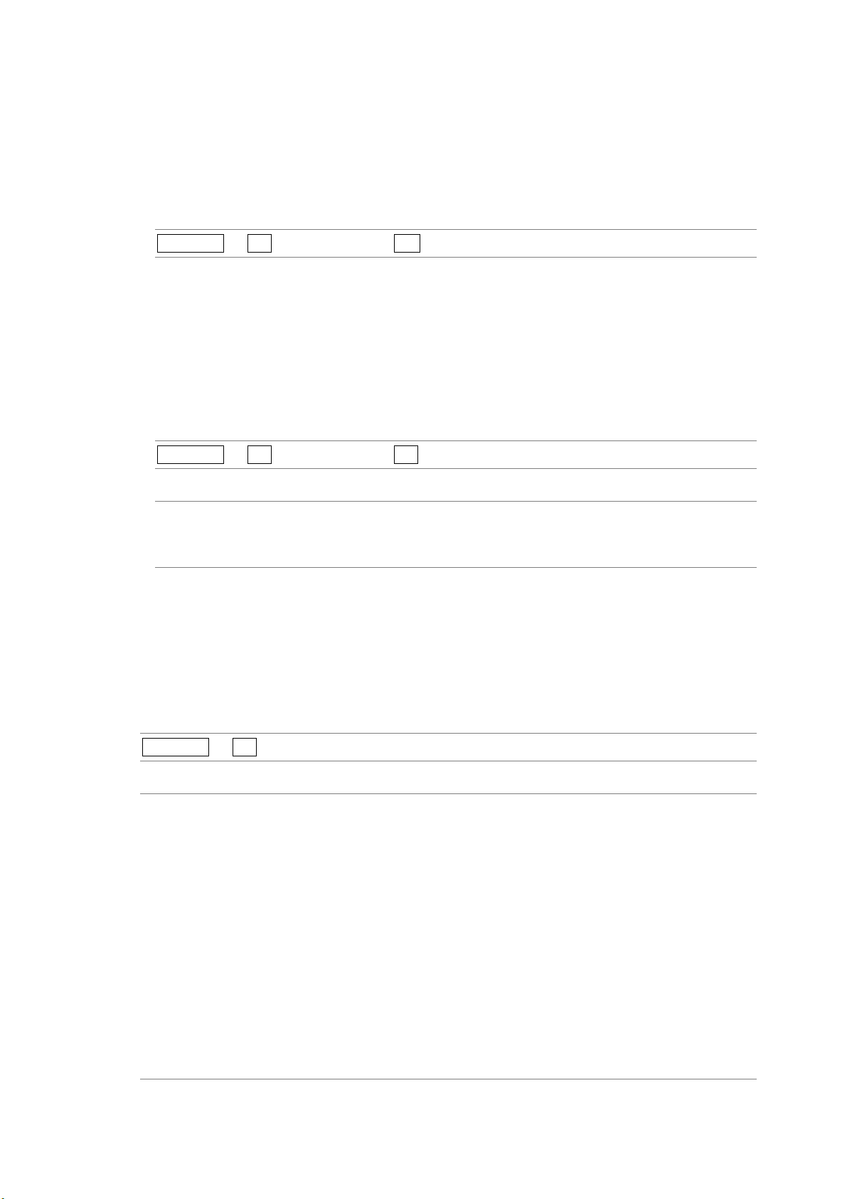
8. Picture Display
8.4.2 Selecting a Line
To select a line to display a marker on, follow the procedure below. The selected line is
indicated in the lower left of the display.
Changing this setting will also change the selected line in the CINELITE, video signal
waveform, vector, and status (data dump) displays.
Procedure
PICTURE → F•2 LINE SELECT → F•D
8.4.3 Setting the Line Selection Range
To set the line selection range, follow the procedure below.
The line selection range setting is valid when the input format is set to interlaced or
segmented frame. Changing this setting will also change the video signal waveform display
and vector display line selection ranges.
Procedure
PICTURE → F•2 LINE SELECT → F•2 FIELD
Settings (the examples are the selectable ranges when the input format is 1080i/59.94)
FIELD1: A line from field one can be selected. (Example: 1 to 563.)
FIELD2: A line from field 2 can be selected. (Example: 564 to 1125.)
FRAME: All lines can be selected. This is the default setting. (Example: 1 to 1125.)
8.5 Selecting the Picture Display Size
To set the picture display size, follow the procedure below.
Regardless of the setting made here, the picture is displayed using the FIT setting in the
CINELITE, CINEZONE, and multi-screen displays.
Procedure
PICTURE → F•3 SIZE
Settings
FIT: The picture size is adjusted to the most suitable size for the screen. This is the
default setting.
x1: A single sample of the video signal is displayed with a single pixel on the screen.
The marker and line select features cannot be used.
When the input signal is HD-SDI, you can use the control stick to adjust the
location of the picture. Approximately five seconds after the last operation is
performed, the menu and the information displays at the top of the screen
disappear. To redisplay the menu and information, perform some kind of operation.
x2: A single sample of the video signal is displayed with a four pixels on the screen.
The marker and line select features cannot be used.
You can use the control stick to adjust the location of the picture. Approximately
five seconds after the last operation is performed, the menu and the information
displays at the top of the screen disappear. To redisplay the menu and information,
perform some kind of operation.
8-6
Page 65

SIZE = FIT
8. Picture Display
SIZE = x1 SIZE = x2
Figure 8-7 Picture display sizes
8.6 Switching between the Color and Monochrome Displays
To switch between the color and monochrome displays, follow the procedure below.
Regardless of the setting made here, the picture is displayed using the COLOR setting in the
CINELITE, CINEZONE, and multi-screen displays.
Procedure
PICTURE → F•4 DISPLAY
Settings
COLOR: The picture is displayed in color. This is the default setting.
MONOCHRO: The picture is displayed in monochrome.
8-7
Page 66

8.7 Adjusting the Chroma Gain
To adjust the chroma gain, follow the procedure below. If you press F•D, the chroma gain will
be reset to its default value of 100.
This setting is available when F•4 DISPLAY is set to COLOR. Regardless of the setting made
here, the picture is displayed using a chroma gain of 100 in the CINELITE, CINEZONE, and
multi-screen displays.
Procedure
8. Picture Display
PICTURE → F•5 CHROMA%
Settings
Selectable range: 50 to 150 (The default setting is 100.)
8.8 Adjusting the Aperture
To adjust the aperture, follow the procedure below. A larger number will result in more
well-defined outlines. If you press F•D, the aperture will be reset to its default value of 0.
Procedure
PICTURE → F•6 APERTURE
Settings
Selectable range: 0 to 100 (The default setting is 0.)
APERTURE = 0 APERTURE = 100
Figure 8-8 Aperture settings
8-8
Page 67

9. CINELITE Display
9. CINELITE Display
In the CINELITE display, you can display the luminance levels of up to three points on the
picture that you have selected. To show the CINELITE display, press CINELITE.
9.1 Selecting the Points to Measure
The CINELITE display cannot be used with the multi-screen display.
CINELITE →
Figure 9-1 CINELITE menu
You can choose one of the following luminance level display formats.
• f Stop level (f Stop display)
→ Section
• Luminance level (percentage)
→ Section
• RGB level (percentage)
→ Section
• RGB level (256 levels)
→ Section
9.4, “Displaying Luminance Levels as f Stop Numbers”
9.5, “Displaying Luminance Levels as Percentages or RGB Values”
9.5, “Displaying Luminance Levels as Percentages or RGB Values”
9.5, “Displaying Luminance Levels as Percentages or RGB Values”
You can set up to three points to measure. To select which measurement point positions you
will specify with the cursor, follow the procedure below.
The F•2 MEAS POS settings in the menus accessed by pressing F•1 f Stop DISPLAY and
F•2 %DISPLAY are the same.
Procedure
CINELITE → F•1 f Stop DISPLAY → F•2 MEAS POS
→ F•2 %DISPLAY → F•2 MEAS POS
Settings
P1: You can use the cursor to select the position of measurement point 1. This is
the default setting.
P2: You can use the cursor to select the position of measurement point 2.
P3: You can use the cursor to select the position of measurement point 3.
9-1
Page 68

9.2 Moving the Cursors
To set a measurement point, you must select a measurement point by pressing F•2 MEAS
POS and then move the X and Y cursors to the point you want to measure. You can use the Y
cursor to select a line and the X cursor to select a sample. The X and Y cursors are not
displayed if they are within a blanking interval.
The measurement point settings made in the menus accessed by pressing F•1 f Stop
DISPLAY and F•2 %DISPLAY are the same. Changing the position of the Y cursor (LINE) will
also change the selected line in the picture, video signal waveform, vector, and status (data
dump) displays.
There are three different methods that you can use to move the cursors:
• V POS and H POS
Turn V POS clockwise to move the Y cursor (LINE) up. Press V POS to move the Y cursor to
the center of the picture.
Turn H POS clockwise to move the X cursor (SMPL) to the right. Press H POS to move the X
cursor to the center of the picture.
• Control Stick
9. CINELITE Display
Push the control stick up to move the Y cursor (LINE) up.
Push the control stick to the right to move the X cursor (SMPL) to the right.
You can move diagonally when you use the control stick. Also, you can move quickly by
pushing down on the control stick before moving it in the desired direction.
• F•D
You can move the cursors by turning F•D. You can toggle between the LINE and SAMPLE
cursors by pressing F•D.
The F•1 F.D settings in the menus accessed by pressing F•1 f Stop DISPLAY and
F•2 %DISPLAY are the same.
Procedure
CINELITE → F•1 f Stop DISPLAY → F•1 F.D
→ F•2 %DISPLAY → F•1 F.D
Settings
LINE: You can move the Y cursor (LINE) up by turning F•D clockwise. This is the
default setting.
SAMPLE: You can move the X cursor (SMPL) to the right by turning F•D clockwise.
9-2
Page 69
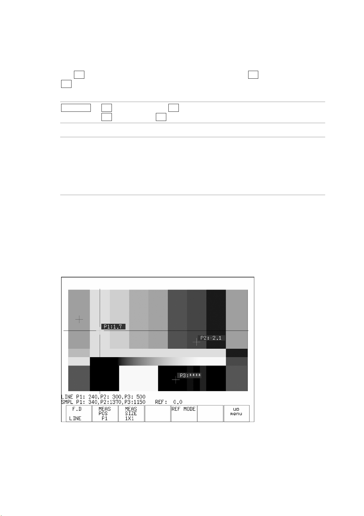
9. CINELITE Display
9.3 Selecting the Measurement Area
To select the area of luminance measurement, follow the procedure below. This setting is
applied to P1 to P3 and REF.
The F•3 MEAS SIZE settings in the menus accessed by pressing F•1 f Stop DISPLAY and
F•2 %DISPLAY are the same.
Procedure
CINELITE → F•1 f Stop DISPLAY → F•3 MEAS SIZE
→ F•2 %DISPLAY → F•3 MEAS SIZE
Settings
1X1: The single pixel at the intersection of the cursors is measured. This is the
default setting.
3X3: The luminance of the 3×3 area of pixels centered around the pixel at the
intersection of the cursors is averaged and measured.
9X9: The luminance of the 9×9 area of pixels centered around the pixel at the
intersection of the cursors is averaged and measured.
9.4 Displaying Luminance Levels as f Stop Numbers
In the f Stop display, the f Stop values relative to the reference position are displayed.
Typically, 18 % gray is used in the reference position.
The measured values are typically displayed using white, but they are displayed using yellow
when the luminance level is 80 % or more. Luminance levels of 0 % or less cannot be
measured. They are displayed in yellow as “****”.
Figure 9-2 f Stop display
9-3
Page 70

9. CINELITE Display
To display luminance levels as f Stop numbers using 18 % gray as the reference position,
follow the procedure below. Include an 18 % gray chart with the objects that you are filming.
Figure 9-3 f Stop display
1. Press CINELITE.
2. Press F•6 GAMMA to select a gamma correction table.
The default gamma correction value is 0.45, but you can also use a user-defined gamma
correction table that matches the gamma characteristics of the camera that you are
using. For details, see section
9.6, “Configuring User-Defined Correction Tables”
3. Press F•1 f_Stop DISPLAY.
4. Press F•5 REF MODE.
Cursors for setting the reference position appear. The cursors are not displayed if they
are within the blanking interval.
5. Place the cursors over the 18 % gray area.
Reference: Section 9.2, “Moving the Cursors”
6. Press F•6 REF SET.
The f Stop value for 18 % gray becomes 0.0, and is displayed at the bottom of the screen
next to “REF:”. The reference position is displayed with a red cursor.
This option becomes available after you press F•5 REF MODE.
7. Use the cursors to set the measurement point.
The f Stop value relative to 18 % gray appears next to the cursors.
9-4
Page 71

9. CINELITE Display
9.5 Displaying Luminance Levels as Percentages or RGB Values
In the percentage and RGB display, you can display luminance levels as level percentages,
RGB percentages, or using 255 RGB levels. The measured values are typically displayed
using white, but they are displayed using yellow when the luminance level is 80 % or more or
0 % or less.
• LEVEL% display
Luminance levels are indicated as percentages. This is the default setting.
Figure 9-4 LEVEL% display
• RGB% display
Each R, G, and B luminance level is indicated using a percentage. The levels are also
indicated using bars on the left side of the display (the order is R, G, and then B).
Figure 9-5 RGB% display
9-5
Page 72

9. CINELITE Display
• RGB 255 display
The RGB levels are displayed using 256 steps from 0 to 255. The levels are also indicated
using bars on the left side of the display (the order is R, G, and then B).
The value of an RGB level that is 100 % or greater is 255. The value of an RGB level that is
0 % or less is 0.
Figure 9-6 RGB 255 display
To display luminance levels as percentages or RGB levels, follow the procedure below.
Figure 9-7 Percentage and RGB display
1. Press CINELITE.
2. Press F•2 %DISPLAY.
3. Press F•3 %/RGB, and select the display format.
You can select LEVEL%, RGB%, or RGB 255.
4. Use the cursors to set the measurement point.
The measured values appear near the cursors in the format that you selected in step 3.
The cursors are not displayed if they are within the blanking interval.
Reference: Section 9.2, “Moving the Cursors”
9-6
Page 73

9. CINELITE Display
9.6 Configuring User-Defined Correction Tables
The default gamma correction value when measuring f Stop levels is 0.45, but you can also
use a user-defined gamma correction table that matches the gamma characteristics of the
camera that you are using.
There are two types of user-defined correction tables. The first type includes USER-1 to
USER-3 and consists of tables that are created using the LV 5330. The second type includes
USER-A to USER-E and consists of tables that have been created externally using a device
such as a PC. Neither type of user-defined correction table is deleted if you initialize the LV
5330 by following the procedure in section
9.6.1 Creating User-Defined Correction Tables Using the LV 5330
You can create and store up to three user-defined correction tables on the LV 5330.
To create a user-defined correction table, prepare a grayscale chart for which the camera f
Stop values vary by one for each step, and follow the procedure below.
5.7.1, “Initializing the Settings Using SETUP INIT.”
Figure 9-8 Creating user-defined correction tables
1. Press CINELITE.
2. Press F•6 GAMMA, and select USER-1.
In this example, the table for USER-1 is created, but the tables for USER-2 and
USER-3 can also be created in the same way.
3. Press F•7 CAL.
When you press F•7 CAL, a user-defined correction table appears in the bottom left of
the screen, and the luminance (the data dump Y value) appears near the intersection
of the X and Y cursors.
This setting is available when F•6 GAMMA is set to an option other than 0.45.
9-7
Page 74

9. CINELITE Display
Figure 9-9 User-defined correction table creation display
4. Press F•2 TABLE CLEAR.
All of the values in the user-defined correction table that is currently being edited are
initialized. Be sure to initialize the values first when you create a new user-defined
correction table.
5. Move the X and Y cursors to the darkest part of the grayscale chart.
As you repeat this step and the ones that follow, move the X and Y cursors up
step-by-step.
6. Press F•5 CAL F, and turn F•D to select 22.0.
As you repeat this step, change the value that you select from 22.0 to 16.0 to 11.0 to
8.0 to 5.6 to 4.0 to 2.8 to 2.0, in that order.
7. Press F•4 CAL SET.
The location in the user-defined correction table specified using F•5 CAL F is set to the
luminance at the intersection of the X and Y cursors. To delete a line of data, press F•3
DATA CLEAR.
8. Repeat steps 5 through 7 to input Lev values into the user-defined correction table.
Make sure that the Lev value increases for each new step. Do not leave any Lev
settings in the table blank.
9-8
Page 75

9. CINELITE Display
The REF value in the user-defined correction table is entered when you press F•6 REF
SET in the f Stop display.
For example, if you use the table shown below and press F•6 REF SET when the
luminance at the intersection of the X and Y cursors (the data dump Y value) is 416, the f
Stop value at that point (3.0) is displayed as the REF value.
→
Figure 9-10 User-defined correction table
The f Stop value that corresponds to the luminance at the intersection of the X and Y
cursors when F•6 REF SET is pressed is 0. The other f Stop values are indicated below.
The values between specified values are interpolated linearly.
When Lv = 152 f Stop = 0.0 - 3.0 = –3.0
When Lv = 240 f Stop = 1.0 - 3.0 = –2.0
When Lv = 328 f Stop = 2.0 - 3.0 = –1.0
When Lv = 416 f Stop = 3.0 - 3.0 = 0.0
When Lv = 504 f Stop = 4.0 - 3.0 = 1.0
When Lv = 592 f Stop = 5.0 - 3.0 = 2.0
When Lv = 680 f Stop = 6.0 - 3.0 = 3.0
When Lv = 768 f Stop = 7.0 - 3.0 = 4.0
9-9
Page 76

9. CINELITE Display
9.6.2 Loading a User-Defined Correction Table into the LV 5330
You can load up to five user-defined correction tables into the LV 5330.
To load a user-defined correction table into the LV 5330, follow the procedure below.
Figure 9-11 Loading user-defined correction tables
1. Create a user-defined correction table.
Example (TEST.CLT):
#################################
NAME:SAMPLE_1
TYPE:0
#Input –7% 0
# 109% 4095
#Output 0% 0
# 1000% 65535
#Input Output
#################################
0 0
1 16
2 32
(Omitted)
4093 65488
4094 65504
4095 65520
# EOF
················ Comment
················ Keyword
················ Keyword
················ Comment
················ Comment
················ Comment
················ Comment
················ Comment
················ Comment
················ Data
················ Data
················ Data
················ Data
················ Data
················ Data
················ Comment
9-10
Page 77

9. CINELITE Display
When you create a correction table, make sure that it conforms to the specifications
listed below.
Overall File Specifications
File Type ASCII text file
Extension .CLT
End-of-Line Character CR+LF
Number of Lines 5000 or less
Number of Characters per Line 255 or less (including CR+LF)
File Name Length 20 characters or less (excluding the extension)
Permitted File Name Characters Letters of the alphabet (A to Z; uppercase and
lowercase), numerals (0 to 9), and underscores
(_).
Comment Specifications
If you start a line with the number sign (#), the line is treated as a comment and does
not affect operations.
You can put comments anywhere.
Keyword Specifications
Be sure to put the keyword lines before the data lines and to enter a keyword without
anything preceding it at the beginning of each keyword line.
NAME: The LV 5330 displays the eight characters that follow the separator
(colon) as the name of the correction table. After the separator, enter the
correction table name using letters of the alphabet (A to Z; uppercase and
lowercase), numbers (0 to 9), and underscores (_). You can enter up to 10
characters.
TYPE: This is a code for identifying the file type. Enter a zero after the separator
(colon).
Data Specifications
From the start of a line, enter the input value, a separator, and then the output value, in
that order.
Input Value Enter values from 0 to 4095 (12 bits), increasing the value by one for
each line.
A luminance level of 100 % is defined as
940 (10 bits) × 4 = 3760 (12 bits).
A luminance level of 0 % is defined as
64 (10 bits) × 4 = 256 (12 bits).
Separator Enter a single tab code.
Output Value Enter a value from 0 to 65535 (16 bits).
2. Save the user-defined correction table to USB memory, and connect the USB memory
to the LV 5330.
Save the user-defined correction table in the USB memory’s root directory.
3. Press CINELITE.
4. Press F•6 GAMMA, and select USER-A.
In this example, a user-defined correction table is assigned to USER-A, but
user-defined correction tables can be assigned to USER-B through USER-E in the
same way.
5. Press F•7 CAL.
To clear the previous USER-A table, press F•3 TABLE CLEAR.
This setting is available when F•6 GAMMA is set to an option other than 0.45.
9-11
Page 78

6. Press F•1 FILE.
The file list display appears.
9. CINELITE Display
Figure 9-12 File list display
7. Turn the function dial to select the file in the USB memory that you want to copy from.
8. Press F•2 COPY.
The user-defined correction table from the USB memory that you selected is copied to
USER-A. When F•2 COPY disappears, the copy operation is complete. If a file had
already been copied to the selected table number (USER-A in this example), the
previous file is overwritten.
To clear the table that has been copied to USER-A, press F•3 TABLE CLEAR.
When you press F•6 GAMMA in the CINELITE menu, the user-defined correction tables
that have been loaded from USB memory appear. A loaded correction table is displayed
using the name determined by its NAME keyword.
Figure 9-13 CINELITE menu
9-12
Page 79

10. CINEZONE Display
The CINEZONE display has a CINEZONE display mode, in which the picture luminance levels
are displayed using colors, and a level search display mode, in which the specified luminance
level is displayed using green.
Both of these display modes can be accessed by pressing CINEZONE. Neither of them can be
incorporated into the multi-screen display.
10.1 CINEZONE Display
10. CINEZONE Display
Press CINEZONE to show the CINEZONE display.
Picture display
CINEZONE display
Figure 10-1 CINEZONE display
10-1
Page 80

In the CINEZONE display, the picture luminance levels are converted into RGB colors.
Also, luminance levels above F•5 UPPER% are displayed using white, and levels below F•6
LOWER% are displayed using black. You can see what colors correspond to what luminance
levels by looking at the scale on the right of the display.
10.1.1 Selecting the Color Gradation
To select the color gradation, follow the procedure below.
Procedure
10. CINEZONE Display
CINEZONE → F•4 DISPLAY
Settings
LINEAR: Luminance values from 0 to 100 % are displayed using 1024 different colors.
This is the default setting.
STEP: Values below 0 %, from 0 to 100 % (in 10 % steps), and above 100 % are
displayed using 12 different colors.
DISPLAY = LINEAR DISPLAY = STEP
10.1.2 Setting the Color Range
Figure 10-2 Color gradations
Luminance levels in the CINEZONE display are typically displayed using their
corresponding colors, but luminance levels above F•5 UPPER% are displayed using white,
and levels below F•6 LOWER% are displayed using black.
If F•5 UPPER% is 1 % greater than F•6 LOWER% and you lower the value of F•5
UPPER%, the value of F•6 LOWER% is automatically lowered to maintain a difference of
1 % between the two values. In the same way, if you raise the value of F•6 LOWER%, the
value of F•5 UPPER% is automatically raised to maintain a difference of 1 % between the
two values.
To set the color range, follow the procedure below.
Procedure
CINEZONE → F•5 UPPER%
→ F•6 LOWER%
Settings
Range for UPPER%: –6.3 to 109.4 (The default setting is 95.0.)
Range for LOWER%: –7.3 to 108.4 (The default setting is 5.0.)
10-2
Page 81

10.2 Level Search Display
In the level search display, the specified luminance level ±0.5 % is displayed using green on
an otherwise monochrome picture display.
To set the luminance level that is displayed using green, follow the procedure below.
Procedure
10. CINEZONE Display
CINEZONE →
SEARCH →
F•3
F•1
LEVEL%
Settings
Selectable range: –7.3 to 109.4 (The default setting is 0.0.)
Figure 10-3 Level search display
10-3
Page 82

11. Video Signal Waveform Display
11. Video Signal Waveform Display
11.1 Video Signal Waveform Display Explanation
To view the video signal waveform display, press WFM.
Figure 11-1 Video signal waveform display
Table 11-1 Video signal waveform display explanation
No. Item Explanation
1 Filter Appears when you have set a low pass filter.
Reference:
2 Gain The video signal waveform gain is displayed here. You can set the gain to
a value between 0.2 and 10 by setting GAIN MAG and GAIN VARIABLE.
Reference:
3 Scale for 75 %
color bars
4 Cursor You can measure the time or amplitude using cursors.
5 Selected line You can display the waveform of the selected line.
A scale that matches the peak levels of the chroma of a 75 % color bar
test signal can be displayed here.
Reference:
Reference:
Reference:
Section 11.4.3, “Selecting a Filter”
Section 11.4.1, “Selecting the Fixed Gain,” section 11.4.2
“Setting the Variable Gain”
Section 11.9.2, “Displaying a Scale for 75 % Color Bars”
Section 11.7, “Cursor Settings”
Section 11.6, “Line Selection Settings”
11-1
Page 83

11. Video Signal Waveform Display
11.2 Display Position Settings
You can adjust the display position of a video signal waveform using V POS and H POS.
11.2.1 Setting the Vertical Position
Turn V POS to set the video signal waveform’s vertical position.
Pressing V POS will return the vertical display position to its default location.
11.2.2 Setting the Horizontal Position
Turn H POS to set the video signal waveform’s horizontal position.
Pressing H POS will return the horizontal display position to its default location.
11.3 Intensity Settings
To configure the intensity settings, press F•1 INTEN in the video signal waveform menu. You
can set the video signal waveform and scale intensities.
WFM → F•1 INTEN →
Figure 11-2 INTEN menu
11.3.1 Setting the Video Signal Waveform Intensity
To set the video signal waveform intensity, follow the procedure below. Regardless of this
setting, in the multi-screen display, waveforms are displayed using the intensity that MULTI
WFM is set to. The WFM INTEN value set using MULTI WFM and the VECTOR INTEN
value set using MULTI VEC are the same.
If you press F•D, the intensity will be reset to its default value of 0.
Reference: MULTI WFM → Section 16.2, “Setting Each Measurement Mode”
Procedure
WFM → F•1 INTEN → F•1 WFM INTEN
Settings
Selectable range: –128 to 127 (The default value is 0.)
11-2
Page 84

11. Video Signal Waveform Display
11.3.2 Setting the Scale Intensity
To set the scale intensity, follow the procedure below. Regardless of this setting, in the
multi-screen display, scales are displayed using the intensity that MULTI WFM is set to.
The SCALE INTEN value set using MULTI WFM and the SCALE INTEN value set using
MULTI VEC are the same.
If you press F•D, the scale intensity will be reset to its default value of 4.
Reference: MULTI WFM → Section 16.2, “Setting Each Measurement Mode”
Procedure
WFM → F•1 INTEN → F•2 SCALE INTEN
Settings
Selectable range: –8 to 7 (The default setting is 4.)
11.4 Gain and Filter Settings
To configure gain and filter settings, press F•2 GAIN FILTER in the video signal waveform
menu. You can configure the video signal waveform gain and filter.
WFM → F•2 GAIN FILTER →
Figure 11-3 GAIN FILTER menu
11.4.1 Selecting the Fixed Gain
To set the fixed video signal waveform gain, follow the procedure below.
Procedure
WFM → F•2 GAIN FILTER → F•2 GAIN MAG
Settings
X1: No gain. This is the default setting.
X5: Waveforms are magnified to five times their normal size.
11-3
Page 85

11.4.2 Setting the Variable Gain
To set the variable video signal waveform gain, follow the procedure below.
You can set the video signal waveform gain to a value between 0.2 and 10 by setting F•2
GAIN MAG and F•1 GAIN VAR.
Procedure
11. Video Signal Waveform Display
WFM → F•2 GAIN FILTER → F•1 GAIN VAR
Settings
CAL: The video signal waveform gain is fixed. This is the default setting.
VAR: You can adjust the video signal waveform gain using F•D as described below.
The gain value appears in the upper right of the screen. If you press F•D, the
gain is set to its default value of 1.000 or 5.000.
0.200 to 2.000 (when GAIN MAG is ×1)
1.000 to 10.000 (when GAIN MAG is ×5)
GAIN MAG = ×1 GAIN MAG = ×5
GAIN VAR = VAR GAIN VAR = CAL
11.4.3 Selecting a Filter
To select a filter, follow the procedure below.
The filters that you can select vary depending on how COLOR MATRIX is set.
Reference: COLOR MATRIX → Section 11.8.1, “Selecting the Display Format”
Procedure
WFM → F•2 GAIN FILTER → F•3 FILTER
Figure 11-4 Video signal waveform gain
11-4
Page 86

11. Video Signal Waveform Display
• When COLOR MATRIX is set to Y,CB,CR; GBR; or RGB
Settings
FLAT: This filter has a flat frequency response over the entire bandwidth of the input
signal. This is the default setting.
LOW PASS: This filter is a low-pass filter with the following frequency responses:
Attenuation of 20 dB or more at 20 MHz when the input signal is HD-SDI
Attenuation of 20 dB or more at 3.8 MHz when the input signal is SD-SDI
FILTER = FLAT FILTER = LOW PASS
Figure 11-5 Component signal filter displays
• When COLOR MATRIX is set to COMPOSIT
Settings
FLAT: Only the pseudo-composite signal is displayed. This is the default setting.
FLAT+LUM: The pseudo-composite signal and the luminance signal are displayed side by
side.
FILTER = FLAT FILTER = FLAT+LUM
Figure 11-6 Pseudo-composite signal filter display
11-5
Page 87

11. Video Signal Waveform Display
11.5 Sweep Settings
To configure the video signal waveform sweep settings, press F•3 SWEEP in the video signal
waveform menu.
WFM → F•3 SWEEP →
Figure 11-7 SWEEP menu
11.5.1 Selecting the Sweep Method
To select a video signal waveform sweep method, follow the procedure below.
This setting is available when MODE is set to OVERLAY or PARADE. When MODE is set
to TIMING, the sweep mode setting is fixed at H.
Reference: MODE → Section 11.12, “Switching the Display Mode”
Procedure
WFM → F•3 SWEEP → F•1 SWEEP
Settings
H: Lines are displayed. This is the default setting.
V: Fields are displayed when the input format is interlaced or segmented frame.
Frames are displayed when the input format is progressive or when F•2
V_SWEEP is set to 2V.
SWEEP = H H_SWEEP = V
Figure 11-8 Sweep methods
11-6
Page 88

11. Video Signal Waveform Display
11.5.2 Selecting the Line Display Sweep Time
To select the line display sweep time, follow the procedure below.
This setting is available when F•1 SWEEP is set to H and COLOR MATRIX is set to
COMPOSIT or when F•1 SWEEP is set to H and MODE is set to OVERLAY. When MODE
is set to PARADE, the sweep mode setting is fixed at 1H.
Reference: COLOR MATRIX → Section 11.8.1, “Selecting the Display Format”
MODE → Section
11.12, “Switching the Display Mode”
Procedure
WFM → F•3 SWEEP → F•2 H_SWEEP
Settings
1H: The sweep time is set to that of one line. This is the default setting.
2H: The sweep time is set to that of two lines.
H_SWEEP = 1H H_SWEEP = 2H
Figure 11-9 Line display sweep times
11.5.3 Selecting the Field or Frame Display Sweep Time
To select the field or frame display sweep time, follow the procedure below.
This setting is available when F•1 SWEEP is set to V and the input format is set to
interlaced or segmented frame (as long as MODE is set to PARADE and COLOR MATRIX
is set to COMPOSIT).
When the input format is progressive, the sweep time is fixed at one frame. The sweep
time is fixed at 1V unless MODE is set to PARADE and COLOR MATRIX is set to
COMPOSIT.
Reference: COLOR MATRIX → Section 11.8.1, “Selecting the Display Format”
MODE → Section
11.12, “Switching the Display Mode”
Procedure
WFM → F•3 SWEEP → F•2 V_SWEEP
Settings
1V: The sweep time is set to that of one field. This is the default setting.
2V: The sweep time is set to that of one frame.
11-7
Page 89

11. Video Signal Waveform Display
V_SWEEP = 1V V_SWEEP = 2V
Figure 11-10 Field/frame display sweep times
11.5.4 Selecting Which Field to Display
When displaying fields, follow the procedure below to select which field to display.
This setting is available when F•1 SWEEP is set to V and the input format is set to
interlaced or segmented frame. However, this setting is invalid when F•2 V_SWEEP is set
to 2V.
Procedure
WFM → F•3 SWEEP → F•3 FIELD
Settings
FIELD1: Field 1 is displayed. This is the default setting.
FIELD2: Field 2 is displayed.
11.5.5 Selecting the Horizontal Magnification
To select the horizontal magnification, follow the procedure below. The magnifications that
you can select vary depending on the F•1 SWEEP, COLOR MATRIX, MODE, and F•2
H_SWEEP settings as indicated in the table below. When F•1 SWEEP is set to H and
COLOR MATRIX is set to COMPOSIT, the magnification is fixed at ×1.
Reference: COLOR MATRIX → Section 11.8.1, “Selecting the Display Format”
MODE → Section
11.12, “Switching the Display Mode”
Table 11-2 Horizontal magnifications
SWEEP COLOR MATRIX MODE H_SWEEP ×1 ×10 ×20 ×40 ACTIVE BLANK
H YCbCr PARADE — Yes Yes Yes No Yes Yes
GBR O V E RL AY 1H Yes Ye s Ye s No Yes Ye s
RGB 2H Yes Yes Yes No No Yes
TIMING — Yes Yes Yes No Yes No
V — — — Yes No Yes Yes No No
11-8
Page 90

Procedure
11. Video Signal Waveform Display
WFM → F•3 SWEEP → F•4 SWEEP MAG
Settings
X1: The video signal waveforms are displayed so that they fit in the screen. This
is the default setting.
X10: The video signal waveforms are magnified from the center of the display to
10 times the size of ×1.
X20: The video signal waveforms are magnified from the center of the display to
20 times the size of ×1.
X40: The video signal waveforms are magnified from the center of the display to
40 times the size of ×1.
ACTIVE: Everything but the video signal waveform blanking interval is magnified.
BLANK: The video signal waveform blanking interval is magnified.
SWEEP MAG = ×1 SWEEP MAG = ×10
SWEEP MAG = ACTIVE SWEEP MAG = BLANK
Figure 11-11 Horizontal magnifications
11-9
Page 91

11. Video Signal Waveform Display
11.6 Line Selection Settings
To configure the line select settings, press F•4 LINE SELECT in the video signal waveform
menu. You can display the waveform of the selected line.
WFM → F•4 LINE SELECT →
Figure 11-12 LINE SELECT menu
11.6.1 Displaying the Waveform of the Selected Line
To display the waveform of the selected line, follow the procedure below.
Changing this setting will also change the picture display and vector display line selection
settings.
Procedure
WFM → F•4 LINE SELECT → F•1 LINE SELECT
Settings
ON: The waveform of the selected line is displayed.
OFF: The waveforms of all lines are displayed on top of each other. This is the
default setting.
LINE SELECT = ON LINE SELECT = OFF
Figure 11-13 Turning line selection on and off
11.6.2 Selecting a Line
To select a line to display the waveform of, follow the procedure below. The selected line is
indicated in the lower left of the display.
Changing this setting will also change the selected line in the picture, CINELITE, vector,
and status (data dump) displays.
Procedure
WFM → F•4 LINE SELECT → F•D
11-10
Page 92
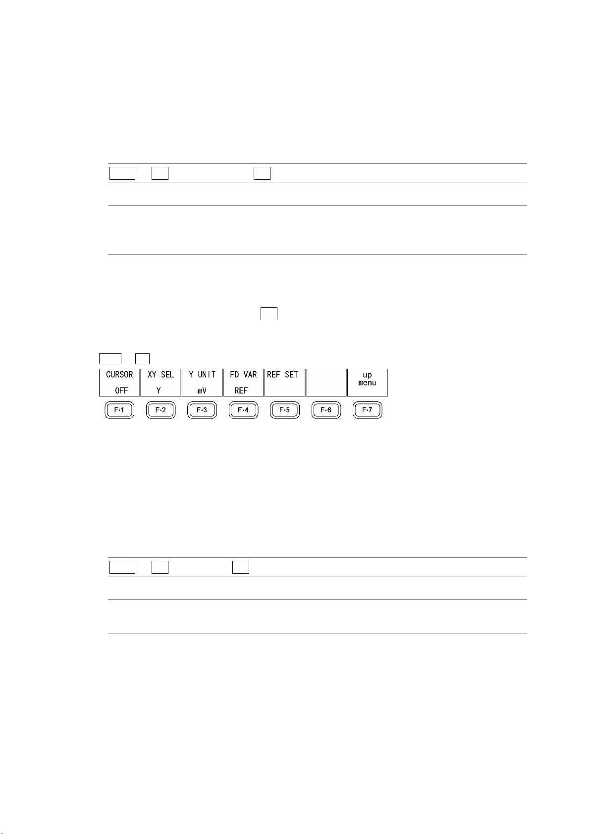
11. Video Signal Waveform Display
11.6.3 Setting the Line Selection Range
To set the line selection range, follow the procedure below.
The line selection range setting is valid when the input format is set to interlaced or
segmented frame. Changing this setting will also change the picture display and vector
display line selection ranges.
Procedure
WFM → F•4 LINE SELECT → F•2 FIELD
Settings (the examples are the selectable ranges when the input format is 1080i/59.94)
FIELD1: A line from field one can be selected. (Example: 1 to 563.)
FIELD2: A line from field 2 can be selected. (Example: 564 to 1125.)
FRAME: All lines can be selected. This is the default setting. (Example: 1 to 1125.)
11.7 Cursor Settings
To configure cursor settings, press F•5 CURSOR in the video signal waveform menu. You
can display cursors and use them to make measurements.
WFM → F•5 LINE SELECT →
Figure 11-14 CURSOR menu
11.7.1 Displaying Cursors
To display cursors, follow the procedure below.
The REF cursor is displayed in blue, and the DELTA cursor is displayed in green. The
measured value of DELTA-REF is displayed in the bottom right of the screen.
Procedure
WFM → F•5 CURSOR → F•1 CURSOR
Settings
ON: Cursors are displayed.
OFF: Cursors are not displayed. This is the default setting.
11-11
Page 93

11. Video Signal Waveform Display
11.7.2 Selecting the Cursor Type
To select the cursor type, follow the procedure below.
This setting is available when COLOR MATRIX is set to an option other than COMPOSIT.
When COLOR MATRIX is set to COMPOSIT, the cursor type setting is fixed at Y.
Procedure
WFM → F•5 CURSOR → F•2 XY SEL
Settings
X: X cursors are displayed for measuring time.
Y: Y cursors are displayed for measuring amplitude.
CURSOR = X CURSOR = Y
11.7.3 Moving the Cursors
Figure 11-15 Cursor types
Follow the procedure below to select a cursor and then move it by turning F•D. Triangles
appear on both ends of the selected cursor.
You can also select a cursor by pressing F•D. Each time you press F•D, the selected
cursor switches from REF, to DELTA, to TRACK, and so on.
Procedure
WFM → F•5 CURSOR → F•4 FD VAR
Settings
REF: The REF cursor (blue) is selected. This is the default setting.
DELTA: The DELTA cursor (green) is selected.
TRACK: The REF cursor and DELTA cursor are both selected.
11-12
Page 94

11. Video Signal Waveform Display
11.7.4 Setting the Units of Measurement
To select the units used in cursor measurement, follow the procedure below.
• When CURSOR is set to Y
Procedure
WFM → F•5 CURSOR → F•3 Y UNIT
Settings
mV: Measurements are made in units of voltage.
This setting cannot be chosen when COLOR MATRIX is set to COMPOSIT.
This is the default setting.
%: Measurements are made as percentages.
When COLOR MATRIX is set to YCbCr, GBR, or RGB 700 mV = 100 %
When COLOR MATRIX is set to COMPOSIT and the composite format is set
to NTSC 714 mV = 100 %
When COLOR MATRIX is set to COMPOSIT and the composite format is set
to PAL 700 mV = 100 %
R%: The amplitude will be measured as a percentage of the amplitude at the time
when you pressed F•5 REF SET.
This setting cannot be chosen when COLOR MATRIX is set to COMPOSIT.
• When CURSOR is set to X
Procedure
WFM → F•5 CURSOR → F•3 X UNIT
Settings
sec: Measurements are made in units of seconds. This is the default setting.
Hz: Measurements are made in units of frequency, with the length of one period
set to the distance between the two cursors.
11.7.5 Setting the Base Value
When F•3 Y UNIT is set to R%, follow the procedure below to set the amplitude at the
location of your choice to 100 %.
Procedure
WFM → F•5 CURSOR → F•5 REF SET
11-13
Page 95

11. Video Signal Waveform Display
11.8 Color System Settings
To configure the color system settings, press F•6 COLOR SYSTEM in the video signal
waveform menu. You can set the video signal waveform display format and setup level.
WFM → F•6 COLOR SYSTEM →
Figure 11-16 COLOR SYSTEM menu
11.8.1 Selecting the Display Format
To select a video signal waveform display format, follow the procedure below. The selected
display format is indicated in the upper left of the display.
If you select COMPOSIT, choose the composite display format (NTSC or PAL) by setting
COMPOSIT FORMAT in the system settings.
Reference: COMPOSIT FORMAT → Section 5.1.4, “Setting the Composite Display Format”
Procedure
WFM → F•6 COLOR SYSTEM → F•1 COLOR MATRIX
Settings
YCbCr: Luminance and chrominance signals are displayed. This is the default
setting.
GBR: A Y,C
RGB: A Y,C
COMPOSIT: A Y,C
B,CR signal is converted into a GBR signal and displayed.
B,CR signal is converted into an RGB signal and displayed.
B,CR signal is converted into a pseudo-composite signal and displayed.
COLOR MATRIX = YCbCr COLOR MATRIX = GBR
11-14
Page 96

11. Video Signal Waveform Display
COLOR MATRIX = RGB COLOR MATRIX = COMPOSIT
Figure 11-17 Component and pseudo-composite displays
11.8.2 Displaying the GBR or RGB Signal Simultaneously with the Luminance Signal
To display the GBR or RGB signal simultaneously with the luminance signal, follow the
procedure below.
The selected display format is indicated in the upper right of the display.
This setting is available when F•1 COLOR MATRIX is set to GBR or RGB.
Procedure
WFM → F•6 COLOR SYSTEM → F•2 YGBR
→ F•2 YRGB
Settings
ON: The GBR or RGB signal is displayed simultaneously with the luminance
signal.
OFF: The GBR or RGB signal is displayed by itself. This is the default setting.
YGBR = ON YRGB = ON
Figure 11-18 YGBR and YRGB displays
11-15
Page 97

11.8.3 Setting the Setup Level
To set the setup level of the pseudo-composite display, follow the procedure below.
This setting is available when F•1 COLOR MATRIX is set to COMPOSIT and the
composite display format is set to NTSC.
Reference: Composite display format → Section 5.1.4, “Setting the Composite Display Format”
Procedure
11. Video Signal Waveform Display
WFM → F•6 COLOR SYSTEM → F•3 SETUP
Settings
0%: No setup level is added. This is the default setting.
7.5%: A setup level of 7.5 % is added.
SETUP = 0% SETUP = 7.5%
Figure 11-19 Pseudo-composite display setup levels
11-16
Page 98

11.9 Scale Settings
To configure the scale settings, press F•1 SCALE in the video signal waveform menu. You
can set the scale unit, type, and color.
WFM → F•7 next menu → F•1 SCALE →
Figure 11-20 SCALE menu
11.9.1 Selecting the Scale Unit
To select the scale unit, follow the procedure below.
This setting is available when COLOR MATRIX is set to an option other than COMPOSIT.
When COLOR MATRIX is set to COMPOSIT, the scale unit setting is fixed at percentage if
the composite display format is NTSC, and it is fixed at V if the composite display format is
PAL.
Reference: COLOR MATRIX → Section 11.8.1, “Selecting the Display Format”
Composite display format → Section
11. Video Signal Waveform Display
5.1.4, “Setting the Composite Display Format”
Procedure
WFM → F•7 next menu → F•1 SCALE → F•1 SCALE UNIT
Settings
HDV,SD%: The scale unit is set to V when the input signal is HD-SDI and to % when the
input signal is SD-SDI. This is the default setting.
HDV,SDV: The scale unit is set to V.
HD%,SD%: The scale unit is set to %.
SCALE UNIT = HDV,SDV SCALE UNIT = HD%,SD%
Figure 11-21 Scale units
11-17
Page 99

11. Video Signal Waveform Display
11.9.2 Displaying a Scale for 75 % Color Bars
To display a scale that matches the peak levels of the chroma of a 75 % color bar test
signal, follow the procedure below.
This setting is available when COLOR MATRIX is set to YCbCr.
Reference: COLOR MATRIX → Section 11.8.1, “Selecting the Display Format”
Procedure
WFM → F•7 next menu → F•1 SCALE → F•2 75%COLOR SCALE
Settings
ON: A scale for 75 % color bars is displayed.
OFF: A scale for 75 % color bars is not displayed. This is the default setting.
75%COLOR SCALE = ON
Figure 11-22 Scale for 75 % color bars
11.9.3 Changing the Scale Color
To select the scale color from one of seven options, follow the procedure below.
Procedure
WFM → F•7 next menu → F•1 SCALE → F•3 SCALE COLOR
Settings
WHITE: The scale is displayed in white.
YELLOW: The scale is displayed in yellow. This is the default setting.
CYAN: The scale is displayed in cyan.
GREEN: The scale is displayed in green.
MAGENTA: The scale is displayed in magenta.
RED: The scale is displayed in red.
BLUE: The scale is displayed in blue.
11-18
Page 100

11. Video Signal Waveform Display
11.10 Displaying the Blanking Interval
To display the blanking interval, follow the procedure below.
Procedure
WFM → F•7 next menu → F•2 EAV-SAV
Settings
REMOVE: The blanking interval is blacked out. This is the default setting.
PASS: The blanking interval is displayed.
EAV-SAV = REMOVE EAV-SAV = PASS
Figure 11-23 Blanking interval displays
11.11 Setting the Display Mode to TIMING
You can set the display mode using F•4 MODE, but TIMING cannot be selected with the
default settings. To enable the selection of TIMING, set F•4 MODE to TIMING after first
setting F•3 TIMING MODE to NORMAL by following the procedure below.
Procedure
WFM → F•7 next menu → F•3 TIMING MODE
Settings
NORMAL: TIMING is added to the options for F•4 MODE.
PASS: TIMING is not included in the options for F•4 MODE. This is the default setting.
11-19
 Loading...