

Leader Electronics Corp. LT 443D, LT 443D-HD, LT 443D-HDB, LT 443D-SD, LT 443D-SDB Instruction Manual
...Page 1

LT 443D
MULTIFORMAT
VIDEO GENERATOR
INSTRUCTION MANUAL
Page 2

Page composition of a TABLE OF CONTENTS
■ MAINFRAME
LT 443D ............................................................................................................................ 2-1
■ UNIT INSTALLATION / REPLACEMENT ......................................................................... I-1
■ GENLOCK UNIT
LT 443D-GLA ............................................................................................................... GLA-1
■ HD-SDI UNIT / HD-SDI & BLACK UNIT
LT 443D-HD / LT 443D-HDB................................................................................. HD/HDB-1
■ ANALOG BLACK UNIT
LT 443D-BL .....................................................................................................................BL-1
■ SD-SDI UNIT / SD-SDI & BLACK UNIT
LT 443D-SD / LT 443D-SDB ..................................................................................SD/SDB-1
■ LOGO MARK DISPLAY FUNCTION
LT 443D-HD / HDB / SD / SDB ..................................................................... LOGO MARK-1
■ DIGITAL AUDIO UNIT
LT 443D-DA ................................................................................................................... DA-1
■ ANALOG AUDIO UNIT
LT 443D-AA ................................................................................................................... AA-1
■ ANALOG COMPOSITE UNIT
LT 443D-CS ................................................................................................................... CS-1
■ LIST OF BLACK SIGNAL FORMAT ............................................................................. BF-1
■ MENU TREE .................................................................................................................. MT-1
Page 3

TABLE OF CONTENTS
GENERAL SAFETY SUMMARY ...................................................................................................... I
1. INTRODUCTION .................................................................................................................. 1-1
1.1 Scope of Warranty........................................................................................................ 1-1
1.2 Operating Precautions ................................................................................................. 1-1
1.2.1 Line Voltage and Fuse ..................................................................................... 1-1
1.2.2 Maximun Allowable Input Voltage .................................................................... 1-2
1.2.3 Shorting the Output Connectors, Reverse Voltage.......................................... 1-2
1.2.4 Installation........................................................................................................ 1-2
1.2.5 Mechanical Shock............................................................................................ 1-2
1.2.6 Calibration........................................................................................................ 1-2
1.2.7 Routine Maintenance ....................................................................................... 1-2
2. SPECIFICATIONS ................................................................................................................ 2-1
2.1 Description ................................................................................................................... 2-1
2.2 Features ....................................................................................................................... 2-1
2.3 Specifications ............................................................................................................... 2-2
2.3.1 Compartment ................................................................................................... 2-2
2.3.2 LCD Panel ....................................................................................................... 2-2
2.3.3 Internal Clock ................................................................................................... 2-2
2.3.4 Memory Card Slot ............................................................................................ 2-2
2.3.5 External Interface............................................................................................. 2-2
2.3.6 General Specifications ..................................................................................... 2-2
2.4 Options ......................................................................................................................... 2-3
2.4.1 LT 443D-70 (NATURAL PICTURE Memory: Option 70) .................................. 2-3
2.4.1.1 Description ................................................................................................ 2-3
2.4.1.2 Specifications ............................................................................................ 2-3
2.5 Plug-In Units .................................................................................................................. 2-4
2.5.1 Plug-In Units for LT 443D ................................................................................... 2-4
2.5.2 LT 443D-GLA ..................................................................................................... 2-5
2.5.2.1 Description ................................................................................................ 2-5
2.5.2.2 Specifications ............................................................................................ 2-5
2.5.3 LT 443D-HD/HDB ............................................................................................... 2-6
2.5.3.1 Description ................................................................................................ 2-6
2.5.3.2 Specifications ............................................................................................ 2-6
2.5.4 LT 443D-BL ...................................................................................................... 2-6
2.5.4.1 Description ................................................................................................ 2-6
2.5.4.2 Specifications ............................................................................................ 2-7
Page 4

2.5.5 LT 443D-SD/SDB ............................................................................................... 2-7
2.5.5.1 Description ................................................................................................ 2-7
2.5.5.2 Specifications ............................................................................................ 2-7
2.5.6 LT 443D-DA ..................................................................................................... 2-7
2.5.6.1 Description ................................................................................................ 2-7
2.5.6.2 Specifications ............................................................................................ 2-8
2.5.7 LT 443D-AA ..................................................................................................... 2-8
2.5.7.1 Description ................................................................................................ 2-8
2.5.7.2 Specifications ............................................................................................ 2-8
2.5.8 LT 443D-CS ..................................................................................................... 2-8
2.5.8.1 Description ................................................................................................ 2-8
2.5.8.2 Specifications ............................................................................................ 2-9
3. PANEL DESCRIPTION ......................................................................................................... 3-1
3.1 Front Panel ................................................................................................................... 3-1
3.2 Rear Panel ................................................................................................................... 3-2
4. USING THE MAINFRAME .................................................................................................... 4-1
4.1 Turning Power On ........................................................................................................ 4-1
4.2 Selecting Unit ............................................................................................................... 4-1
4.3 Selecting Format .......................................................................................................... 4-2
4.4 Selecting Pattern .......................................................................................................... 4-2
4.5 UTILITY Menu Structure .............................................................................................. 4-2
4.5.1 UTILITY Menu Screen ..................................................................................... 4-2
4.5.2 LCD BACK LIGHT ........................................................................................... 4-2
4.5.3 KEY LOCK SET ............................................................................................... 4-2
4.5.3.1 Key Lock Mode Set With Menu ................................................................ 4-2
4.5.3.2 Setting KEY LOCK ON ............................................................................. 4-3
4.5.3.3 Setting KEY LOCK OFF............................................................................ 4-3
4.5.4 Using Front Panel KEY LOCK Switch ............................................................. 4-3
4.5.5 PRESET/RECALL ........................................................................................... 4-4
4.5.5.1 Selecting the Preset Storage Media ......................................................... 4-4
4.5.5.2 Creating Presets ....................................................................................... 4-4
4.5.5.3 Recalling Presets (ALL Mode) .................................................................. 4-5
4.5.5.4 Recalling Presets (UNIT Mode) ................................................................ 4-6
4.5.5.5 POWER ON RECALL ............................................................................... 4-8
4.5.6 ETHERNET SET ............................................................................................. 4-9
4.5.6.1 Remote Control via ETHER Port .............................................................. 4-9
4.5.6.2 Exiting Remote Control Mode ................................................................. 4-10
4.5.6.3 Remote Control Command ..................................................................... 4-11
4.5.7 VERSION DISPLAY ....................................................................................... 4-17
Page 5

4.6 Main Menu Structure .................................................................................................. 4-18
4.6.1 Two Modes Selectable With MENU Key........................................................ 4-18
4.6.2 STATUS Display Mode .................................................................................. 4-18
4.6.3 SETTING Menu Mode ................................................................................... 4-19
5. NOTES ON RACK MOUNTING ............................................................................................ 5-1
6. ABOUT RUBBER FEET........................................................................................................ 6-1
7. DATA BACKUP ..................................................................................................................... 7-1
8. DEFAULT SETTINGS ........................................................................................................... 8-1
8.1 Default Settings for All Data [MENU] + [FORMAT] ....................................................... 8-1
8.2 Default Settings for Selected Data [MENU] + [ENTER] ............................................... 8-1
9. MAINTENANCE .................................................................................................................... 9-1
9.1 Preventing Power Cord Disconnection ........................................................................ 9-1
9.1.1 Connecting the Power Cord............................................................................. 9-1
9.1.2 Disconnecting the Power Cord ........................................................................ 9-2
Page 6
GENERAL SAFETY SUMMARY
■ To Avoid Personal Injury
It is recommended that only qualified personnel with technical knowledge use this
instrument only after reading and fully understanding all functions of the instrument
described this instruction manual.
This instrument is not designed and manufactured for consumers.
If you do not have enough knowledge on electricity, to avoid personal injury and
prevent damage to this product, please be sure to use this product only under the supervision of an engineer who has sufficient knowledge about electronics.
■ Precautions on Contents
Should you find the contents in this manual and any of its technical terms confusing,
please feel free to contact your local LEADER agent.
■ Symbols and Terms
Following terms and symbols indicate necessary warnings and cautions used in this
manual and on the product are there for safe operation.
<Symbol>
<Te r m>
WARNING
<Te r m>
CAUTION
The sections where this symbol is marked in this manual or
instrument, if not correctly performed or practiced, could result in
personal injury or cause serious danger to the instrument. Misuse
could also produce unintentional movement to create an
operational impediment on the instrument or other products that
might be connected to it.
Be sure to refer to the safety precautions in this manual to safely
use the part of the instrument where the symbol is marked.
Warning statements identify warning conditions that if
or not correctly performed or adhered to, could result in serious
personal injury or even loss of life.
Caution statements identify caution conditions that if disregarded
or not correctly performed or adhered to, could result in personal
injury or damage to the instrument.
disregarded
— I —
Page 7

GENERAL SAFETY SUMMARY
Review the following safety precautions to avoid operator's injury and loss of life
and prevent damage and deterioration to this instrument. To avoid potential hazards, use
this product as specified.
WARNING
■ Warnings on the Cases and Panels of the Instrument
Operator should not remove any cases or panel for any reasons. If you touch
inside the instrument it could result personal shock or fire hazard. Refrain
from spilling any liquid on or inserting anything flammables or piece of metal
into the ventilation of the instrument. Such actions could cause fire, shock,
malfunction and be an accident hazard while the power is on.
■ Warnings on Power Line
●
Make sure to connect only to the rated power line voltage. Excess
voltage may cause fire.
Confirm the voltage of the commercial power line before connecting the AC power
cord. The power frequency of the power line should be 50/60 Hz.
●
Warning on the Power Cord
Use only the optional power cord that is attached to this instrument. The use of the
power cord other than that attached could cause fire hazard.
If the attached cord is damaged stop using it and contact your local LEADER
agent. Should you use a damaged cord, it could cause a shock or create a fire
hazard. When you pull out the cord be sure to hold it by plug and pull from the
socket not by holding the cord wire.
●
Cover/Inlet stopper
Use the Cover/Inlet stopper that comes with the package only after establishing
a means to immediately shut down the power supply when a malfunction
occurs on the LT 443D.
— II —
Page 8

GENERAL SAFETY SUMMARY
WARNING
■ Warning on Installation Environments
●
About the Operating Temperature Range
Operate the instrument between the temperature range of 0 to 40 °C. Operating the
instrument at higher temperatures could cause a fire hazard.
Rapid changes of temperatures from cold to warm can create internal moisture or
condensation and could damage the instrument. If there is a possibility of moisture
condensation allow the instrument to sit for 30 minutes without the power on.
●
About the Operating Humidity Range
Operating humidity range is
≤ 90 % RH.
Do not operate the instrument with wet hands. This could cause a shock and fire
hazard.
●
About the Operation in the Presence of Gasses
Operating the instrument in and near the presence or storage locations of flammable, explosive gasses or fumes could create an explosion and fire hazard. Do not
operate the instrument anywhere near such environments.
●
Avoid Insertions
Do not insert metals or flammable objects or drop liquid on or into the instrument.
To do so could cause fire, shock, malfunction and create a dangerous accident hazard.
■ Abnormal symptom
Incase of smoke, fire, or abnormal smell while operating this instrument,
immediately disconnect the power cord from the mains. Otherwise, you run
the risk of fire or electrical shock. If the trouble cannot be solved, contact
your local
LEADER agent.
■ Warning about Ground
The instrument has a ground terminal to avoid electric shock hazard and to protect the
instrument from damage. Ensure that the product is properly grounded for safe operation.
— III —
Page 9

GENERAL SAFETY SUMMARY
CAUTION
■ Caution on Input/Output Terminals
Input Terminals are rated with a maximum input. Do not supply an input over the
specified rating in the standard section of the instruction manual. Also, do not supply
external power to Output terminal, this could cause the instrument to malfunction.
■ Caution when Not Using the Instrument for a Long Time
Make sure to disconnect the power cord from the socket when you do not use the
instrument for a long time.
Please conform to the above warnings and cautions for safe operation. There are cautions in
each area of this instruction manual, so please conform to each caution. If you have any
questions about this manual, please feel free to contact your local LEADER agent.
— IV —
Page 10

1. INTRODUCTION
Thank you for purchasing LEADER’s measuring instruments.
Please read this instruction manual carefully to ensure correct and safe operation.
If you have any difficulties or questions on how to use the instrument after you have read this
manual, please feel free to contact your local LEADER agent.
1.1 Scope of Warranty
This LEADER instrument has been manufactured under the strictest quality control
guidelines. LEADER shall not be obligated to furnish free service during the warranty
period under the following conditions.
1. Repair of malfunction or damages resulting from fire, natural calamity, or improper
voltage applied by the user.
2. Repair of an instrument that has been improperly repaired, adjusted, or modified by
personnel other than a factory-trained LEADER representative.
3. Repair of malfunctions or damages resulting from improper use.
4. Repair of malfunctions caused by devices other than this instrument.
5. Repair of malfunctions or damages without the presentation of a proof of purchase or
receipt bill for the instrument.
1.2 Operating Precautions
WARNING
1.2.1 Line Voltage and Fuse
Confirm that the power line voltage is correct before connecting the power cord.
The voltage range and fuse rating are indicated on the rear panel.
The instrument must be connected to the rated line voltage and line frequency of 50 Hz
to 60 Hz.
1-1
Page 11

CAUTION
1.2.2 Maximum Allowable Input Voltage
The maximum allowable input voltage to the input connector is shown below.
Do not apply excessive voltage to prevent damage to the instrument.
Input Connector
GENLOCK IN
1.2.3 Shorting the Output Connectors, Reverse Voltage
• Shorting the output connectors
Do not short any output connectors to prevent damage the instrument.
• Applying external voltage
Do not apply external voltage to the output connectors, it can cause trouble.
1.2.4 Installation
Do not use the instrument in the following environments.
• High temperature environments
Do not place the instrument under direct sunlight or near a heater (e.g., stove).
Do not move the instrument from cold to warm environment abruptly, it may cause
condensation.
Operating temperature range: 0 to 40 ˚C
• High humidity environments
Do not place the instrument in the high humidity environment (e.g., bathroom, near a
humidor).
Operating humidity range: ≤ 90 % RH
• Dusty environments
Maximum Allowable Input Voltage
± 4.5V (DC + peak AC)
1.2.5 Mechanical Shock
Please be careful not to expose the instrument to other forms of severe mechanical shock
as this product contains shock sensitive precise parts.
1.2.6 Calibration
When calibration or service is required, contact your local LEADER agent.
1.2.7 Routine Maintenance
When cleaning the instrument, do not use such solvents as thinner or benzol which will
remove paint or damage the plastic surface. Use a soft cloth dampened with neutral
detergent.
Do not drop water or detergent, or insert metal object into the instrument while cleaning.
Otherwise, you run the risk of electrical shock or fire.
1-2
Page 12

2. SPECIFICATIONS
2.1 Description
The LT 443D Signal Generator can be flexibly used for the multiformat digital broadcast
systems. Various plug-in units enable the output of SDI signals (i.e., HDTV, SDTV), sync
signals, and analog signals. By using these signals and genlock functions, users can
customize this signal generator as desired.
2.2 Features
• Plug-in units provide various functions
Since up to four plug-in units can be installed in the mainframe (consisting of a power
supply, main signal generator, and controller), users can customize this signal generator
as desired.
• Applicable to multiformat HDTV
For the SDI signals, HDTV 14 format unit and 525 line/625 line SDTV unit are provided.
The NTSC/PAL analog video signal unit is also available.
Since each unit can output the signal simultaneously, a multiformat system can be
constructed to satisfy user’s requirements.
• Various sync outputs
Two units can simultaneously output HD signals with 74.25 MHz clock and 74.25/1.001
MHz clock.
• Easy-to-use sync signals
For today’s modern age of digital TV systems, BB signal (for NTSC, PAL) and HDTV trilevel sync signals can be generated from the Analog BB Unit.
• Ethernet provided
Since the ethernet capability is provided as standard. This feature can remotely control
various functions and monitor he genlock status.
• User-friendly operability
LEADER’s traditional design and operability concepts are also reflected in this
instrument. User-friendly operation includes significantly reduced power-on initialization
time is advantageous to a high-performance instrument.
2-1
Page 13

2.3 Specifications
2.3.1 Compartment
Number of compartments 4
ID Function Automatically identifies the unit installed.
*2 Refer to Section 2.5 and specifications of each unit.
2.3.2 LCD Panel
Number of Characters 20 characters x 2 lines can be displayed (w/backlight).
2.3.3 Internal Clock
Internal Reference Frequency 27 MHz
2.3.4 Memory Card Slot
Function Storing/reading preset data
Applicable Card Compact flash memory card (CFA TYPE-1) *4
*3 The NATURAL picture function is only usable when the LT 443D-70 Option is installed
in the mainframe.
*4 No compact flash memory card is supplied as standard accessory.
Memory cards produced by following manufacturers should be procured (as of August
2002):SanDisk
*5 A microdrive can’t be used.
Reading logo mark data
Reading NATURAL PICTURE data *3
2.3.5 External Interface
Ethernet 10/100 Base T (Automatic selection)
Function Transferring operation status (e.g., genlock status)
USB (Universal Serial Bus) Applicable to USB 1.1
Function This function will be supported. (Hardware is installed as
2.3.6 General Specifications
Environmental Conditions
Operating Temperature Range 0 to 40 ˚C
Operating Humidity Range ≤ 90% RH (without condensation)
Spec-Guaranteed Temperature Range 10 to 35 ˚C
Spec-Guaranteed Humidity Range ≤ 85% RH (without condensation)
Operating Environment Indoor use
Operating Altitude Up to 2000 m
Overvoltage Category w
Pollution Degree 2
Power Requirements 90 to 250 VAC, 50/60 Hz
Power Consumption Approx. 150 W max. (Approx. 75 W max. *5)
Dimensions and Weight 426 (W) x 44 (H) x 560 (D) mm,
Remote control (e.g., pattern switching)
standard.)
Approx. 7 kg *5
2-2
Page 14

Accessories Power cord .............................................. 1
Cover/Inlet Stopper .................................. 1
Rack Support (Right and left) .................. 1
Screw (for rack support) .......................... 4
About Rubber Feet .................................. 5
Instruction Manual ................................... 1
LOGO MARK SOFTWARE CD-R ........... 1
*5 When four plug-in units (i.e., LT 443D-HD, LT 443D-SD, LT 443D-BL, LT 443D-GL)
are installed.
2.4 Options
2.4.1 LT 443D-70 (NATURAL Picture Memory: Option 70)
2.4.1.1 Description
This option adds the NATURAL picture pattern output capability to the LT 443D
mainframe.
A compact flash memory card is used as an additional memory to store the NATURAL
picture pattern.
2.4.1.2 Specifications
(1) NATURAL PICTURE Memory
Additional memory ≥16 M byte (Compact flash memory card)
(2) Number of Storable Screens
In case of 32 M byte memory is used: *6
1920 (H) x 1080 (V) format Up to 3 screens
720 (H) x 574 (V) format Up to 19 screens
*6 The number of storable screens to the memory is described above.
When the power is turned on or the screen size is changed, data contained in
this memory is transferred to the RAM in the plug-in unit.
Refer to the unit specifications for the number of storable screens to the RAM.
Any combination of the screen sizes can be stored.
The same size of NATURAL picture data can only be stored; difference size of
screens cannot be stored.
(3) Number of Video Data Quantitative Bits
, C
Y, C
b
r
(4) File Format
Before Conversion Bit map format (.bmp)
After Conversion Dedicated format for LT 443D (.img) *7
*7 Converted by using Windows (R) application software supplied.
10 bits
8 bits for each R, G, B component
10 bits for each Y, C
, Cr component
b
2-3
Page 15

(5) Conversion of Color Matrix
Colorimetry parameter used to convert data from R, G, B (eight bits data) to Y, C
(10 bits data) by using the Windows (R) application software.
C
r
1080/720 System Rec. ITU-R BT. 709-3 Part II
1035 System SMPTE 240M
SD 525/SD 625 System SMPTE 125M
NTSC System SMPTE 170M
PAL System Rec. ITU-R BT. 470-6
(6) Transferring NATURAL Picture Pattern
Memory Picture data should be stored in a compact flash memory
2.5 Plug-In Units
2.5.1 Plug-In Units for LT 443D
card.
(Procure a compact flash memory card on your side. At
least 16 M bytes required)
,
b
Up to four units can be installed.
Table 2-1 lists installable combination of the unit and UNIT compartment. *8
Compartment
Model
LT 443D-GLA
LT 443D-GL
LT 443D-HD/HDB
LT 443D-BL
LT 443D-SD/SDB
LT 443D-DA
LT 443D-AA
LT 443D-CS
UNIT 1
Yes *8
Yes *8
Yes
Yes
Yes
Yes
Yes
Yes
UNIT 2
No
No
Yes
Yes
Yes
Yes
Yes
Yes
UNIT 3
No
No
Yes
Yes
Yes
Yes
Yes
Yes
UNIT 4
No
No
Yes
Yes
Yes
Yes
Yes
Yes
Table 2-1 Installable unit and compartment
*8 The LT 443D-GLA and the LT 443D-GL can only be installed in the UNIT 1
compartment.
*Note: The firmware version 3.0 and later is used for the LT 443D-GLA.
The firmware version can be confirmed on the VERSION DISPLAY in
MAINFRAME menu.
2-4
Page 16

2.5.2 LT 443D-GLA
2.5.2.1 Description
This unit provides genlock capability to lock the LT 443D mainframe with the external
reference signal, and three independent black signal generators.
The NTSC/PAL black burst signals, principal 20 types of HDTV analog tri-level sync
signal formats, and 525p/625p analog sync signals can be used as an external
reference signal.
The following black burst signal formats can be selected.
For NTSC/PAL system, black burst signal with field reference pulse is provided. For
NTSC system, black burst with 10-field sequence identification conforming to the
SMPTE 318M standards is provided.
The instrument continues operation since the flywheel mode is provided even if the
external reference signal is accidentally removed in genlock mode. By logging the
genlock status, the time can be obtained when the external reference signal is
removed. The log information can be stored on the CF CARD.
The genlock timing can be adjusted for the entire color frame range when the NTSC/
PAL black burst signal is applied; entire frame range when the HDTV analog tri-level
sync signal is applied.
Three black burst signal output systems with selectable formats are available as
follows:
For NTSC/PAL system, standard black burst signal and black burst signal with field
reference pulse are provided. For NTSC system, black burst with 10-field sequence
identification conforming to the SMPTE 318M standards, 525p/625p analog sync
signal, and HDTV analog tri-level sync signal are provided.
The format and output signal timing of each output can be respectively set.
The black signal timing can be adjusted for the entire color frame range when the
NTSC/PAL black burst signal is applied; entire frame range when the HDTV analog trilevel sync signal is applied.
2.5.2.2 Specifications
(1) Genlock Function
Reference Input Signal Level
• HDTV Positive polarity: 300 mV
• 525p/625p -300 mV
• NTSC -286 mV
• PAL -300 mV
Input Connector BNC (75 Ω, loop through)
Negative polarity: -300 mV
2-5
Page 17

(2) Analog Sync Signal Output
Sync Level (into 75 Ω)
• HDTV Positive polarity: 300 mV ±6 mV
• 525p -300 mV ±6 mV
• 625p -300 mV ±6 mV
• NTSC 40 IRE ±1 IRE
• PAL -300 mV ±6 mV
Output Connector BNC (BLACK 1/BLACK 2/BLACK 3)
Number of Outputs 1 each
2.5.3 LT 443D-HD/HDB
2.5.3.1 Description
The LT 443D-HD (HD-SDI Unit) and LT 443D-HDB (HD-SDI & BLACK Unit) add the
capability to output 14 types of HD-SDI signal formats to the LT 443D mainframe.
Various functions (e.g., ID character display, simple motion pictures, embedded audio,
NATURAL picture pattern *1) are provided.
The LT 443D-HDB (HD-SDI & BLACK Unit) can output HD-SDI black signal
independently of the HD-SDI test signals.
*1: The option should be installed.
Negative polarity: -300 mV ±6 mV
2.5.3.2 Specifications
(1) Applicable Format
1035i/60, 1035i/59.94,
1080i/60, 1080i/59.94, 1080i/50,
1080p/30, 1080p/29.97, 1080p/25,
1080p/24, 1080p/23.98,
1080PsF/24, 1080PsF/23.98,
720p/60, 720p/59.94,
The verification has not completed though the following formats were built in since
the firmware version 3.3 of the LT 443D.
720p/24, 720p/23.98, 720p/29.97,
720p/50, 720p/30, 720p/25
(2) HD-SDI Video Output 1 system, 2 outputs (75 Ω, BNC)
HD-SDI Black Output 1 system, 2 outputs (75 Ω, BNC)
(The HD-SDI black signal is only output when the LT 443D-HDB is installed.)
2.5.4 LT 443D-BL
2.5.4.1 Description
This unit outputs the 20 format HDTV analog tri-level sync signal, 525p/625p analog
sync signals, and NTSC/PAL black burst signals.
Three independent output systems (six outputs, two outputs per system) are provided
to output multiformat black sync signal.
The format and output signal timing can be respectively set each output.
2-6
Page 18

2.5.4.2 Specifications
(1) Sync Level (into 75 Ω)
• HDTV Positive polarity: 300 mV ±6 mV
• 525p -300 mV ±6 mV
• 625p -300 mV ±6 mV
• NTSC 40 IRE ±1 IRE
• PAL -300 mV ±6 mV
(2) Output Connector BNC (BLACK 1, 2/BLACK 3, 4/BLACK 5, 6)
(3) Number of Outputs 2 each
2.5.5 LT 443D-SD/SDB
2.5.5.1 Description
The LT 443D-SD (SD-SDI Unit) and LT 443D-SDB (SD-SDI & BLACK Unit) add the
capability to output 525/625 line format SD-SDI signal (4:2:2 component signal) to the
LT 443D mainframe.
Various functions (e.g., ID character display, simple motion pictures, embedded audio,
NATURAL picture pattern *1) are provided.
The LT 443D-SDB (SD-SDI & BLACK Unit) can output SD-SDI black signal
independently of the SD-SDI test signals.
*1:The option should be installed.
Negative polarity: -300 mV ±6 mV
2.5.5.2 Specifications
(1) Applicable Format 525i/59.94-270 MHz, 625i/50-270 MHz
(2) SD-SDI Video Output 1 system, 2 outputs (75 Ω, BNC)
SD-SDI Black Output 1 system, 2 outputs (75 Ω, BNC)
(The SD-SDI black signal is only output when the LT 443D-SDB is installed.)
2.5.6 LT 443D-DA
2.5.6.1 Description
Installing the LT 443D-DA Digital Audio Unit in the LT 443D mainframe can output
AES/EBU digital audio signals (four systems), silence signals (one system), and 48
kHz word clock signals.
The AES/EBU signal characteristics (e.g., output level, frequency) can be
independently set for each output system.
The sampling frequency is synchronized with the video signal of plug-in unit installed
in the mainframe.
2-7
Page 19

2.5.6.2 Specifications
AES/EBU Digital Audio Output
• Number of Outputs 4 (2-channel output)
• Output Impedance 75 Ω unbalanced
• Output Amplitude 1 Vp-p (into 75 Ω)
• Output Connector BNC
Silence Signal (DARS grade 2) Output
• Number of Outputs 1 (2-channel output)
• Output Impedance 75 Ω unbalanced
• Output Amplitude 1 Vp-p (into 75 Ω)
• Output Connector BNC
48 kHz Word Clock
• Number of Outputs 1
• Output Impedance 75 Ω unbalanced (“1 Vp-p” output)
• Output Amplitude 1 Vp-p (into 75 Ω), 5 V CMOS, selectable
• Output Connector BNC
2.5.7 LT 443D-AA
2.5.7.1 Description
Installing the LT 443D-AA Analog Audio Unit in the LT 443D mainframe can output
analog audio signal (two systems). Output characteristics (e.g., output level,
frequency) can be independently set for each output system. The sound sampling
frequency is synchronized with the video signal of plug-in unit installed in the
mainframe.
2.5.7.2 Specifications
• Number of Outputs 2
• Output Impedance 600 Ω, balanced
• Output Amplitude 0.775 Vrms (into 600 Ω at 0 dBm)
• Output Connector XLR-3P x 2
2.5.8 LT 443D-CS
2.5.8.1 Description
The LT 443D-CS Analog Composite Unit adds the NTSC/PAL analog composite
signal output capability to the LT 443D mainframe. Various functions (e.g., ID
character, simple motion pictures, NATURAL picture pattern *1) are provided.
*1: The NATURAL picture function is only usable when the Option LT 443D-70 is
installed in the mainframe.
2-8
Page 20

2.5.8.2 Specifications
Test Signal Output
• Number of Outputs 2
• Signal Level 1 Vp-p (into 75 Ω)
Black Signal Output
• Number of Outputs 2 systems (one each)
• Signal Level 1 Vp-p (into 75 Ω)
Horizontal Drive Pulse Output
• Number of Outputs 1
• Signal Level 2 Vp-p (into 75 Ω)
Vertical Drive Pulse Output
• Number of Outputs 1
• Signal Level 2 Vp-p (into 75 Ω)
2-9
Page 21

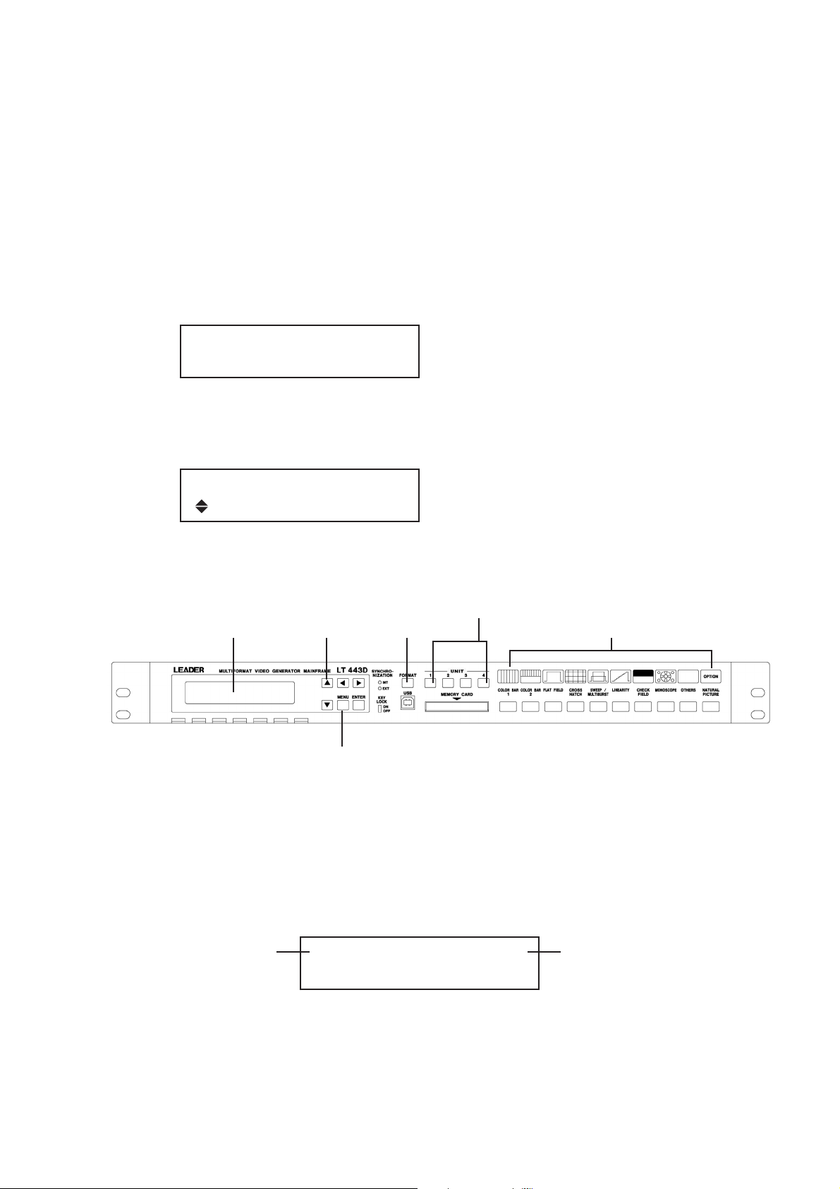
3. PANEL DESCRIPTION
q
er t
w
uio!0
y
Figure 3-1
3.1 Front Panel
Figure 3-1 shows the LT 443D front panel.
q LCD panel
Displays the information in 20 characters x 2 lines.
Generally displays the status (e.g., output format of the selected unit).
In the setting mode, the setting item of the selected unit is displayed.
w Menu keys
Sets the menu in the setting mode.
(These keys are also used in status display mode.)
e SYNCHRONIZATION indicators
The [EXT] lights when the instrument is synchronized to the external sync signal (e.g., black
burst, tri-level sync).
The [INT] lights when the internal sync is used.
r FORMAT key
Selects the signal format of the selected unit.
t UNIT keys
Select the unit when changing or confirming the setting item.
y Pattern keys
Select the pattern output from the selected unit.
These keys are common to all units.
When the unit without a pattern output capability (e.g., genlock unit) is selected, all pattern
LEDs go off. And pattern key could not use.
3-1
Page 22

u MEMORY CARD slot
To insert memory card to store the optional NATURAL PICTURE pattern.
Procure a compact flash memory card recommended by Leader Electronics Corp. Refer to
Section 2.3.4, “Memory Card Slot” for detail.
*Note: When formatting a CF card, use the FAT system; the LT 443D cannot recognize the
CF card formatted in FAT32 system.
To format the CF card of 32 MB or larger capacity on Windows XP, select FAT from
the default (FAT32 file system selected) for formatting.
Notes on using CF memory card:
• A “Vcc = 5 V” type memory card cannot be used.
• Insert the memory card until it in place. If the card cannot be inserted properly, check the
card for up side down. Do not insert the card forcibly. It may cause trouble.
• Do not remove the card while writing or recalling data.
• Do not turn power off while writing or recalling data.
i USB connector
Used for maintenance in the factory. This connector will be installed.
o KEY LOCK switch
Turns on and off the key lock mode.
!0 Ventilation hole
To prevent instrument damage due to overheating, do not block airflow through the ventilation
vents (i.e., air-intake vents on the rear panel and exhaust holes on the front panel).
3.2 Rear Panel
!1 !2 !3 !4 !5 !6 !7 !8
UNIT1 UNIT2 UNIT3 UNIT4
Figure 3-2
Figure 3-2 shows the LT 443D rear panel.
!1 UNIT 1 compartment
!2 UNIT 2 compartment
!3 UNIT 3 compartment
!4 UNIT 4 compartment
3-2
Page 23

!5 Cooling fan
Do not block air flow and ventilation holes.
!6 Grounding terminal
Connected to the chassis of this instrument.
!7 AC inlet
AC power inlet. Usable AC voltage range is 90 to 250 V, universal.
!8 ETHER connector
Used for 10 BASE-T/100 BASE-TX ethernet.
3-3
Page 24
4. USING THE MAINFRAME
4.1 Turning Power On
*Note: There is no power switch on the LT 443D; connecting the power cord immediately
supplies the power.
(1) Supplying the power initializes this instrument.
The following message is displayed until initialization is completed.
During initialization, incorrect signal is output and key operation is disabled.
LEADER LT443D
(Example: When the power is supplied.)
INITIALIZING •••
(2) After initialization is completed, the setting status (e.g., video format being output) is
displayed as shown below.
[STATUS] FORMAT TYPE
(Example of status display)
1080/59.94
Refer to Sections 4.2, 4.3, and 4.4 for front panel operations.
UNIT switch
LCD panel Up/Down key
qwr
FORMAT key
t
Pattern selection key
y
4.2 Selecting Unit
Pressing one of UNIT keys displays the UNIT number and its information on the LCD
panel.
This section describes the operating procedure in case of the HD-SDI unit is installed in
the UNIT 2 compartment.
Hierarchy level 1
If [STATUS] is displayed, pressing the [MENU] key can display the [SETTING].
w
MENU key
1. HD SETTING #2
▼ FORMAT SELECT
4-1
In case of the LT 443D-HD
unit is installed in the UNIT 2
compartment.
Page 25
4.3 Selecting Format
Press the FORMAT switch to select the signal format.
Pressing the [Up] or [Down] key in the LCD panel group can also select the signal format.
Hierarchy level 2
4.4 Selecting Pattern
Press the Pattern key to select the pattern.
Pressing the key lights the key LED and outputs the pattern.
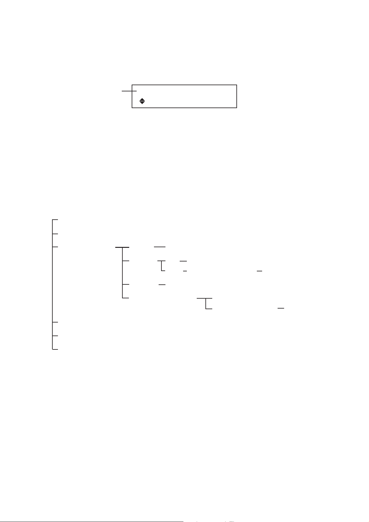
4.5 UTILITY Menu Structure
The UTILITY menu can be commonly used for each unit.
To enable this menu, turn four UNIT LEDs off, then press the [MENU] key.
4.5.1 UTILITY Menu Screen
LCD BACK LIGHT (HIGH, MID, LOW, OFF)
KEY LOCK SET (ON/OFF)
PRESET/RECALL MEDIA MEDIA INT/EXT (INT_MEM, EXT_CARD)
RECALL ALL RECALL No. 1 to No. 9
2. FORMAT SELECT
*1080i/59.94
UNIT RECALL No. 1 to No. 9 SLOT1 to 4 → SLOT1 to 4
PRESET PRESET No. 1 to No. 9
POWER ON RECALL
ETHERNET SET (IP: ***. *** . ***. ***)
DATE & TIME SET (20XX/XX/XX XX:XX:XX)
VERSION DISPLAY
4.5.2 LCD BACK LIGHT
The backlight brightness can be selected: HIGH, MIDDLE, LOW, or OFF.
4.5.3 KEY LOCK SET
The key lock function prevents a trouble from accidental key operation.
There are two key lock modes as follows:
All front panel keys are locked by using the [KEY LOCK SET] in setting mode.
The [FORMAT] key is only locked by pressing the KEY LOCK switch in the SYSTEM block
r on the front panel.
4.5.3.1 Key Lock Mode Set With Menu
P-ON RECALL ON/OFF
RECALL NUMBER INT_MEM 1 to 3
When the [KEY LOCK SET] is ON, keys related to the SYSTEM (including [FORMAT]
and [INT/EXT] keys) are disabled.
4-2
Page 26

4.5.3.2 Setting KEY LOCK ON
(1) Select the [KEY LOCK SET] by pressing the [Up] or [Down] key, then press the
[ENTER] key.
Hierarchy level 1
(2) The key lock mode is enabled. [KEY LOCK ON] is displayed for about one second,
then status mode is enabled.
When the key is pressed in key lock mode, the following message is displayed for
about one second.
4.5.3.3 Setting KEY LOCK OFF
(1) To cancel key lock mode, hold down the MENU key for at least two seconds.
[KEY LOCK OFF] is displayed for about one second.
1. UTILITY MENU
KEY LOCK SET
KEY LOCK ON
KEY LOCK !!
PUSH MENU KEY 2 sec
KEY LOCK OFF
*The [FORMAT] in the SYSTEM block are disabled during the KEY LOCK switch
o is set ON even when the key lock mode is canceled with the menu.
4.5.4 Using Front Panel KEY LOCK Switch
Setting the [KEY LOCK] slide switch on locks the [FORMAT] key operation.
If the [FORMAT] key is pressed when the [KEY LOCK] slide switch is set on, the LCD
displays the following messages:
KEY LOCK ON
TURN OFF KEY_LOCK_SW
When setting the KEY LOCK slide switch, use an insulated wedge-shaped screwdriver, for
example.
4-3
Page 27
4.5.5 PRESET / RECALL
You can store up to three presets of the panel key settings to in the internal memory
(INT_MEM) and up to nine presets to a Compact Flash card (EXT_CARD) *1, *2.
There are two methods to recall presets: One method in which the settings of all slots are
recalled at once (ALL mode) and another method in which the settings are recalled on
each slot individually (UNIT mode). *3
*1 The compact flash card is not included in the package. The memory card can be
shared with Option 70 (color still picture memory).
*2 The INT_MEM preset function is supported on firmware version 1.8 or later.
*3 The recall function per slot is supported on firmware version 2.1 or later.
*4 The POWER ON RECALL mode has been applied for firmware version 3.0 and later.
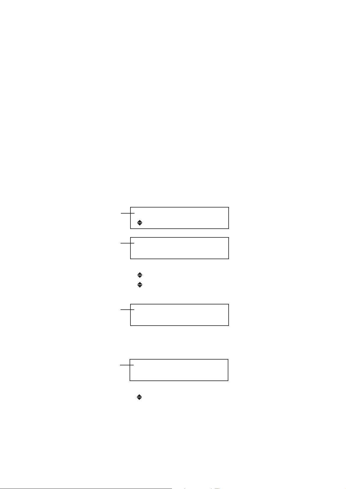
4.5.5.1 Selecting the Preset Storage Media
Set the medium for storing presets. You can select INT_MEM (internal memory) or
EXT_CARD (Compact Flash card).
Data stored in the INT_MEM (internal memory) can only be recalled in the POWER ON
RECALL mode.
Hierarchy level 1
Hierarchy level 2
Hierarchy level 3
4.5.5.2 Creating Presets
You can create three presets in INT_MEM and nine presets in EXT_MEM.
Hierarchy level 3
1. UTILITY MENU
PRESET/RECALL
2. PRESET/RECALL
▼ MEDIA
▼ MEDIA
RECALL
PRESET
▲POWER ON RECALL
3. MEDIA INT/EXT
■INT_MEM □ EXT_CARD
3. PRESET (INT_MEM)
▼PRESET No. 1 NO DATA
▼PRESET No. 1 NO DATA
PRESET No. 2
▲PRESET No. 3
The current information about the preset data is
displayed at the right edge of the second line.
NO DATA: No preset data is stored.
No display: Preset data is stored.
4-4
Page 28
Hierarchy level 3
3. PRESET (EXT_CARD)
▼PRESET No. 1 NO DATA
▼PRESET No. 1 NO DATA
PRESET No. 2
▲PRESET No. 8
PRESET No. 9
Hierarchy level 4
Hierarchy level 4
Hierarchy level 4
The following messages may appear in addition to the messages above.
Hierarchy level 3
Hierarchy level 4
4. PRESET No. 1
□OK ■ CANCEL
4. PRESET No.1
WORKING...
4. PRESET No.1
COMPLETE !
3. PRESET (EXT_CARD)
NO CARD !
4. WARNING !! OVER WR?
□OK ■ CANCEL
Writing
Writing complete
When the Compact Flash
card is not inserted
When a preset is already
stored
(overwrite confirmation)
4.5.5.3 Recalling Presets (ALL Mode)
In ALL mode, the settings of the units installed in the four slots can be recalled at once.
However, if the configuration of the units installed in slots 1 to 4 differs from that when the
preset was created, the settings cannot be recalled. If this happens, you may be able to
recall using UNIT mode.
Hierarchy level 3
The current information about the preset data is
displayed at the right edge of the second line.
NO DATA: No preset data is stored.
No display: Preset data is stored.
3. RECALL (INT_MEM)
▼RECALL No. 1 NO DATA
▼RECALL No. 1 NO DATA
RECALL No. 2
▲RECALL No. 3
4-5
Page 29
Hierarchy level 3
3. RECALL (EXT_CARD)
▼RECALL No. 1
▼RECALL No. 1
RECALL No. 2
▲RECALL No. 8
RECALL No. 9
Hierarchy level 4
Hierarchy level 5
Hierarchy level 5
Hierarchy level 5
The following messages may appear in addition to the messages above.
Hierarchy level 5
4. RECALL (EXT_No. 1)
■ALL □ UNIT
5. RECALL (EXT_No. 1)
□OK ■ CANCEL
5. RECALL (EXT_No. 1)
WORKING...
5. RECALL (EXT_No. 1)
COMPLETE !
5. RECALL (EXT_No. 1)
NO RECALL DATA !
Select the ALL.
Loading
Loading complete
When there is no data
Hierarchy level 5
Hierarchy level 5
4.5.5.4 Recalling Presets (UNIT Mode)
In UNIT mode, the settings of a particular slot can be recalled from the preset data of all
the settings of the units installed in the four slots.
Hierarchy level 4
5. RECALL (EXT_No. 1)
MISMATCH UNIT !
5. RECALL (EXT_No. 1)
NO CARD !
4. RECALL (EXT_No. 1)
□ALL ■ UNIT
When the data was
created using a different
unit configuration
When the Compact Flash
card is not inserted
Select UNIT.
4-6
Page 30
Hierarchy level 5
q Preset data information (unit configuration when the preset was created)
w The LT 443D slot number for which the settings are to be recalled
e Unit type matching
OK: The unit type for q and w match or are compatible, and the settings can be
recalled.
NG: The unit type for q and w do not match or are not compatible, and the settings
cannot be recalled.
Select the unit within the preset data corresponding to q using the [ ▲ ] or [ ▼] key.
5. RECALL (EXT_No. 1)
▼SLOT1・GLA →SLOT1 OK
▼SLOT1・GLA→ SLOT1 OK
SLOT2・HD → SLOT1 NG
SLOT3・BL → SLOT3 OK
▲SLOT4・SD → SLOT4 OK
q w e
Hierarchy level 5
Use the [] or [] key to move the cursor to the w position and select the LT 443D unit
whose settings are to be recalled. The settings can be recalled using a combination in
which OK is displayed in e.
Hierarchy level 6
Hierarchy level 6
Hierarchy level 6
The following messages may appear in addition to the messages above.
Hierarchy level 5
5. RECALL (EXT_No. 1)
SLOT1・GLA →▼SLOT1 OK
6. EXT_No. 1・GLA (1 →1)
□OK ■ CANCEL
6. EXT_No. 1・GLA (1 →1)
WORKING...
6. EXT_No. 1・GLA (1 →1)
COMPLETE !
5. RECALL (EXT_No. 1)
NO RECALL DATA !
Loading
Loading complete
When there is no data
Hierarchy level 6
Hierarchy level 5
6. EXT_No. 1・GLA (1 →2)
MISMATCH UNIT !
5. RECALL (EXT_ −−)
NO CARD !
4-7
When the unit type does
not match (a combination
consisting of NG displays)
When the Compact Flash
card is not inserted
Page 31

4.5.5.5 POWER ON RECALL
The following functions can be selected in the POWER ON RECALL mode.
To initialize each unit based on the last memory setting information (i.e., information
immediately before turning power off) when power is turned on.
To initialize each unit by recalling the setting information from preset data stored in the
internal memory (INT_MEM).
Hierarchy level 3
Hierarchy level 4
Select POWER ON RECALL ON/OFF by pressing the or key, then press the ENTER
key.
When OFF is selected, each unit is initialized based on the last memory setting
information.
When ON is selected, each unit is initialized by recalling the setting information of the
RECALL NUMBER listed below from preset data stored in the INT_MEM (internal
memory).
When there is no setting information at the specified number, each unit is initialized
based on the last memory setting information.
3. POWER ON RECALL
▼ P-ON RECALL ON/OFF
▼ P-ON RECALL ON/OFF
▲RECALL NUMBER
4. P-ON RECALL ON/OFF
□OK ■ OFF
Hierarchy level 4
Select the number by pressing the ▲ (Up) or ▼(Down) key. The item indicated as NO
DATA cannot newly be specified by attaching “ * ” (asterisk).
4. RECALL NUMBER
▼* INT_MEM 1
▼*INT_MEM 1
INT_MEM 2 NO DATA
▲INT_MEM 3 NO DATA
4-8
Page 32

4.5.6 ETHERNET SET
The ethernet capability can remotely control and monitor genlock status.
Hierarchy level 2
The current setting value is displayed.
The underline cursor can be moved by pressing the [Left] or [Right] key.
The cursored number can be changed by pressing the [Up] or [Down] key.
Pressing the [ENTER] key enters data.
*”ETHER” is set to IP address when power is turned on.
4.5.6.1 Remote Control via ETHER Port
This section describes the remote control procedure using the “TELNET” software.
2. ETHERNET SET
IP: 192. 168. 20. 63
IP: 192. 168. 20. 63
■ OK □ CANCEL
Select “Run” from the Start menu.
To run application software, enter “TELNET” in the
“Open” column, then click “OK.”
Click “Remote System” in the “Connect” menu.
4-9
Page 33

Enter LT 443D IP address in the “Host Name,”
select “telnet” for “Port,” select “vt100” for
“Term Type,” then click “Connect.”
When “login:” is displayed, enter “LT443D” in uppercase letters,
then press the “Enter” key. A password can now be entered.
Enter “LT443D” in uppercase letters, then press the “Enter” key.
The command prompt “LT443D>” is displayed. A command can
now be entered.
LT443D>MO?
MO:LT443D-70,GLA,--,BL,SD
LT443D>
The command can be entered on this screen; data can be
sent to the LT 443D.
Command “MO?” (to query the plug-in unit inserted) is
entered, for example, “MO: LT443D-70, GLA, - -, BL, SD” is
replied.
When the prompt “LT443D>” is displayed, a new command
can be entered.
4.5.6.2 Exiting Remote Control Mode
To exit “TELNET,” click “Exit” in the “Connect” menu.
4-10
Page 34

4.5.6.3 Remote Control Command
Operating precautions for remote controlling via the ETHER port
Do not enter multistatement command.
Enter a space (0X20) between command and data.
Enter a comma (0X2C) between data.
In remote control mode, LED on the main frame is undefined, either on or off. Use the
query command to confirm the settings in this case.
(1) MAINFRAME
Query of Model Number MO?
MO: LT443D-70, GLA, HD, BL, SD With Option 70
MO: LT443D, - -, HD, BL, - - Without Option 70
The unit type is sequentially displayed from the UNIT compartment 1.
”- -” indicates “without option.”
Confirming firmware version VR? VR: LT443D-70 V1.0
(2) HD Unit (Installed in UNIT 2)
• Getting format FM2? FM2: 11
0 = 1035i/60 7 = 1080p/25 14 = 720p/50
1 = 1035i/59.94 8 = 1080p/24 15 = 720p/30
2 = 1080i/60 9 = 1080p/23.98 16 = 720p/29.97
3 = 1080i/59.94 10 = 1080PsF/24 17 = 720p/25
4 = 1080i/50 11 = 1080PsF/23.98 18 = 720p/24
5 = 1080p/30 12 = 720p/60 19 = 720p/23.98
6 = 1080p/29.97 13 = 720p/59.94
• Selecting pattern PA2 X
0 = COLOR BAR 75 % 11 = RAMP
1 = COLOR BAR 100 % 12 = SHALLOW RAMP
2 = MULTIFORMAT COLOR BAR 1 13 = 10 STEP
3 = (unused) 14 = CHECK FIELD
4 = (unused) 15 = MONOSCOPE (NORMAL)
5 = FLAT FIELD 100 % 16 = MONOSCOPE (INVERT)
6 = FLAT FIELD 50 % 17 = BOWTIE 100 %
7 = FLAT FIELD 0 % 18 = PULSE & BAR
8 = CROSS & DOT 19 = RED RASTER
9 = LINE SWEEP 100 % 20 = (unused)
10 = MULTIBURST 100 % 21 = (unused)
4-11
Page 35

• Getting pattern PA2? PA2: 0
0 = COLOR BAR 75 % 11 = RAMP
1 = COLOR BAR 100 % 12 = SHALLOW RAMP
2 = MULTIFORMAT COLOR BAR 1 13 = 10 STEP
3 = MULTIFORMAT COLOR BAR 2 14 = CHECK FIELD
4 = MULTIFORMAT COLOR BAR 3 15 = MONOSCOPE (NORMAL)
5 = FLAT FIELD 100 % 16 = MONOSCOPE (INVERT)
6 = FLAT FIELD 50 % 17 = BOWTIE 100 %
7 = FLAT FIELD 0 % 18 = PULSE & BAR
8 = CROSS & DOT 19 = RED RASTER
9 = LINE SWEEP 100 % 20 = NATURAL PICTURE 1 (w/Option 70)
10 = MULTIBURST 100 % 21 = NATURAL PICTURE 2 (w/Option 70)
• Setting ID ON/OFF ID2 X
0 = ID OFF 1 = ID ON
• Getting ID ON/OFF ID2? ID2: 0
0 = ID OFF 1 = ID ON
4-12
Page 36

(3) SD Unit (Installed in UNIT 4)
• Getting format FM4? FM4: 0
0 = 525i/59.94
1 = 625i/50
• Selecting pattern PA4 X
[ 525i/59.94 ] [ 625i/50 ]
0 = COLOR BAR 100 % 0 = COLOR BAR 100 %
1 = COLOR BAR 75 % 1 = EBU COLOR
2 = SMPTE 2 = BBC COLOR
3 = RAMP & COLOR BAR 3 = RAMP & COLOR BAR
4 = FLAT FIELD 100 % *4 to 28: Same as the “525i/59.94.”
5 = FLAT FIELD 50 %
6 = FLAT FIELD 0 %
7 = FIELD ID
8 = CROSSHATCH
9 = LINE SWEEP 100 %
10 = LINE SWEEP 60 %
11 = MULTIBURST 100 %
12 = MULTIBURST 60 %
13 = OVER SIZE RAMP
14 = DIGITAL LIMIT RAMP
15 = SHALLOW RAMP
16 = 10 STEP
17 = CHECK FIELD
18 = MONOSCOPE (NORMAL)
19 = MONOSCOPE (INVERT)
20 = BOWTIE 100 %
21 = PULSE & BAR
22 = RED RASTER
23 = MULTIPULSE
24 = (unused)
25 = (unused)
26 = (unused)
27 = (unused)
28 = (unused)
4-13
Page 37

• Getting pattern PA4? PA4: 0
[ 525i/59.94 ] [ 625i/50 ]
0 = COLOR BAR 100 % 0 = COLOR BAR 100 %
1 = COLOR BAR 75 % 1 = EBU COLOR
2 = SMPTE 2 = BBC COLOR
3 = RAMP & COLOR BAR 3 = RAMP & COLOR BAR
4 = FLAT FIELD 100 % *4 to 28: Same as the “525i/59.94.”
5 = FLAT FIELD 50 %
6 = FLAT FIELD 0 %
7 = FIELD ID
8 = CROSSHATCH
9 = LINE SWEEP 100 %
10 = LINE SWEEP 60 %
11 = MULTIBURST 100 %
12 = MULTIBURST 60 %
13 = OVER SIZE RAMP
14 = DIGITAL LIMIT RAMP
15 = SHALLOW RAMP
16 = 10 STEP
17 = CHECK FIELD
18 = MONOSCOPE (NORMAL)
19 = MONOSCOPE (INVERT)
20 = BOWTIE 100 %
21 = PULSE & BAR
22 = RED RASTER
23 = MULTIPULSE
24 = NATURAL PICTURE 1 (w/Option 70)
25 = NATURAL PICTURE 2 (w/Option 70)
26 = NATURAL PICTURE 3 (w/Option 70)
27 = NATURAL PICTURE 4 (w/Option 70)
28 = NATURAL PICTURE 5 (w/Option 70)
• Setting ID ON/OFF ID4 X
0 = ID OFF 1 = ID ON
• Getting ID ON/OFF ID4? ID4: 0
0 = ID OFF 1 = ID ON
4-14
Page 38

(4) BL Unit (Installed in UNIT 3)
• Getting BLACK 1, 2 format FM31? FM31: 1
Getting BLACK 3, 4 format FM32? FM32: 0
Getting BLACK 5, 6 format FM33? FM33: 3
0 = 1035i/60 17 = 720p/25
1 = 1035i/59.94 18 = 720p/24
2 = 1080i/60 19 = 720p/23.98
3 = 1080i/59.94 20 = NTSC BB
4 = 1080i/50 21 = NTSC BB+Ref
5 = 1080p/30 22 = NTSC BB+ID
6 = 1080p/29.97 23 = NTSC BB+Ref+ID
7 = 1080p/25 24 = NTSC BB+Setup
8 = 1080p/24 25 = NTSC BB+S+Ref
9 = 1080p/23.98 26 = NTSC BB+S+ID
10 = 1080PsF/24 27 = NTSC BB+S+R+ID
11 = 1080PsF/23.98 28 = 525i/59.94
12 = 720p/60 29 = 525p/59.94
13 = 720p/59.94 30 = PAL BB
14 = 720p/50 31 = PAL BB+Ref
15 = 720p/30 32 = 625i/50
16 = 720p/29.97 33 = 625p/50
(5) GLA Unit (Installed in UNIT 1)
• Getting GENLOCK operation status GE1? GE1: 0
0 = INTERNAL or FLYWHEEL 1 = EXTERNAL
• Getting BLACK 1 format FM11? FM11: 1
Getting BLACK 2 format FM12? FM12: 0
Getting BLACK 3 format FM13? FM13: 3
Parameters are same as the “Getting BLACK 1, 2 format” of BL.
4-15
Page 39

(6) List of Query Command
Command Parameter Function
• MAINFRAME
MO?
VR?
• HD (Installed in UNIT 2, for example)
FM2?
PA2?
ID2?
• SD (Installed in UNIT 4, for example)
FM4?
PA4?
None
None
UNIT No. (1-4)
UNIT No. (1-4)
UNIT No. (1-4)
UNIT No. (1-4)
UNIT No. (1-4)
Queries unit inserted
Queries version
Confirming format
Getting pattern
Getting ID ON/OFF
Confirming format
Getting pattern
Reply Example
MO: LT443D-70, GL, HD,
BL, SD
MO: LT443D, - -, HD, BL, - -
VR: LT443D-70 V1.0
FM2: 0
FM2: 13
PA2: 0
PA2: 21
ID2: 0
ID2: 1
FM4: 0
FM4: 1
PA4: 0
PA4: 28
ID4?
• BL (Installed in UNIT 3, for example)
FM31?
FM32?
FM33?
• GLA (Installed in UNIT 1, dedicated)
GE1?
FM11?
FM12?
FM13?
UNIT No. (1-4)
UNIT No. (1-4)
Output No. (1)
UNIT No. (1-4)
Output No. (2)
UNIT No. (1-4)
Output No. (3)
UNIT No. (1)
UNIT No. (1)
Output No. (1)
UNIT No. (1)
Output No. (2)
UNIT No. (1)
Output No. (3)
Getting ID ON/OFF
Confirming BLACK
1, 2 format
Confirming BLACK
3, 4 format
Confirming BLACK
5, 6 format
Getting GENLOCK
operation status
Confirming BLACK 1
format
Confirming BLACK 2
format
Confirming BLACK 3
format
ID4: 0
ID4: 1
FM31: 0
FM31: 33
FM32: 0
FM32: 33
FM33: 0
FM33: 33
GE1: 0
GE1: 1
FM11: 0
FM11: 33
FM12: 0
FM12: 33
FM13: 0
FM13: 33
4-16
Page 40

(7) List of Setting Command
Command Parameter Function
• HD (Installed in UNIT 2, for example)
PA2 X
ID2 X
• SD (Installed in UNIT 4, for example)
PA4 X
ID4 X
*There is no setting item for the MAINFRAME, BL unit, and GLA unit.
4.5.7 VERSION DISPLAY
The software version used for this instrument can be confirmed.
UNIT No. (1-4)
Pattern No.
UNIT No. (1-4)
Setting ID
UNIT No. (1-4)
Pattern No
UNIT No. (1-4)
Setting ID
Selecting pattern
Setting ID ON/OFF
Selecting pattern
Setting ID ON/OFF
Reply Example
PA2: 0
PA2: 19
ID2: 0
ID2: 1
PA4: 0
PA4: 23
ID4: 0
ID4: 1
2. VERSION DISPLAY
LT 443D Ver 3.3
4-17
Page 41

4.6 Main Menu Structure
STATUS display mode display
SETTING menu mode display
MENU key
Executing status display
Executing setting menu
MENU or FORMAT key
MENU or EXIT key
ENTER key
MENU key
4.6.1 Two Modes Selectable With MENU Key
When one of four UNIT LEDs lights, pressing the [MENU] key on the LT 443D front panel
can select the STATUS display mode or SETTING menu mode.
4.6.2 STATUS Display Mode
This mode displays the current setting conditions of the LT 443D mainframe.
The principal setting conditions of the selected unit (e.g., UNIT 2) is displayed as follows.
The status display mode is only used for checking the status; cannot be used for settings.
Display example
[STATUS] FORMAT TYPE
1080i/59.94
(1) Status Display Structure
The hierarchical structure for each unit is shown below:
q GENLOCK STATUS
GENLOCK STATUS: INT/EXT xxx *xxx The sign displays the locked format.
GENLOCK MODE: INTERNAL/AUTO (GO INTERNAL)/MANUAL (GO INT)/
AUTO (FLYWHEEL)/MANUAL (FLYWHEEL)
FORMAT TYPE BLK 1
FORMAT TYPE BLK 2
FORMAT TYPE BLK 3
4-18
Page 42

w ANALOG BLACK STATUS
t DA STATUS
FORMAT TYPE BLK 1, 2
FORMAT TYPE BLK 2, 4
FORMAT TYPE BLK 3, 6
e HD-SDI STATUS
FORMAT TYPE
V-PHASE (HD)
H-PHASE (HD)
V-PHASE (HDB)
H-PHASE (HDB)
EMB. AUDIO (HD)
EMB. AUDIO (HDB)
Y, Cb, Cr
ID CHARACTER
PATTERN SCROLL
PATTERN CHANGE
*Items with “(HDB)” is only applicable
to HDB.
CH1/CH2 ON/OFF
CH3/CH4 ON/OFF
CH5/CH6 ON/OFF
CH7/CH8 ON/OFF
y AA STATUS
CH1 ON/OFF, CH2 ON/OFF
u CS STATUS
FORMAT TYPE
CS F-PHASE
CS V-PHASE
CS H-PHASE
Y, C ON/OFF
APL MODE
ID CHARACTER
PATTERN SCROLL
PATTERN CHANGE
r SD-SDI STATUS
FORMAT TYPE
V-PHASE (SD)
H-PHASE (SD)
V-PHASE (SDB)
H-PHASE (SDB)
EMB. AUDIO (SD)
EMB. AUDIO (SDB)
Y, Cb, Cr
ID CHARACTER
PATTERN SCROLL
PATTERN CHANGE
*Items with “(SDB)” is only applicable
to SDB.
BLACK1 F-PHASE
BLACK1 V-PHASE
BLACK1 H-PHASE
BLACK2 F-PHASE
BLACK2 V-PHASE
BLACK2 H-PHASE
V. DRIVE V-PHASE
H. DRIVE H-PHASE
4.6.3 SETTING Menu Mode
This mode is described in the instruction manual of each unit.
4-19
Page 43

5. NOTES ON RACK MOUNTING
A size of this instrument conforms to 1U standards. Use the Rack Support supplied as standard
accessory. Also procure L-angles, shelves, and slide rails. Secure them to prevent damaging the
instrument.
Contact your local leader agent for more information.
Rack support
M3x10
(3mm in dia.)
screws
M4x10
(4mm in dia.)
screws
Slide rail
(inner member)
Slide rail
(outer member)
Fixed to the rack
Figure 5-1 Mounting slide rail
*Slide rail (outer member) mount method depends on types of racks. Read the rack instruction
manual for mounting.
5-1
Page 44
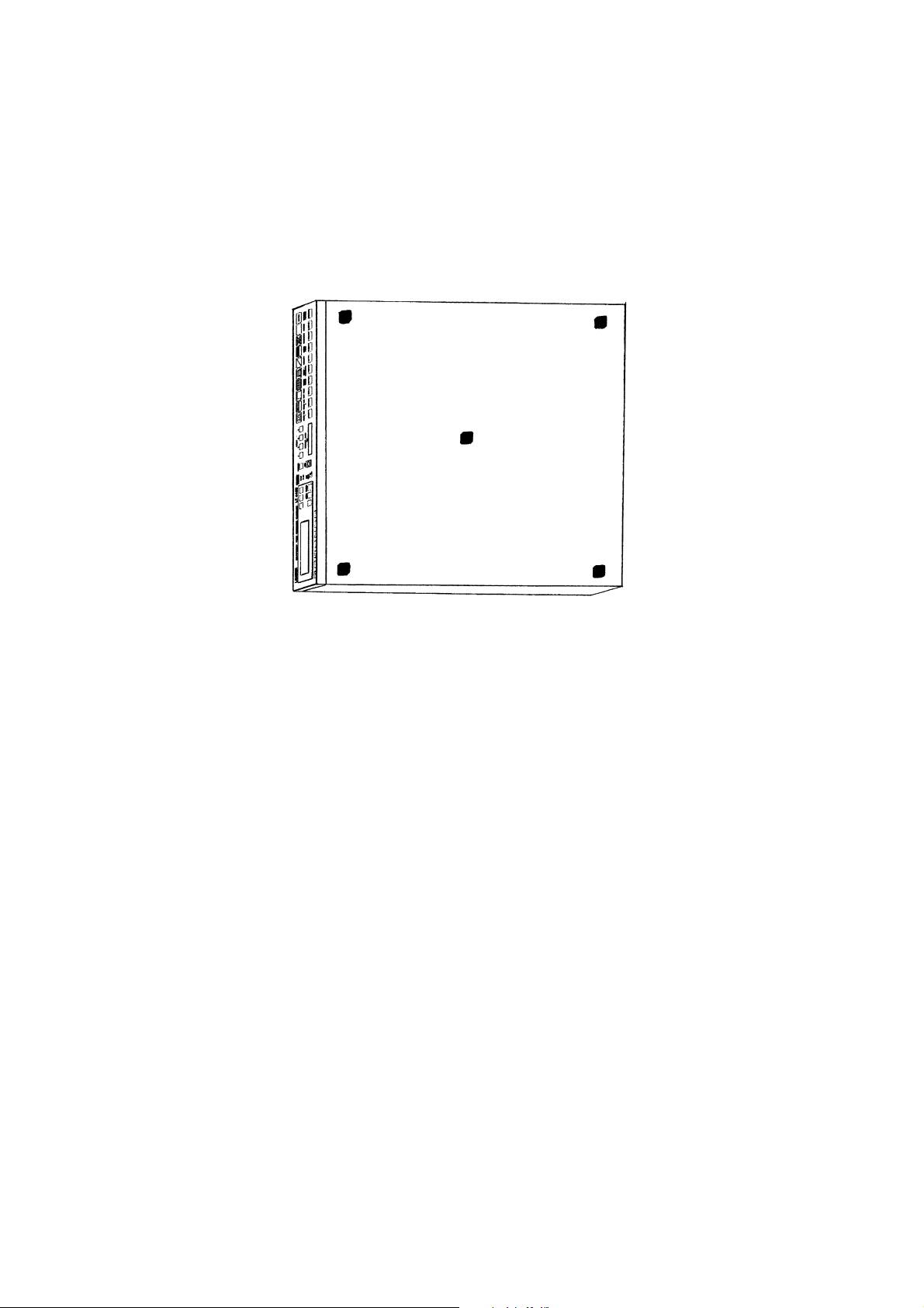
6. ABOUT RUBBER FEET
There are no rubber feet on the bottom of this instrument for rack-mounting purposes.
When using the instrument outside the rack or stack instruments on top of each other, attach five
rubber feet (supplied as standard accessory) as shown in Figure below to prevent the instrument
from scratching or falling.
Peel the seals before attaching the rubber feet.
LT 443D bottom
6-1
Page 45

7. DATA BACKUP
This instrument retains the menu setting contents and panel settings even when the power is
turned off.
• Backup battery
Manganese-Lithium primary battery
• Backup period
Data is backed up for about five years.
* Backup period depends on storage environment, operating conditions, etc.
7-1
Page 46

8. DEFAULT SETTINGS
8.1 Default Settings for All Data [MENU] + [FORMAT]
This section described the setting procedure to default all setting data (except DATE &
TIME).
*Caution: When the default setting is made, such data as backup and preset return to the
default value.
Procedure
1 Disconnect the power cord from the main unit for [POWER: OFF] state.
2 Hold down the [MENU] and [FORMAT] keys on the front panel simultaneously, then
insert the power cord to the main unit for [POWER: ON] state; do not release the keys,
here.
3 When [INITIALIZING...] is displayed on the front panel, release the [MENU] and
[FORMAT] keys.
4 When default setting is completed, [ALL DEFAULT SET COMPLETE!] is displayed on
the front panel LCD. A display check and ENTER key is pushed.
5 The default setting is now completed.
8.2 Default Settings for Selected Data [MENU] + [ENTER]
This section described the setting procedure to default basic data except the followings:
Preset data [INT_MEM PRESET No. 1 to 3]
[IP address] data
[DATE & TIME] data
*This function can be applied from the firmware version 1.8.
Procedure
1 Disconnect the power cord from the main unit for [POWER: OFF] state.
2 Hold down the [MENU] and [ENTER] keys on the front panel simultaneously, then
insert the power cord to the main unit for [POWER: ON] state; do not release the keys,
here.
3 When [INITIALIZING...] is displayed on the front panel, release the [MENU] and
[ENTER] keys.
4 When default setting is completed, [DEFAULT SET COMPLETE!] is displayed on the
front panel LCD. A display check and ENTER key is pushed.
5 The default setting is now completed.
8-1
Page 47
9. MAINTENANCE
9
The LT 443D is designed to operate stably under normal handling. If you have questions
regarding calibration and service, contact your local Leader agent.
9.1 Preventing Power Cord Disconnection
To prevent power cord disconnection from the AC inlet, the Cover/Inlet stopper is supplied
with the instrument. Refer to the procedure below.
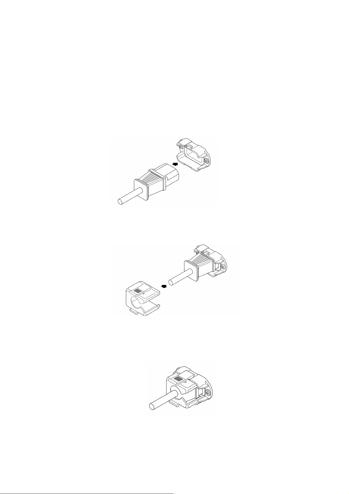
9.1.1 Connecting the Power Cord
① Insert the power cord connector into the AC inlet.
Base
Connector
② Place the Cover/Inlet stopper on top of the connector as shown below.
Cover/Inlet stopper
③ Press the cover until it clicks into place.
④ Confirm that the Cover/Inlet stopper is locked to the base.
-1
Page 48

9.1.2 Disconnecting the Power Cord
9
① Press the levers on the Cover/Inlet stopper with your fingers to release the lock.
② Remove the Cover/Inlet stopper from the base.
Cover/Inlet stopper (side view)
Cover/Inlet stopper
③ Disconnect the power cord connector from the AC inlet.
Base
Connector
-2
Page 49

UNIT INSTALLATION / REPLACEMENT
INSTRUCTION MANUAL
NOTE:
This instruction manual describes the procedures necessary for installing/replacing
various LT 443D units. Perform the work after checking the information and precautions
of the relative items in this manual.
LEADER ELECTRONICS CORP.
Page 50

TABLE OF CONTENTS
1. Introduction ............................................................................................................................ I-1
2. Scope of Warranty ................................................................................................................. I-1
3. Equipment and Tools Necessary for Performing the Work .................................................... I-1
4. Work Procedure ..................................................................................................................... I-2
4.1 Firmware Upgrade ........................................................................................................ I-2
4.2 Slot Selection ................................................................................................................ I-4
4.3 Unit Installation .............................................................................................................. I-5
4.4 System Initialization ...................................................................................................... I-7
4.5 About the Operation Check ........................................................................................... I-7
5. Operation Check .................................................................................................................... I-8
5.1 Operation Check of the LT 443D-GLA Genlock Unit ..................................................... I-8
5.2 Operation Check of the LT 443D-HD -HDB HD-SDI Unit ............................................ I-10
5.3 Operation Check of the LT 443D-BL Analog Black Unit .............................................. I-11
5.4 Operation Check of the LT 443D-SD -SDB SD-SDI Unit ............................................ I-12
5.5 Operation Check of the LT 443D-DA Digital Audio Unit .............................................. I-13
5.6 Operation Check of the LT 443D-AA Analog Audio Unit.............................................. I-14
5.7 Operation Check of the LT 443D-CS Analog Composite Unit ..................................... I-15
Page 51

1. Introduction
This instruction manual describes the procedures necessary for installing/replacing various LT
443D units.
Perform the work after checking the information and precautions of the relative items in this
manual.
2. Scope of Warranty
Install/Replace units or upgrade the firmware at the user’s own responsibility. If the product
malfunctions due to the user’s inadequate handling or a failure in the upgrading of the firmware,
repairs will be provided for a fee even if it is within the warranty period.
3. Equipment and Tools Necessary for Performing the Work
The table below shows the equipment and tools necessary for installing/replacing units and
upgrading the firmware. Additional measurement instruments are necessary if you are going to
check the operation of each unit. For details, see the operation check procedure of the
respective unit in chapter 5, “Operation Check.”
List of Equipment and Tools Necessary for Performing the Work
No.
1
2
3
Name
Screwdrivers for TORX
screws
Compact Flash card
(CF card)
Wrist strap
Note
For M3 x 6 mm binding screws with Hexalobular
socket head cap
CF card tested for compatibility by LEADER (made by
SanDisk Corporation)
For preset backup: 1 card
For firmware updating: 1 card
As a measure for countering electrostatic discharge
I-1
Page 52

4. Work Procedure
The work flow is shown below.
4.1 Firmware upgrade
4.2 Slot selection
4.3 Unit installation
4.4 System initialization
4.5 Unit operation check
4.1 Firmware Upgrade
If you are installing/replacing units, you may need to upgrade the main frame firmware. In
addition, the main frame settings are initialized during the installation or replacement of
units. Therefore, you should back up the main frame settings as necessary.
*For information on obtaining the newest version of the firmware, contact your local
Leader agent.
1) Checking the Firmware Version
a) Turn off the front panel [UNIT] key LED on the main frame.
b) From “1. UTILITY MENU” that is shown on the front panel LCD, select “VERSION
DISPLAY.”
c) Check the firmware version that is shown. If the current main frame firmware version
is older (the version number is smaller) than the newest firmware version, you must
upgrade the firmware.
Note: Firmware upgrading
• Even if you are installing the same type of unit that is installed, if the firmware
version is older (the version number is smaller) than the newest version, upgrade
the firmware.
• Please note that if the unit is a special order model, functions specific to the model may
no longer work if you upgrade the firmware using the firmware of the standard model.
• If the firmware version is less than 1.6, it may be necessary to upgrade data other
than the firmware. Please consult your local Leader agent in this case.
2) Backing Up Various Settings
When you install/replace a unit or upgrade the firmware, settings must be initialized.
When initialization is performed, various unit settings (excluding the LT 443D time
setting) and internal presets are reset to their factory default. If you need to retain the
settings, backup the following items.
• Internal presets (No.1 to 3: 3 items)
• Last memory (main frame settings that exist immediately before the power is turned
OFF: 1 item)
• Ethernet (IP Address, Subnet Mask, and Gateway: 3 items)
I-2
Page 53

Note: Backing up the settings
• Internal presets and last memory can be backed up on a Compact Flash card (CF
card). Ethernet settings are not included in the preset. Please retain the settings
such as by taking a memo.
• For the procedure of storing presets to the CF card, see the item of “MAINFRAME”
in this manual.
• For backing up the data, use a CF card that is separate from the card used to
upgrade the firmware.
3) Upgrading the Firmware
a) Remove all cables that are connected to the LT 443D units.
b) Turn on the power to the main frame.
c) Insert the CF card for upgrading the firmware into the MEMORY CARD slot on the
front panel of the LT 443D main frame.
d) When the front panel LCD shows a screen illustrated in Figure 4-1-1, press the
[ENTER] key. The firmware upgrading starts.
CF OPERATION
▼CF (Ver X.X) → 443D
Figure 4-1-1
e) While the firmware is being upgraded, the LCD shows a screen illustrated in Figure
4-1-2, and the INT and EXT SYNCHRONIZATION LEDs illuminate alternately.
PROG. SYSTEM FLASH
Write: -------------- ------
Figure 4-1-2
f) When the firmware upgrading is finished, the main frame automatically restarts.
Then, the screen shown in Figure 4-1-1 appears again. Remove the CF card.
g) Check that the firmware has been upgraded by carrying out the procedure described
in 1), “Checking the Firmware Version.”
Note: Firmware upgrading
• When upgrading the firmware, remove all cables except the power cord. Be
especially certain that nothing is connected to the genlock connector. Upgrading the
firmware while the genlock function is in operation may hinder proper firmware
upgrading. In addition, the signal condition of the output connectors of each unit
may be abnormal while the firmware upgrade is in progress.
• To avoid problems such those related to compatibility, use CF cards (made by
SanDisk Corporation) that have been tested by Leader for backing up data.
• Do not operate the keys while the firmware upgrade is in progress.
• If the power is cut off while the firmware upgrade is in progress, the unit may no longer
be able to startup. Never cut off the power while the firmware upgrade is in progress.
I-3
Page 54

4.2 Slot Selection
Table 4-2-1 shows the possible combinations of units. Select the slots to be used
according to Table 4-2-1.
q
Unit Model
LT443D-GLA
LT443D-GL
LT443D-HD/HDB
LT443D-BL
LT443D-SD/SDB
LT443D-DA
LT443D-AA
LT443D-CS
Yes: Installable, No: Not installable
wer
Figure 4-2-1 Main Frame Rear Panel
Table 4-2-1
Slot
q
Slot 1
Yes
Yes
Yes
Yes
Yes
Yes
Yes
Yes
w
Slot 2
No
No
Yes
Yes
Yes
Yes
Yes
Yes
e
Slot 3
No
No
Yes
Yes
Yes
Yes
Yes
Yes
r
Slot 4
No
No
Yes
Yes
Yes
Yes
Yes
Yes
*Note: The firmware version 3.0 and later is used for the LT 443D-GLA.
The unit cannot be confirmed by an old version.
The firmware version can be confirmed on the VERSION DISPLAY in MAINFRAME
menu.
I-4
Page 55

4.3 Unit Installation
Install the unit into the slot.
a) Turn off the power to the main frame.
b) Remove the screws that are fixing the blank panel in place (Figure 4-3-1 (a)).
If a unit is already installed, remove the screws that are fixing the unit in place, place
75 Ω terminators on the unit’s BNC connectors, and pull the unit out. If the unit has
Canon connectors, attach Canon connector plugs, and then pull the unit out.
c) Check that there are no problems in the connector pins inside the slot (Figure 4-3-1 (b)).
d) Insert the unit’s board into the rail grooves (Figure 4-3-1 (c)).
e) Slide the unit in until the unit no longer moves inward (Figure 4-3-1 (d)).
f) Press the unit further into the slot to connect the main frame and unit connectors.
Check that the top and bottom steel plates of the main frame are closely aligned with
the units panel (Figure 4-3-1 (e)).
g) Fix the unit in place using screws (binding screws with Hexalobular socket head cap
M3 x 6 mm). (Figure 4-3-1 (f))
Note: Handling of the unit and main frame
Each unit uses parts that are susceptible to damage from electrostatic discharge.
Damage can also result when mechanical stress is applied to the parts on the board.
Be sure to observe the following points.
• If you are carrying the unit, use dedicated packing material that has measures taken
against static electricity.
• If you are installing the unit, use a wrist wrap to prevent damage caused by static
electricity built up in your body. If a wrist wrap is not available, discharge the statistic
electricity on your body by using metal parts of a rack or something similar.
• While installing or replacing a unit, do not bring objects that may discharge static
electricity.
• When holding the unit in your hand, hold the chassis. Do not touch the parts or
connector pins on the board.
• Be sure to turn off the power to the main frame when installing or replacing a unit.
• Insert the unit in the appropriate slot according to Table 4-2-1.
• Before installing the unit, check that there are no problems in the slot connector pins
(such as a bent or broken pin).
• Be sure not to lose the unit attachment screws.
• Be sure to attach blank panels that come with the LT 443D main frame to unused
slots.
• The number of times that the connector connecting the main frame and the unit can
be attached and removed is 500. Avoid using the unit in a way that requires it to be
attached and removed frequently as it may cause a malfunction.
I-5
Page 56
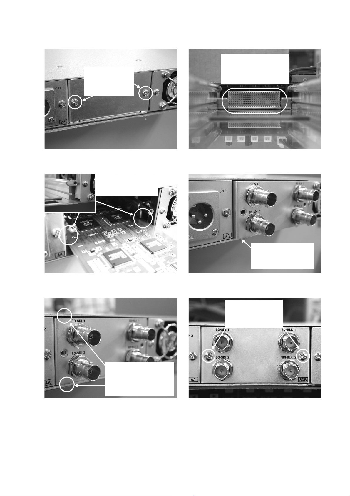
Remove the M3 x 6
binding screws with
Hexalobular socket
head cap.
(a) (b)
Insert the board in the
grooves of the left and
right rails.
Check that there are no
problems in the slot
connector pins (such as a
bent or broken pin).
(c) (d)
Fasten M3 x 6 mm
binding screws with
Hexalobular socket
head cap.
Press the unit firmly and
check that the top and
bottom steel plates of the
main frame are closely
aligned with the units panel.
(e) (f)
Slide the unit in lightly
until the unit no longer
moves inward.
Figure 4-3-1
I-6
Page 57

4.4 System Initialization
Initialize the main frame settings and check that the system starts up normally. When you
initialize the main frame settings, the settings are reset to their factory default.
Then, as necessary, restore the settings that you backed up.
1) Initialization Procedure
a) While holding down the [MENU] key and [FORMAT] key simultaneously, turn on the
power.
b) When the LCD shows a screen illustrated in Figure 4-4-1, release the keys.
c) If the initialization is successful and the system starts up normally, a screen illustrated
in Figure 4-4-2 appears. Check the screen and press the [ENTER] key to clear the
screen.
LEADER LT443D
INITIALIZING...
Figure 4-4-1
ALL DEFAULT SET!
■EXIT ← ENTER-KEY
d) Select each slot that has a unit installed using the [UNIT] key and check that the
setting menu of each unit appears on the LCD.
e) As necessary, restore the settings that you backed up.
Note:
• If an error is detected during startup, the LCD may show a warning. If a warning
appears or if the setting menu does not appear even when you press the [UNIT] key,
immediately turn off the power and consult your local Leader agent.
4.5 About the Operation Check
Operation checks are performed to verify that the installed units are operating properly.
The check procedure varies depending on the unit type. Refer to the operation check
procedure appropriate for the respective unit in chapter 5, “Operation Check.” Note that
the check procedures assume that each unit is in the factory default condition.
Figure 4-4-2
I-7
Page 58

5. Operation Check
5.1 Operation Check of the LT 443D-GLA Genlock Unit
1) Equipment Necessary for Performing the Work
List of Equipment Necessary for Performing the Work
No.
1
2
3
4
5
2) Operation Check Procedure
Checking the Genlock Function
a) Turn on the power to the LT 443D.
b) Use the [UNIT] key on the main frame front panel to select the genlock unit.
c) From “GLA SETTING,” select “GENLOCK MODE SET.” Then, press the [ENTER] key.
d) Select “AUTO (GO INTERNAL)” and press the [ENTER] key.
TV signal generator
HDTV waveform monitor
NTSC/PAL waveform monitor
75 Ω terminator
75 Ω coaxial cable
Name
Capable of generating analog tri-level sync
signals and black burst signals
With an analog component input connector
BNC connector (plug) to BNC connector
(plug)
Note
e) Attach a 75 Ω terminator to one of the GENLOCK connectors of the genlock unit.
f) Connect the sync signal output (analog black output) of the TV signal generator to
the GENLOCK connector using a 75 Ω coaxial cable.
g) Check that the green SYNCHRONIZATION LED on the main frame front panel
switches from INT to EXT. In addition, press the [MENU] key to show the status of
the genlock unit and select “GENLOCK ST.” Check that the format shown on the
LCD matches the signal that is applied to the GENLOCK connector.
h) Remove the cable from the GENLOCK connector.
i) Check that the LED and the LCD indication switch from EXT to INT.
I-8
Page 59

Checking the Analog Black Signal
a) Connect genlock unit’s BLACK 1 to the HDTV waveform monitor using a 75 Ω coaxial
cable. Terminate the waveform monitor at 75 Ω.
b) Use the [UNIT] key on the main frame front panel to select the genlock unit, and
press the [FORMAT] key several times until “BLACK1” appears.
c) Use the [ ▲ ] and [ ▼ ] keys to select “1080i/59.94” or “1080i/50.00” and press the
[ENTER] key. (Factory default setting: 1080i/59.94)
d) Display the tri-level sync signal on the waveform monitor and check that it is normal.
e) Connect genlock unit’s BLACK 1 to the NTSC/PAL waveform monitor using a 75 Ω
coaxial cable. Terminate the waveform monitor at 75 Ω.
f) With the genlock unit selected using the [UNIT] key on the main frame front panel,
press the [FORMAT] key several times until “BLACK1” appears.
g) Use the [▲] and [▼] keys to select “NTSC BB” or “PAL BB” and press the [ENTER]
key.
h) Display the black burst signal waveform on the waveform monitor and check that it is
normal.
i) Repeat steps a) to h) for BLACK2 and BLACK3.
I-9
Page 60

5.2 Operation Check of the LT 443D-HD -HDB HD-SDI Unit
1) Equipment Necessary for Performing the Work
List of Equipment Necessary for Performing the Work
No.
1
2
2) Operation Check Procedure
Checking the HD-SDI Output
a) Turn on the power to the LT 443D.
b) Connect HD-SDI unit’s SIGNAL 1 to the SDI waveform monitor using a 75 Ω coaxial
cable.
c) Use the [UNIT] key on the main frame front panel to select the HD-SDI unit.
d) Press the [FORMAT] key. Then, use the [ ▲] and [ ▼] keys to select “1080i/59.94”
or “1080i/50.00” and press the [ENTER] key. (Factory default setting: 1080i/59.94)
e) Press the [COLOR BAR1] key on the main frame front panel several times to select
“COLOR BAR 75%.”
Multi SDI Waveform Monitor
75 Ω coaxial cable
Name
That supports HD-SDI
BNC connector (plug) to BNC connector
(plug)
Note
f) Switch the SDI waveform monitor to waveform display. Display the “COLOR BAR
75%” waveform and check that the waveform is normal.
g) Switch the SDI waveform monitor to status display. Check that the format of the
signal output from the HD-SDI unit is detected correctly and that no errors are
indicated for FORMAT, TRS, and other items.
h) Repeat steps f) and g) for HD-SDI unit’s SIGNAL 2.
Checking the HD-SDI BLACK Output (LT 443D-HDB Only)
a) Connect HD-SDI unit’s SDI-BLK 1 to the SDI waveform monitor using a 75 Ω coaxial
cable.
b) Use the [UNIT] key on the main frame front panel to select the HD-SDI unit.
c) Press the [FORMAT] key. Then, use the [▲] and [▼] keys to select “1080i/59.94” or
“1080i/50.00” and press the [ENTER] key. (Factory default setting: 1080i/59.94)
d) Switch the SDI waveform monitor to status display. Check that the format of the
signal output from the HD-SDI unit is detected correctly and that no errors are
indicated for FORMAT, TRS, and other items.
e) Repeat step d) for HD-SDI unit’s SDI-BLK 2.
I-10
Page 61

5.3 Operation Check of the LT 443D-BL Analog Black Unit
1) Equipment Necessary for Performing the Work
List of Equipment Necessary for Performing the Work
No.
1
2
3
4
2) Operation Check Procedure
Checking the Analog Black Signal
a) Turn on the power to the LT 443D.
b) Connect analog black unit’s BLACK 1 to the HDTV waveform monitor using a 75 Ω
coaxial cable. Terminate the waveform monitor at 75 Ω.
c) Use the [UNIT] key on the main frame front panel to select the analog black unit and
press the [FORMAT] key several times until “BLACK1” appears.
d) Use the [ ▲ ] and [ ▼ ] keys to select “1080i/59.94” or “1080i/50.00” and press the
[ENTER] key. (Factory default setting: 1080i/59.94)
HDTV waveform monitor
NTSC/PAL waveform monitor
75 Ω terminator
75 Ω coaxial cable
Name
With an analog input connector
BNC connector (plug) to BNC connector
(plug)
Note
e) Display the tri-level sync signal on the HDTV waveform monitor and check that it is
normal.
f) Connect analog black unit’s BLACK 1 to the NTSC/PAL waveform monitor using a 75 Ω
coaxial cable. Terminate the waveform monitor at 75 Ω.
g) Use the [UNIT] key on the main frame front panel to select the analog black unit and
press the [FORMAT] key several times until “BLACK1” appears.
h) Use the [▲] and [▼] keys to select “NTSC BB” or “PAL BB” and press the [ENTER]
key.
i) Display the black burst signal waveform on the NTSC/PAL waveform monitor and
check that it is normal.
j) Reconnect the coaxial cable that is connected to analog black unit’s BLACK 1 to
BLACK 2, and check that the black burst signal waveform is normal.
k) Repeat steps a) to h) for BLACK 3 (BLACK 4) and BLACK 5 (BLACK 6).
I-11
Page 62

5.4 Operation Check of the LT 443D-SD -SDB SD-SDI Unit
1) Equipment Necessary for Performing the Work
List of Equipment Necessary for Performing the Work
No.
1
2
2) Operation Check Procedure
Checking the SD-SDI Output
a) Turn on the power to the LT 443D.
b) Connect SD-SDI unit’s SIGNAL 1 to the SDI waveform monitor using a 75 Ω coaxial
cable.
c) Use the [UNIT] key on the main frame front panel to select the SD-SDI unit.
d) Press the [FORMAT] key. Then, use the [▲] and [▼] keys to select “525i/59.94” or
“625i/50.00” and press the [ENTER] key. (Factory default setting: 525i/59.94)
e) Press the [COLOR BAR1] key on the main frame front panel several times to select
“COLOR BAR 75%.”
Multi SDI Waveform Monitor
75 Ω coaxial cable
Name
That supports SD-SDI
BNC connector (plug) to BNC connector
(plug)
Note
f) Switch the SDI waveform monitor to waveform display. Display the “COLOR BAR
75%” waveform and check that the waveform is normal.
g) Switch the SDI waveform monitor to status display. Check that the format of the
signal output from the SD-SDI unit is detected correctly and that no errors are
indicated for FORMAT, TRS, and other items.
h) Repeat steps f) and g) for SD-SDI unit’s SIGNAL 2.
Checking the SD-SDI BLACK Output (LT 443D-SDB Only)
a) Connect SD-SDI unit’s SDI-BLK 1 to the SDI waveform monitor using a 75 Ω coaxial
cable.
b) Use the [UNIT] key on the main frame front panel to select the SD-SDI unit.
c) Press the [FORMAT] key. Then, use the [▲] and [ ▼] keys to select “525i/59.94” or
“625i/50.00” and press the [ENTER] key. (Factory default setting: 525i/59.94)
d) Switch the SDI waveform monitor to status display. Check that the format of the
signal output from the SD-SDI unit is detected correctly and that no errors are
indicated for FORMAT, TRS, and other items.
e) Repeat step d) for SD-SDI unit’s SDI-BLK 2.
I-12
Page 63

5.5 Operation Check of the LT 443D-DA Digital Audio Unit
1) Equipment Necessary for Performing the Work
List of Equipment Necessary for Performing the Work
No.
1
2
3
2) Operation Check Procedure
Checking the AES/EBU and WORD CLOCK Output
a) Turn on the power to the LT 443D.
b) Connect digital audio unit’s CH1/2 to the audio monitor using a 75 Ω coaxial cable.
c) Switch the audio monitor to a level meter. Check that the CH1/CH2 (L CH/R CH) level
is -20 dB. (Factory default setting: 1 kHz, -20 dB)
d) Reconnect the coaxial cable to digital audio unit’s CH3/4, CH5/6, and CH7/8 one by
one and check that their levels are also -20 dB.
(Factory default setting: 1 kHz, -20 dB)
e) Connect digital audio unit’s SILENCE to the audio monitor using a 75 Ω coaxial
cable.
Audio monitor
Oscilloscope
75 Ω coaxial cable
Name
That supports AES/EBU
BNC connector (plug) to BNC connector
(plug)
Note
f) Switch the audio monitor to a channel status display. Check that information of items
such as FORMAT and SIGNAL LOCK of the CH1/CH2 (L CH/R CH) channel status
is displayed.
g) Connect digital audio unit’s WCLK (WORD CLOCK) to the oscilloscope using a 75 Ω
coaxial cable. Display the clock signal on the oscilloscope and check that the clock
signal is normal.
(Factory default WORD CLOCK level: C-MOS level)
I-13
Page 64

5.6 Operation Check of the LT 443D-AA Analog Audio Unit
1) Equipment Necessary for Performing the Work
List of Equipment Necessary for Performing the Work
No.
1
2
2) Operation Check Procedure
Checking the Analog Audio Output
a) Turn on the power to the LT 443D.
b) Connect analog audio unit’s CH 1 and CH 2 to the audio monitor using audio cables
(impedance: 600 Ω).
c) Switch the audio monitor to a level meter. Check that the CH1/CH2 (L CH/R CH) level
indicates 0 dBm. (Factory default setting: 1 kHz, 0 dBm)
Audio monitor
Audio cable
Name
That supports analog balanced signals
For balanced transmission
Canon connector (plug) to Canon connector
(plug)
Note
I-14
Page 65

5.7 Operation Check of the LT 443D-CS Analog Composite Unit
1) Equipment Necessary for Performing the Work
List of Equipment Necessary for Performing the Work
No.
1
2
3
4
2) Operation Check Procedure
Checking the Analog Composite Signal and Black Burst Signal
a) Turn on the power to the LT 443D.
b) Connect analog composite unit’s SIGNAL 1 to the NTSC/PAL waveform monitor
using a 75 Ω coaxial cable. Terminate the waveform monitor at 75 Ω.
c) Use the [UNIT] key on the main frame front panel to select the analog composite unit,
and press the [FORMAT] key. Use the [▲] and [▼] keys to select “NTSC” or “PAL”
and press the [ENTER] key.
d) Press the [COLOR BAR1] key on the main frame front panel several times to select
“COLOR BAR 75%.”
NTSC/PAL waveform monitor
Oscilloscope
75 Ω terminator
75 Ω coaxial cable
Name
With an analog input connector
Through type
BNC connector (plug) to BNC connector
(plug)
Note
e) Display the analog composite signal waveform on the waveform monitor and check
that it is normal.
f) Likewise, reconnect the 75 Ω coaxial cable that is connected to analog composite
unit’s SIGNAL 1 to SIGNAL 2, and check that the analog composite signal waveform
is normal.
g) Connect analog composite unit’s BLACK 1 to the NTSC/PAL waveform monitor
using a 75 Ω coaxial cable. Terminate the waveform monitor at 75 Ω.
h) Display the black burst signal waveform on the waveform monitor and check that it is
normal.
i) Likewise, reconnect the 75 Ω coaxial cable that is connected to analog composite unit’s
BLACK 1 to BLACK 2, and check that the black burst signal waveform is normal.
Checking the Horizontal and Vertical Drive Pulse Signals
a) Connect analog composite unit’s H.DRIVE to the oscilloscope using a 75 Ω coaxial
cable. Terminate the oscilloscope end using a 75 Ω terminator (through type).
b) Use the [UNIT] key on the main frame front panel to select the analog composite unit,
and press the [FORMAT] key. Use the [▲] and [▼] keys to select “NTSC” or “PAL”
and press the [ENTER] key.
I-15
Page 66

c) Display the horizontal drive signal waveform on the oscilloscope and check that it is
normal.
d) Reconnect the 75 Ω coaxial cable that is connected to analog composite unit’s
H.DRIVE to V.DRIVE, and check that the vertical drive pulse signal waveform is
normal on the oscilloscope.
I-16
Page 67

LT 443D-GLA GENLOCK UNIT
INSTRUCTION MANUAL
LEADER ELECTRONICS CORP.
Page 68

TABLE OF CONTENTS
1. DESCRIPTION ................................................................................................................ GLA-1
2. SPECIFICATIONS ........................................................................................................... GLA-1
2.1 Genlock Function .................................................................................................... GLA-1
2.1.1 Loop-Through Input .................................................................................... GLA-1
2.2 Analog Sync Signal Output ..................................................................................... GLA-3
2.2.1 BLACK 1/BLACK 2/BLACK 3 Output.......................................................... GLA-3
2.3 General Specifications ............................................................................................ GLA-5
3. PANEL DESCRIPTION .................................................................................................... GLA-6
3.1 Rear Panel .............................................................................................................. GLA-6
4. OPERATING PROCEDURE ............................................................................................ GLA-6
4.1 SETTING Menu Mode Structure ............................................................................. GLA-7
4.2 Setting LT 443D-GLA Genlock Mode ...................................................................... GLA-7
4.2.1 Setting WARNING ON/OFF........................................................................ GLA-7
4.2.2 Setting GENLOCK LOG ON/OFF ............................................................... GLA-8
4.2.3 Setting GENLOCK LOG DISP .................................................................... GLA-8
4.2.4 Setting GENLOCK LOG SAVE ................................................................... GLA-9
4.3 Setting Genlock Mode ........................................................................................... GLA-10
4.4 Setting GENLOCK TIMING ................................................................................... GLA-13
4.4.1 F-PHASE .................................................................................................. GLA-14
4.4.2 V-PHASE: (Vertical) .................................................................................. GLA-14
4.4.3 H-PHASE (COARSE Adjustment): (Horizontal)........................................ GLA-15
4.4.4 H-PHASE (FINE Adjustment): (Horizontal)............................................... GLA-15
4.5 Setting BLACK SIGNAL ........................................................................................ GLA-15
4.5.1 Selecting BLACK SIGNAL ........................................................................ GLA-15
4.5.2 Setting FORMAT ....................................................................................... GLA-16
4.5.3 Setting TIMING ......................................................................................... GLA-17
4.6 EXIT ...................................................................................................................... GLA-18
Page 69

1. DESCRIPTION
This unit provides genlock capability to lock the LT 443D mainframe with the external reference
signal, and three independent black signal generators.
The NTSC/PAL black burst signals, principal 20 types of HDTV analog tri-level sync signal
formats, and 525p/625p analog sync signals can be used as an external reference signal.
The following black burst signal formats can be selected.
For NTSC/PAL system, black burst signal with field reference pulse is provided. For NTSC
system, black burst with 10-field sequence identification conforming to the SMPTE 318M
standards is provided.
The instrument continues operation since the flywheel mode is provided even if the external
reference signal is accidentally removed in genlock mode. By logging the genlock status, the
time can be obtained when the external reference signal is removed. The log information can be
stored on the CF CARD.
The genlock timing can be adjusted for the entire color frame range when the NTSC/PAL black
burst signal is applied; entire frame range when the HDTV analog tri-level sync signal is applied.
Three black burst signal output systems with selectable formats are available as follows:
For NTSC/PAL system, standard black burst signal and black burst signal with field reference
pulse are provided. For NTSC system, black burst with 10-field sequence identification
conforming to the SMPTE 318M standards, 525p/625p analog sync signal, and HDTV analog trilevel sync signal are provided.
The format and output signal timing of each output can be respectively set.
The black signal timing can be adjusted for the entire color frame range when the NTSC/PAL
black burst signal is applied; entire frame range when the HDTV analog tri-level sync signal is
applied.
2. SPECIFICATIONS
2.1 Genlock Function
2.1.1 Loop-Through Input
Input Configuration BNC connector, 75 Ω loop-through
Return Loss ≥ 30 dB (0.3 MHz to 30 MHz)
Reference Input Signal HDTV tri-level sync signal conforming to SMPTE 240M/
274M/296M standards
525p/625p analog sync signal conforming to SMPTE
293M/ITU-R BT 1358 standards
NTSC black burst signal conforming to EBU N14/SMPTE
RP-154/SMPTE 170M/SMPTE 318M standards
PAL black burst signal conforming to ITU-R BT. 470-6
standards
GLA-1
Page 70

Reference Input Signal Level
• HDTV Positive polarity: 300 mV
Negative polarity: -300 mV
• 525p/625p -300 mV
• NTSC -286 mV
• PAL -300 mV
Maximum Input Level ±4.5 V (DC + peak AC)
Operating Input Level Range ±6 dB
External Lock Range ±10 ppm
Jitter ≤ 0.5˚ in burst lock mode
≤ 1 ns in sync lock mode
Operation Modes Five modes are selectable.
Internal mode: INTERNAL
External mode: AUTO (GO INTERNAL), MANUAL (GO
INT), AUTO (FLYWHEEL), MANUAL
(FLYWHEEL)
• INTERNAL Internal reference signal is used for operation. (INT
mode)
• AUTO (GO INTERNAL) The EXT mode is automatically selected when the
external reference signal is applied to the GENLOCK
input. The INT mode is automatically selected when the
external reference signal is removed.
• MANUAL (GO INT) The EXT mode is automatically selected when the
external reference signal with the same format specified
to the GENLOCK input is applied after power is turned
on.
The INT mode is automatically selected when no external
reference signal is applied to the GENLOCK input, or
signal format does not match the specified format.
• AUTO (FLYWHEEL) The EXT mode is automatically selected when the
external reference signal is applied to the GENLOCK
input after power is turned on.
If the external reference signal is accidentally removed
during operation, the instrument continues operation
under the conditions immediately before the signal is
removed since the flywheel mode is provided.
After the external reference signal is recovered, the
system is automatically locked.
GLA-2
Page 71

• MANUAL (FLYWHEEL) The EXT mode is automatically selected when the
external reference signal with the same format specified
to the GENLOCK input is applied after power is turned
on.
If the external reference signal is accidentally removed
during operation, the instrument continues operation
under the conditions immediately before the signal is
removed since the flywheel mode is provided.
The flywheel mode will be held until the reset operation is
performed via the front panel and the ENTER key is
pressed even after the external reference signal is
recovered.
Genlock Timing Variable Range
• H-PHASE (FINE) Covers between H-PHASE (COARSE) steps.
• H-PHASE (COARSE) ±1/2 line with respect to the input signal
• Resolution 0.0741 µs
• V-PHASE ±1 frame with respect to the input signal
• Resolution 1 line
• F-PHASE Up to ±5 frames with respect to the input signal.
(Variable range depends on the input signal format.)
• Resolution 1 frame
(When NTSC black burst is applied, the coincident point
of line 4 of the NTSC and line 1 of the HDTV is handled as
a reference.
When PAL black burst is applied, the coincident point of
line 1 of the PAL and line 1 of the HDTV is handled as a
reference.)
2.2 Analog Sync Signal Output
2.2.1 BLACK 1/BLACK 2/BLACK 3 Output
Format HDTV tri-level sync signal conforming to SMPTE 240M/
274M/296M standards
525p/625p analog sync signal conforming to SMPTE
293M/ITU-R BT 1358 standards
NTSC black burst signal conforming to EBU N14/SMPTE
RP-154/SMPTE 170M/SMPTE 318M standards
PAL black burst signal conforming to ITU-R BT. 470-6
standards
GLA-3
Page 72

Sync Level (into 75 Ω)
• HDTV Positive polarity: 300 mV ±6 mV
Negative polarity: -300 mV ±6 mV
• 525p -300 mV ±6 mV
• 625p -300 mV ±6 mV
• NTSC 40 IRE ±1 IRE
• PAL -300 mV ±6 mV
Blanking Level 0 mV ±15 mV
Rise and fall times
• HDTV 54 ns ±20 ns
• 525p 70 ns ±10 ns
• 625p 100 ns ±10 ns
• NTSC 140 ns ±10 ns
• PAL 200 ns ±10 ns
Horizontal Sync Width
• 1125-Line Format Positive polarity: 593 ns ±40 ns
Negative polarity: 593 ns ±40 ns
• 750-Line Format Positive polarity: 539 ns ±40 ns
Negative polarity: 539 ns ±40 ns
• 525p 2.35 µs ±0.05 µs
• 625p 2.35 µs ±0.1 µs
• NTSC/PAL 4.7 µs ±0.1 µs
Vertical Sync Width 5H (HDTV) / 6H (525p) / 5H (625p) / 3H (NTSC) / 2.5H
(PAL)
Output Impedance 75 Ω
Output Connector BNC
Number of Outputs 1 each
Timing Variable Range
• H-PHASE Up to ±1 line-1 dot
• Resolution Variable in 1 dot steps
(54 MHz, 74.25 MHz, or 74.25/1.001 MHz converted into
clock frequency)
• V-PHASE Up to ±1 frame-1 line
• Resolution Variable in 1 line steps
• F-PHASE Up to ±5 frames (depends on the input signal format.)
• Resolution Variable in 1 frame steps
GLA-4
Page 73

2.3 General Specifications
Environmental Conditions
Operating Temperature Range 0 to 40 ˚C
Operating Humidity Range ≤ 90 % RH (without condensation)
Spec-Guaranteed Temperature Range 10 to 35 ˚C
Spec-Guaranteed Humidity Range ≤ 85 % RH (without condensation)
Operating Altitude Up to 2000 m
Overvoltage Category q
Pollution Degree 2
Power Source Supplied by the LT 443D mainframe
Dimensions and Weight 79 (W) x 41 (H) x 371 (D) mm
Accessory Instruction Manual .............. 1
(excluding projections) 0.4 kg
Screw (for Unit) ................... 2
GLA-5
Page 74

3. PANEL DESCRIPTION
3.1 Rear Panel
q GENLOCK input connector
q Genlock signal input connector
Loop-through input accepts the external reference signal.
w Analog black burst signal output connector
Outputs the analog black burst signal and HDTV tri-level sync signal.
Three output systems are provided.
w ANALOG BLACK output connector
4. OPERATING PROCEDURE
*Note: The firmware version 3.0 and later is used for the LT 443D-GLA.
The firmware version can be confirmed on the VERSION DISPLAY in MAINFRAME menu.
To obtain the latest firmware version, contact your local Leader agent.
The front panel controls and LCD panel on the mainframe are used to set the LT 443D-GLA.
Press the UNIT 1 switch, for example, corresponding to the UNIT compartment where this unit is
installed.
LCD panel UNIT switch
GLA-6
Page 75

4.1 SETTING Menu Mode Structure
[1. GLA SETTING #1] is displayed on the LCD panel by pressing the UNIT 1 switch on the
mainframe.
The [GLA SETTING #1] is used to set configuration mode, genlock operation mode and
timing, analog black output signal format and timing, etc.
Hierarchy level 1
4.2 Setting LT 443D-GLA Genlock Mode
4.2.1 Setting WARNING ON/OFF
(1) Select [GENLOCK FUNCTION] on the [1. GLA SETTING] screen, then press the
[ENTER] key.
(2) Select [WARNING ON/OFF] by pressing the ▲ or ▼ key, then press the [ENTER] key.
Hierarchy level 2
1. GLA SETTING #1
▼GENLOCK FUNCTION
▼ GENLOCK FUNCTION
GENLOCK MODE SET
GENLOCK TIMING
BLACK 1 SIGNAL
BLACK 2 SIGNAL
BLACK 3 SIGNAL
▲EXIT
2. GENLOCK FUNCTION
▼WARNING ON/OFF
UNIT compartment No.
▼ WARNING ON/OFF
GENLOCK LOG ON/OFF
GENLOCK LOG DISP
▲GENLOCK LOG SAVE
(3) Select WARNING ON/OFF on the status display by pressing the or key.
Hierarchy level 3
Pressing the [ENTER] key enters data and returns the display to hierarchy level 2 [2.
GENLOCK FUNCTION].
3. WARNING ON/OFF
■ON □ OFF
▲
▼
GLA-7
Page 76
The WARNING STATUS displays an alarm when the difference between the lock
frequency in genlock mode and internal reference frequency (reference frequency of
INTERNAL) exceeds ±10 ppm. See example below:
[STATUS] GENLOCK ST
WARNING! OVER +10 ppm
When the difference is 10 ppm or less, “UNDER 10 ppm” is displayed.
4.2.2 Setting GENLOCK LOG ON/OFF
(1) Select [GENLOCK LOG ON/OFF] by pressing the ▲ or ▼ key, then press the [ENTER]
key.
(2) Select the GENLOCK LOG mode ON or OFF by pressing the or key. Selecting ON
can log the genlock operation status.
▲
▼
Hierarchy level 3
Pressing the [ENTER] key enters data and returns the display to hierarchy level 2 [2.
GENLOCK FUNCTION].
The log data is retained while the instrument is powered on: turning power off deletes
data.
4.2.3 Setting GENLOCK LOG DISP
(1) Select [GENLOCK LOG DISP] by pressing the ▲ or ▼ key, then press the [ENTER]
key.
Hierarchy level 3
3. GENLOCK LOG ON/OFF
■ON □ OFF
3. GENLOCK LOG DISP →
5:2004/10/15 13:05:
5: 2004/10/15 13:05:07 LOCKED (EXT), [
4: 2004/10/15 13:01:23 SYNC ABSENT (
3: 2004/10/15 12:48:12 LOCKED (EXT), [
2: 2004/10/15 12:35:43 SYNC ABSENT (
1: 2004/10/15 12:34:56 POWER ON MOD
This arrow appears when
more characters exist on the
right side.
Time stamp Status display
Log numbers (99 lines max.)
Up to 64 characters x 99 lines can be displayed.
When the number of logs exceeds 99 lines, the oldest log will be deleted.
GLA-8
Page 77

Pressing the or key shifts 16 characters displayed.
The rightmost character is overlapped in display.
▲
▼
Hierarchy level 3
The next log can be displayed by pressing the ▲ or ▼ key.
Pressing the [ENTER] key returns the display to hierarchy level 2 [2. GENLOCK
FUNCTION].
4.2.4 Setting GENLOCK LOG SAVE
(1) Insert the CF card. Select [GENLOCK LOG SAVE] by pressing the ▲ or ▼ key, then
press the [ENTER] key.
Hierarchy level 3
3. GENLOCK LOG DISP →
5::07 LOCKED (EXT). [
3. GENLOCK LOG SAVE
▼ LOG NO. 0 NO DATA
▼ LOG NO. 0 NO DATA
LOG NO. 1 NO DATA
LOG NO. 2 NO DATA
LOG NO. 3
LOG NO. 4 NO DATA
・・
・・
LOG NO. 8 NO DATA
▲LOG NO. 9 NO DATA
This arrow appears when
more characters exist on the
right side.
← Blank is displayed when there is
a file name.
← “NO DATA” is displayed when
there is no file name.
Up to ten log data in text format are stored in the “GL_LOG” folder on the CF card.
If there is no “GL_LOG” folder on the CF card, a new folder named “GL_LOG”
is automatically created, then data is logged.
(2) Select the number to be stored by pressing the ▲ or ▼ key, then press the [ENTER]
key.
Hierarchy level 4
4. LOG NO. 1
□OK ■ CANCEL
GLA-9
Page 78

Select OK or CANCEL by pressing the or key.
▲
▼
Hierarchy level 4
Press the [ENTER] key.
Hierarchy level 4
Hierarchy level 4
The following message is displayed to prevent the overwriting of existing data with new
data.
Select OK or CANCEL by pressing the or key, then press the [ENTER] key.
Hierarchy level 4
4. LOG NO. 1
■OK □ CANCEL
4. LOG NO. 1
WORKING !
4. LOG NO. 1
COMPLETE !
▼
▲
4. WARNING!! OVER WR?
□OK ■ CANCEL
4.3 Setting Genlock Mode
There are five genlock modes as follows:
[INTERNAL]: The internal reference signal is used.
AUTO (GO INTERNAL) The EXT mode is automatically selected when the external
Use this mode when the LT 443D need not lock to the external
reference signal.
reference signal is applied to the GENLOCK input. The INT
mode is automatically selected when the external reference
signal is removed.
The instrument automatically genlocked with the signal listed in
Step (3) “GENLOCK FORMAT Selection” (e.g., HDTV tri-level
sync signal, NTSC, PAL).
Use this mode to immediately lock the LT 443D to the
external reference signal even when ignoring any
abnormal picture momentarily displayed due to a transient
in lock operation.
MANUAL (GO INT) The system is locked to the signal according to the GENLOCK
FORMAT selected.
The EXT mode is automatically selected when the external
reference signal with the same format specified to the
GENLOCK input is applied after power is turned on.
GLA-10
Page 79

The INT mode is automatically selected when no external
reference signal is applied to the GENLOCK input, or signal
format does not match the specified format.
Use this mode to immediately lock the LT 443D to the
external reference signal in specified format listed in Step
(3) “GENLOCK FORMAT Selection” even when ignoring
any abnormal picture momentarily displayed due to a
transient in lock operation.
AUTO (FLYWHEEL) The EXT mode is automatically selected when the external
reference signal is applied to the GENLOCK input after power
is turned on.
If the external reference signal is accidentally removed during
operation, the instrument continues operation under the
conditions immediately before the signal is removed since the
flywheel mode is provided.
The EXT LED blinks in this case.
After the external reference signal is recovered, the system is
automatically locked.
It takes for a moment until the system is relocked. Some
shock may occur in this case.
MANUAL (FLYWHEEL) The system is locked to the signal according to the GENLOCK
FORMAT selected.
The EXT mode is automatically selected when the external
reference signal with the same format specified to the
GENLOCK input is applied after power is turned on.
If the external reference signal is accidentally removed during
operation, the instrument continues operation under the
conditions immediately before the signal is removed since the
flywheel mode is provided.
The EXT LED blinks in this case.
The flywheel mode will be held until the reset operation is
performed via the front panel and the ENTER key is pressed
even after the external reference signal is recovered.
Use this mode to immediately relock the LT 443D to the
external reference signal in specified format, listed in Step
(3) “GENLOCK FORMAT Selection,” after operation is
completed if the system is unlocked and relock operation
is not required.
GLA-11
Page 80
(1) Select [GENLOCK MODE SET] from the [1. GLA SETTING] menu, then press the
1125i/60
*1125i/59.94
1125i/50
1125p/30
1125p/29.97
1125p/25
1125p/24
1125p/23.98
1125PsF/24
1125PsF/23.98
750p/60
750p/59.94
750p/50
750p/30
750p/29.97
750p/25
750p/24
750p/23.98
525i/59.94
NTSC BB
NTSC BB+Ref
NTSC BB+ID
NTSC BB+Ref+ID
525p/59.94
625i/50
PAL BB
PAL BB+Ref
625p/50
*Note
*Note
[ENTER] key.
(2) Position the [*] to the [INTERNAL], [AUTO (GO INTERNAL)], or [MANUAL (GO INT)],
or [AUTO (FLYWHEEL)], or [MANUAL (FLYWHEEL)] by pressing the Up or Down key,
then press the [ENTER] key.
[INTERNAL] is selected, here.
Hierarchy level 2
(3) Selecting GENLOCK FORMAT
Select [MANUAL (GO INT)] or MANUAL (FLYWHEEL) mode, then press the [ENTER]
key to enter [GENLOCK FORMAT] mode.
Select the desired format by pressing the ▲ or ▼ key, then press the [ENTER] key.
Pressing the [MENU] key displays the upper hierarchy level.
Hierarchy level 3
2. GENLOCK MODE SET
▼*INTERNAL
▼ *INTERNAL
AUTO (GO INTERNAL)
MANUAL (GO INT)
AUTO (FLYWHEEL)
▲ MANUAL (FLYWHEEL)
3. MANUAL
*1125i/59.94
In case of [INTERNAL] is
selected.
In case of [1125i/59.94] is
selected.
GLA-12
Page 81

*Note: Conditions
SYNC BB REF ID
525i/59.94
NTSC BB
NTSC BB+Ref
NTSC BB+ID
NTSC BB+Ref+ID
625i/50
PAL BB
PAL BB+Ref
*Signals marked with “ ” are detected for synchronization.
The number of all lines of the frame, instead of the active picture, is used for the
GENLOCK FORMAT.
Abbreviations Displayed on the LCD Panel
Ref: Field Reference
A signal with the followings to identify the field.
NTSC: 714 mV reference signal on the line 10 (every 2 frame)
PAL: 700 mV reference signal on the line 7 (every 4 frame)
ID: 10 field sequence identification
A signal with the ID conforming to SMPTE 318M standards.
4.4 Setting GENLOCK TIMING
This section describes setting procedure of the analog black burst signal timing with
respect to the internal reference signal (i.e., reference reset signal).
There is a time lag to the output signal after the genlock timing is set. It is updated in a
period of the reference reset signal.
The reference rest signals are 2.997 Hz and 0.250 Hz.
The GENLOCK SETTING sets the timing for all units installed in the main frame.
GENLOCK TIMING SETTING REFERENCE RESET SIGNAL
EXTERNAL REFERENCE
SYNC SIGNAL
LT 443D-GLA
GENLOCK UNIT
(Section of GENLOCK)
LT 443D MAINFRAME
REFERENCE RESET
SIGNAL
UNIT DISTRIBUTOR
LT 443D-GLA
GENLOCK UNIT
(Section of BLACK Output)
LT 443D-HD
HD-SDI UNIT
LT 443D-BL
ANALOG BLACK UNIT
GLA-13
LT 443D-SD
SD-SDI UNIT
Page 82

4.4.1 F-PHASE
(1) Select [GENLOCK TIMING] from the [1. GLA SETTING] menu, then press the [ENTER]
key.
(2) Select [F-PHASE] by pressing the Up or Down key, then press the [ENTER] key.
Hierarchy level 2
(3) If setting is performed without a reference input signal, the following message is dis-
played.
When the unit is locked with the reference input signal, the following settings can be
performed.
(4) F-PHASE: (FRAME)
This mode is used to set the timing. The timing can be set in one frame steps by
pressing the Up or Down key.
Press the [ENTER] key to enter data. The menu returns to hierarchy level 2 [2.
GENLOCK TIMING].
Pressing the [MENU] key selects the next higher hierarchy.
2. GENLOCK TIMING
▼F-PHASE
▼ F-PHASE
V-PHASE
H-PHASE (COARSE): Coarse adjustment
▲H-PHASE (FINE): Fine adjustment
REF. (= NO SIGNAL)
NOT PRESENT
Hierarchy level 3
4.4.2 V-PHASE: (Vertical)
This mode is used to set the vertical timing. Press the Up or Down key to set the timing.
The timing can be set in one line steps.
Press the [ENTER] key to enter data. The menu returns to hierarchy level 3 [3. TIMING].
Pressing the [MENU] key selects the next higher hierarchy.
Hierarchy level 3
3. F-PHASE R: 2.997 Hz
GLA. + 0 FRAME
In case of 0 is set.
3. V-PHASE R: 2.997 Hz
GLA. +5 LINE
GLA-14
Displays the reference reset
signal being used.
R: 2.997 Hz
R: 0.250 Hz
In case of +5 LINE is set.
Page 83
4.4.3 H-PHASE (COARSE Adjustment): (Horizontal)
This mode is used to set the horizontal timing. Press the Up or Down key to set the timing.
The timing can be set in 74.1 ns steps.
After setting is completed, press the [ENTER] key. The menu returns to hierarchy level 2
[2. GENLOCK TIMING].
Pressing the [MENU] key selects the next higher hierarchy.
Hierarchy level 3
4.4.4 H-PHASE (FINE Adjustment): (Horizontal)
This mode is used to set the horizontal timing. Press the Up or Down key to set the timing.
After setting is completed, press the [ENTER] key.
The menu returns to hierarchy level 2 [2. GENLOCK TIMING].
Pressing the [MENU] key selects the next higher hierarchy.
Hierarchy level 3
4.5 Setting BLACK SIGNAL
4.5.1 Selecting BLACK SIGNAL
This section describes format and timing setting procedure of the [BLACK 1], [BLACK 2],
and [BLACK 3] signals.
3. H (COARSE) R: 2.997 Hz
GLA. +0.0741 µs
3. H (FINE) R: 2.997 Hz
GLA. 0
In case of +0.0741 µs is set.
In case of 0 is set.
(1) Selecting BLACK 1 Signal
Select [BLACK 1 SIGNAL] from the [1. GLA SETTING] menu, then press the [ENTER]
key.
Select [FORMAT] by pressing the Up or Down key, then press the [ENTER] key.
Hierarchy level 1
Hierarchy level 2
1. GLA SETTING #1
BLACK 1 SIGNAL
2. BLACK 1 SIGNAL
▼FORMAT
▼FORMAT
▲TIMING
GLA-15
Page 84
4.5.2 Setting FORMAT
This mode is used to select the black signal format.
(1) Select [FORMAT] from the [2. BLACK 1 SIGNAL] menu, then press the [ENTER] key.
(2) The format marked with asterisk is currently selected.
Select the desired format by pressing the Up or Down key, then press the [ENTER]
key. The display returns the hierarchy level 2 [2. BLACK 1 SIGNAL].
Hierarchy level 3
3. FORMAT BLACK 1
*1080i/59.94
1035i/60
1035i/59.94
1080i/60
*1080i/59.94
1080i/50
1080p/30
1080p/29.97
1080p/25
1080p/24
1080p/23.98
1080PsF/24
1080PsF/23.98
720p/60
720p/59.94
720p/50
720p/30
720p/29.97
720p/25
720p/24
720p/23.98
NTSC BB
NTSC BB+REF
NTSC BB+ID
NTSC BB+REF+ID
NTSC BB+SETUP
NTSC BB+S+REF
NTSC BB+S+ID
NTSC BB+S+R+ID
525i/59.94
525p/59.94
PAL BB
PAL BB+REF
625i/50
625p/50
In case of 1080i/59.94 is
selected.
Refer to “LIST OF BLACK SIGNAL FORMAT” for detail.
GLA-16
Page 85
4.5.3 Setting TIMING
This section describes setting procedure of the analog black signal timing with respect to
the reference signal.
Select [TIMING] from the [2. BLACK 1 SIGNAL] menu, then press the [ENTER] key.
Select the Frame (F), Vertical (V), or Horizontal (H) to set the timing by pressing the Up or
Down key, then press the [ENTER] key.
Hierarchy level 3
(1) F-PHASE (F: Frame)
This mode is used to set the timing in frame steps.
Press the Up or Down key to set the timing.
The settable range is ±5 FRAME for NTSC BB and NTSC BB + XX, ±2 FRAME for PAL
BB and PAL BB + XX.
This menu is not displayed when other format is selected; the timing cannot be
changed.
Hierarchy level 4
3. TIMING BLACK 1
▼F-PHASE
▼ F-PHASE
V-PHASE [LINE]
H-PHASE [DOT]
▲ H-PHASE [µs]
4. F-PHASE R: 6.250 Hz
▼GLA-BLK 1 +5 FRAME
Displays the current
reference reset signal for the
BLACK signal generator.
R: 2.997 Hz
R: 6.250 Hz
R: 3.000 Hz
(2) V-PHASE (V: Vertical)
This mode is used to set the vertical timing.
The timing can be set in one line steps by pressing the Up or Down key.
Holding down this key increments or decrements the timing continuously.
(For NTSC BB +ID, PAL BB, and PAL BB + REF, the timing cannot be changed if the
Down key is held down for long time. Release the Down key, then hold down the key
again in this case.)
Press the [ENTER] key to enter data. The menu returns to hierarchy level 3 [3.
TIMING].
Pressing the [MENU] key selects the next higher hierarchy.
Hierarchy level 4
4. V-PHASE R: 6.250 Hz
GLA-BLK 1 +5 LINE
In case of +5 LINE is set.
GLA-17
Page 86
(3) H-PHASE [dot] (H: Horizontal)
This mode is used to set the horizontal timing in dot steps.
Press the Up or Down key to set the timing.
In the 1080i/59.94 format, the settable range is ±2199 DOTs in one dot steps.
Holding down this key increments or decrements the timing continuously.
After setting is completed, press the [ENTER] key. The menu returns to hierarchy level
3 [3. TIMING].
Pressing the [MENU] key selects the next higher hierarchy.
Hierarchy level 4
(4) H-PHASE [µs] (H: Horizontal)
This mode is used to set the horizontal timing.
Press the Up or Down key to set the timing.
The timing can be set in 18.5 ns steps for the NTSC and PAL systems, in 13.5 ns steps
for the HDTV system.
Holding down this key increments or decrements the timing continuously.
After setting is completed, press the [ENTER] key. The menu returns to hierarchy level
3 [3. TIMING].
Pressing the [MENU] key selects the next higher hierarchy.
Hierarchy level 4
4.6 EXIT
4. H-PHASE R: 6.250 Hz
GLA-BLK 1 +10 DOT
4. H-PHASE R: 6.250 Hz
GLA-BLK 1 +0.0185 µs
In case of +10 DOT is set.
In case of timing is set to
+0.0185 µs.
Select [EXIT] from the [1. GENLOCK SETTING] menu, then press the [ENTER] key. The
status display screen is displayed.
Hierarchy level 1
1. GLA SETTING #1
▲EXIT
GLA-18
Page 87

LT 443D-HD HD-SDI UNIT
LT 443D-HDB HD-SDI & BLACK UNIT
INSTRUCTION MANUAL
LEADER ELECTRONICS CORP.
Page 88

TABLE OF CONTENTS
1. DESCRIPTION ......................................................................................................... HD/HDB-1
2. SPECIFICATIONS .................................................................................................... HD/HDB-1
2.1 Output .............................................................................................................. HD/HDB-1
2.2 Specifications ................................................................................................... HD/HDB-1
2.3 SDI Characteristics .......................................................................................... HD/HDB-1
2.4 Function ........................................................................................................... HD/HDB-1
2.4.1 Common to HD-SDI Video and HD-SDI Black Outputs ....................... HD/HDB-1
2.4.2 HD-SDI Video Output .......................................................................... HD/HDB-2
2.4.3 HD-SDI Black Output Mode (LT 443D-HDB only)................................ HD/HDB-3
2.5 General Specifications ..................................................................................... HD/HDB-4
3. PANEL DESCRIPTION ............................................................................................. HD/HDB-5
3.1 Rear Panel ......................................................................................................... HD/HDB-5
4. OPERATING PROCEDURE ..................................................................................... HD/HDB-5
4.1 SETTING Menu Mode Structure ...................................................................... HD/HDB-5
4.2 FORMAT SELECT ........................................................................................... HD/HDB-6
4.2.1 Setting Format ..................................................................................... HD/HDB-6
4.3 HD TIMING ...................................................................................................... HD/HDB-7
4.3.1 Setting TIMING .................................................................................... HD/HDB-7
4.4 EMBEDDED AUDIO......................................................................................... HD/HDB-8
4.4.1 Selecting Group ................................................................................... HD/HDB-8
4.4.2 Setting in Selected Group .................................................................... HD/HDB-9
4.4.2.1 Setting GROUP 3 SET.................................................................. HD/HDB-9
4.4.2.2 Setting AUDIO ON/OFF .............................................................. HD/HDB-12
4.5 Y, Cb, Cr ......................................................................................................... HD/HDB-12
4.5.1 Setting Y, Cb, Cr ON/OFF .................................................................. HD/HDB-12
4.6 ID CHARACTER ............................................................................................ HD/HDB-13
4.6.1 Creating ID Character ........................................................................ HD/HDB-13
4.6.2 ID POSITION ..................................................................................... HD/HDB-14
4.6.3 ID SIZE .............................................................................................. HD/HDB-14
4.6.4 ID LEVEL (Setting Character Brightness) .......................................... HD/HDB-14
4.6.5 ID BLINK (Setting Blinking Time)....................................................... HD/HDB-14
4.6.6 ID ON/OFF......................................................................................... HD/HDB-15
4.7 PATTERN SCROLL........................................................................................ HD/HDB-16
4.7.1 SCROLL PARAM. SET ...................................................................... HD/HDB-16
4.7.2 Setting SCROLL ON/OFF .................................................................. HD/HDB-17
Page 89

4.8 PATTERN CHANGE....................................................................................... HD/HDB-17
4.8.1 Setting PATTERN CHANGE Speed................................................... HD/HDB-18
4.8.2 Setting PATTERN CHANGE ON/OFF ............................................... HD/HDB-18
4.9 MULTIFORMAT CB SET ................................................................................ HD/HDB-18
4.9.1 Setting [MULTIFORMAT CB SET] ..................................................... HD/HDB-19
4.10 NATURAL PICTURE (w/OP70) ...................................................................... HD/HDB-20
4.10.1 Selecting SELECT PICTURE File ..................................................... HD/HDB-21
4.10.2 Transferring NATURAL PICTURE ...................................................... HD/HDB-22
4.10.3 Writing NATURAL PICTURE File ....................................................... HD/HDB-22
4.11 SDI BLACK .................................................................................................... HD/HDB-23
4.11.1 Setting Video Leval ............................................................................ HD/HDB-23
4.11.2 TIMING .............................................................................................. HD/HDB-24
4.11.3 EMBEDDED AUDIO .......................................................................... HD/HDB-24
4.12 EXIT ............................................................................................................... HD/HDB-24
4.13 Notes on Reading Preset Data ...................................................................... HD/HDB-24
4.14 Pattern Selection Key ..................................................................................... HD/HDB-25
4.15 ID Character Font List .................................................................................... HD/HDB-26
Page 90

1. DESCRIPTION
The LT 443D-HD (HD-SDI Unit) and LT 443D-HDB (HD-SDI & BLACK Unit) add the capability to
output 14 types of HD-SDI signal formats to the LT 443D mainframe.
Various functions (e.g., ID character display, simple motion pictures, embedded audio,
NATURAL picture pattern *1) are provided.
The LT 443D-HDB (HD-SDI & BLACK Unit) can output HD-SDI black signal independently of the
HD-SDI test signals.
*1: The option should be installed.
2. SPECIFICATIONS
*Specifications are common to both models LT 443D-HD and LT 443D-HDB unless otherwise
noted.
2.1 Output
• HD-SDI Video Output 1 system, 2 outputs (75 Ω, BNC)
• HD-SDI Black Output 1 system, 2 outputs (75 Ω, BNC)
(The HD-SDI black signal is only output when the LT 443D-HDB is installed.)
2.2 Specifications
• Conform To SMPTE 240M, SMPTE 274M, SMPTE 296M standards
SMPTE 292M (Except for Return Loss)
2.3 SDI Characteristics
• Bit Rate 1.485 Gbps, 1.485/1.001 Gbps
• Output Amplitude 800 mVp-p ±10 %
• Overshoot ≤ 10 %
• Rise and Fall Time ≤ 270 ps (20 % to 80 %)
• DC Offset 0 V ±0.5 V
• Output Impedance 75 Ω
• Return Loss ≥ 15 dB (5 MHz to 742.5 MHz)
≥ 10 dB (742.5 MHz to 1.485 GHz)
2.4 Function
2.4.1 Common to HD-SDI Video and HD-SDI Black Outputs
• Applicable Format
1035i/60, 1035i/59.94,
1080i/60, 1080i/59.94, 1080i/50,
1080p/30, 1080p/29.97, 1080p/25,
1080p/24, 1080p/23.98,
1080PsF/24, 1080PsF/23.98,
720p/60, 720p/59.94
720p/50 (Note 1), 720p/30 (Note 1), 720p/29.97 (Note 1),
720p/25 (Note 1), 720p/24 (Note 1), 720p/23.98 (Note 1)
*The HD-SDI video and HD-SDI black signal output formats are the same.
(Note 1) The verification has not completed though the following formats were built in
since the firmware version 3.3 of the LT 443D.
HD/HDB-1
Page 91

• Variable Timing
Variable Range Entire frame range
Setting V Settable in line steps
H Settable in clock steps (74.25 MHz or 74.25/1.001 MHz)
*The timing of HD-SDI video and HD-SDI black signals can be set respectively.
• Embedded Audio
Number of Channels Embedded 8 channels (4 channels x 2 groups)
Each group can be set ON/OFF
Sampling Frequency 48 kHz (sync to video signal)
Resolution 20 bits, 24 bits, selectable
Preemphasis OFF, 50/15 µs, CCITT, selectable
(CS bit is only selected.)
Frame Number OFF (fixed)
Frequency 50, 100, 150, 200, 250, 300, 400, 500, 600, 750,
800, 1.0 k, 1.2 k, 1.5 k, 1.6 k, 2.0 k, 2.4 k, 3.0 k, 3.2 k,
4.0 k, 4.8 k, 5.0 k, 6.0 k, 8.0 k, 9.6 k, 10.0 k, 12.0 k,
15.0 k, 16.0 k, 20.0 kHz, silence
Level -60 to 0 dBFS (settable in 1 dB steps)
Audio Click 1, 2, 3, 4 sec, OFF
*Frequency, level, and audio click can be set to each channel.
*When the CHECK FIELD pattern is selected, no audio signal is embedded.
*The embedded audio can be set to the HD-SDI video output and HD-SDI black output
respectively.
2.4.2 HD-SDI Video Output
• Test Patterns
(1) COLOR BAR 100% White: 100%, color saturation: 100%, setup: 0%
(2) COLOR BAR 75% White: 100%, color saturation: 75%, setup: 0%
(3) MULTIFORMAT COLOR BAR ARIB STD-B28
(4) FLAT FIELD 100%
(5) FLAT FIELD 50%
(6) FLAT FIELD 0%
(7) LINE SWEEP 100%
Frequency Range Y 1 to 30 MHz
(8) MULTIBURST 100%
Frequency Y 1, 5, 10, 15, 20, 25, 30 MHz
(Marker: 5, 10, 15, 20, 25, 28 MHz)
Cb, Cr 0.5 to 15 MHz
(Marker: 2.5, 5, 7.5, 10, 12.5, 14 MHz)
Cb, Cr 0.5, 2.5, 5, 7.5, 10, 12.5, 15 MHz
HD/HDB-2
Page 92

(9) BOWTIE 100% Marker Resolution: 1 ns
(10) RAMP
Level Y 0 to 700 mV
Cb, Cr -350 to +350 mV
(11) SHALLOW RAMP
Level Y, Cb, Cr -35 to +35 mV
(12) 10 STEP
Level Y 0 to 703.2 mV
Cb, Cr -351.6 to +351.6 mV
(13) PULSE & BAR
Level Y 2T, 3T, 5T pulse & 2T bar
Cb, Cr 4T, 6T, 10T pulse & 4T bar
(14) CHECK FIELD Conforms to SMPTE RP-198 standards
(15) RED RASTER 100 % Color saturation: 100 %
(16) CROSS & DOT 11 (H), 19 (V)
(17) MONOSCOPE NORMAL, INVERT
• NATURAL Picture *1
File 24-bit full color BMP file
(1920 x 1035, 1920 x 1080, 1280 x 720)
Number of Selectable Patterns with PATTERN Key
2
• Simple Motion Picture Mode (Scroll)
Direction 8 directions (vertical, horizontal, diagonal)
Speed (Range, Resolution)
Field Frame Interlace Variable in field steps
Others Variable in frame steps
V Interlace 0 to 256 lines in 2 line steps
Others 0 to 256 lines in 1 line steps
H Common 0 to 256 dots in 4 dot steps
• ID Characters
Number of Characters Up to 20
Size 32 x 32, 64 x 64, 128 x 128 dots, selectable
Display Position Arbitrary position on the screen.
Blinking OFF, 1 to 10 seconds (in 1 sec steps)
2.4.3 HD-SDI Black Output Mode (LT 443D-HDB only)
• Displayable Pattern
(1) Flat Field 0 %, 40 %, 50 % (selectable)
HD/HDB-3
Page 93

2.5 General Specifications
Environmental Conditions
Operating Temperature Range 0 to 40 ˚C
Operating Humidity Range ≤ 90 % RH (without condensation)
Spec-Guaranteed Temperature Range 10 to 35 ˚C
Spec-Guaranteed Humidity Range ≤ 85 % RH (without condensation)
Operating Altitude Up to 2000 m
Overvoltage Category q
Pollution Degree 2
Power Source Supplied by the LT 443D mainframe
Dimensions and Weight 79 (W) x 41 (H) x 371 (D) mm
Accessory Instruction Manual .......... 1
*1: The NATURAL picture function is only usable when the LT 443D-70 Option is
installed in the mainframe.
(excluding projections) 0.5 kg
Screw (for Unit) ............... 2
HD/HDB-4
Page 94

3. PANEL DESCRIPTION
3.1 Rear Panel
LT 443D-HD
q HD-SDI output connector
q HD-SDI output connector
LT 443D-HDB
q
HD-SDI
output connector
w
SDI-BLACK
output connector
Outputs the serial digital signal.
Two systems are provided; both systems output the same signal.
w SDI-BLK output connector
Outputs the serial digital black signal.
Two systems are provided; both systems output the same signal.
4. OPERATING PROCEDURE
*Operating procedure is common to both models LT 443D-HD and LT 443D-HDB unless
otherwise noted.
The front panel controls and LCD panel on the mainframe are used to set the LT 443D-HD and
LT 443D-HDB.
Press the UNIT 2 switch, for example, corresponding to the UNIT compartment where LT 443DHD or LT 443D-HDB unit is installed.
LCD panel UNIT switch
4.1 SETTING Menu Mode Structure
Pressing the UNIT 2 switch, for example, on the mainframe displays [1. HD SETTING #2]
on the LCD panel. (Menu is common to both models LT 443D-HD and LT 443D-HDB.)
The [HD SETTING] menu is used to set the signal format, output timing, embedded audio,
Y/Cb/Cr, ID character, pattern scroll, etc.
HD/HDB-5
Page 95

Hierarchy level 1
FORMAT SELECT
▼
HD TIMING
EMBEDDED AUDIO
Y, Cb, Cr ON/OFF
ID CHARACTER
PATTERN SCROLL
PATTERN CHANGE
MULTIFORMAT CB SET
NATURAL PICTURE
SDI BLACK (LT 443D-HDB only)
EXIT
▲
4.2 FORMAT SELECT
This mode is used to select the output signal format.
4.2.1 Setting Format
1. HD SETTING #2
UNIT compartment No.
▼ FORMAT SELECT
*Option 70 (NATURAL PICTURE) should be installed.
(1) Select [FORMAT SELECT] from the [1. HD SETTING] menu, then press the [ENTER]
key.
(2) The format marked with an asterisk is currently selected.
Hierarchy level 2
2. FORMAT SELECT
*1080i/59.94
1035i/60
1035i/59.94
1080i/60
*1080i/59.94
1080i/50
1080p/30
1080p/29.97
1080p/25
1080p/24
1080p/23.98
1080PsF/24
1080PsF/23.98
720p/60
720p/59.94
720p/50
720p/30
720p/29.97
720p/25
720p/24
720p/23.98
HD/HDB-6
Page 96
(3) To obtain the 720p/59.94 format, select [720p/59.94] by pressing the Down key, then
press the [ENTER] key.
<DATA TRANSFER> 720
■■□□□□□ LOADING ••••
Hierarchy level 2
(4) Pressing the [MENU] key returns the display to hierarchy level 1 [1. HD SETTING].
4.3 HD TIMING
This section describes setting procedure of the serial digital signal timing with respect to
the internal reference signal (i.e., frame reset signal).
4.3.1 Setting TIMING
(1) Select [HD TIMING] from the [1. HD SIGNAL] menu, then press the [ENTER] key.
Select Vertical (V) or Horizontal (H) to set the timing by pressing the Up or Down key,
then press the [ENTER] key.
Hierarchy level 2
2. FORMAT SELECT
▲*720p/59.94
2. HD TIMING
▼ HD V-PHASE [LINE]
▼ HD V-PHASE [LINE]
HD H-PHASE [DOT]
▲ HD H-PHASE [µs]
(2) V-PHASE [line] (V: Vertical)
This mode is used to set the vertical timing.
Press the Up or Down key to set the timing.
In the 1080i/59.94 format, the settable range is ±1124 lines in one line steps.
After setting is completed, press the [ENTER] key.
Hierarchy level 3
3. HD V-PHASE
0 LINE
HD/HDB-7
Page 97

(3) H-PHASE [dot] (H: Horizontal)
This mode is used to set the horizontal timing.
Press the Up or Down key to set the timing.
Hierarchy level 3
In the 1080i/59.94 format, the settable range is ±2199 DOTs in one dot steps.
After setting is completed, press the [ENTER] key.
Hierarchy level 3
In the 1080i/59.94 format, the timing can be set in 13.5 µs steps.
After setting is completed, press the [ENTER] key.
(4) Pressing the [MENU] key returns the display to hierarchy level 2 [2. HD TIMING].
Pressing the [MENU] key again returns the display to hierarchy level 1 [1. HD SETTING].
4.4 EMBEDDED AUDIO
This mode is used to set the embedded audio signal (e.g., audio signal on or off, audio
data resolution, emphasis, frame number on or off, channel selection) in each group.
The relationship between the group and channel numbers is as follows:
[GROUP 1]: CH 1 to CH 4
[GROUP 2]: CH 5 to CH 8
[GROUP 3]: CH 9 to CH 12
[GROUP 4]: CH 13 to CH 16
3. HD H-PHASE
0 DOT
3. HD H-PHASE
0.0000 µs
4.4.1 Selecting Group
(1) Select [EMBEDDED AUDIO] from the [1. HD SETTING] menu, then press the [ENTER]
key.
Hierarchy level 1
(2) Position the [■] to [G1/G2] or [G3/G4] by pressing the Left or Right key, then press the
[ENTER] key.
The next setting mode is displayed.
(The G3/G4 groups are selected, here.)
Hierarchy level 2
1. HD SETTING #2
EMBEDDED AUDIO
2. EMBEDDED AUDIO
□G1/G2 ■ G3/G4
In case of UNIT 2 is selected.
HD/HDB-8
Page 98
4.4.2 Setting in Selected Group
Hierarchy level 3
4.4.2.1 Setting GROUP 3 SET
This section describes setting procedure of the [GROUP 3 SET], for example.
Select [ GROUP 3 SET] by pressing the Down key, then press the [ENTER] key.
Pressing the [ENTER] key can also set the audio data resolution, emphasis, and
channel selection.
Hierarchy level 3
Hierarchy level 4
3. G3/G4 SETTING
GROUP 3 SET
▼ AUDIO ON/OFF
GROUP 3 SET
▲ GROUP 4 SET
3. G3/G4 SETTING
GROUP 3 SET
4. GROUP 3 SET
▼EQUAL TO G1
▼ EQUAL TO G1
RESOLUTION
EMPHASIS
▲CH SELECT
(1) Setting [EQUAL TO G1]
The setting conditions of selected item can also be applied to other groups.
For example, when applying [EQUAL TO G1] set in the [GROUP 1] to the [GROUP 3],
proceed as follows:
Hierarchy level 5
5. EQUAL TO G1 (G3)
□ON ■ OFF
In case of:
GROUP 1 SET, no [EQUAL] setting is provided.
GROUP 2 SET, set [EQUAL TO G1].
GROUP 3 SET, set [EQUAL TO G1].
GROUP 4 SET, set [EQUAL TO G3].
Setting conditions set in the
GROUP 1 is applied to the
GROUP 3.
Position the [■] to [ON] or [OFF] by pressing the Left or Right key, then press the
[ENTER] key. The menu returns to hierarchy level 4 [4. GROUP 3 SET].
Pressing the [MENU] key selects the next higher hierarchy.
HD/HDB-9
Page 99
(2) Setting [RESOLUTION]
This mode is used to set the digital data resolution of the selected group.
Hierarchy level 5
Position the [■] to the desired Bit by pressing the Left or Right key, then press the
[ENTER] key. The menu returns to hierarchy level 4 [4. GROUP 3 SET].
(3) Setting [EMPHASIS]
This mode is used to set the emphasis bit of the selected group. The settable items
are 50/15, CCITT, and OFF (NO EMPHASIS).
Hierarchy level 5
Position the [ ■ ] to the desired item by pressing the Left or Right key, then press
the [ENTER] key. The menu returns to hierarchy level 4 [4. GROUP 3 SET].
Pressing the [MENU] key selects the next higher hierarchy.
(4) Setting [CH SELECT]
Each group consists of four channels.
The relationship between the group and channel numbers is as follows:
[GROUP 1]: CH 1 to CH 4
[GROUP 2]: CH 5 to CH 8
[GROUP 3]: CH 9 to CH 12
[GROUP 4]: CH 13 to CH 16
5. RESOLUTION
□20 Bit ■ 24 Bit
5. EMPHASIS
□50/15 □ CCITT ■ OFF
Hierarchy level 5
Before setting the embedded audio signal frequency, level, and click for each
channel, select the desired channel by pressing the Up or Down key, then press the
[ENTER] key.
Hierarchy level 6
5. CH SELECT
▼GROUP 3 CH 9
▼ GROUP 3 CH 9
GROUP 3 CH 10
GROUP 3 CH 11
▲GROUP 3 CH 12
6. GROUP 3 CH 9
▼FREQUENCY
▼FREQUENCY
LEVEL
▲CLICK
In case of GROUP 3 is
selected.
HD/HDB-10
Page 100

q Setting [FREQUENCY]
Frequency can be set to the selected channel.
“ * ” indicates the frequency currently selected.
Hierarchy level 7 In case of CH 9 is selected.
7. FREQUENCY (CH 9)
SILENCE
SILENCE
50 Hz
100 Hz
150 Hz
200 Hz
250 Hz
300 Hz
400 Hz
500 Hz
600 Hz
750 Hz
800 Hz
1.0 kHz
*
1.2 kHz
1.5 kHz
1.6 kHz
2.0 kHz
2.4 kHz
3.0 kHz
3.2 kHz
4.0 kHz
4.8 kHz
5.0 kHz
6.0 kHz
8.0 kHz
9.6 kHz
10 kHz
12 kHz
15 kHz
16 kHz
20 kHz
Underlined frequencies can be selected sequentially by pressing the Left or Right
key.
To select the desired frequency, press the Up or Down key, then press the [ENTER]
key. The menu returns to hierarchy level 6 [6. GROUP 3 CH 9]. The frequency can
be sequentially selected by pressing the Up or Down key.
Pressing the [MENU] key selects the next higher hierarchy.
w Setting [LEVEL]
The embedded audio signal level of selected channel can be set.
Hierarchy level 7
The settable level range is 0 dB to -60 dBFS in one dBFS steps.
Set the level by pressing the Up or Down key, then press the [ENTER] key. The
menu returns to hierarchy level 6 [6. GROUP 3 CH 9].
Pressing the [MENU] key selects the next higher hierarchy.
7. LEVEL (CH 9)
0 dBFS
In case of CH 9 is selected.
HD/HDB-11
 Loading...