

Page 1

LT 416
NTSC/PAL/SECAM
PATTERN GENERATOR
INSTRUCTION MANUAL
Page 2

TABLE OF CONTENTS
GENERAL SAFETY SUMMARY···························································································· |
1. INTRODUCTION ··············································································································1-1
1.1 Scope of Warranty ······························································································1-2
1.2 Operating Precautions ·······················································································1-2
1.2.1 Line Voltage and Fuse ························································································1-2
1.2.2 Reverse Voltage···································································································1-2
1.2.3 Installation ···········································································································1-2
1.2.4 Mechanical Shock·······························································································1-3
1.2.5 Calibration ···········································································································1-3
1.2.6 Routine Maintenance··························································································1-3
2. SPECIFICATIONS ············································································································2-1
2.1 GENERAL ············································································································2-1
2.2 FEATURES ···········································································································2-1
2.3 Specifications······································································································2-2
2.3.1 Composite Video Signal Output ········································································2-2
2.3.2 Sync Signal··········································································································2-3
2.3.3 Test Patterns········································································································2-4
2.3.4 Y/ C Separation Output·······················································································2-5
2.3.5 Y, B-Y, R-Y Output ·······························································································2-5
2.3.6 R, G, B Output ·····································································································2-6
2.3.7 RF Output·············································································································2-6
2.3.8 Sound Output ······································································································2-7
2.3.9 General Specifications ·······················································································2-7
3. PANEL DESCRIPTION ····································································································3-1
3.1 Front Panel ··········································································································3-1
3.2 Rear Panel············································································································3-3
4. OPERATING PROCEDURE·····························································································4-1
4.1 Turning Power On ·······························································································4-1
4.1.1 Connecting Power Plug······················································································4-1
4.1.2 Turning Power On ·······························································································4-1
4.1.3 Warm-Up Time·····································································································4-1
4.2 Connection ··········································································································4-1
4.2.1 Cable ····················································································································4-1
4.2.2 Termination··········································································································4-2
4.3 Color System Selection······················································································4-2
4.4 Composite Video Signal·····················································································4-3
4.4.1 Variable VIDEO OUTPUT connector ·································································4-3
4.4.2 Fixed VIDEO OUTPUT Connector······································································4-3
Page 3

4.5 Component Video Signal····················································································4-3
4.5.1 Y, B-Y, R-Y Connectors ⑲ ··················································································4-3
4.5.2 R, G, B, C.SYNC Connectors ⑳·········································································4-3
4.6 Y/C Separation Signal·························································································4-4
4.6.1 Y/C OUTPUT Connector ·····················································································4-4
4.7 Audio Signal ········································································································4-4
4.7.1 AUDIO OUTPUT Connector················································································4-4
4.8 RF Signal ·············································································································4-4
4.8.1 OUTPUT Connector ⑱························································································4-4
4.8.2 Level knob ···········································································································4-4
4.9 Pattern Settings···································································································4-4
4.10 RF Channel Settings···························································································4-5
4.10.1 Setting Method ····································································································4-5
4.10.2 Setting Procedure ·······························································································4-6
4.10.3 Selecting Channel·······························································································4-7
4.10.4 Restriction by 「SYSTEM ⑨」············································································4-7
4.10.5 RF Modulation ·····································································································4-7
4.10.6 RF Setting Example ····························································································4-8
4.10.7 Sound Subcarrier Level Selection·····································································4-8
4.11 Battery Backup····································································································4-9
4.11.1 Backup Capability·······························································································4-9
4.11.2 Battery··················································································································4-9
4.11.3 Battery Life ··········································································································4-9
4.12 Fuse Replacement ······························································································4-9
5. RF CHANNEL PLAN········································································································5-1
5.1 Broadcast System·······························································································5-1
5.2 Broadcast System/Channel Plan for Country/ Region ····································5-1
5.3 Channel Plan Table ·····························································································5-7
5.3.1 How to use Channel Plan Table ·········································································5-7
5.3.2 Channel Plan Table ·····························································································5-8
6. MAINTENANCE ···············································································································5-20
Page 4
GENERAL SAFETY SUMMARY
■ To Avoid Personal Injury
It is recommended that only qualified personnel with technical knowledge use this
instrument only after reading and fully understanding all functions of the instrument
described this instruction manual.
This instrument is not designed and manufactured for consumers.
If you do not have enough knowledge on electricity, to avoid personal injury and
prevent damage to this product, please be sure to use this product only under the supervision of an engineer who has sufficient knowledge about electronics.
■ Precautions on Contents
Should you find the contents in this manual and any of its technical terms confusing,
please feel free to contact your local LEADER agent.
■ Symbols and Terms
Following terms and symbols indicate necessary warnings and cautions used in this
manual and on the product are there for safe operation.
<Symbol>
<Te r m>
WARNING
<Te r m>
CAUTION
The sections where this symbol is marked in this manual or
instrument, if not correctly performed or practiced, could result in
personal injury or cause serious danger to the instrument. Misuse
could also produce unintentional movement to create an
operational impediment on the instrument or other products that
might be connected to it.
Be sure to refer to the safety precautions in this manual to safely
use the part of the instrument where the symbol is marked.
Warning statements identify warning conditions that if
or not correctly performed or adhered to, could result in serious
personal injury or even loss of life.
Caution statements identify caution conditions that if disregarded
or not correctly performed or adhered to, could result in personal
injury or damage to the instrument.
disregarded
— I —
Page 5

GENERAL SAFETY SUMMARY
Review the following safety precautions to avoid operator's injury and loss of life
and prevent damage and deterioration to this instrument. To avoid potential hazards, use
this product as specified.
WARNING
■ Warnings on the Cases and Panels of the Instrument
Operator should not remove any cases or panel for any reasons. If you touch
inside the instrument it could result personal shock or fire hazard. Refrain
from spilling any liquid on or inserting anything flammables or piece of metal
into the ventilation of the instrument. Such actions could cause fire, shock,
malfunction and be an accident hazard while the power is on.
■ Warnings on Power Line
●
Make sure to connect only to the rated power line voltage. Excess
voltage may cause fire.
Confirm the voltage of the commercial power line before connecting the AC power
cord. The power frequency of the power line should be 50/60 Hz.
●
Warning on the Power Cord
Use only the optional power cord that is attached to this instrument. The use of the
power cord other than that attached could cause fire hazard.
If the attached cord is damaged stop using it and contact your local LEADER
agent. Should you use a damaged cord, it could cause a shock or create a fire
hazard. When you pull out the cord be sure to hold it by plug and pull from the
socket not by holding the cord wire.
■ Warning on Fuse
When the fuse is melted the instrument stops operation. If the fuse melted, turn off the
power switch and disconnect the power plug from the socket. If you change the fuse
while the cord is connected to the socket, it could cause a shock hazard. Only use the
specified type and rated current and voltage fuses.
If the cause for melting fuse is unclear or if you suspect there is damage to the instrument or if you have no proper fuse at hand please contact your local LEADER
agent.
— II —
Page 6
GENERAL SAFETY SUMMARY
WARNING
■ Warning on Installation Environments
●
About the Operating Temperature Range
Operate the instrument between the temperature range of 0 to 40 °C. Operating the
instrument at higher temperatures could cause a fire hazard.
Rapid changes of temperatures from cold to warm can create internal moisture or
condensation and could damage the instrument. If there is a possibility of moisture
condensation allow the instrument to sit for 30 minutes without the power on.
●
About the Operating Humidity Range
Operating humidity range is
≤ 90 % RH.
Do not operate the instrument with wet hands. This could cause a shock and fire
hazard.
●
About the Operation in the Presence of Gasses
Operating the instrument in and near the presence or storage locations of flammable, explosive gasses or fumes could create an explosion and fire hazard. Do not
operate the instrument anywhere near such environments.
●
Avoid Insertions
Do not insert metals or flammable objects or drop liquid on or into the instrument.
To do so could cause fire, shock, malfunction and create a dangerous accident hazard.
■ Warning while Operating
While operating the instrument if smoke, fire, or a bad smell occurs, turn off the instrument at once for it could cause a fire hazard. When such a case occurs, turn off the
power switch and pull the plug of the cord from the plug socket. Contact your local
LEADER agent after confirming there is no fire.
■ Warning about Ground
The instrument has a ground terminal to avoid electric shock hazard and to protect the
instrument from damage. Ensure that the product is properly grounded for safe operation.
— III —
Page 7
GENERAL SAFETY SUMMARY
CAUTION
■ Caution on Input/Output Terminals
Input Terminals are rated with a maximum input. Do not supply an input over the
specified rating in the standard section of the instruction manual. Also, do not supply
external power to Output terminal, this could cause the instrument to malfunction.
Please conform to the above warnings and cautions for safe operation. There are cautions
in each area of this instruction manual, so please conform to each caution. If you have any
questions about this manual, please feel free to contact your local LEADER agent.
■ Caution when Not to Use the Instrument for a Long Time
Make sure to disconnect the power cord from the socket when you do not use the
instrument for a long time.
— IV —
Page 8

1. INTRODUCTION
Thank you for purchasing Leader’s measuring instruments.
Please read this instruction manual carefully to ensure correct and safe operation.
If you have any difficulties or questions on how to use the instrument after you have read this
manual, please feel free to contact your local LEADER agent.
1.1 Scope of Warranty
This LEADER instrument has been manufactured under the strictest quality control
guidelines.
LEADER shall not be obligated to furnish free service during the warranty period under the
following conditions.
1. Repair of malfunction or damages resulting from fire, natural calamity, or improper
voltage applied by the user.
2. Repair of an instrument that has been improperly repaired, adjusted, or modified by
personnel other than a factory-trained LEADER representative.
3. Repair of malfunctions or damages resulting from improper use.
4. Repair of malfunctions caused by devices other than this instrument.
5. Repair of malfunctions or damages without the presentation of a proof of purchase or
receipt bill for the instrument.
1-1
Page 9
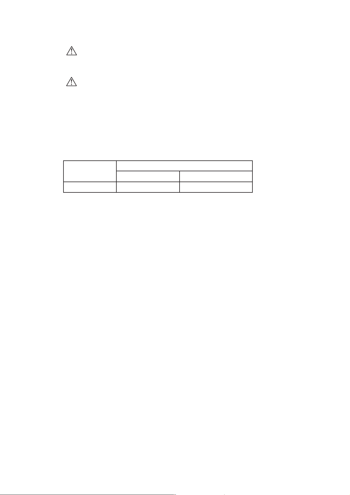
CAUTION
1.2 Operating Precautions
WARNING
1.2.1 Line Voltage and Fuse
Confirm that the power line voltage is correct before connecting the power cord.
The voltage range and fuse rating are indicated on the rear panel.
When replacing the fuse, turn the power switch off and disconnect the power cord
from the mains.
Voltage Range
Fuse
Rating LEADER Parts Number
90 to 250 V T0.63AL, time-lag 436 3555 005
1.2.2 Reverse Voltage
• Shorting the output connectors
Do not short any output connectors to prevent damage to the instrument.
• Do not apply external voltage to the output connectors. It can cause trouble.
1.2.3 Installation
Do not use the instrument in the following environments.
• High temperature environments
Do not place the instrument under direct sunlight or near a heater (e.g., stove).
Do not move the instrument from cold to warm environment abruptly, it may cause
condensation.
Operating temperature range: 0 to 40 °C
• High humidity environments
Do not place the instrument in the high humidity environment (e.g., bathroom, near
a humidor).
Operating humidity range: ≤ 90 % RH
• Dusty environments
1-2
Page 10

1.2.4 Mechanical Shock
Please be careful not to expose the instrument to other forms of severe mechanical
shock as this product contains shock sensitive precise parts.
1.2.5 Calibration
When calibration or service is required, contact your local LEADER agent.
1.2.6 Routine Maintenance
When cleaning the instrument, do not use such solvents as thinner or benzol which
will remove paint or damage the plastic surface. Use a soft cloth dampened with
neutral detergent.
Do not drop water or detergent, or insert metal object into the instrument while
cleaning. Otherwise, you run the risk of electrical shock or fire.
1-3
Page 11

2. SPECIFICATIONS
2.1 GENERAL
Model LT 416 is a precision test-signal source which provides four color systems of
NTSC, PAL, SECAM, and NTSC-4.43 for testing and adjusting all kind of video
products such as TV, VTR etc.
In addition of a composite signal output, the generator provides a Y/C output and a
component signal outputs (except SECAM) of Y/B-Y/R-Y and GBR so that it is
suitable to a production line for video products of component system.
RF output is easily selected by setting channel number while the channels are pre-
programmed by each countries.
15 test patterns including color bars, raster, convergence and circle satisfy the most
desired applications.
2.2 FEATURES
• Conforms to four standards (i.e., NTSC, PAL, SACAM, NTSC-4.43)
This generator is ideal for adjusting and testing TVs, VTRs, and AV equipments.
•S connector
An S connector is provided to output Y and C signals for adjusting AV equipments
with S connector.
• Component video signal output
This generator outputs the composite video signal and component video signal.
Since Y/ B-Y/ R-Y or G/ B/ R is output, the generator allows test signals for
component AV system adjustment and testing. (The SECAM color signals
(B-Y, R-Y) are not output.)
•RF setting
The channel plan based on the country system is provided for easier RF frequency
setting.
•Various test patterns
The 15 patterns including color bar and circle are provided for various adjustment
and test processes.
2-1
Page 12

2.3 Specifications
2.3.1 Composite Video Signal Output
(1) Color System: NTSC, PAL, SECAM, NTSC-4.43
(2) Scanning Method
NTSC/ NTSC-4.43: 525-line interlace scanning
PAL/ SECAM: 625-line interlace scanning
(Progressive scanning can be performed for all color systems when the
CIRCLE or CONVERGENCE pattern is selected.)
(3) Field frequency
NTSC: 59.94 Hz ±30 ppm
(60.06 Hz ±30 ppm for progressive
scanning)
PAL/ SECAM: 50 Hz ±30 ppm
(50.08 Hz ±30 ppm for progressive
scanning)
NTSC-4.43: 59.94 Hz ±150 ppm
(60.06 Hz ±150 ppm for progressive
scanning)
(4) Line frequency
NTSC: 15.734 kHz ±30 ppm
PAL/ SECAM: 15.625 kHz ±30 ppm
NTSC-4.43: 15.734 kHz ±150 ppm
(5) Subcarrier Frequency
NTSC: 3.579545 MHz ±30 ppm
PAL: 4.43361875 MHz ±30 ppm
NTSC-4.43: 4.43361875 MHz ±50 ppm
(Progressive scanning can be selected when
CIRCLE or CONVERGENCE patterns is
selected.)
(6) Video Generating System: Digital system using 4 fsc sampling (without
SECAM)
(7) Number of Quantitative Bits: 8 bits
(8) Output Impedance: 75Ω
(9) Output Level: 1 Vp-p ±50 mVp-p (Between sync tip and
100 % white)
0 to 1 Vp-p, continuous variable
2-2
Page 13

(10) Setup Level: NTSC: 0 % (“7.5 %” model optionally
available)
PAL/SECAM/NTSC 4.43 : 0 %
(11) Output connector
Variable output: BNC
Fixed output: RCA jack ............. 1
(12) Number of Outputs: 1 each ................. 1
2.3.2 Sync Signal
(1) Sync Signal
Amplitude
NTSC/ NTSC-4.43: 286 mVp-p ±14 mVp-p
PAL/ SECAM: 300 mVp-p ±15 mVp-p
Horizontal Sync Width: 4.7 µs ±200 ns (same spec.)
Ver tical Sync Width
NTSC/ NTSC-4.43: 3H
PAL/ SECAM: 2.5H
Ver tical Blanking Period
NTSC/ NTSC-4.43: 20H
PAL/ SECAM: 25H
(2) Color Burst
Amplitude
NTSC/ NTSC-4.43: 286 mVp-p ±23 mVp-p
PAL: 300 mVp-p ±24 mVp-p
Number of Cycles
NTSC: 9 cycles
PAL: 10 cycles
NTSC-4.43: 11 cycles
(3) SECAM Color Identification Signal
Amplitude
D’R Line: 540 mVp-p +40 mVp-p, -50 mVp-p
D’B Line: 500 mVp-p ±50 mVp-p
(4) SECAM Color (Back porch on the horizontal blanking period)
Amplitude
D’R Line: 215 mVp-p ±25 mVp-p
D’B Line: 167 mVp-p ±20 mVp-p
2-3
Page 14

2.3.3 Test Patterns
(1) Color Bar: 100/ 0/ 75/ 0 Full-field Color Bar
(2) Demodulator Pattern (Not output when the SECAM is selected)
PAL: Combination of normal and reversed B-Y
and R-Y for each line
NTSC: Combination of normal and reversed B-Y,
R-Y, I, and Q for each line
line n: R-Y, -(R-Y), B-Y, -(B-Y), R-Y, -(R-Y), B-Y,
-(B-Y)
line n+1: -(R-Y), R-Y, B-Y, -(B-Y), R-Y, -(R-Y),-(B-Y),
B-Y
line n: I, -I, Q, -Q, I, -I, Q, -Q
line n+1: -I, I, Q, -Q, I, -I, -Q, Q
(3) Multiburst
Frequency
NTSC/ NTSC-4.43: 0.5, 1.0, 2.0, 3.0, 3.58, 4.2 MHz
PAL/ SECAM: 0.5, 1.0, 2.0, 4.0, 4.8, 5.5 MHz
Amplitude: 100 %(*
)
(4) Raster
Output eight colors in combination with red, green and, blue
Color: 100 % white, yellow, cyan, green, magenta, red, blue, black
Amplitude: Same as color bars
(5) Window
Window Amplitude: 100 %(*
)
(6) Step
10 equal steps from 0 mV to 700 mV white
(7) Circle Pattern: White circle pattern (with black fringe) on the
convergence pattern
Color Burst: on/off selectable
Interlace/ Progressive: Selectable
(Flicker may occur on the border of convergence and circle patterns.)
(8) Convergence
Luminance Amplitude: 75 %(*
)
Number of Vertical Lines
NTSC/ NTSC-4.43: 17
PAL/ SECAM: 19
2-4
Page 15

Number of Horizontal Lines
NTSC/ NTSC-4.43: 14
PAL/ SECAM: 15
Horizontal Line Width: 2 lines
Number of Dots
NTSC/ NTSC-4.43: 16 x 13
PAL/ SECAM: 18 x 14
Dot Pulse Vertical Width: 2 lines
Color Burst: On/ off selectable
Interlace/ Progressive: Selectable
(*) Notes on pattern specifications
Signal amplitude (100 %) is as follows.
PAL/ SECAM: 700 mVp-p
NTSC/ NTSC-4.43: 714 mVp-p
Accuracy: Same as the composite signal
2.3.4 Y/ C Separation Output
Specifications: Same as the composite signal
Output Impedance: 75 Ω
Connector: S type
Number of Outputs: 1
2.3.5 Y, B-Y, R-Y Output
Output Signal (*2): Y, B-Y, R-Y
Y Output Amplitude
NTSC/ NTSC-4.43: 714 mVp-p ±36 mV
PAL: 700 mVp-p ±35 mV
Sync Signal Amplitude
NTSC/ NTSC-4.43: 286 mVp-p ±14 mV
PAL: 300 mVp-p ±15 mV
B-Y, R-Y Output Amplitude: 525 mVp-p ±26 mV
Output Impedance: 75 Ω
Connector: BNC
Number of Outputs: 1 each
(*2) B-Y and R-Y are output when the SECAM is selected;
Y is only output.
2-5
Page 16

2.3.6 R, G, B Output
Output Signal (*3): R, G, B, C.SYNC
R, G, B Output Amplitude: 700 mVp-p ±35 mV (NTSC, PAL,
NTSC-4.43)
C.SYNC Output Amplitude: C-MOS Level (NTSC, PAL, SECAM,
NTSC-4.43)
Output Impedance: 75 Ω
Connector: BNC
Number of Outputs: 1 each
(Pulse noise may be superimposed n the leading and trailing edges of the R, G
and B Sync signals.)
(*3) R, G, B are output when the SECAM is selected;
C.SYNC is only output.
2.3.7 RF Output
System
NTSC: M
PAL: B, D, G, H, I, K
SECAM: B, D, G, H, K, L
(The RF is disabled when the NTSC-4.43 is selected)
Carrier Frequency Range: VHF and UHF
Carrier Frequency Setting Method: Direct setting using programmed country
channel plan (Arbitrary frequency cannot be
set)
Modulation Polarity: Negative or Positive
Modulation System: Double sideband
Sound Signal
Intercarrier Frequency: 4.5, 5.5, 6.0, 6.5 MHz
Modulation Signal: 1 kHz ±200 Hz
Modulation System: FM or AM
Output Voltage
VHF: At least 1 mVrms (into 75 Ω)
UHF: At least 0.5 mVrms (into 75 Ω)
Number of Output: 1 (75 Ω, BNC)
Since a double sideband modulation system is used for the RF signal of the LT 416.
such parameters as P/S ratio do not conform to the official standards.
Therefore, video noise or audio noise may appear on a TV monitor, etc. when the RF
signal of the LT 416 is applied.
2-6
Page 17

2.3.8 Sound Output
Output Signal: 1 kHz ±100 Hz, sine wave
Amplitude: 1.2 Vp-p (into 600 Ω)
Output Impedance: 600 Ω
Number of Output: 1 (RCA jack)
2.3.9 General Specifications
Environmental Conditions
Operating Temperature: 0 to 40 °C
Operating Humidity: ≤ 90 % RH (without condensation)
Spec-Guaranteed Temperature: 10 to 30 °C
Spec-Guaranteed Humidity: ≤ 85 % RH (without condensation)
Operating Environment: Indoor use
Operating Altitude: Up to 2000 m
Overvoltage Category: ΙΙ
Pollution Degree: 2
Power Requirements: 90 to 250 VAC, 50/ 60 Hz Max.15 W
Dimensions: 426 (W) x 88 (H) x 300 (D) mm
(excluding projections)
Weight: 4.6 kg
Accessories: Power cord .............................. 1
Instruction manual ................... 1
2-7
Page 18

3. PANEL DESCRIPTION
Please refer to each item number described on Figure 3-1 and 3-2 for the described
instruction after 4.OPERATING PROCEDURE.
3.1 Front Panel
Figure 3-1 Front Panel
q POWER switch
Push this switch in to apply power. Release this switch for turning power off.
w Pattern keys
Select the pattern.
e R, G, B keys
Set raster color when the raster pattern is selected. Eight colors can be set in
combination with the keys pressed.
r PROGRESSIVE/ INTERLACE key
Select the scanning system when “CIRCLE” or “CONVERGENCE” is selected
by using the “Pattern Keys w.”
When the PROGRESSIVE is selected, the key LED light. When the INTERLACE
is selected, the key LED goes off.
t BURST key
Selects the color burst on or off when “CIRCLE” or “CONVERGENCE” is
selected by using the “Pattern Keys w.” When the signal with color burst is
output, the key LED lights; when the signal without color burst is output, the key
3-1
q
wuio!3 !4 !6 !7
ert y!0 !1 !2 !5 !8
Page 19

LED goes off.
In the SECAM system, this key is used to turn on or off the reference burst.
y COUNTRY/ CHANNEL u CHANNEL/ COUNTRY display i SELECT keys
This block is used to control the RF frequency.
Press the COUNTRY/ CHANNEL y when selecting the TV channel number and
country number.
When the COUNTRY LED light, the country number being selected is displayed
on the CANNEL/ COUNTRY display u.
When the CHANNEL LED light, the TV channel being selected is displayed on
the CHANNEL/ COUNTRY display u.
Use the SELECT i to select the country number and channel number.
The COUNTRY/ CHANNEL y is also used to turn on or off the sound subcarrier
on the RF output.
o SYSTEM
Selects the color system.
!0 AUDIO OUTPUT connector
Outputs 1 kHz sine wave in fixed level.
RCA jack is used. Output impedance is 600 Ω.
!1 VIDEO OUTPUT connector
Outputs composite video signal in fixed level.
RCA jack is used. Output impedance is 75 Ω.
!2 Y/C OUTPUT connector
Outputs Y and C video signals in fixed level.
S connector is used. Output impedance for both Y and C is 75 Ω.
!3 VIDEO OUTPUT !4 LEVEL !5 OUTPUT
This group is used to control the composite video signal output level.
OUTPUT connector is BNC, and output impedance is 75 Ω.
The level is calibrated at the PRESET (detent) position.
The output level can be set from 0 V (MIN, immediately before the detent
position) to the preset level (MAX) by rotating the OUTPUT LEVEL control.
!6 RF OUTPUT !7 LEVEL !8 OUTPUT
This group is used to control the RF output level.
OUTPUT connector is BNC, and output impedance is 75 Ω.
OUTPUT LEVEL control sets the output level. Clockwise rotation increases
output level.
3-2
Page 20

3.2 Rear Panel
This section describes the rear panel according to Figure 3-2.
Figure 3-2 Rear Panel
!9 Y, B-Y, R-Y connectors
Output component video signal with fixed level. Luminance signal (Y) and color
difference signal (B-Y, R-Y) are output.
Output impedance of each connector is 75 Ω.
@0 R, G, B, C.SYNC connectors
Output RGB video signal and composite sync signal with fixed level. Output
impedance of R, G, and B connectors are 75 Ω. The C.SYNC is output in C-MOS
level.
@1 Inlet
Connect the accessory power cord.
Usable AC voltage range is 90 to 250 V, universal.
@2 Fuse holder
The fuse rating is indicated on the rear panel. When replacing the fuse, rotate the
fuse holder cap counterclockwise using a Phillips screwdriver to remove the cap.
@3 Ground terminal
This terminal is connected to the chassis, and is used for grounding.
@4 Serial number plate
Instrument serial number. Provide this number when contacting us.
3-3
@0
@1
@2
@4 @3
!9
Page 21

4. OPERATING PROCEDURE
4.1 Turning Power On
4.1.1 Connecting Power Plug
Check the mains voltage and current capacity for correct before connecting the
instrument.
4.1.2 Turning Power On
Always confirm that the instrument is not in a volatile or flammable environment
before turning the power on.
4.1.3 Warm-Up Time
You should allow the instrument to warm up for at least 30 minutes.
4.2 Connection
4.2.1 Cable
Ta ble 4-1 lists a cable to be used.
Ta ble 4-1
* Do not apply ±1 V (DC or AC peak) or higher external voltage to the output
connectors.
4-1
!0 AUDIO OUTPUT
!1 VIDEO OUTPUT
!2 Y/C OUTPUT
!5 OUTPUT
!8 OUTPUT
!9 Y, B-Y, R-Y
@0 R, G, B, C.SYNC
Sound
Composite video
Y/C difference signal
Composite video
RF
Y
B-Y
R-Y
R
G
B
C.SYNC
RCA
RCA
S connector
BNC
BNC
BNC
BNC
BNC
BNC
BNC
BNC
BNC
Shield wire
75Ω coaxial cable
S cable
75Ω coaxial cable
75Ω coaxial cable
75Ω coaxial cable
75Ω coaxial cable
75Ω coaxial cable
75Ω coaxial cable
75Ω coaxial cable
75Ω coaxial cable
Shield wire
Output Connector Signal Connector cable
Page 22

4.2.2 Termination
When the equipment under test is connected, the cable end should be terminated
with appropriate impedance for correct output level. Table 4-2 shows the output
impedance and termination impedance for each connector.
Ta ble 4-2
4.3 Color System Selection
Pressing the SYSTEM key o selects the color system
(i.e., NTSC → PAL → SECAM → NTSC-4.43) sequentially. Lit LED indicates the
selected system.
Pressing this key obtains the latest settings (e.g., pattern, RF frequency) related to
each system.
4-2
!0 AUDIO OUTPUT
!1 VIDEO OUTPUT
!2 Y/C OUTPUT
!5 OUTPUT
!8 OUTPUT
!9 Y, B-Y, R-Y OUTPUT
@0 R, G, B,
C.SYNC OUTPUT
Sound
Composite video
Y/C difference signal
Composite video
RF
Y
B-Y
R-Y
R
G
B
C.SYNC
600 Ω
75 Ω
75 Ω
75 Ω
75 Ω
75 Ω
75 Ω
75 Ω
75 Ω
75 Ω
75 Ω
C-MOS output
Output Connector Signal Ternination
Page 23

4.4 Composite Video Signal
4.4.1 VIDEO OUTPUT connector
(1) Preset Output Level
When the OUTPUT LEVEL control !4 is set to PRESET position, the output level
between sync tip and 100 % white is 1 Vp-p (into 75 Ω).
Figure 4-1 Preset position
(2) Variable Output Level
The output level can be set from 0 V (MIN, immediately before the detent
position) to the preset level (MAX) by rotating the OUTPUT LEVEL control !4.
Clockwise rotation increases output level.
4.4.2 Fixed VIDEO OUTPUT Connector !1
The output level between sync tip and 100% white is 1 Vp-p (into 75 Ω) regardless of
the OUTPUT LEVEL control !4 setting.
4.5 Component Video Signal
4.5.1 Y, B-Y, R-Y Connectors !9
Use the Y, B-Y, R-Y connectors !9 to output Luminance and color difference signals.
Output levels are fixed regardless of the LEVEL control !4.
The SECAM color signals (B-Y, R-Y) are not output.
4.5.2 R, G, B, C.SYNC Connectors @0
Use the R, G, B, C.SYNC connectors @0 to output R, G, and B signals. The C.SYNC
is used to synchronize the R, G, and B signals. Output levels are fixed regardless of
the LEVEL control !4.
The SECAM only outputs C.SYNC.
4-3
!4 LEVEL
Page 24

4.6 Y/C Separation Signal
4.6.1 Y/C OUTPUT Connector !2
The Y/C OUTPUT connector !2 is used to connect an unit equipped with S connector.
Output level is fixed; same as the composite signal.
4.7 Audio Signal
4.7.1 AUDIO OUTPUT Connector !0
The AUDIO OUTPUT connector !0 outputs audio signal.
The signal is 1 kHz, 1.2 Vp-p (into 600 Ω) fixed. Pin jack is used.
4.8 RF Signal
4.8.1 OUTPUT Connector !8
Use the OUTPUT connector !8 to output RF signal. This connector cannot be used
when the NTSC 4.43 is selected.
4.8.2 Level Control !7
Use the RF OUTPUT LEVEL control !7. to set output level.
Rotating the control clockwise increases RF output level; fully clockwise for maximum
output level, and vise versa.
Figure 4-2 RF OUTPUT group
4.9 Pattern Settings
(1) Using Pattern Key w
Use the Pattern key w to select the pattern. Selected pattern key LED lights.
The DEM key is disable when the SECAM is selected.
(2) Raster Color Settings
The raster color can be selected in combination with the R, G, and B keys e
when the RASTER pattern is selected by using the pattern key w.
(Figure 4-3 shows the key combinations to select a green raster.)
Ta ble 4-3 shows color and key combinations.
Ta ble 4-3 Raster color and key combinations
4-4
White Black Red Green Blue Yellow Cyan Magenta
R Key ON OFF ON OFF OFF ON OFF ON
G Key ON OFF OFF ON OFF ON ON OFF
B Key ON OFF OFF OFF ON OFF ON ON
* ON : LED lights. OFF : LED goes off.
!7 LEVEL
!8 OUT PUT connector
Page 25

Figure 4-3 Key combinations to select green
(3) Interlace/Progressive Scanning Selection
The SCAN key r is used to select the scanning system when the CIRCLE or
CONVERGENCE pattern is selected by using the Pattern key w.
The key operation is toggled.
When the PROGRESSIVE is selected, the indicator lights. When the INTERLACE
is selected, the indicator goes off.
If the TV screen becomes difficult to watch due to flickering, select
PROGRESSIVE to reduce the amount of flicker.
(4) Color Burst, Reference Burst On/Off
The BURST key t is used to set the color burst or reference burst on or off when
the CIRCLE or CONVERGENCE pattern is selected by using the Pattern key w.
The key operation is toggled.
The indicator lights when the burst is set on, and vise versa.
If the TV screen becomes difficult to watch due to the coloring of the vertical line
edge, set the burst off to reduce this effect.
The BURST⑤ key is used to set the color burst on or off when the NTSC, PAL, or NTSC
4.43 is selected by using SYSTEM key
⑨
. The BURST ⑤key is also used to set the
reference burst on or off when the SECAM is selected by using SYSTEM key
⑨
.
4.10 RF Channel Settings
4.10.1 Setting Method
(1) About RF Output Settings
The combination of country number (COUNTRY) and channel (CHANNEL) is
used for setting the RF output frequency and RF system (i.e., modulation system,
sound subcarrier).
See 5.3 "Channel Plan Table" to select the desired RF frequency and RF system.
Note that arbitrary RF frequency and RF system cannot be set.
4-5
e R,G,B
LED off
LED on
LED off
Page 26

(2) Setting Procedure
• Use the COUNTRY/CHANNEL key y, COUNTRY/CHANNEL display u, and
SELECT key i for setting RF system.
• The COUNTRY/CHANNEL key y operation is toggled.
The COUNTRY LED lights in country number setting mode; the CHANNEL LED
lights in channel number setting mode.
• The CHANNEL/COUNTRY display u shows the country number (COUNTRY
LED on) or channel number (CHANNEL LED on).
• The SELECT key i is used to select the country number (COUNTRY LED on)
or channel number (CHANNEL LED on).
Pressing Up key increments the number by one; Down key Decrements the
number by one.
• Refer to Section 4.10.6, "Sound Subcarrier Level Selection" for detail.
Figure 4-4 RF control group
4.10.2 Setting Procedure
(1) About Country Number
A country number is attached to each channel plan. To select the channel plan of
country or region to be set, select the corresponding number.
(2) Country Number Selection
Refer to Step (2) in Section 4.10.1, "RF Output Settings."
(3) Finding Desired Channel Plan
Example to set the channel plan of Germany VHF:
According to the Section 5.2, "Broadcast System/Channel Plan by Country/Region,"
the channel plan "5" will be obtained.
4-6
i SELECT
y COUNTRY/CHANNEL
COUNTRY/CHANNEL DISPLAY
u
Page 27

4.10.3 Selecting Channel
(1) About Channel Number
The channel number is displayed in two digits.
Alphanumeric characters are used for the channel numbers of some channel plan.
This generator converts alphanumeric channel number into numeric ones for
display convenience.
Section "5.3, "Channel Plan Table" shows the correspondence between both
types of numbers.
(2) Channel Number Selection
Refer to Step (2) in Section 4.10.1, "RF Output Settings."
(3) Numeric Channel Number
The actual channel number is displayed.
(4) Alphanumeric Channel Number
The actual channel number is converted into alphanumeric channel number and
displayed.
Example: When the Australia VHF channel is selected, the actual channel number
"5A" is converted into "7" and displayed.
4.10.4 Restriction by「SYSTEM ⑨」
The color system must be selected by using SYSTEM key ⑨ before selecting the
country number. Otherwise, the country number cannot be selected.
4.10.5 RF Modulation
A double sideband modulation system is used for the RF signal.
4-7
Page 28

4.10.6 RF Setting Example
This section describes an example to set the FRANCE VHF FB channel.
(1) See Section 5.2, "Broadcast System/Channel Plan by Country/Region" and find
"France. "According to the table, the SECAM system and country number "25"
will be obtained.
Finland PAL CCIR VHF(B) 5 CCIR UHF(G) 7
Puerto Rico NTSC USA [VHF] 0 USA UHF 1
France SECAM FRANCE [VHF] 25
FRANCE
[UHF] 26
Polynesia SECAM FOT [VHF] 28
Bulugaria SECAM OIRT [VHF](D) 23 CCIR UHF(K) 24
(2)
Refer to Section 5.3, "Channel Plan Table" and find the "SECAM FRANCE [VHF]" table.
(3) Select the SECAM by pressing the SYSTEM key o.
(4)
Press the COUNTRY/CHANNEL key yfor the country selection mode (COUNTRY).
(5)
Display "25" on the COUNTRY/CHANNEL display uby pressing the SELECT key i.
(6)
Press the COUNTRY/CHANNEL key yfor the channel selection mode (CHANNEL).
(7)
Display "2" on the COUNTRY/CHANNEL display u by pressing the SELECT key i
.
4.10.7 Sound Subcarrier Level Selection
The sound subcarrier signal is added to the RF signal when the instrument is shipped
from the factory. The subcarrier level can be reduced about 20 dB.
To reduce the level, hold down the COUNTRY/CHANNEL key y until "oF" appears on
the COUNTRY/CHANNEL display u.
To obtain the original level, hold down the COUNTRY/CHANNEL key y until "on"
appears on the COUNTRY/CHANNEL display u.
A subcarrier noise may be superimposed on the RF signal. Set the subcarrier "oF," in
this case.
4-8
ch. No. LED display
SECAM FRANCE [VHF]
fv (MHz) fs (MHz)
F A
F B
F C 1
1
2
3
47.75
55.75
60.50
54.25
62.25
67.00
Countries/Areas Number
RF System
25
L
Page 29

4.11 Battery Backup
4.11.1 Backup Capability
This generator retains the setting conditions (e. g., system, pattern settings,country
number,TV channel number) even when the power is turned off.
Data is retained about 14 days with a fully charged backup battery (ambient
temperature: ≤ 40 °C ,relative humidity: ≤ 80 % ) ,
4.11.2 Battery
Rechargeable battery is used.
4.11.3 Battery Life
When backup period becomes short, the battery should be replaced. When replacing
the battery, contact your local LEADER agent.
WARNING
4.12 Fuse Replacement
When the fuse burns out, replace it according to the procedure below.
(1) Remove the power cord from the mains to prevent accident.
(2) Rotate the fuse holder cap counterclockwise using a Phillips screwdriver to
remove the cap.
(3) Replace damaged fuse with new one.
(4) Use only the fuse of correct type and rating for replacement.
Do not use such wire as copper lead. It can cause fire.
(5) After the fuse is replaced, mount the cap surely.
(6) Excessive tightening may broken the cap. If it is broken, the fuse holder must be
replaced to prevent trouble. In this case, contact your local LEADER agent.
4-9
Page 30

5. CHANNEL PLAN
5.1 Broadcast System
Ta ble 5-1 lists the major parameters of the broadcast system.
Ta ble 5-1 Major parameters of broadcasting system
5.2 Broadcast System/Channel Plan for Country/ Region
*Note that the contents with regard to the channel plan are only for your reference
because estimated information is listed for some countries/regions.
Ta ble 5-2 Broadcast System/Channel Plan by Country/Region
5-1
System
Channel Bandwidth (MHz)
Sound Subcarrier Frequency
(MHz)
Video Modulation Polarity
Sound Modulation System
M
6
4. 5
–
FM
B
7
5. 5
–
FM
G
8
5. 5
–
FM
H
8
5. 5
–
FM
I
8
6
–
FM
D, K
8
6. 5
–
FM
L
8
6. 5
+
AM
Countries/Areas
Color
System
Afghanistan PAL CCIR VHF(B) 5
Albania PAL ITALY VHF 14 CCIR UHF(G) 7
Algeria PAL CCIR VHF(B) 5 CCIR UHF(G) 7
Angola PAL ANGOLA VHF 12 CCIR UHF(G) 7
Australia PAL
AUSTRALIA VHF
15
AUSTRALIA UHF
16
Austria PAL CCIR VHF(B) 5 CCIR UHF(G) 7
Bahamas NTSC USA VHF 0
Bahrain PAL CCIR VHF(B) 5 CCIR UHF(G) 7
Bangladesh PAL CCIR VHF(B) 5
Barbados NTSC USA VHF 0
Belgium PAL CCIR VHF(B) 5 CCIR UHF(H) 8
Belize
Benin SECAM FOT VHF 28 CCIR UHF(K) 24
Bermuda NTSC USA VHF 0
Bolivia NTSC USA VHF 0
Bosnia Herzegovina PAL CCIR VHF(B) 5 CCIR UHF(G) 7
Botswana PAL
SOUTH AFRICA VHF(I)
18 CCIR UHF(I) 9
VHF
Co. No. System
UHF
Co. No. System
Page 31

5-2
Brunei PAL CCIR VHF(B) 5
Bulgaria SECAM OIRT VHF(D) 23 CCIR UHF(K) 24
Burkina Faso SECAM FOT VHF 28 CCIR UHF(K) 24
Burundi SECAM FOT VHF 28 CCIR UHF(K) 24
Cambodia PAL CCIR VHF(B) 5
Cameroun PAL CCIR VHF(B) 5 CCIR UHF(G) 7
Canada NTSC USA VHF 0 USA UHF 1
Central Africa Republic SECAM FOT VHF 28 CCIR UHF(K) 24
Chad SECAM OIRT VHF(D) 23 CCIR UHF(K) 24
Chile NTSC USA VHF 0 USA UHF 1
China PAL CHINA VHF 19 CHINA UHF 20
CIS SECAM OIRT VHF(D) 23 CCIR UHF(K) 24
Congo SECAM OIRT VHF(D) 23 CCIR UHF(K) 24
Costa Rica NTSC USA VHF 0 USA UHF 1
Coto d'Ivoire SECAM
IVORY COAST VHF
27 CCIR UHF(K) 24
Croatia PAL CCIR VHF(B) 5 CCIR UHF(G) 7
Cuba NTSC USA VHF 0 USA UHF 1
Cyprus PAL CCIR VHF(B) 21 CCIR UHF(G) 22
Czecho SECAM OIRT VHF(D) 23 CCIR UHF(K) 24
Denmark PAL CCIR VHF(B) 5 CCIR UHF(G) 7
Diego Garcia NTSC USA VHF 0
Djibouti SECAM FOT VHF 28
Dominica (Commonwelth. of)
NTSC USA VHF 0
Dominica Republic NTSC USA VHF 0 USA UHF 1
Ecuador NTSC USA VHF 0 USA UHF 1
Egypt PAL CCIR VHF(B) 21 CCIR UHF(G) 22
El Salvador NTSC USA VHF 0 USA UHF 1
England CCIR UHF(G) 7
Ethiopia PAL CCIR VHF(B) 5 CCIR UHF(G) 7
Fiji PAL CCIR VHF(B) 5
Finland PAL CCIR VHF(B) 5 CCIR UHF(G) 7
France SECAM FRANCE VHF 25 FRANCE UHF 26
French Polynesia SECAM FOT VHF 28
Gabonese SECAM FOT VHF 28 CCIR UHF(K) 2
Gambia PAL
SOUTH AFRICAVHF(I)
5 CCIR UHF(I) 7
Countries/Areas
Color
System
VHF
System Co. No.
UHF
System Co. No.
Page 32

5-3
Countries/Areas
Color
System
Gernany PAL CCIR VHF(B) 5 CCIR UHF(G) 7
Ghana PAL CCIR VHF(B) 5
Gibraltar PAL CCIR VHF(B) 5 CCIR UHF(G) 7
Greenland NTSC USA VHF 0
Grenada
Guam NTSC USA VHF 0
Guatemala NTSC USA VHF 0 USA UHF 1
Guinea SECAM FOT VHF 28
PA L CCIR UHF(K) 10
Guyana
Guyana-Bissau PAL
SOUTH AFRICA VHF(I)
18 CCIR UHF(I) 9
Haiti NTSC USA VHF 0
Hawaii NTSC USA VHF 0
Hellenic Republic PAL CCIR VHF(B) 21 CCIR UHF(G) 22
Holland PAL CCIR VHF(B) 5 CCIR UHF(G) 7
Hong Kong PAL CCIR UHF(I) 9
Hungary SECAM OIRT VHF(D) 23 CCIR UHF(K) 24
Iceland PAL CCIR VHF(B) 5
India PAL CCIR VHF(B) 5 CCIR UHF(G) 7
Indonesia PAL
INDONESIA VHF
11
Iran SECAM CCIR VHF(B) 21 CCIR UHF(G) 22
Iraq SECAM CCIR VHF(B) 21 CCIR UHF(G) 22
Ireland PAL IRELAND VHF 13 CCIR UHF(I) 9
Israel PAL CCIR VHF(B) 5 CCIR UHF(I) 9
Italy PAL ITALY VHF 14 CCIR UHF(G) 7
Jamaica NTSC USA VHF 0
Japan NTSC JAPAN VHF 2 JAPAN UHF 3
Johnston Is. (USA) NTSC USA VHF 0
Jordan PAL CCIR VHF(B) 5 CCIR UHF(G) 7
KenyaPAL CCIR VHF(B) 5 CCIR UHF(G) 7
Korea NTSC USA VHF 0 USA UHF 1
Kuwait PAL CCIR VHF(B) 5 CCIR UHF(G) 7
Lebanon SECAM CCIR VHF(B) 21 CCIR UHF(G) 22
Lesotho PAL
SOUTH AFRICA VHF(I)
18 CCIR UHF(I) 9
iberia PAL CCIR VHF(B) 5 CCIR UHF(G) 7
VHF
Co. No. System
UHF
Co. No. System
Page 33

5-4
Countries/Areas
Color
System
Libya PAL CCIR VHF(B) 5 CCIR UHF(G) 7
Luxembourg PAL CCIR VHF(B) 5 CCIR UHF(G) 7
Macao Area PAL CCIR UHF(I) 9
Macedonia PAL CCIR VHF(B) 5 CCIR UHF(G) 7
Madagascar SECAM FOT VHF 28 CCIR UHF(K) 24
Malawi PAL
SOUTH AFRICA VHF(I)
18 CCIR UHF(I) 9
Malaysia PAL CCIR VHF(B) 5 CCIR UHF(G) 7
Maldives PAL CCIR VHF(B) 5
Mali SECAM CCIR VHF(B) 21 CCIR UHF(G) 22
Malta PAL CCIR VHF(B) 5
Mauritania SECAM CCIR VHF(B) 21
Mauritius SECAM CCIR VHF(B) 21 CCIR UHF(G) 22
Mexico NTSC USA VHF 0 USA UHF 1
Micronesia NTSC USA VHF 0
Midway Is. (USA) NTSC USA VHF 0
Monaco PAL CCIR UHF(G) 7
SECAM FRANCE VHF 25 CCIR UHF(G) 7
Mongolia SECAM OIRT VHF(D) 23
Morocco SECAM
MOROCCO VHF(B)
29 CCIR UHF(G) 22
Mozambique CCIR UHF(G) 7
Myanmar NTSC USA VHF 0
Namibia PAL
SOUTH AFRICA VHF(I)
18 CCIR UHF(I) 9
Nepal PAL CCIR VHF(B) 5
New Caledonia SECAM FOT VHF 28
New Zealand PAL
NEW ZEALAND VHF
17 CCIR UHF(G) 7
Nicaragua NTSC USA VHF 0 USA UHF 1
Niger SECAM FOT VHF 28 CCIR UHF(K) 24
Nigeria PAL CCIR VHF(B) 5 CCIR UHF(I) 9
North Korea PAL OIRT VHF(D) 6 CCIR UHF(K) 10
Norway PAL CCIR VHF(B) 5 CCIR UHF(G) 7
Oman PAL CCIR VHF(B) 5 CCIR UHF(G) 7
Pakistan PAL CCIR VHF(B) 5 CCIR UHF(G) 7
Panama NTSC USA VHF 0 USA UHF 1
Papua New Guinea PAL CCIR VHF(B) 5 CCIR UHF(G) 7
Philippines NTSC USA VHF 0 USA UHF 1
VHF
Co. No. System
UHF
Co. No. System
Page 34

5-5
Countries/Areas
Color
System
Poland SECAM OIRT VHF(D) 23 CCIR UHF(K) 24
Por tugal PAL CCIR VHF(B) 5 CCIR UHF(G) 7
Puerto Rico NTSC USA VHF 0 USA UHF 1
Qatar PAL CCIR VHF(B) 5 CCIR UHF(G) 7
Romania PAL CCIR VHF(D) 6 CCIR UHF(K) 10
Rwanda SECAM FOT VHF 28 CCIR UHF(K) 24
Sao Tome & Principe PAL CCIR VHF(B) 5
Saudi Arabia SECAM CCIR VHF(B) 21 CCIR UHF(G) 22
PA L CCIR VHF(B) 5
Seychelles PAL CCIR VHF(B) 5 CCIR UHF(G) 7
Sierra Leone PAL CCIR VHF(B) 5 CCIR UHF(G) 7
Singapore PAL CCIR VHF(B) 5 CCIR UHF(G) 7
Slovakia SECAM OIRT VHF(D) 23 CCIR UHF(K) 24
Slovenia PAL CCIR VHF(B) 5 CCIR UHF(G) 7
Somalia PAL CCIR VHF(B) 5 CCIR UHF(G) 7
South Africa PAL
SOUTH AFRICA VHF(I)
18 CCIR UHF(I) 9
Spain PAL CCIR VHF(B) 5 CCIR UHF(G) 7
Srbije & Montenegro PAL CCIR VHF(B) 5 CCIR UHF(G) 7
Sri Lanka PAL CCIR VHF(B) 5 CCIR UHF(G) 7
St. Christopher & Nevis
St. Lucia NTSC USA VHF 0
St. Vincent
Sudan PAL CCIR VHF(B) 5 CCIR UHF(G) 7
Surinam NTSC USA VHF 0
Swaziland PAL CCIR VHF(B) 5 CCIR UHF(G) 7
Sweden PAL CCIR VHF(B) 5 CCIR UHF(G) 7
Swiss PAL CCIR VHF(B) 5 CCIR UHF(G) 7
Taiwan Areas NTSC TAIWAN VHF 4
Tanzania PAL
SOUTH AFRICA VHF(I)
18 CCIR UHF(I) 9
Thailand PAL CCIR VHF(B) 5 CCIR UHF(G) 7
Togo SECAM FOT VHF 28 CCIR UHF(K) 24
Tr inidad & Tobago NTSC USA VHF 0
Tunisia PAL CCIR VHF(B) 5 CCIR VHF(B) 7
SECAM CCIR VHF(B) 21 CCIR VHF(B) 22
Tu rkey PA L CCIR VHF(B) 5 CCIR UHF(G) 7
Uganda PAL CCIR VHF(B) 5 CCIR UHF(G) 7
VHF
Co. No. System
UHF
Co. No. System
Page 35

5-6
Countries/Areas
Color
System
VHF
United Arab Emirates PAL CCIR VHF(B) 5
USA NTSC USA VHF 0 USA UHF 1
Venezuela NTSC USA VHF 0
Viet Nam PAL CCIR VHF(D) 6 CCIR UHF(K) 10
Virginia Is. (USA) NTSC USA VHF 0
Western Samoa NTSC USA VHF 0
Yemen PAL CCIR VHF(B) 5 CCIR UHF(I) 9
Zaire SECAM FOT VHF 28 CCIR UHF(K) 24
Zambia PAL CCIR VHF(B) 5 CCIR UHF(G) 7
Zimbabwe PAL CCIR VHF(B) 5 CCIR UHF(G) 7
Co. No. System
UHF
Co. No. System
Page 36

5.3 Channel Plan Table
5.3.1 How to use Channel Plan Table
5-7
ch. No. LED display
NTSC USA [VHF]
fv (MHz) fs (MHz)
2
3
4
5
6
7
8
2
3
4
5
6
7
8
55.25
61.25
67.25
77.25
83.25
175.25
181.25
59.75
65.75
71.75
81.75
87.75
179.75
185.75
Countries/Areas Number
RF System
0
M
Color System
Sound Frequency
Countries/Areas Number
Video Frequency
Channel number displayed
Actual channel number
Channel Plan
Ta ble 5-1
Page 37

5.3.2 Channel Plan Table
5-8
LED display
NTSC USA [VHF]
fv (MHz) fs (MHz)
2
3
4
5
6
7
8
9
10
11
12
13
2
3
4
5
6
7
8
9
10
11
12
13
55.25
61.25
67.25
77.25
83.25
175.25
181.25
187.25
193.25
199.25
205.25
211.25
59.75
65.75
71.75
81.75
87.75
179.75
185.75
191.75
197.75
203.75
209.75
215.75
Countries/Areas Number
RF System
0
M
LED display
NTSC USA [UHF] (cont'd)
fv (MHz) fs (MHz)
38
39
40
41
42
43
44
45
46
47
48
49
50
51
52
53
54
55
56
57
58
59
60
61
62
63
64
65
66
67
68
69
70
71
72
73
74
75
76
77
78
79
80
81
82
83
38
39
40
41
42
43
44
45
46
47
48
49
50
51
52
53
54
55
56
57
58
59
60
61
62
63
64
65
66
67
68
69
70
71
72
73
74
75
76
77
78
79
80
81
82
83
615.25
621.25
627.25
633.25
639.25
645.25
651.25
657.25
663.25
669.25
675.25
681.25
687.25
693.25
699.25
705.25
711.25
717.25
723.25
729.25
735.25
741.25
747.25
753.25
759.25
765.25
771.25
777.25
783.25
789.25
795.25
801.25
807.25
813.25
819.25
825.25
831.25
837.25
843.25
849.25
855.25
861.25
867.25
873.25
879.25
885.25
619.75
625.75
631.75
637.75
643.75
649.75
655.75
661.75
667.75
673.75
679.75
685.75
691.75
697.75
703.75
709.75
715.75
721.75
727.75
733.75
739.75
745.75
751.75
757.75
763.75
769.75
775.75
781.75
787.75
793.75
799.75
805.75
811.75
817.75
823.75
829.75
835.75
841.75
847.75
853.75
859.75
865.75
871.75
877.75
883.75
889.75
Countries/Areas Number
RF System
1
M
LED display
NTSC USA [UHF]
fv (MHz) fs (MHz)
14
15
16
17
18
19
20
21
22
23
24
25
26
27
28
29
30
31
32
33
34
35
36
37
14
15
16
17
18
19
20
21
22
23
24
25
26
27
28
29
30
31
32
33
34
35
36
37
471.25
477.25
483.25
489.25
495.25
501.25
507.25
513.25
519.25
525.25
531.25
537.25
543.25
549.25
555.25
561.25
567.25
573.25
579.25
585.25
591.25
597.25
603.25
609.25
475.75
481.75
487.75
493.75
499.75
505.75
511.75
517.75
523.75
529.75
535.75
541.75
547.75
553.75
559.75
565.75
571.75
577.75
583.75
589.75
595.75
601.75
607.75
613.75
Countries/Areas Number
RF System
1
M
Ta ble 5-3
Ta ble 5-2
ch. No. ch. No.
ch. No.
Page 38

5-9
LED display
NTSC JAPAN [VHF]
fv (MHz) fs (MHz)
1
2
3
4
5
6
7
8
9
10
11
12
1
2
3
4
5
6
7
8
9
10
11
12
91.25
97.25
103.25
171.25
177.25
183.25
189.25
193.25
199.25
205.25
211.25
217.25
95.75
101.75
107.75
175.75
181.75
187.75
193.75
197.75
203.75
209.75
215.75
221.75
Countries/Areas Number
RF System
2
M
LED display
NTSC JAPAN [UHF] (cont'd)
fv (MHz) fs (MHz)
39
40
41
42
43
44
45
46
47
48
49
50
51
52
53
54
55
56
57
58
59
60
61
62
39
40
41
42
43
44
45
46
47
48
49
50
51
52
53
54
55
56
57
58
59
60
61
62
627.25
633.25
639.25
645.25
651.25
657.25
663.25
669.25
675.25
681.25
687.25
693.25
699.25
705.25
711.25
717.25
723.25
729.25
735.25
741.25
747.25
753.25
759.25
765.25
631.75
637.75
643.75
649.75
655.75
661.75
667.75
673.75
679.75
685.75
691.75
697.75
703.75
709.75
715.75
721.75
727.75
733.75
739.75
745.75
751.75
757.75
763.75
769.75
Countries/Areas Number
RF System
3
M
LED display
NTSC JAPAN [UHF]
fv (MHz) fs (MHz)
13
14
15
16
17
18
19
20
21
22
23
24
25
26
27
28
29
30
31
32
33
34
35
36
37
38
13
14
15
16
17
18
19
20
21
22
23
24
25
26
27
28
29
30
31
32
33
34
35
36
37
38
471.25
477.25
483.25
489.25
495.25
501.25
507.25
513.25
519.25
525.25
531.25
537.25
543.25
549.25
555.25
561.25
567.25
573.25
579.25
585.25
591.25
597.25
603.25
609.25
615.25
621.25
475.75
481.75
487.75
493.75
499.75
505.75
511.75
517.75
523.75
529.75
535.75
541.75
547.75
553.75
559.75
565.75
571.75
577.75
583.75
589.75
595.75
601.75
607.75
613.75
619.75
625.75
Countries/Areas Number
RF System
3
M
Ta ble 5-5
Ta ble 5-4
ch. No.
ch. No.
ch. No.
Page 39

5-10
LED display
NTSC TAIWAN [VHF]
fv (MHz) fs (MHz)
7
8
9
10
11
12
7
8
9
10
11
12
175.25
181.25
187.25
193.25
199.25
205.25
179.75
185.75
191.75
197.75
203.75
209.75
Countries/Areas Number
RF System
4
M
Ta ble 5-6
ch. No.
LED display
PAL CCIR(B)[VHF]
fv (MHz) fs (MHz)
2
3
4
5
6
7
8
9
10
11
12
2
3
4
5
6
7
8
9
10
11
12
48.25
55.25
62.25
175.25
182.25
189.25
196.25
203.25
210.25
217.25
224.25
53.75
60.75
67.75
180.75
187.75
194.75
201.75
208.75
215.75
222.75
229.75
Countries/Areas Number
RF System
5
B
Ta ble 5-7
LED display
PAL OIRT(D)[VHF]
fv (MHz) fs (MHz)
R1
R2
R3
R4
R5
R6
R7
R8
R9
R10
R11
R12
1
2
3
4
5
6
7
8
9
10
11
12
49.75
59.25
77.25
85.25
93.25
175.25
183.25
191.25
199.25
207.25
215.25
223.25
56.25
65.75
83.75
91.75
99.75
181.75
189.75
197.75
205.75
213.75
221.75
229.75
Countries/Areas Number
RF System
6
D
Ta ble 5-8
ch. No. ch. No.
Page 40

LED display
PAL CCIR(G)[VHF]
fv (MHz) fs (MHz)
21
22
23
24
25
26
27
28
29
30
31
32
33
34
35
36
37
38
39
40
41
42
43
44
45
46
47
48
49
50
51
52
53
54
55
56
57
58
59
60
61
62
63
64
65
66
67
68
69
21
22
23
24
25
26
27
28
29
30
31
32
33
34
35
36
37
38
39
40
41
42
43
44
45
46
47
48
49
50
51
52
53
54
55
56
57
58
59
60
61
62
63
64
65
66
67
68
69
471.25
479.25
487.25
495.25
503.25
511.25
519.25
527.25
535.25
543.25
551.25
559.25
567.25
575.25
583.25
591.25
599.25
607.25
615.25
623.25
631.25
639.25
647.25
655.25
663.25
671.25
679.25
687.25
695.25
703.25
711.25
719.25
727.25
735.25
743.25
751.25
759.25
767.25
775.25
783.25
791.25
799.25
807.25
815.25
823.25
831.25
839.25
847.25
855.25
476.75
484.75
492.75
500.75
508.75
516.75
524.75
532.75
540.75
548.75
556.75
564.75
572.75
580.75
588.75
596.75
604.75
612.75
620.75
628.75
636.75
644.75
652.75
660.75
668.75
676.75
684.75
692.75
700.75
708.75
716.75
724.75
732.75
740.75
748.75
756.75
764.75
772.75
780.75
788.75
796.75
804.75
812.75
820.75
828.75
836.75
844.75
852.75
860.75
Countries/Areas Number
RF System
7
G
Ta ble 5-9
LED display
PAL CCIR(H)[UHF]
fv (MHz) fs (MHz)
21
22
23
24
25
26
27
28
29
30
31
32
33
34
35
36
37
38
39
40
41
42
43
44
45
46
47
48
49
50
51
52
53
54
55
56
57
58
59
60
61
62
63
64
65
66
67
68
69
21
22
23
24
25
26
27
28
29
30
31
32
33
34
35
36
37
38
39
40
41
42
43
44
45
46
47
48
49
50
51
52
53
54
55
56
57
58
59
60
61
62
63
64
65
66
67
68
69
471.25
479.25
487.25
495.25
503.25
511.25
519.25
527.25
535.25
543.25
551.25
559.25
567.25
575.25
583.25
591.25
599.25
607.25
615.25
623.25
631.25
639.25
647.25
655.25
663.25
671.25
679.25
687.25
695.25
703.25
711.25
719.25
727.25
735.25
743.25
751.25
759.25
767.25
775.25
783.25
791.25
799.25
807.25
815.25
823.25
831.25
839.25
847.25
855.25
476.75
484.75
492.75
500.75
508.75
516.75
524.75
532.75
540.75
548.75
556.75
564.75
572.75
580.75
588.75
596.75
604.75
612.75
620.75
628.75
636.75
644.75
652.75
660.75
668.75
676.75
684.75
692.75
700.75
708.75
716.75
724.75
732.75
740.75
748.75
756.75
764.75
772.75
780.75
788.75
796.75
804.75
812.75
820.75
828.75
836.75
844.75
852.75
860.75
Countries/Areas Number
RF System
8
H
Ta ble 5-10
ch. No.
ch. No.
5-11
Page 41

LED display
PAL CCIR(I)[UHF]
fv (MHz) fs (MHz)
21
22
23
24
25
26
27
28
29
30
31
32
33
34
35
36
37
38
39
40
41
42
43
44
45
46
47
48
49
50
51
52
53
54
55
56
57
58
59
60
61
62
63
64
65
66
67
68
69
21
22
23
24
25
26
27
28
29
30
31
32
33
34
35
36
37
38
39
40
41
42
43
44
45
46
47
48
49
50
51
52
53
54
55
56
57
58
59
60
61
62
63
64
65
66
67
68
69
471.25
479.25
487.25
495.25
503.25
511.25
519.25
527.25
535.25
543.25
551.25
559.25
567.25
575.25
583.25
591.25
599.25
607.25
615.25
623.25
631.25
639.25
647.25
655.25
663.25
671.25
679.25
687.25
695.25
703.25
711.25
719.25
727.25
735.25
743.25
751.25
759.25
767.25
775.25
783.25
791.25
799.25
807.25
815.25
823.25
831.25
839.25
847.25
855.25
477.25
485.25
493.25
501.25
509.25
517.25
525.25
533.25
541.25
549.25
557.25
565.25
573.25
581.25
589.25
597.25
605.25
613.25
621.25
629.25
637.25
645.25
653.25
661.25
669.25
677.25
685.25
693.25
701.25
709.25
717.25
725.25
733.25
741.25
749.25
757.25
765.25
773.25
781.25
789.25
797.25
805.25
813.25
821.25
829.25
837.25
845.25
853.25
861.25
Countries/Areas Number
RF System
9
I
Ta ble 5-11
LED display
PAL CCIR(K)[UHF]
fv (MHz) fs (MHz)
21
22
23
24
25
26
27
28
29
30
31
32
33
34
35
36
37
38
39
40
41
42
43
44
45
46
47
48
49
50
51
52
53
54
55
56
57
58
59
60
61
62
63
64
65
66
67
68
69
21
22
23
24
25
26
27
28
29
30
31
32
33
34
35
36
37
38
39
40
41
42
43
44
45
46
47
48
49
50
51
52
53
54
55
56
57
58
59
60
61
62
63
64
65
66
67
68
69
471.25
479.25
487.25
495.25
503.25
511.25
519.25
527.25
535.25
543.25
551.25
559.25
567.25
575.25
583.25
591.25
599.25
607.25
615.25
623.25
631.25
639.25
647.25
655.25
663.25
671.25
679.25
687.25
695.25
703.25
711.25
719.25
727.25
735.25
743.25
751.25
759.25
767.25
775.25
783.25
791.25
799.25
807.25
815.25
823.25
831.25
839.25
847.25
855.25
477.75
485.75
493.75
501.75
509.75
517.75
525.75
533.75
541.75
549.75
557.75
565.75
573.75
581.75
589.75
597.75
605.75
613.75
621.75
629.75
637.75
645.75
653.75
661.75
669.75
677.75
685.75
693.75
701.75
709.75
717.75
725.75
733.75
741.75
749.75
757.75
765.75
773.75
781.75
789.75
797.75
805.75
813.75
821.75
829.75
837.75
845.75
853.75
861.75
Countries/Areas Number
RF System
10
K
Ta ble 5-12
ch. No. ch. No.
5-12
Page 42

LED display
PAL INDONESIA [VHF]
fv (MHz) fs (MHz)
1A
2
3
4
5
6
7
8
9
10
11
2
3
4
5
6
7
8
9
10
11
*44.25
55.25
62.25
175.25
182.25
189.25
196.25
203.25
210.25
217.25
224.25
*49.75
60.75
67.75
180.75
187.75
194.75
201.75
208.75
215.75
222.75
229.75
Countries/Areas Number
RF System
11
B
Ta ble 5-13
※1A channel can not be select.
CH No. 1 can not be select.
LED display
PAL ANGOLA [VHF]
fv (MHz) fs (MHz)
1
2
3
4
5
6
7
8
9
10
1
2
3
4
5
6
7
8
9
10
*43.75
52.25
60.25
175.25
183.25
191.25
199.25
207.25
215.25
223.25
*49.25
58.25
66.25
181.25
189.25
197.25
205.25
213.25
221.25
229.25
Countries/Areas Number
RF System
12
I
Ta ble 5-14
LED display
PAL ITALY [VHF]
fv (MHz) fs (MHz)
A
B
C
D
E
F
G
H
H1
H2
1
2
3
4
5
6
7
8
9
10
53.75
62.25
82.25
175.25
183.25
192.25
201.25
210.25
217.25
224.25
59.25
67.75
87.75
180.75
189.75
197.75
206.75
215.75
222.75
229.75
Countries/Areas Number
RF System
14
B
Ta ble 5-16
LED display
PAL IRELAND [VHF]
fv (MHz) fs (MHz)
A
B
C
D
E
F
G
H
J
1
2
3
4
5
6
7
8
9
45.75
53.75
61.75
175.25
183.25
191.25
199.25
207.25
215.25
51.75
59.75
67.75
181.25
189.25
197.25
206.25
213.25
221.25
Countries/Areas Number
RF System
13
I
Ta ble 5-15
ch. No. ch. No.
ch. No.
ch. No.
5-13
Page 43

LED display
PAL AUSTRALIA [VHF]
fv (MHz) fs (MHz)
0
1
2
3
4
5
5A
6
7
8
9
10
11
1
2
3
4
5
6
7
8
9
10
11
12
13
46.25
57.25
64.25
86.25
95.25
102.25
138.25
175.25
182.25
189.25
196.25
209.25
216.25
51.75
62.75
69.75
91.75
100.75
107.75
143.75
180.75
187.75
194.75
201.75
204.75
221.75
Countries/Areas Number
RF System
15
B
Ta ble 5-17
LED display
PAL NEW ZEALAND [VHF]
fv (MHz) fs (MHz)
1
2
3
4
5
6
7
8
9
10
11
1
2
3
4
5
6
7
8
9
10
11
45.25
55.25
62.25
175.25
182.25
189.25
196.25
203.25
210.25
217.25
224.25
50.75
60.75
67.75
180.75
187.75
194.75
201.75
208.75
215.75
222.75
229.75
Countries/Areas Number
RF System
17
B
Ta ble 5-19
LED display
PAL SOUTH AFRICA [VHF]
fv (MHz) fs (MHz)
4
5
6
7
8
9
10
11
-
13
4
5
6
7
8
9
10
11
-
13
175.25
183.25
191.25
199.25
207.25
215.25
223.25
231.25
-
247.43
181.25
189.25
197.25
205.25
213.25
221.25
229.25
237.25
-
253.43
Countries/Areas Number
RF System
18
I
Ta ble 5-20
LED display
PAL AUSTRALIA [UHF]
fv (MHz) fs (MHz)
28
29
30
31
32
33
34
35
36
37
38
39
40
41
42
43
44
45
46
47
48
49
50
51
52
53
54
55
56
57
58
59
60
61
62
63
64
65
66
67
68
69
28
29
30
31
32
33
34
35
36
37
38
39
40
41
42
43
44
45
46
47
48
49
50
51
52
53
54
55
56
57
58
59
60
61
62
63
64
65
66
67
68
69
527.25
534.25
541.25
548.25
555.25
562.25
569.25
576.25
583.25
590.25
597.25
604.25
611.25
618.25
625.25
632.25
639.25
646.25
653.25
660.25
667.25
674.25
681.25
688.25
695.25
702.25
709.25
716.25
723.25
730.25
737.25
744.25
751.25
758.25
765.25
772.25
779.25
786.25
793.25
800.25
807.25
814.25
532.75
539.75
546.75
553.75
560.75
567.75
574.75
581.75
588.75
595.75
602.75
609.75
616.75
623.75
630.75
637.75
644.75
651.75
658.75
665.75
672.75
679.75
686.75
693.75
700.75
707.75
714.75
721.75
728.75
735.75
742.75
749.75
756.75
763.75
770.75
777.75
784.75
791.75
798.75
805.75
812.75
819.75
Countries/Areas Number
RF System
16
B
Ta ble 5-18
ch. No.
ch. No.
ch. No.
ch. No.
5-14
Page 44

ch. No. LED display
PAL CHINA [VHF]
fv (MHz) fs (MHz)
1
2
3
4
5
6
7
8
9
10
11
12
1
2
3
4
5
6
7
8
9
10
11
12
49.75
57.75
65.75
77.25
85.25
168.25
176.25
184.25
192.25
200.25
208.25
216.25
56.25
64.25
72.25
83.75
91.75
174.75
182.75
188.75
198.75
206.75
214.75
222.75
Countries/Areas Number
RF System
19
D
Ta ble 5-21
ch. No. LED display
PAL CHINA [UHF]
fv (MHz) fs (MHz)
13
14
15
16
17
18
19
20
21
22
23
24
25
26
27
28
29
30
31
32
33
34
35
36
37
38
39
40
41
42
43
44
45
46
47
48
49
50
51
52
53
54
55
56
57
13
14
15
16
17
18
19
20
21
22
23
24
25
26
27
28
29
30
31
32
33
34
35
36
37
38
39
40
41
42
43
44
45
46
47
48
49
50
51
52
53
54
55
56
57
471.25
479.25
487.25
495.25
503.25
511.25
519.25
527.25
535.25
543.25
551.25
559.25
607.25
615.25
623.25
631.25
639.25
647.25
655.25
663.25
671.25
679.25
687.25
695.25
703.25
711.25
719.25
727.25
735.25
743.25
751.25
759.25
767.25
775.25
783.25
791.25
799.25
807.25
815.25
823.25
831.25
839.25
847.25
855.25
863.25
477.75
486.75
493.75
501.75
509.75
517.75
525.75
533.75
541.75
549.75
557.75
565.75
613.75
621.75
629.75
637.75
645.75
653.75
661.75
669.75
677.75
685.75
693.75
701.75
709.75
717.75
725.75
733.75
741.75
749.75
757.75
765.75
773.75
781.75
789.75
797.75
705.75
813.75
821.75
829.75
837.75
845.75
853.75
861.75
869.75
Countries/Areas Number
RF System
20
D
Ta ble 5-22
5-15
Page 45

LED display
SECAM CCIR(B)[VHF]
fv (MHz) fs (MHz)
2
3
4
5
6
7
8
9
10
11
12
2
3
4
5
6
7
8
9
10
11
12
48.25
55.25
62.25
175.25
182.25
189.25
196.25
203.25
210.25
217.25
224.25
53.75
60.75
67.75
180.75
187.75
194.75
201.75
208.75
215.75
222.75
229.75
Countries/Areas Number
RF System
21
B
Ta ble 5-23
LED display
SECAM CCIR(G)[UHF]
fv (MHz) fs (MHz)
21
22
23
24
25
26
27
28
29
30
31
32
33
34
35
36
37
38
39
40
41
42
43
44
45
46
47
48
49
50
51
52
53
54
55
56
57
58
59
60
61
62
63
64
65
66
67
68
69
21
22
23
24
25
26
27
28
29
30
31
32
33
34
35
36
37
38
39
40
41
42
43
44
45
46
47
48
49
50
51
52
53
54
55
56
57
58
59
60
61
62
63
64
65
66
67
68
69
471.25
479.25
487.25
495.25
503.25
511.25
519.25
527.25
535.25
543.25
551.25
559.25
567.25
575.25
583.25
591.25
599.25
607.25
615.25
623.25
631.25
639.25
647.25
655.25
663.25
671.25
679.25
687.25
695.25
703.25
711.25
719.25
727.25
735.25
743.25
751.25
759.25
767.25
775.25
783.25
791.25
799.25
807.25
815.25
823.25
831.25
839.25
847.25
855.25
476.75
484.75
492.75
500.75
508.75
516.75
524.75
532.75
540.75
548.75
556.75
564.75
572.75
580.75
588.75
596.75
604.75
612.75
620.75
628.75
636.75
644.75
652.75
660.75
668.75
676.75
684.75
692.75
700.75
708.75
716.75
724.75
732.75
740.75
748.75
756.75
764.75
772.75
780.75
788.75
796.75
804.75
812.75
820.75
828.75
836.75
844.75
852.75
860.75
Countries/Areas Number
RF System
22
G
Ta ble 5-24
ch. No.
ch. No.
5-16
Page 46

LED display
SECAM OIRT(D)[VHF]
fv (MHz) fs (MHz)
R1
R2
R3
R4
R5
R6
R7
R8
R9
R10
R11
R12
1
2
3
4
5
6
7
8
9
10
11
12
49.75
59.25
77.25
85.25
93.25
175.25
183.25
191.25
199.25
207.25
215.25
223.25
56.25
65.75
83.75
91.75
99.75
181.75
189.75
197.75
205.75
213.75
221.75
229.75
Countries/Areas Number
RF System
23
D
Ta ble 5-25
LED display
SECAM CCIR(K)[UHF]
fv (MHz) fs (MHz)
21
22
23
24
25
26
27
28
29
30
31
32
33
34
35
36
37
38
39
40
41
42
43
44
45
46
47
48
49
50
51
52
53
54
55
56
57
58
59
60
61
62
63
64
65
66
67
68
69
21
22
23
24
25
26
27
28
29
30
31
32
33
34
35
36
37
38
39
40
41
42
43
44
45
46
47
48
49
50
51
52
53
54
55
56
57
58
59
60
61
62
63
64
65
66
67
68
69
471.25
479.25
487.25
495.25
503.25
511.25
519.25
527.25
535.25
543.25
551.25
559.25
567.25
575.25
583.25
591.25
599.25
607.25
615.25
623.25
631.25
639.25
647.25
655.25
663.25
671.25
679.25
687.25
695.25
703.25
711.25
719.25
727.25
735.25
743.25
751.25
759.25
767.25
775.25
783.25
791.25
799.25
807.25
815.25
823.25
831.25
839.25
847.25
855.25
477.75
485.75
493.75
501.75
509.75
517.75
525.75
533.75
541.75
549.75
557.75
565.75
573.75
581.75
589.75
597.75
605.75
613.75
621.75
629.75
637.75
645.75
653.75
661.75
669.75
677.75
685.75
693.75
701.75
709.75
717.75
725.75
733.75
741.75
749.75
757.75
765.75
773.75
781.75
789.75
797.75
705.75
813.75
821.75
829.75
837.75
845.75
853.75
861.75
Countries/Areas Number
RF System
24
K
Ta ble 5-26
ch. No. ch. No.
5-17
Page 47

LED display
SECAM FRANCE [VHF]
fv (MHz) fs (MHz)
FA
FB
FC1
FC
F1
F2
F3
F4
F5
F6
1
2
3
4
5
6
7
8
9
10
47.75
55.75
60.5
63.75
176
184
192
200
208
216
54.25
62.25
67
70.25
182.5
190.5
198.5
206.5
214.5
222.5
Countries/Areas Number
RF System
25
L
Ta ble 5-27
LED display
SECAM FRANCE [UHF]
fv (MHz) fs (MHz)
21
22
23
24
25
26
27
28
29
30
31
32
33
34
35
36
37
38
39
40
41
42
43
44
45
46
47
48
49
50
51
52
53
54
55
56
57
58
59
60
61
62
63
64
65
66
67
68
69
21
22
23
24
25
26
27
28
29
30
31
32
33
34
35
36
37
38
39
40
41
42
43
44
45
46
47
48
49
50
51
52
53
54
55
56
57
58
59
60
61
62
63
64
65
66
67
68
69
471.25
479.25
487.25
495.25
503.25
511.25
519.25
527.25
535.25
543.25
551.25
559.25
567.25
575.25
583.25
591.25
599.25
607.25
615.25
623.25
631.25
639.25
647.25
655.25
663.25
671.25
679.25
687.25
695.25
703.25
711.25
719.25
727.25
735.25
743.25
751.25
759.25
767.25
775.25
783.25
791.25
799.25
807.25
815.25
823.25
831.25
839.25
847.25
855.25
477.75
486.75
493.75
501.75
509.75
517.75
525.75
533.75
541.75
549.75
557.75
565.75
573.75
581.75
589.75
597.75
605.75
613.75
621.75
629.75
637.75
645.75
653.75
661.75
669.75
677.75
685.75
693.75
701.75
709.75
717.75
725.75
733.75
741.75
749.75
757.75
765.75
773.75
781.75
789.75
797.75
705.75
813.75
821.75
829.75
837.75
845.75
853.75
861.75
Countries/Areas Number
RF System
26
L
Ta ble 5-28
ch. No.
ch. No.
5-18
Page 48

LED display
SECAM IVORY COAST [VHF]
fv (MHz) fs (MHz)
1
2
3
4
5
6
7
8
9
2
3
4
5
6
7
8
9
*43.25
52.25
60.25
175.25
183.25
191.25
199.25
207.25
215.25
*49.75
58.75
66.75
181.75
189.75
197.75
205.75
213.75
221.75
Countries/Areas Number
RF System
27
K
Ta ble 5-29
LED display
SECAM MOROCCO [VHF]
fv (MHz) fs (MHz)
M4
M5
M6
M7
M8
M9
M10
4
5
6
7
8
9
10
163.25
171.25
179.25
187.25
195.25
203.25
211.25
168.75
176.75
184.75
192.75
200.75
208.75
216.75
Countries/Areas Number
RF System
29
B
Ta ble 5-31
LED display
SECAM FOT [VHF]
fv (MHz) fs (MHz)
K4
K5
K6
K7
K8
K9
4
5
6
7
8
9
175.25
183.25
191.25
199.25
207.25
215.25
181.75
189.75
197.75
205.75
213.75
221.75
Countries/Areas Number
RF System
28
K
Ta ble 5-30
ch. No.
ch. No.
ch. No.
CH No. 1 can not be select.
5-19
Page 49

5-20
6. MAINTENANCE
The LT 416 is designed to provide stable performance when used properly.If the
instrument requires adjustment or calibration after extended use,be sure to contact
your nearest LEADER agent.
Page 50

 Loading...