

Page 1
MULTI SDI MONITOR
LV 5700A
PATENTED:
Equivalent cable
length measurement
The cabinet is sold
separately.
HD-SDI/SD-SDI Color LCD Waveform Monitor
HD-SDI/SD-SDI Color LCD Waveform Monitor
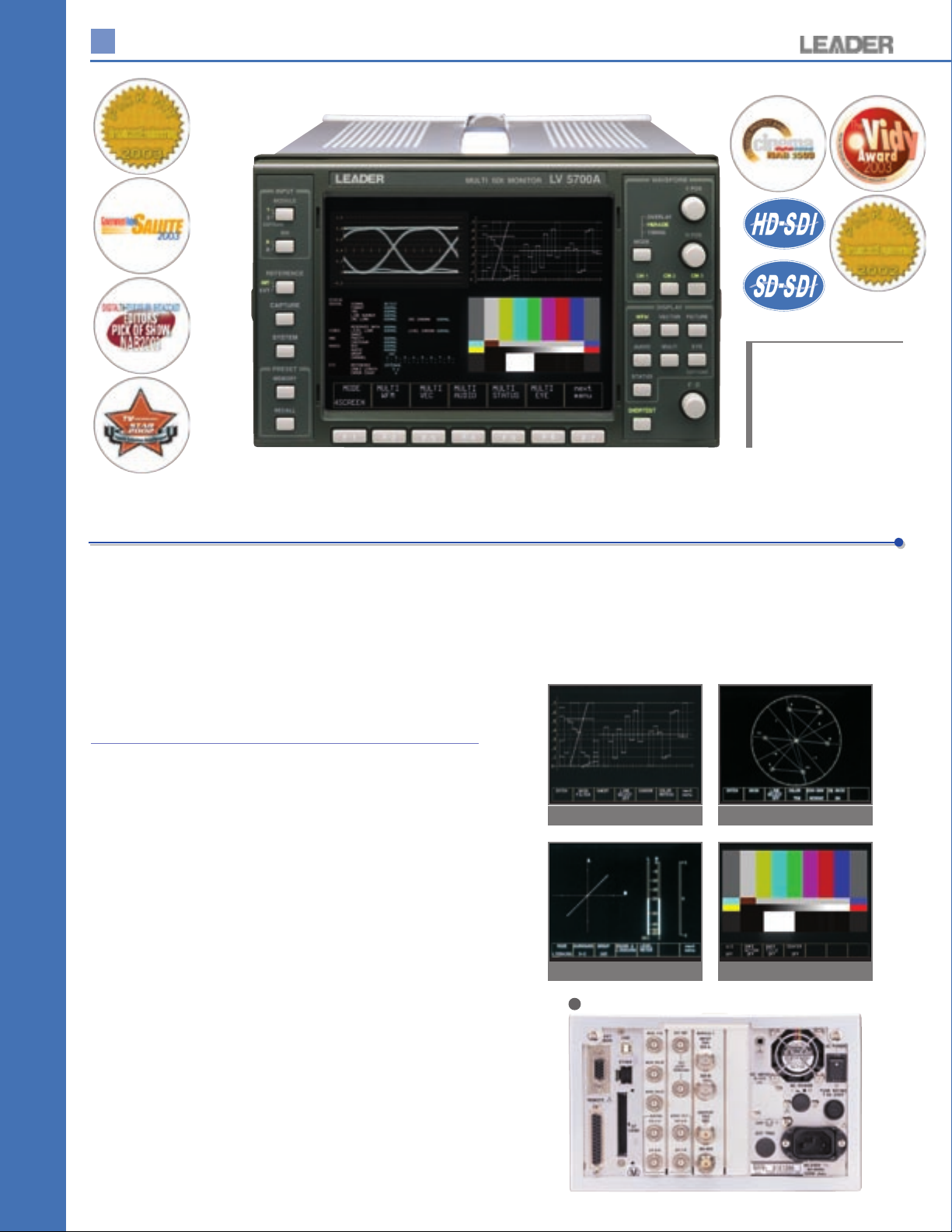
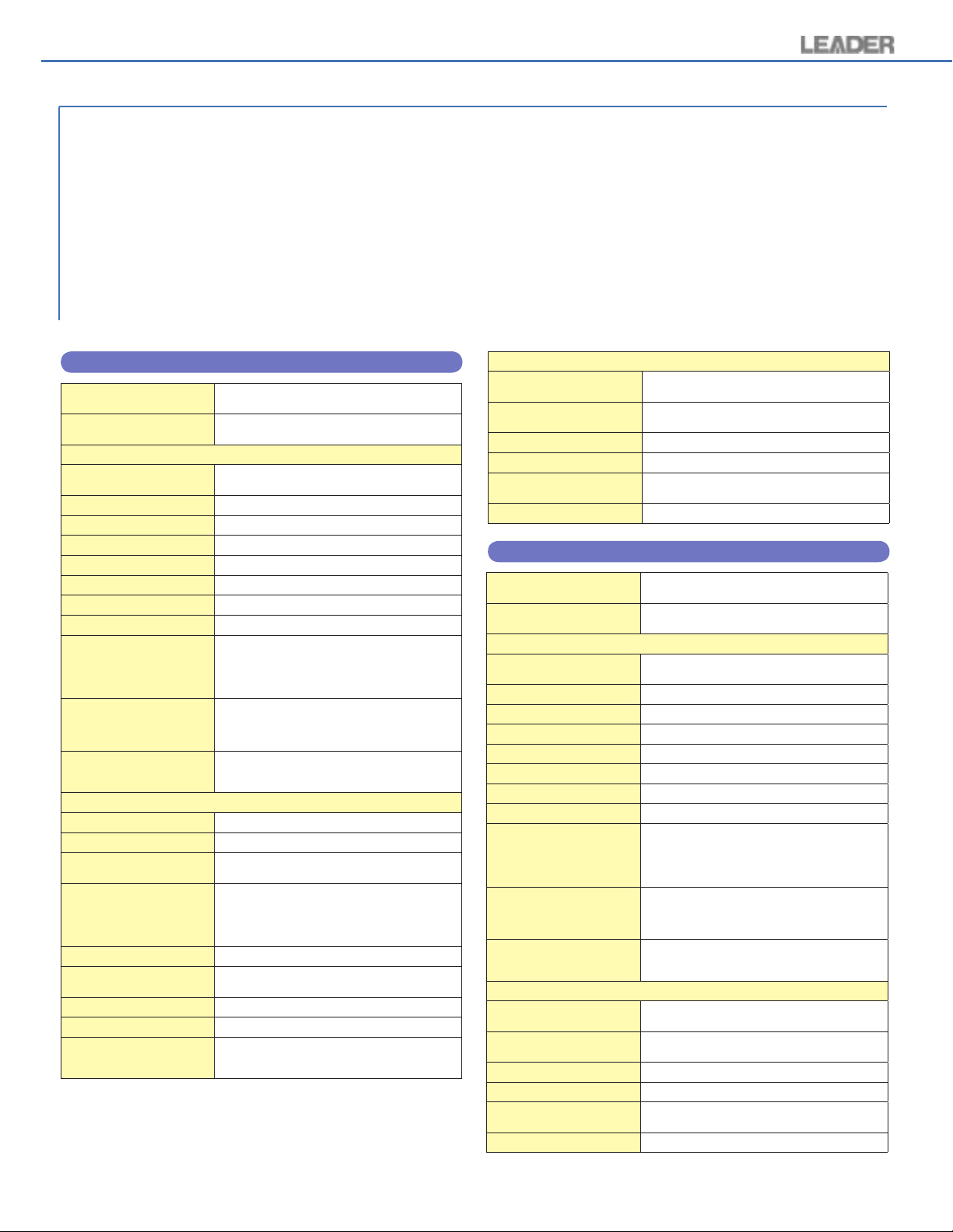
The LV 5700A is a multi SDI monitor with a unique tilting front
panel that incorporates an XGA TFT color LCD for HD-SDI
and SD-SDI signals.
The functions of waveform monitor, vectorscope, audio
lissajous, simple picture monitor, and digital protocol testing
are achieved within a single unit.
Signals are processed digitally enabling highly accurate
measurements. Extensive error detection and analysis
• Power Supply
The standard AC power supply allows for universal (90 V to 250 V)
operation.
DC power supply (12 V) enables use for digital acquisition in the field
(Option 71).
• Eye Pattern Display
Displays eye patterns and automatically measures physical characteristics
such as rise time, fall time, amplitude, and jitter. (Option 70)
functions are provided allowing SDI signals to be monitored
and logged.
FEATURES
•
Input
Receives either HD-SDI signals or SD-SDI signals.
Supports multiformat, automatic and manual setting of input formats.
• Display
Employs an LCD monitor with XGA resolution.
Waveform, vector, picture, embedded audio, and status display can be
placed side by side or in quad display on the monitor. Depending on the
selected combination, bowtie, data dump and optional AES/EBU digital
audio or eye pattern can also be displayed. Down converted pseudo
waveform and vectorscope modes represent NTSC or PAL modes.
Waveform and vector screens have user selectable graticule colors.
Furthermore, each display can be magnified.
•
Operation
The LV 5700A can be controlled through the panel and remotely controlled
through a computer via the Ethernet network. In addition, 100 custom
presets can be backed up to compact flash card and recalled from the
front panel or via the remote connectors on the rear panel.
•
Extensive Analysis Functions
The LV 5700A can be used as an analyzer to detect and log multiple
types of digital protocol transmission errors. Screens show gamut errors,
data dumps, EDH codes, analysis of voice control packets, equivalent
cable length and cable warning measurements, and so on. Frame
capture of any screen allows email of bmp files or logs for verification of
errors.
• Output
Provides HD-SDI/SD-SDI switching with a reclocked output as well as
analog picture monitor output and AES/EBU outputs.
In addition, an analog XGA output connector is provided enabling
information to be displayed on a large external monitor.
Waveform
Audio
LV 5700A REAR PANEL
Vector
Picture
6
Page 2
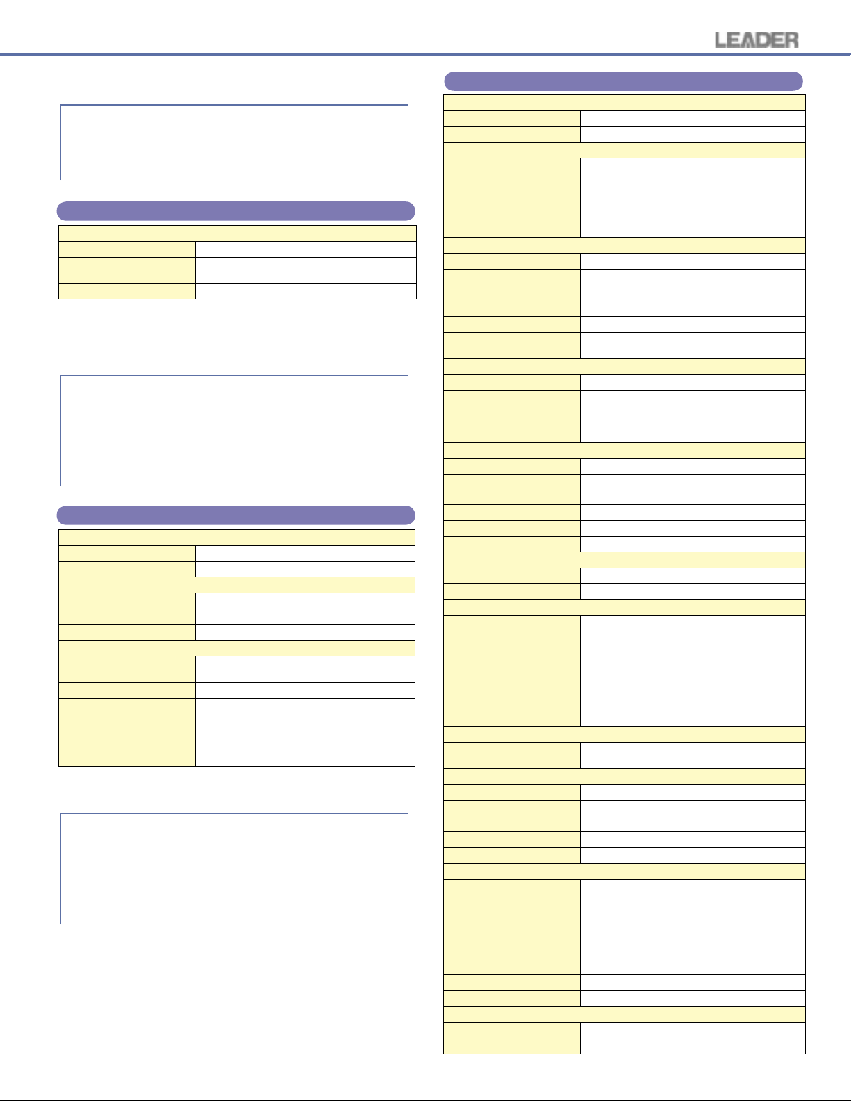
LV 5700A display
Picture
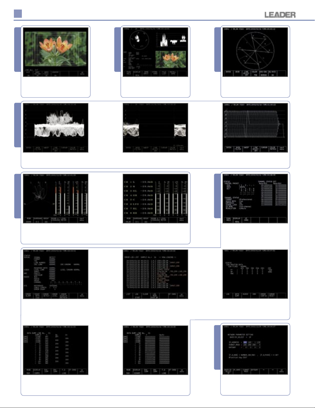
Nat ura l pic tur e (f l owe rs) w ith
selectable graticules in 16:9 or 4:3
modes for 4:3, safe action, safe title,
center cross and full line select strobe.
Waveform
Waveform monitor of YCBCR overlay
of natural picture.
Audio
Multi
M u l t i D i s p l ay o f w a v e f o rm,
nat ural pict ure , st atu s sc re en
and vec tor sco p e. M any oth er
combinations are available.
S p e c i al H o ri z on t a l S w e e p
m o d e o p t i m i z e s H b l a n k i n g
measurements for all formats.
Vector
Ve cto r di spl ay as 100 /75 % of
multiformat color bars with I and Q
axes displayed.
1080i/59.94 sweep of Y channel
with horizontal x20 magnification
applied.
Status
Audio displ ay o f 5.1 s ur round
sound and 8- Ch bargraphs with
VU ballistics. Bargraphs for 60 or
90 dB full scale peak are available.
Status screen shows alarms turned
on. About 20 protocols are checked
here including custom adjustable
alarms.
Audio Value makes it easy to see
exact reference or noise floor levels.
Note peak hold indication on 8-Ch
bargraphs.
Error log of error number, date,
time, module, input channel, INT/
EXT sy nc, signal detect ion and
error description with errors in red.
Audi o me t a data es s e nce for
control packet DID, sample rate,
active channels format, etc...
EDH error flags are broken out and
shown for SD as per RP 165.
System
1080i/59.94 Line 21 shows SAV hex
values, Y rise time of white bar 8
clock periods and 200h pedestals
for CBCR.
Line 21 SAV Y CB/CR with the data
dump in binary to check XYZ bits
for field, vertical, horizontal and
protection bit status.
Ethernet setting can be auto DHCP
or entered manually for IP address,
subnet mask and gateway.
7
Page 3
LV 5700A SPECIFICATIONS
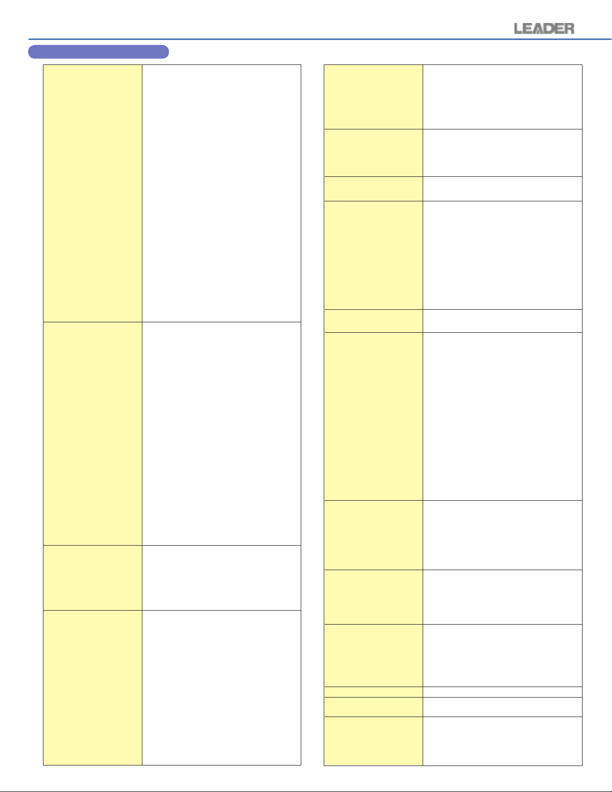
Video Format
HD-SDI
Video System
1
2
3
4
5
6
7
8
9
10
11
12
13
14
Standards Supported
HD-SDI Standard
Ancillary Data Standard
Embedded Audio Standard
SD-SDI
Video System
1
2
Standards Supported
SD-SDI Standard
Format Setting
Video System
Sampling Frequency
Input/Output Connector
HD-SDI Input
Input Connector
External Reference Input
Input Signal
Input Connector
XGA Output
Output Signal
Output Connector
HD-SDI Output
Output Connector
Analog Output
Output Signal
Output Connector
AES/EBU Output
Output Signal
Output Connector
Remote Connector
Function
Control Signal
Control Connector
Ethernet Connector
Function
Input/Output Connector
Display Format
Display Format
Dot Clock
Horizontal Frequency
Vertical Frequency
Display
Waveform Display
Waveform Operation
EAV-SAV Period
GBR Conversion
Sweep Magnification
Channel Assignment
Vertical Axis
Filter
Horizontal Axis
Operation Mode
Overlay
Parade
Timing
Display Format
Line Display
(Supported only on the LV 5700)
Ancillary Data Standard
Embedded Audio Standard
8
1920 x 1035 / 60i
1920 x 1035 / 59.94i
1920 x 1080 / 60i
1920 x 1080 / 59.94i
1920 x 1080 / 50i
1920 x 1080 / 30p
1920 x 1080 / 29.97p
1920 x 1080 / 25p
1920 x 1080 / 24p
1920 x 1080 / 23.98p
1920 x 1080 / 24sF
1920 x 1080 / 23.98sF
1280 x 720 / 60p
1280 x 720 / 59.94p
SMPTE 292M
SMPTE 291M
SMPTE 299M
525 / 59.94i
625 / 50i
SMPTE 259M
SMPTE 291M
SMPTE 272M
Select manual setting or automatic setting
HD: Auto switching between 74.25 MHz and
74.25/1.001 MHz
SD: 13.5 MHz
BNC connector 2 systems A and B, 75
Tri-level sync signal or NTSC/PAL black burst
BNC connector passive loop-through 1 system
2 connectors
XGA signal
D-sub 15 pin female
BNC connector 1 connector
Outputs the selected channel, 75
B
, PR or GBR
Y, P
BNC connector 1 system 3 connectors
CH1/2, CH3/4, CH5/6, CH7/8
Separated from embedded audio and output
Select 2 groups (8 ch) from 4 groups (16 ch)
BNC connector 4 connectors
Recalling of presets
TTL level (LOW active)
D-sub 25 pin female 1 connector
Remote control from an external computer and
monitoring of errors, etc.
10BASE-T/100BASE-TX 1 connector
XGA effective area 1024 x 768 dots
65 MHz or 64.935 MHz*
48.363 kHz or 48.315 kHz*
60 Hz or 59.94 Hz*
Automatically switch according to the input signal
(*
Displays waveform display, vector display, picture display,
and status display on a single screen side by side
Select show/hide
Select Y, P
Select x1 or x5
Select GBR order or RGB order during GBR
conversion display. YRGB display also supported
Flat, low-pass
Displays multiple waveforms overlaid
Displays waveforms side by side
Time difference between channels overlay
uses bowtie* signals
*Authorized by Tektronix, Inc.
Overlay: 1H, 2H
Parade: 1H, 2H, 3H
Timing: 2H
B
, PR or GBR conversion display
Ω
Line Magnification
Field Display
Field Magnification
Scale
Scale Display
Voltage Scale
% Scale
Vector Display
Sweep Magnification
Scale
EAV-SAV Period
I, Q Axes
Picture Display
HD Display
SD Display
Embedded Audio Display
Lissajous Display
Display Channel
Display Method
Sound Image Display
Display Channel
Peak Level Meter Display
Display Channel
Display Method
Channel
Ch Mapping
User Bit Display
Data Dump Display
Analysis Display
Data Dump Display
Display Format
Ω
)
Digital Signal Analysis
CRC Error
BCH Error
Checksum Error
Parity Error
TRS Error
EDH Error
Line Number
Gamut Error
Level Error
Audio Frequency
Format Detection
Audio Information Detection
External Sync Lock Detection
Equivalent Cable Length Measurement
Signal Detection
Line Selector
Operation Mode
Presets
Number of Presets
Preset Items
Recall Method
Cursor Measurement
Configuration
Amplitude Measurement
Time Measurement
Frequency Measurement
Environmental Conditions
Operating Temperature
Operating Humidity
Spec Guaranteed Temperature
Spec Guaranteed Humidity
Operating Environment
Operating Altitude
Pollution Degree
Power Requirements
Dimensions and Weight
Supplied Accessories
Select x1, x10, ACTIVE, or BLANK
Overlay: 1V, 2V
Parade: 1V, 2V, 3V
Select x1 or x20
0 V to 0.7 V, -0.3 V to 0.7 V
0 % to 100 %, -50 % to 100 %
Select from x1, x5, IQ-MAG.
Color bar switching type between 75 % and 100 %
Show/hide is synchronized with the waveform
display setting
Show/hide
Reduced display
Magnified display
Select from 2 ch or 8 ch display
Select X-Y or L-R
Select from 3-1 ch, 3-2 ch, and 3-2-2 ch displays
Simultaneous 8 ch display
Peak meter
Can be mapped arbitrarily from 1 ch to 8 ch
Displays 192 bits sequentially
Analyzes and Displays the user bit
Displayed separately by serial data sequence or
channel.
Detects video signal errors
Detects embedded audio errors
Detects ANC data errors
Detects ANC data errors
Detects TRS errors
Detects EDH errors
Detects line number errors
Detects level overrange of GBR video signals
Detects video level and reserved data errors
Detects continuity errors of embedded audio
Detects the SDI video signal format
Detects the presence or absence of embedded
audio on each channel
Detects the sampling frequency for each group
Displays voice control packets
Detects the synchronization relationship between the
external synchronization signal and the SDI signal
Measures the SDI signal level
Displays the cable length based on 800 mVp-p
signal source level
Detects the presence or absence of SDI signals
Interlocked type between waveform display,
vector display, and picture display
100 sets
All setup items
Through the front panel, remote connector, and Ethernet
Switch 8 points and 100 points for recalling
through the remote connector
Horizontal cursor: 2 lines (REF, ∆)
Vertical cursor: 2 lines (REF,
Measured in [%] and [V]
Displayed in [ms] and [µs]
Displays the frequency in which the time
between cursors is considered a cycle.
0 to +40 °C
≤
85 % RH (without condensation)
+10 to +30 °C
≤
85 % RH (without condensation)
Indoor use
Up to 2,000 m
2
90 to 250 VAC (48 Hz to 440 Hz) or 9 to 17 VDC (Option)
215 (W) x 133 (H) x 449 (D) mm 4.9 kg
8 1/2 (W) x 5 1/4 (H) x 17 11/16 (D) in., 10.8 lbs.
Instruction manual
Power cord
Cover/Inlet stopper
Screws for rack mounting (inch specification)
25-pin D-sub connector
25-pin D-sub connector cover
........................................................
, groups 1 x 2 or 3 x 4
)
∆
............................................
...........................................
....................................
..........................
.........
.
1
1
1
2
1
1
Page 4
LV 5700A Multi-SDI Monitor Available Options
Our industry is changing faster than our customers can
adopt to t he new techn olo gy; syst ems , form ats an d
performance demands on the production, post production
and distribution channels of the pro-video industry have
created the necessity for a monitoring instrument that is not
only flexible but also highly configurable and adoptable to
future format and system changes. The Leader LV 5700A
Multi-SDI monitor was designed to provide the utmost in
system configuration flexibility and allows for future options
to be added in order to ensure our customers' investment
remains useful for years to come.
The instrument handles HD-SDI and SD-SDI inputs in its
standard configuration (see pages 6 to 7 for standard
configuration specs and details) and can be upgraded
to handle a variety of inputs depending on your system's
needs. For example, our latest option introduction (OP77
Dual Link) allows our LV 5700A owners to upgrade their
instrument to include the new Dual Link format without
havi ng to pu rch a se a ne w i nstr umen t . U p comi n g
introductions (NAB2005) will include an MPEG decode and
monitoring function for the LV 5700A allowing LV 5700A
users the ability to decode and monitor MPEG streams. Our
LV 5700A provides the flexible platform needed to
satisfy the variety of formats and systems available in our
industry today; but, it is Leader's wide selection of options
that make the LV 5700A an excellent investment not only for
today but for years to come.
Two (2) expansion slots are available for the LV 5700A and
the available options are listed below :
LV 5700A OP70 (LV 57SER70) : HD/SD Eye Pattern Module; Takes 2 Slots
LV 5700A OP71 (LV 57SER71) : DC Operation Module for LV 5700A (no slots
LV 5700A OP72 (LV 57SER72) : Additional HD/SD-SDI Input Module For The LV
LV 5700A OP73A
LV 5700A OP74 (LV 57SER74) : Analog Audio Monitor Module
LV 5700A OP75 (LV 57SER75) : AES/EBU Digital Audio Module (8 Channels)
LV 5700A OP76 (LV 57SER76) : HD/SD Eye Pattern Module; Takes 2 Slots
LV 5700A OP77 (LV 57SER77) : Dual Link Module
LV 5700A MPEG Card : MPEG Stream Module; Takes 1 Slot
(LV 57SER73A)
required)
5700A (adds 2 more SDI inputs for a total of 4)
: NTSC/PAL Composite Analog Input Module
For LV 5700A
In the next few pages (pages 10 - 13) you will find a brief
description and specifications for our LV 5700A options. For
additional information, please call us at 1 (800) 645-5104 or
e-mail us at [email protected]
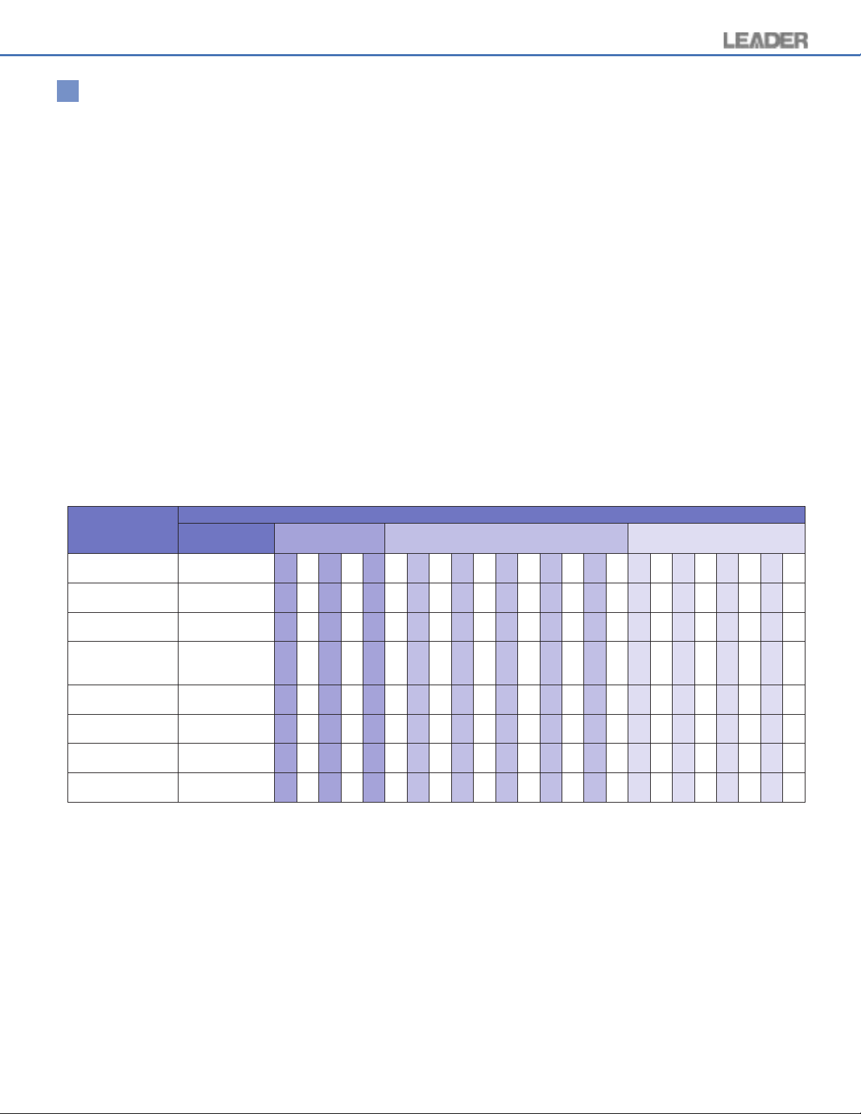
Selection Guide (Combination Conditions)
Product Name
HD/SD EYE Pattern *1Option 70
DC Operation
Additional HD/SD-
SDI Input
NTSC/PAL
Composite Analog
Input
Analog Audio
Monitor
AES/EBU Digital
Audio
HD/SD EYE Pattern *2Option 76
Dual Link
Option Name
Model Number
LV 57SER70
Option 71
LV 57SER71
Option 72
LV 57SER72
Option 73A
LV 57SER73A
Option 74
LV 57SER74
Option 75
LV 57SER75
LV 57SER76
Option 77
LV 57SER77
3 Options Selection 2 Options Selection 1 Option Selection
70 70
71 71 71 71 71 71 71 71 71 71 71 71
72 72 72 72
73A 73A 73 73A
74 74 74 74
75 75 75 75
76 76 76 76 76 76 76 76 76 76 76 76 76
77 77 77
* 1: Phase Detection is used for measuring the jitter value. Features include EYE Pattern, Jitter Display and Histogram.
* 2: Eye Pattern is used for measuring the jitter value. Features include EYE pattern only.
9
Page 5
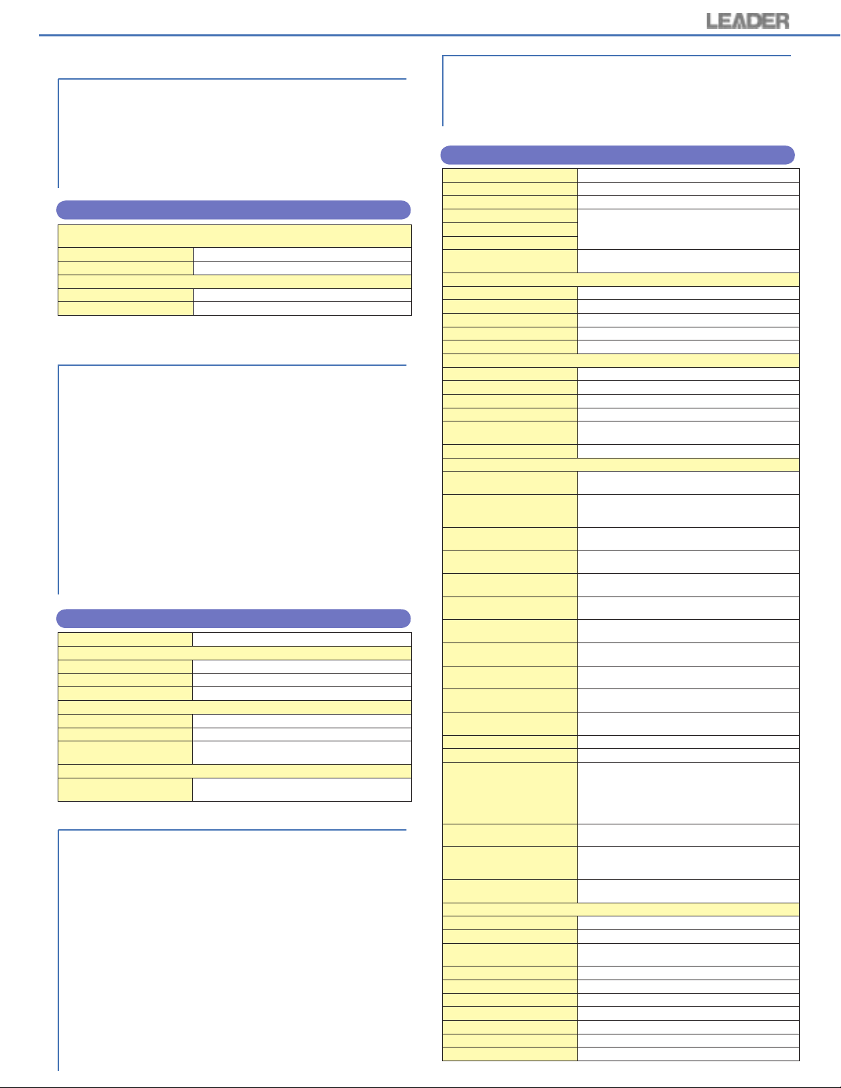
HD/SD Eye Pattern Module (OP70 & OP76)
Le ad er provides tw o different o ptions for Eye Pattern
monitoring for the LV 5700A; Option 70 and Option 76.
Option 70 represents our full-featured Eye Pattern monitoring
solution and takes up 2 slots in the LV 5700A while our
Option 76 (reduced feature set) only occupies one slot in the
LV 5700A leaving the other slot open for other options and
upgrades.
Our OP70 has selectable display modes that encompass
eye pattern views, jitter measurements (both manual and
automatic) and a histogram with jitter. The OP70 uses both
equivalent sampling and phase detection methods in order
to provide the eye pattern measurements.
Our OP76 includes all of the measurement features of
the OP70 except for the histogram function. Eye pattern
measurements are made using the equivalent sampling
technique.
Both OP70 and OP76 provide eye pattern displays, cursor
and automatic measurement modes. Jitter is characterized
with automatic readouts of key parameter measurements for
rise time, fall time, amplitude and jitter. Five high pass filters
are selectable from 10Hz to 100KHz. Lower edge filters
for timing jitter (10Hz) or alignment jitter (100KHz) measure
jitter components up to one tenth of the clock frequency. An
external rear panel clock input allows for making optimum,
absolute jitter measurements without adding PLL reclocking
artifacts while a rear panel output (OP70 only) allows to
monitor demodulated jitter components on an external
spectrum analyzer.
OP70 HD/SD EYE PATTERN SPECIFICATIONS
Standard Supported
Data Rate
Eye Pattern Display
Display
Method
Frequency Range
Amplitude Accuracy
Time Axis
Time Axis Accuracy
Jitter Filter
Cursor Measurement
Automatic Measurement
Jitter Display
Display
Method
Amplitude Accuracy
Jitter Filter
Cursor Measurement
Automatic Measurement
Jitter Output
Output Connector
Output Level
10
HD SMPTE292M
SD SMPTE259M
HD 1.485 Gbps or 1.485/1.001 Gbps
SD 270 Mbps
Displays the SDI input waveform before
equalizing
Equivalent time sampling method
10 MHz to 2.5 GHz within +1, -3 dB
Within 800 mV ± 5 % for 800 mV input
2 waveform display 100 ps/div
4 waveform display 200 ps/div
16 waveform display 800 ps/div
Within ± 3 %
10 Hz HPF
100 Hz HPF
1 kHz HPF
10 kHz HPF
100 kHz HPF
Amplitude measurement using the Y cursor
Time and jitter measurements using the X
cursor Rise time and fall time measurements
using the Tr and Tf cursors
Measures and displays the amplitude, the jitter,
the rise time, and the fall time from the eye
pattern. Can be turned on/off
Displays the jitter component of the SDI input
Phase detection method
Within ± 10 % when applying 10 KHz 1 UI jitter
(using 100 Hz filter)
10 Hz HPF
100 Hz HPF
1 kHz HPF
10 kHz HPF
100 kHz HPF
Jitter measurement using cursors
Displays the amount of jitter in time (sec) and
unit interval (Ulp-p)
75 Ω BNC connector, 1 output
Within 200 mV/UI ± 20 % (at 10 kHz jitter
frequency and 75
*Jitter output is enabled in jitter display mode.
Ω
termination)
EXT REF Input for Eye Patterns
Standard
Data Rate
Input Connector
Input Level
Input Format
Maximum Input Voltage
HD SMPTE292M
SD SMPTE259M
HD 1.485 Gbps or 1.485/1.001 Gbps
SD 270 Mbps
Ω
75
BNC connector, 1 input
Signal source amplitude Within 0.8 Vp-p ±10 %
HD SMPTE292M
SD SMPTE259M
± 2 V (DC + Peak AC)
OP76 HD/SD EYE PATTERN SPECIFICATIONS
Standard Supported
Data Rate
Eye Pattern Display
Display
Method
Frequency Range
Amplitude Accuracy
Time Axis
Time Axis Accuracy
Jitter Filter
Cursor Measurement
Automatic Measurement
EXT REF Input for Eye Patterns
Standard
Data Rate
Input Connector
Input Level
Input Format
Maximum Input Voltage
Note: Option 70: Phase detection method is used for jitter measurement and
Option 76: Equivalent time sampling method is used for jitter measurement
functions are eye pattern, jitter display and histogram
and function is eye pattern
HD SMPTE292M
SD SMPTE259M
HD 1.485 Gbps or 1.485/1.001 Gbps
SD 270 Mbps
Displays the SDI input waveform before
equalizing
Equivalent time sampling method
10 MHz to 2.5 GHz within +1, -3 dB
Within 800 mV ± 5 % for 800 mV input
2 waveform display 100 ps/div
4 waveform display 200 ps/div
16 waveform display 800 ps/div
Within ± 3 %
10 Hz HPF
100 Hz HPF
1 kHz HPF
10 kHz HPF
100 kHz HPF
Amplitude measurement using the Y cursor
Time and jitter measurements using the X cursor
Rise time and fall time measurements using the Tr
and Tf cursors
Measures and displays the amplitude, the jitter,
the rise time, and the fall time from the eye
pattern. Can be turned on/off
HD SMPTE292M
SD SMPTE259M
HD 1.485 Gbps or 1.485/1.001 Gbps
SD 270 Mbps
Ω
75
BNC connector, 1 input
Signal source amplitude within 0.8 Vp-p ±10 %
HD SMPTE292M
SD SMPTE259M
± 2 V (DC + Peak AC)
Page 6
DC Operation Module (OP71)
Ideal for mobile and field acquisition applications, this
option allows the LV 5700A to operate from a 12 Vdc
source. A wide range DC supply may be used (9 Vdc 17 Vdc). This option can only be installed at the time of
purchase.
OP71 DC OPERATION SPECIFICATIONS
DC Operation
Input Voltage Range
Input Terminal
Fuse
DC 9V ~ 17V
XLR Connector
(Pin 1 is GND and Pin 4 is power terminal)
Time lag 10A
Additional HD/SD-SDI Input Module (OP72)
In applications that require more than 2 monitoring inputs,
the OP72 adds another 2 HD-SDI and SD-SDI inputs for a
total of 4 monitoring SD&HD - SDI inputs. Specifications
for this option are identical to the specifications of the
LV 5700A standard inputs (see page 12 for specification
details). All of the monitoring/measurement features and
capabilities of the LV 5700A apply to the OP72 inputs as
well.
OP72 ADDITIONAL SDI INPUT SPECIFICATIONS
Standards Supported
HD
SD
SDI Input
Input Connector
Input Impedance
Input Return Loss
SDI Output
Output Connector
Output Impedance
SD-SDI Dedicated Output
Connector
Weight
Maximum Power
Consumption
NTSC/PAL Composite Analog Input Module (OP73A)
Ideal for broadcast and field acquisition professionals, the
option 73A adds expansion capabilities to accommodate
analog NTSC/PAL composite inputs. Two composite inputs
(auto-sensing) are provided and the selected input is fed to
a monitoring output. Monitoring functions include waveform,
vector and picture displays. SCH measurement is also
provided for both NTSC and PAL and full line selection
capabilities allow monitoring on a line-by-line basis.
SMPTE 274M, 292M, 240M, 296M, RP211
SMPTE 259M
BNC connector, 2 systems (A/B)
Ω
75
15 dB above, 5 MHz serial clock frequency
BNC connector, 1 connector, Selected channel
output
Ω
75
BNC connector, 1 connector, Active only when
selected signal is SD-SDI signal
5.0 kg
120 W
OP73A NTSC/PAL COMPOSITE ANALOG SPECIFICATIONS
Standards Supported
NTSC
PAL
Input
Composite Video
Input Connector
Input Impedance
Input Return Loss
Maximum Input Voltage
Output
Composite Video
Output Signal
Output Connector
Output Impedance
Output Amplitude
Frequency
Characteristics
Display
WAVEFORM
VECTOR
PICTURE
Waveform Display Section
Vertical Axis
Sensitivity
Gain
Variable Gain
Amplitude Accuracy
Frequency Characteristics
Composite Signal
Step Response (for 1V full scale, flat, 2T pulse, and 2T bar)
Overshoot
Preshoot
Ringing
Pulse/Bar Ratio
Vertical Tilt
Filter
DC Restorer
Horizontal Axis
Operation Mode
Display Format
Line Display
Line Magnification
Field Display Overlay
Field Magnification
Time Base Accuracy
Vectorscope Display Section
Sensitivity
Setup
Gain
Variable Gain
Phase Accuracy
Amplitude Accuracy
Phase Adjustment Range
IQ Axis
SCH Measurement Section
Accuracy
Color Frame Area
NTSC-M, SMPTE 170M
PAL-B, G, H, I, ITU-R BT.470
Select A or B
BNC connector
Ω
75
≥
30 dB (up to 6 MHz)
± 5 V (DC + Peak AC)
Active
BNC connector, 1 system 1 connector
Ω
75
≤
1 Vp-p ± 5%
25 Hz to 5 MHz within ± 5%
5 MHz to 5.6 MHz within +5% to -10%
Waveform display
Vectorscope display
Picture display
* 2 screens mode, 4 screens mode, audio
display, and status display are not available.
V Scale 1 Vp-p (-0.3 V to 0.7 V)
IRE Scale 1 Vp-p (-40 IRE to 100 IRE)
x1, x5 Selectable
x 0.1 or less to x5 or more
≤
1%
25 Hz to 5 MHz within 2%
5 MHz to 5.6 MHz within +3% to -5%
± 2%
± 1%
± 2%
± 1%
± 1%
Luminance filter
Clamp to the back porch (fixed)
Overlay
Displays only one single waveform
Overlay 1H or 2H
Select x1 or x10
1V or 2V
Select x1 or x20
± 1%
Select 75% or 100% (ref color bar pattern)
Select 0% or 7.5%
Select x1, x5 or IQ-MAG
x0.1 or less to x10 or more
± 2°
± 3%
360°
Select show or hide
± 5° (room temperature 25°C)
± 60°
11
Page 7
Analog Audio Monitor Module (OP74)
Option 74 decodes any pair of embedded AES/EBU channels
(must be in the same group of 8) to analog audio and provides
a mini-speaker and headphone output for audio monitoring.
Front panel menu selection allows for headphone monitoring
of selected channels. This option is not needed if the LV
5700A is equipped with an Option 75 (External AES/EBU
Inputs for the LV 5700A). Option 75 includes the functions of
Option 74.
OP74 ANALOG AUDIO MONITOR SPECIFICATIONS
Analog Audio Output
Headphone Audio Output
Output Channels
Output Connector
Built-In Loudspeaker
Loudspeaker Size
Loudspeaker Number
Note: Ear phone output terminal is connected to 32Ω headphone for volume
adjustment
1 (monaural)
Miniature jack (Stereo type)
1 (monaural)
36 ø
AES/EBU Digital Audio Module (8 Channels) (OP75)
The LV 5700A Multi-SDI monitor is provided with audio
monitoring, measurement and data analysis capabilities for
embedded AES/EBU monitoring (audio is disembedded
and output via 4 BNC connectors; 8 channels, as standard).
Facilities using separate (non-embedded) AES/EBU audio
will need to use the OP75 External AES/EBU Inputs option
in order to monitor external AES/EBU. All of the embedded
audio measurement, monitoring and analysis abilities of the
LV 5700A are also available for monitoring external AES/
EBU using the OP75.
Option 75 adds monitoring and display for 8-channels of
AES/EBU digital audio inputs. Surround sound image,
lissajous, bar graphs and digital levels are displayed. An
on-screen display indicates if the embedded audio is
synchronous with the external AES/EBU input audio and
shows lock/unlock or no signal. A speaker is also included
to allow monitoring of the selected channel.
OP75 AES/EBU DIGITAL AUDIO SPECIFICATIONS
Format Supported
AES/EBU Digital Audio Input
Input Channels
Input Connector
Input Impedance
Headphone Audio Output
Output Channels
Output Connector
Output Format
Built-In Loudspeaker
Output Format
Dual Link Module (OP77)
First to introduce and implement a Dual Link monitoring
solution for the production/acquisition and post production
markets, Leader has been providing Dual Link solutions to
the emerging HDTV based feature film production since
2003. Our most recent introduction, our OP77 Dual Link
option, is a new SDI input module that adds compliance
to HD-SDI Dual Link formats as per SMPTE 372M. OP77
provi des sep arate , de dicated A and B inpu ts ( wit h
reclocked outp uts) for Dual Link monitoring on the LV
5700A; leaving the standard built-in HD-SDI inputs available
for traditional SDI monitoring.
Waveform, vector and s ta tu s/ da ta dump screens are
available for Dual Link monitoring and they represent a
combination of BOTH links; all of the facilities of the LV
5700A can be used to monitor Dual Link systems. A picture
12
display as well as embedded audio monitoring is also
provided (Link A only).
AES/EBU format 48 kHz
4 BNC, 8 channels (CH 1/2, 3/4, 5/6, 7/8)
BNC Connector
Ω
75
1 terminal
Miniature jack (stereo type)
Stereo. Selects the channel from the menu to set
up L, R channel
Mono. Outputs selected L channel sound to
speaker output.
With the addition of OP77 Dual Link option, the LV 5700A
becomes the ideal monitoring tool for Dual Link applications.
The unit also retains all of its HD-SDI monitoring capabilities
and adding this option does not change the standard
operation of the instrument.
OP77 DUAL LINK SPECIFICATIONS
Standard Supported
Signal Format
4:2:2 (Y’ C
4:4:4 (R’ G’ B’) / *10bit
4:4:4 (R’ G’ B’) / *12bit
4:2:2 (Y’ C
Differential Phase Between
A/B Link
Input/Output Connectors
HD-SDI Input
Input Connector
Input Impedance
Input Return Loss
Max Input Voltage
SDI Output
Output Connector
Output Impedance
Output Voltage
Output Return Loss
Signal Format
Marker
Status Display
Signal Detection
Format Detection
TRS Error
Line Number Error
CRC Error
Reserved Error
Level Error
Gamut Error
Composite Gamut
BCH Error
Audio Continuity
Audio Information
External Sync
Cable Length
Phase Difference
Phase Shift Error
Payload ID Display
Environmental Specifications
Operating Temperature
Operating Humidity
Spec-Guaranteed
Temperature
Spec-Guaranteed Humidity
Operating Environment
Operating Altitude
Overvoltage Category
Pollution Degree
Power Requirements
Accessories
B
’ CR’) / *10bit
B
’ CR’) / *12bit
SMPTE 372M
Frame / field rates
60, 60/1.001, 50 p
60, 60/1.001, 50i
30, 30/1.001, 25, 24, 24/1.001 p, PsF
Automatically compensated and displayed up to
100 clocks (approx. 1.4us)
BNC connector, 2 connectors (A Link, B Link)
Ω
75
≥
15dB, 5MHz ~ Serial clock frequency
±2V (DC + peak AC)
BNC connector, 2 connectors (A Link, B Link)
Ω
75
800 mVp-p ± 10%
≥
15dB, 5MHz ~ Serial clock frequency
Output as input signal or output as YCbCr
converted from RGB
Luminance offset is added to selected line
HD-SDI signal detection of both A/B Links at the
same time
HD-SDI signal format detect, Error display
when A/B Link formats do not match or are
unrecognized formats.
TRS error detection of both A/B Links at the same
time
Line number error detection of both A/B Links at
the same time
HD-SDI transmission error detection of both A/B
Links at the same time
Reserved error detection of both A/B Links at the
same time
Video level error detection of both A/B Links at
the same time
Gamut error detection (does not detect gamut
during GBR 4:4:4 input)
Monitors level error of component to composite
conversion errors
Embedded audio transmission error detection of
both A/B Links at the same time
Continuity error detection of the selected audio
packets
Detects the presence of each audio channel
Detection of external sync signal
SDI signal level measurement
Display LS-5CFB coaxial cable length at signal
source level 800 mVp-p by calculation.
Display as <5m, 5m, …, 125m, > 130m.
Resolution, 5m per step
Accuracy, ±20m (when using LS-5CFB)
Display phase difference of A/B Link in time unit
display
Displays error when the phase shift is over the
setting limit. Synchronized or unsynchronized of
A/B Link can be checked.
SMPTE 352M compliant for payload ID packet
display
0 to 40 °C
≤
85% RH (without condensation)
10 to 30 °C
≤
85% RH (without condensation)
Indoor use
Up to 2,000m
II
2
Supplied by LV 5700A series mainframe
Instruction manual 1
Page 8
MPEG Stream Module
During NAB 2005 we will be introducing another exciting
and useful option for the LV5700A; our MPEG input card.
This new option will allow you to input MPEG streams to
the LV 5700A (up to 60 Mbits). The card will decode the
selected program and will pass the base band video to the
LV 5700A; in this manner, video professionals can monitor
key parameters of the MPEG stream as well as monitor
and measure the baseband video and view waveform,
vector, picture and audio analysis screens. More details
will be available at NAB2005 and we expect delivery for
this option shortly after NAB 2005.
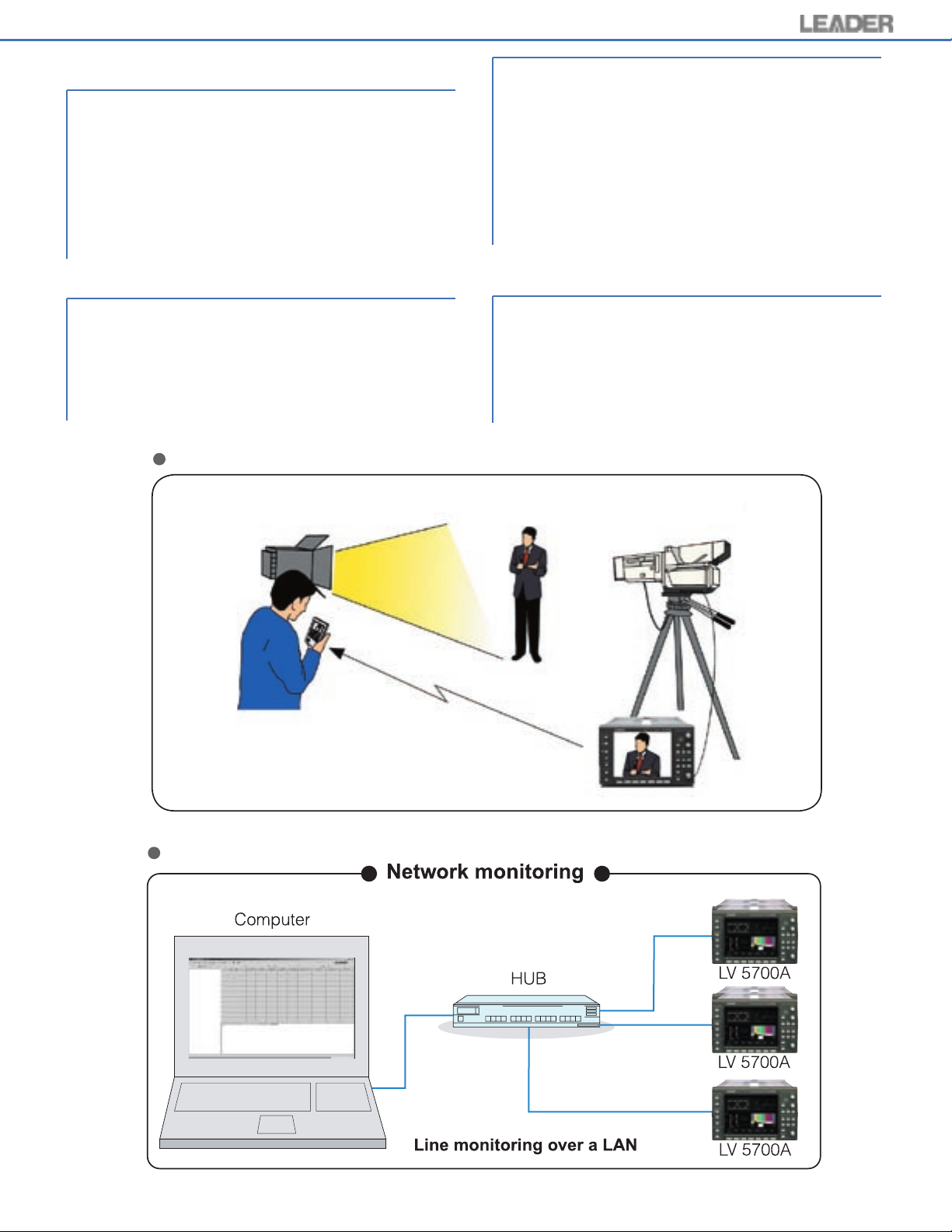
of the LV 5700A Ethernet output, to a wireless access
point router (802.11 b) and then to a WiFi enabled Pocket
PC 2002 PDA. Tapping an arbitrar y part of the picture
displayed on the browser screen of the Pocket PC, and
then tapping zoom will show a magnified screen area with
YRGB values. The user can also preset custom separate
upper and lower YRGB alarm levels. The engineer can
obtain lig hting me asurement s a nd improve li ghting
adjustments while standing next to the lighting apparatus.
Monitoring YRGB levels with custom alarms, expedites
lighting adjustments to legal digital values saving reshoots,
which is time and money.
Lighting Monitor (FS 3018)
Option FS 3018 the Lighting Monitor, garnered 5 Pick Hit
Awards at NAB 2003. Firmware is added to the LV 5700A
enabling extended use of network functions.
Basically, it remotely views and judges what the digital
camera, monitored by the LV 5700A is seeing. It expedites
the process of checking lighting conditions during digital
acquisition and monitoring on the set. The Lighting Monitor
transmits any quadrant of the multiple-display screen
Lighting Monitor (FS 3018)
Remote Monitoring Software (FS 3019)
Option FS 3019 application software allows PC remote
contr ol and mon ito ring o f up to 50 LV 5700 A Multi
SDI Monitors over a local area network. Error logs are
automatically created and stored to facilitate proper record
keeping. Users can access and remote control the LV
5700A from personal computers equipped with a dial-up
function over the Internet or leased lines enabling secure
and reliable monitoring of remote broadcast stations.
Remote Monitoring Software (FS 3019)
13
 Loading...