

LT1610A/LT1611/LT1612A PROGRAMMABLE VIDEO GENERATOR (Terminal Mode)
INSTRUCTION MANUAL
For Rom version 1.62 and above.
LEADER ELECTRONICS CORP.
TABLE OF CONTENTS
| 1. DESCRIPTION | 1-1 |
|---|---|
| 2. SPECIFICATIONS | 2-1 |
| 2.1 Interface Specifications | 2-1 |
| 2.2 RS-232C Connector Pin Assignments | 2-2 |
| 2.3 Connecting AT Compatible Personal Computer | 2-2 |
| 3. TRANSMISSION DATA | 3-1 |
| 3.1 Transmission Control Characters | 3-1 |
| 4. STARTING/ENDING TERMINAL MODE | 4-1 |
| 4.1 Description of Terminal Mode | 4-1 |
| 4.2 Starting RS-232C Terminal Mode | 4-2 |
| 4.3 Ending RS-232C Terminal Mode | 4-3 |
| 5. CONSTRICTION OF TERMINAL COMMAND | 5-1 |
| 6. NOTES ON USING TERMINAL COMMANDS | 6-1 |
| 7. SETTING COMMANDS | 7-1 |
| 7.1 Graphic Plane Clear Command [ 02 2E 0C 03 ] | 7-1 |
| 7.2 Delay Command [ 02 2E 0F 03 ] (Factory Use Only) | 7-2 |
| 7.3 Direct Address Command [ 02 2E 21 03 ] | 7-3 |
| 7.4 ROM/RAM Selection Command [ 02 2E 22 03 ] | 7-4 |
| 7.5 BEGIN/END Address Setting Command [ 02 2E 21 03 ] | 7-5 |
| 7.6 Quick-Setting Command [ 02 2E 24 03 ] | 7-6 |
| 7.7 Comment Positioning Command [ 02 2E 30 03 ] | 7-7 |
| 7.8 Comment Character Change Command [ 02 2E 31 03 ] | 7-9 |
| 7.9 Circle Drawing Command [ 02 2E 60 03 ] | 7-10 |
| 7.10 Line Drawing Command [ 02 2E 61 03 ] | 7-11 |
| 7.11 Dot Drawing Command [ 02 2E 62 03 ] | 7-12 |
| 7.12 Fill-in of Circle Drawing Command [ 02 2E 63 03 ] | 7-13 |
| 7.13 Ellipse Drawing Command [ 02 2E 64 03 ] | |
| 7.14 One Character Drawing Command [ 02 2E 65 03 ] | |
| 7.15 All Character Drawing Command [ 02 2E 66 03 ] | 7 10 |
| 7.17 Split Color-Gray Window Drawing Command | |
| 7-19 | |
| 7.18 Single-Color Color-Gray Window Drawing Command | 10 |
| [ 02 2E 81 03 ] | 7-21 |
|
11-1
11-1 11-2 11-3 |
|---|---|
| 11.4 HS Output-4 (DIP SW2-3: ON, HS Output Sel: HS) | |
| 12. LIST OF SETTING COMMANDS | 12-1 |
| 13. DATA RECEPTION COMMAND LIST | 13-1 |
| 14. KEY CODE LIST | 14-1 |
| 15. SETTABLE SYNC RANGE |
2. SPECIFICATIONS
2.1 Interface Specifications
| Communication System | Full duplex |
|---|---|
| RTS/CTS control |
Baud Rate
Selectable with DIP switches (DIP SW2-1, 2) located in the user ROM compartment.
| SW2-2 | SW2-1 | 2 700 |
|---|---|---|
| OFF | OFF | 9600 bps |
| OFF | ON | 19200 bps |
| ON | OFF | 19200 bps |
| ON | ON | 38400 bps |
| * Fither 19200 bos can be used |
Input/Output Level
EIA-RS-232C
Data Format
| Start Bit | 1 bit | |
|---|---|---|
| Data Bit | 8 bits | |
| Stop Bit | 1 bit | |
| Parity Check | None | |
Error Control System
Not available
3.1 Transmission Control Characters
Table 1 shows transfer control characters for remote controlling the LT 1610A/ 1611/1612A with a personal computer.
| Table 1 | e, key operatio |
|---|---|
| Character | HEX Code |
| ENQ (Enquire) | 05h |
| EOT (End of transmission) | 04h |
| ACK (Acknowledge) | 06h |
| NAK (Negative acknowledge) | 15h |
| STX (Start of text) | 02h |
| ETX (End of text) | 03h |
3-1
4.2 Starting RS-232C Terminal Mode
To start the RS-232C terminal mode of the LT 1610A/1611/1612A with a personal computer, transmit 05h (ENQ) to the LT 1610A/1611/1612A. When the terminal mode is accepted, 06h (ACK) is returned.
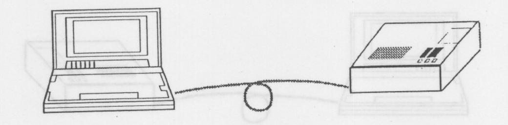
Personal computer

Requests to start RS-232C remote mode. Transmits 05h (ENQ).
Accepts to start RS-232C remote mode Returns 06h (ACK).
Terminal mode is enabled.
| , and a second | |
|---|---|
| mmå. |
LT 1610A/1611/1612A, LED r: Terminal mode 18: Address number
- * If the terminal mode start command is not executed, the terminal command is not accepted. In this case, "E10" is displayed on the LT 1610A/1611/1612A LED.
- * When LT 1610A/1611/1612A is busy, transmitted data is only stored in the reception buffer. After busy status is canceled, data stored in the buffer is executed, then 06h (ACK) code is returned.
5. CONSTRICTION OF TERMINAL COMMAND
This section describes construction of the terminal command. The terminal mode is executed by transmitting 8-bit data in serial format via the RS-232C interface.
Before executing the command, the system should be set to terminal mode. Refer to Section 4.2,."Starting RS-232C Terminal Mode" for detail.
Win → LT 16XX: Data described below are transmitted from the personal computer equipped with BS-232C serial port to the LT 16XX
- 02: STX (Start of text) Fixed data attached to first character of the terminal command.
- 2E: Terminal command, group ID Fixed data attached to second character of the terminal command.
- CC: Terminal command, individual ID Attached to third character of the terminal command.
- P1 to Pn: Command parameter
Parameters required for each terminal command Parameter data length depends on the individual ID
03: ETX (End of text) Fixed data attached to end of the terminal command.
Data "06h" is transmitted from the LT 16XX to the personal computer equipped with RS-232C serial port.
7. SETTING COMMANDS
7.1 Graphic Plane Clear Command [ 02 2E 0C 03 ]
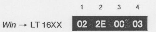
Win ← LT 16XX 106h (ACK)
0C: Graphic plane clear command No parameter, command only
Function: This command is used to clear one of the graphic planes (*) displayed.
Note: There is no parameter to be set.
This command is effective when the quick pattern or quick address is set on. However, when the quick-registered plane is displayed, it is cleared by executing this command. Set quick mode again to display the plane.
This command only clears one of graphic planes displayed up front. Therefore, this command is ineffective for such patterns displayed by using eight graphic planes as natural-color patterns and gray scale. Patterns (e.g., color bars) drawn without a graphic plane cannot be cleared.
(*) Graphic plane:
Displays pattern numbers (i.e., 00h, 01h, 10h, 11h, 40h - 74h). The level can be varied with the "GR Level" of the "Signal" tab in the "Timing set" program. Lines, characters, and circles of special pattern A0h are drawn by using a graphic plane.
7.3 Direct Address Command [ 02 2E 21 - - 03 ]
Win LT 16XX 02 2E 21 MM XX 03
21: Direct address command
MM: Address mode 00h: ROM mode 01h: RAM mode XX: Address data (00 - 63h)
- Function: This command is used to directly set program addresses 00 through 63h (99 in decimal number) and ROM/RAM mode in binary format. Addresses exceeding "Begin" and "End" can be accepted.
- Note: When address data exceeds 99, "E10" is displayed on the LED, and the previous pattern is drawn. When the mode data is other than "00h" or "01h," "E10" is displayed on
the LED, and the previous pattern is displayed.
This setting remains effective until power is turned off. When the terminal mode ends and LT 16XX is operated without remote controller LT 1610-01 (sold separately), this mode depends on the setting of "DIP SW1-1"( ROM/RAM mode) located in the user ROM compartment.
Refer to Section 6.1.1, "Selecting Program Memory (ROM or RAM)" in the instruction manual supplied as a standard accessory for ROM and RAM modes.
7.5 BEGIN/END Address Setting Command [ 02 2E 21 - - 03 ]
- 23: BEGIN/END address setting command
- XX: BEGIN address (00 63h)
- YY: END address (00 63h)
Function: This command is used to set BEGIN/END address. The settable range is 0 to 63h (99 in decimal number).
Note: When "XX (BEGIN)" or "YY (END)" exceeds 63h (99 in decimal number), it is handled as error. "E10" is displayed on the LED and data is ignored. When "XX (BEGIN)" is larger than "YY (END)," it is handled as error.
"E10" is displayed on the LED and data is ignored.
When the address from "XX (BEGIN)" to "YY (END)" exceeds the address being executed, the address is set to "XX (BEGIN)" and pattern is drawn.
7.7 Comment Positioning Command [ 02 2E 30 - - 03 ]
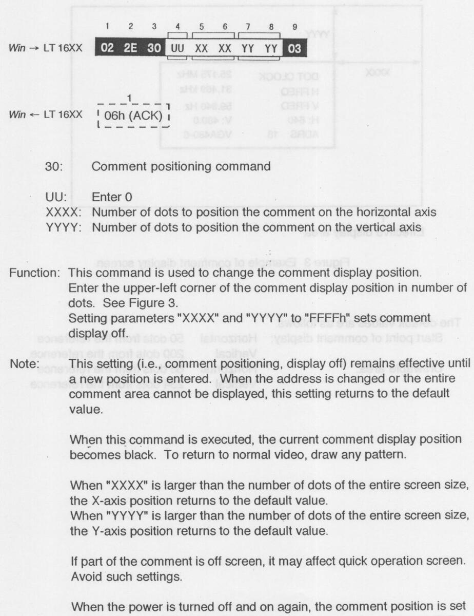
to default value (63, 234). The display depends on the setting of "DIP SW1-2" located in the user ROM compartment.
Refer to Section 5.3, "Setting the Panel DIP Switches" in the instruction manual supplied as a standard accessory.
7.8 Comment Character Change Command [ 02 2E 31 - - 03 ]
31: Comment character change command
UU: Enter 0
CC: Comment character
Function: This command is used to change comment character.
Note: Comment display mode should be set ON before executing this command.
The comment characters are effective until the comment or address is changed.
Up to eight characters can be used. When the comment is less than eight characters, enter 20h (space) in the remaining portion. Figure 4 shows an example.
| DOT CLOCK |
25.175 MHz
31.469 kHz |
|---|---|
| V FREQ | 59.940 Hz |
|
H: 640
ADRS 18 |
V: 480.0
VGA480-6 |
Figure 4 Comment display screen
The default values are as follows.
| Horizontal | 50 dots from the reference |
|---|---|
| Vertical | 200 dots from the reference |
| Horizontal | 63 dots from the reference |
| Vertical | 234 dots from the reference |
|
Horizontal
Vertical Horizontal Vertical |
7.10 Line Drawing Command [ 02 2E 61 - - 03 ]
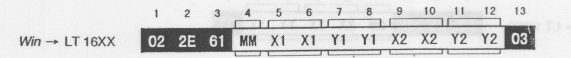
61: Line drawing command
MM: Drawing mode settings
00h: AND drawing in screen OFF mode
01h: OR drawing in screen OFF mode
80h: AND drawing in screen ON mode
81h: OR drawing in screen ON mode
Some drawing noises are displayed in ON mode.
AND: Black line
OR: White line
X1: Number of dots to set the line start position on the horizontal axis
Y1: Number of dots to set the line start position on the vertical axis
X2: Number of dots to set the line end position on the horizontal axis
Y2: Number of dots to set the line end position on the vertical axis
Function: This command is used to draw a line between the positions specified by the number of dots.
Vertical, horizontal, and slanted lines can be drawn.
The data input order is not specified.
Any data size for X1 and Y1, or X2 and Y2 in the effective screen area can be input.
Note: When part of data exceeds the screen size, the line is only drawn in the display area.
The upper-left corner of the screen (0, 0) is the reference for settings.
7.12 Fill-in of Circle Drawing Command [ 02 2E 63 - - 03 ]
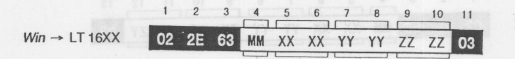
Win ← LT 16XX 106h (ACK)
63: Fill-in of circle drawing command
MM: Drawing mode settings
00h: AND drawing in screen OFF mode
01h: OR drawing in screen OFF mode
80h: AND drawing in screen ON mode
81h: OR drawing in screen ON mode
Some drawing noises are displayed in ON mode.
AND: Black circle
OR: White circle
XX: Number of dots to set the circle center position on the horizontal axis
YY: Number of dots to set the circle center position on the vertical axis
ZZ: Number of dots to set the radius
- Function: This command is used to draw a fill-in of circle specified by the number of dots.
- Note: When position data exceeds the screen size and the radius is within the screen size, the circle is only drawn in the display area. When radius exceeds the screen size, the circle is only drawn in the display area.
The upper-left corner of the screen (0, 0) is the reference for settings.
7.14 One Character Drawing Command [ 02 2E 65 - - 03 ]
65: One character drawing command
MM: Drawing mode settings
00h: AND drawing in screen OFF mode
01h: OR drawing in screen OFF mode
80h: AND drawing in screen ON mode
81h: OR drawing in screen ON mode
Some drawing noises are displayed in ON mode.
AND: Black character
OR: White character
CC: Character code (00 - FF)
FS: Font size
00h: 5 x 7 font
01h: 7 x 9 font
- CX: Character cell size (01 FF) on the horizontal axis
- CY: Character cell size (01 FF) on the vertical axis
- PX: Number of dots to set the character start position on the horizontal axis
- PY: Number of dots to set the character start position on the vertical axis
- Function: This command is used to draw one character with the desired font and cell size specified by the number of dots.
- Note: When data exceeds the screen size, the character is only drawn in the display area.
The upper-left corner of the screen (0, 0) is the reference for settings.
When either cell size (i.e., CX, CY) is 0, the character cannot be drawn.
7.15 All Character Drawing Command [ 02 2E 66 - - 03 ]
1 2 3 4 5 6 7 8 9 10 11 12 13 14 15 16 17 Win → LT 16XX 02 2E 66 MM CC FS CX CY BX BX BY BY EX EX EY EY 03
66: All character drawing command
MM: Drawing mode settings
00h: AND drawing in screen OFF mode
01h: OR drawing in screen OFF mode
80h: AND drawing in screen ON mode
81h: OR drawing in screen ON mode
Some drawing noises are displayed in ON mode.
AND: Black character
OR: White character
CC: Character code (00 - FF)
FS: Font size
00h: 5 x 7 font
01h: 7 x 9 font
CX: Character cell size (01 - FF) on the horizontal axis
CY: Character cell size (01 - FF) on the vertical axis
- BX: Number of dots to set the character start position on the horizontal axis
- BY: Number of dots to set the character start position on the vertical axis
- EX: Number of dots to set the character end position on the horizontal axis
EY: Number of dots to set the character end position on the vertical axis
- Function: This command is used to draw characters repeatedly with specified font and cell size at the position specified by the number of dots.
- Note: When data exceeds the screen size, the character is only drawn in the display area.
The upper-left corner of the screen (0, 0) is the reference for settings.
When either cell size (i.e., CX, CY) is 0, the character cannot be drawn.
7.17 Split Color-Gray Window Drawing Command [ 02 2E 80 - - 03 ]
| 1 | 2 | 3 | 4 | 5 | 6 | 7 | 8 | 9 | 10 | 11 | 12 | 13 | 14 | 15 | 16 | 17 | 18 | 19 | |
|---|---|---|---|---|---|---|---|---|---|---|---|---|---|---|---|---|---|---|---|
| Win → LT 16XX | 02 | 2E | 80 | MM | CC | DX | DY | ВΧ | ВХ | BY | BY | EX | EX | EY | EY | PS | PE | PP | 03 |
| 31 0 | 198 | it is t | 1000 | 10 | edin | UN | 100 | onv | - |
Win ← LT 16XX 106h (ACK)
80: Split color-gray window drawing command
MM: Drawing mode settings
00h: Drawing in screen OFF mode Graphic plane is cleared.
- 01h: Drawing in screen OFF mode Graphic plane is held.
- 80h: Drawing in screen ON mode Graphic plane is cleared.
- 81h: Drawing in screen ON mode Graphic plane is held.
Some drawing noises are displayed in ON mode.
- CC: Enter 1
- DX: Number of sections in X axis 1 - 16 (01h - 10h)
- DY: Number of sections in Y axis 1 - 16 (01h - 10h)
- BX: Window drawing start position on the horizontal axis (%)
- BY: Window drawing start position on the vertical axis (%)
- EX: Window drawing end position on the horizontal axis (%)
- EY: Window drawing end position on the vertical axis (%)
- PS: Pallet, "Start" (0 FFh)
- PE: Pallet, "End" (0 FFh)
- PP: Pallet, "Step" (0 FFh)
- Function: This command is used to draw a split color-gray window specified by the number of dots.
The window can be split up to 16 sections on the X and Y axes and colored respectively.
Refer to Section 7.19, "Color Pallet Setting Command [ 02 2E 88 - - 03 ]" for coloring.
Enter window size data on the horizontal and vertical axes in percentage (i.e., number of vertical or horizontal dots x 100).
7.18 Single-Color Color-Gray Window Drawing Command [ 02 2E 81 - - 03 ]
| 1 | 2 | 3 | 4 | 5 | 6 | 7 | 8 | 9 | 10 | 11 | 12 | 13 | 14 | 15 | 16 | 17 | |
|---|---|---|---|---|---|---|---|---|---|---|---|---|---|---|---|---|---|
| Win → LT 16XX | 02 | 2E | 81 | M1 | M2 | CC | WN | BX | ВХ | BY | BY | EX | EX | EY | EY | PS | 03 |
| 1-1-1-1 | L |
81: Single-color color-gray window drawing command
-
M1: Drawing mode settings
- 00h: Drawing in screen OFF mode Graphic plane is cleared.
- 01h: Drawing in screen OFF mode Graphic plane is held.
- 80h: Drawing in screen ON mode Graphic plane is cleared.
- 81h: Drawing in screen ON mode Graphic plane is held.
- Some drawing noises are displayed in ON mode.
-
M2: Color-gray window drawing mode settings
- 00h: Window is drawn after color-gray window data being set is cleared.
- 01h: Window is drawn by combining the color-gray window data being set.
- 02h: Setting is performed by combining the color-gray window data being set. No drawing is performed.
- CC: Enter 01
- WN: Color-gray window number Settable range: 0 - 7
- BX: Window drawing start position on the horizontal axis (%)
- BY: Window drawing start position on the vertical axis (%)
- EX: Window drawing end position on the horizontal axis (%)
- EY: Window drawing end position on the vertical axis (%)
- PS: Color pallet number (%)
Function: This command is used to draw a single-color color-gray window specified by the number of dots.
Up to eight windows (0 - 7) can be drawn.
Refer to Section 7.19, "Color Pallet Setting Command [ 02 2E 88 - - 03 ]" for coloring.
Enter window size in percentage (i.e., number of vertical or horizontal dots x 100).
7.19 Color Pallet Setting Command [ 02 2E 88 - - 03 ]
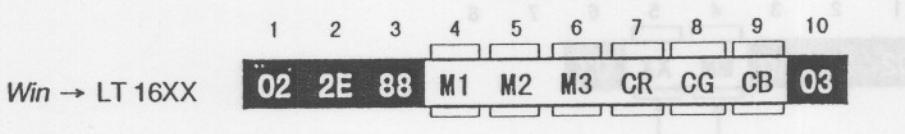
Win ← LT 16XX 1 06h (ACK)
- 88: Color pallet setting command
-
M1: Drawing mode settings
- 00h: Setting is only performed, no drawing.
- 01h: Setting and drawing are performed.
- M2: Analog/digital mode settings
00h: Both analog and digital
- 01h: Analog only
- 02h: Digital only
- M3: Pallet number to be set Settable range: 0 - FFh
- M3: Setting value for pallet R
- M3: Setting value for pallet G
- M3: Setting value for pallet B
-
Function: This command is used to set the color for the pallet RGB. Sections below should also be performed for this setting.
- 7.17, "Split Color-Gray Window Drawing Command [ 02 2E 80 - 03 ]" 7.18, "Single-Color Color-Gray Window Drawing Command [ 02 2E 81 - - 03 ]"
- Note: When setting multiple color pallets, execute this command repeatedly while changing the pallet number. Set drawing mode M1 to "00h" for faster operation because no drawing is performed during operation.
- Example: To draw multiple color pallets simultaneously, set M2 to 02h (except the last pallet), then set M2 to 00h or 01h for the last pallet. To draw four color pallets simultaneously, set M2 to 02h for pallets 1 through 3, then set M2 to 00h or 01h for pallet 4. Drawing four color pallets simultaneously
02, 2E, 88, 00, 00, 00, XX, 03, 02, 2E, 88, 00, 00, 01, XX, 03, 02, 2E, 88, 00, 00, 02, XX, 03, 02, 2E, 88, 01, 00, 03, XX, 03
Set M1 to 02h. Set M1 to 02h. Set M1 to 02h. Set M1 to 00h or 01h.
7.21 Flat Level Setting Command [ 02 2E A1 - - 03 ]
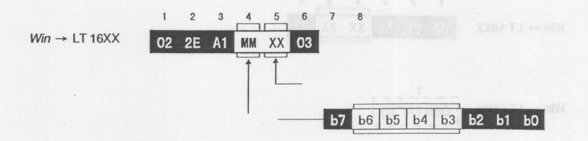
A1: Flat level setting command
XX: Flat level (00 - FFh, 256 steps)
| 01. | Enter | 0 | ||
|---|---|---|---|---|
| he | h2. | Entor | 0 |
| 00-00. | LINEIU | ||||
|---|---|---|---|---|---|
| b2: | Flat Level, R | 1: | ON | 0: | OFF |
| b1: | Flat Level, G | 1:1 | ON | 0: | OFF |
| b0: | Flat Level, B | 1: | ON | 0: | OFF |
* For b0 through b2, the level of the ON item depends on the XX value.
For b0 through b2, the level of the OFF item is held.
Function: This command is used to set a flat level (*) RGB. The level can be simultaneously or independently changed with the RGB ON flag. The settable range is 00h to FFh (255 in decimal number)
Note: Always set bit 7 of "MM" to 0.
(*) The flat level is the RGB level of flat field plane. The flat field plane is a plane that can be varied with the "FLAT Level" of the "Signal" tab in the "Timing set" program, and displayed in deepest of pattern numbers A0 (special pattern) and B1h (fill-in of circle pattern).
7.23 Add-Sync Setting Command [ 02 2E A3 - - 03 ]
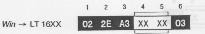
A3: Add-sync setting command
XXXX: Sync on/off 0000h: Sync off 0001h - FFFFh: Sync on
Function: This command is used to set the add-sync of analog G signal on/off.
Note: For the LT 1610A/1611/1612A, the add-sync can only be set on or off; the level cannot be set.
The sync level is automatically set according to the video level conforming to RS-343A standards. Refer to Section 7.3.1, "Setting the Analog Output" in the instruction manual supplied as a standard accessory.


 Loading...