


TV-FM SWEMAR GENERATOR
INSTRUCTION MANUAL
LEADER ELECTRONICS CORP.
LSW 251
TV-FM SWEMAR GENERATOR
TABLE OF CONTENTS
| 1. | INTRODUCTION | 1 |
|---|---|---|
| 2. | FEATURES | 1 |
| 3. | SPECIFICATIONS | 1 |
| 4. | BLOCK DIAGRAM | 2 |
| 5. | CONTROLS AND CONNECTORS | 3 |
| 6. | OPERATION INSTRUCTIONS | 6 |
| 6.1 Precautions | 6 | |
| 6.2 Preparation | . 6 | |
| 6.3 Operational Descriptions | 6 | |
| 6.4 Calibration of Marker Frequencies | 7 | |
| 6.5 Basic Connections and Accessory Circuits | 8 | |
| 7. | APPLICATIONS | 11 |
| 7.1 TV Tuner Checking | 11 | |
| 7.2 TV Intermediate-Frequency (IF) Amplifier Checking | 13 | |
| 7.3 Overall TV Response Checking | 13 | |
| 7.4 TV Sound Response Checking | 14 | |
| 7.5 IF Circuit Checking for FM Receivers | 15 | |
| 7.6 Tracking Checking for FM Receivers | 15 | |
| 7.7 Overall Response Checking for FM Receivers | 16 | |
| 7.8 Local Oscillator Checking | 16 | |
| 7.9 TV Color Bandpass Circuit Checking | 17 | |
| 7.9.1 First Bandpass Circuit Checking | 17 | |
| 7.9.2 Second Bandpass Ciruit Checking | 17 |
1. INTRODUCTION
The LSW 251 Swemar Generator is an integrated sweep and marker generator used for wide frequency band. An outstanding width of the generating frequency range provides the users with various applications, including tests and adjustments of TV receivers, FM tuners, CATV equipment, and tuning coils. The instrument is a requisite particularly for the after-sales service of TV receivers.
2. FEATURES
- (1) Sweep frequency is continuously variable in a range of 2 to 300MHz for a band.
- (2) Sweep generator's center frequency is electronically variable by using variable capacitance diode.
- (3) Maximum sweep width of 20MHz is suited for TV tuner checking.
- (4) Built-in circuit for automatic level control ensures constant output.
- (5) Variable attenuator is electronically controlled and continuously variable from 0 dB to -10 dB.
- (6) Markers are generated in a wide frequency range; on the needle, frequency bands are classified by color, and the scales have band indications for easy reading.
- (7) Marker adder circuit is incorporated.
- (8) Input terminal for external marker source is equipped.
- (9) Internal crystal-oscillator circuit requires no adjustment and its quartz crystal (FT-243) of 1 to 14MHz can be replaced.
- (10) Solid-state components allow less power consumption, compact size, and light weight.
3. SPECIFICATIONS
Sweep Generator
| Center Frequency: | 2 to 300MHz (1 band) |
|---|---|
| Sweep width: | Maximum 20MHz |
| Sweep method: | Variable capacitance diode |
| Sweep rate: | At 50/60Hz (Synchronous power frequency), triangular wave |
| Linearity: | Within 5% |
| Output voltage: | Approx. 100mVrms |
| Output impedance: | 75 ohms, unbalance |
| Attenuator: | Continuously varibale from 0dB to 10dB, by pushbuttons |
| (for 10dB, 20dB, and 20dB) | |
| Marker Generator | |
| Frequency range: | 2 to 250MHz (four bands) |
| Band A: 2 to 6.5MHz |
Band B: 6 to 18.5MHz
| Band C: 18 to 65MHz | |
|---|---|
| Band D: 60 to 250MHz (second harmonics) | |
| Frequency accuracy: | Within ±1% |
| Crystal oscillator: | 1 to 14MHz (quartz crystal replaceable) |
| Internal modulation: | Approx. 1kHz (amplitude modulation) |
| Accessory circuit: | Marker adder |
| Power supply: | AC100V 50/60Hz, approx. 12VA (120V, 240V) |
| Size and Weight: | 300(W) x 148(H) x 250(D) mm, approx, 4.8kg |
| Accessories: | BNC – BNC cable 2 |
| BNC – clip cable 2 | |
| Matching pad, 75 to 300 ohms (200 ohms) [LBN-07X] 1 | |
| Earphone 1 unit | |
| 4.5MHz or 5.5 MHz crystal (FT-243) 1 | |
| Spare Fuse 1 | |
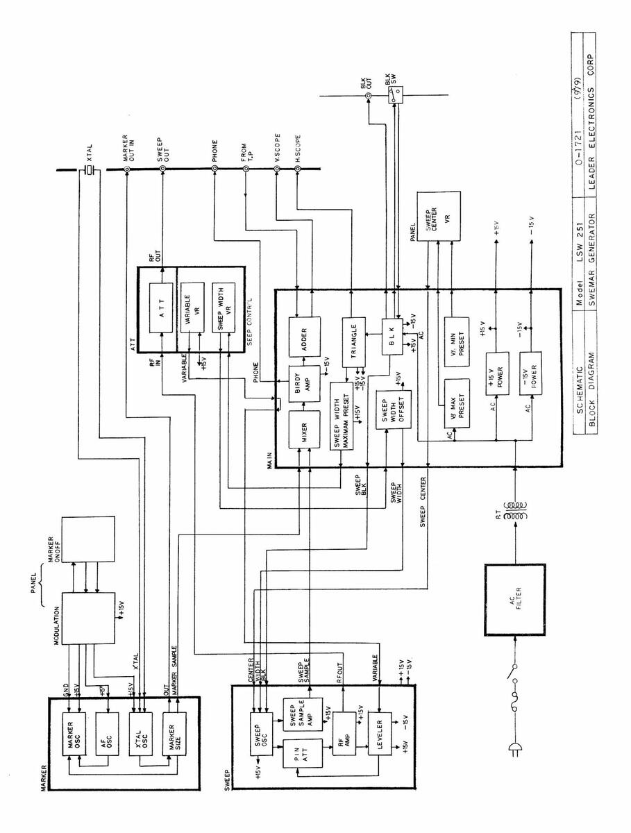
4. BLOCK DIAGRAM
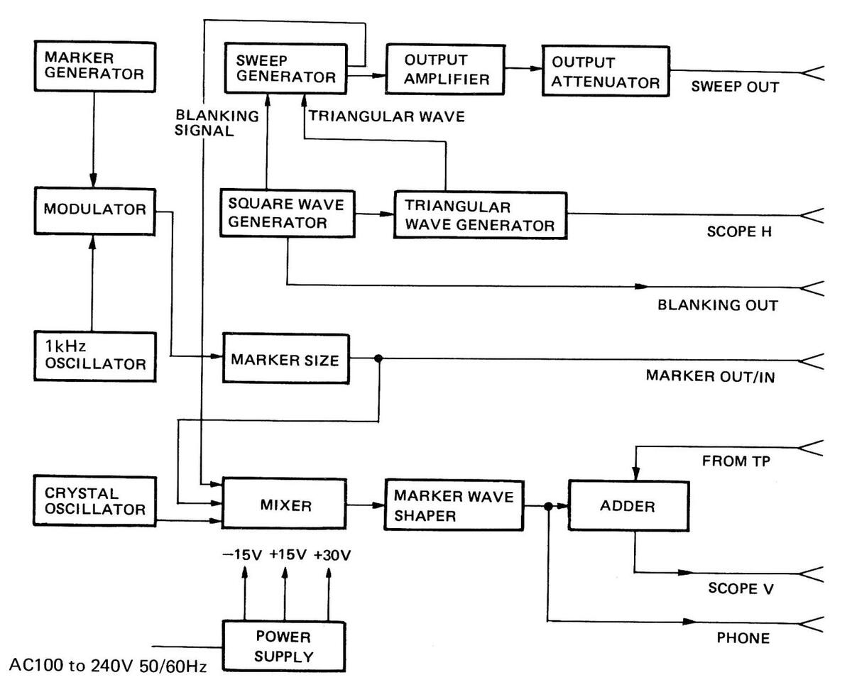
Figure 4-1
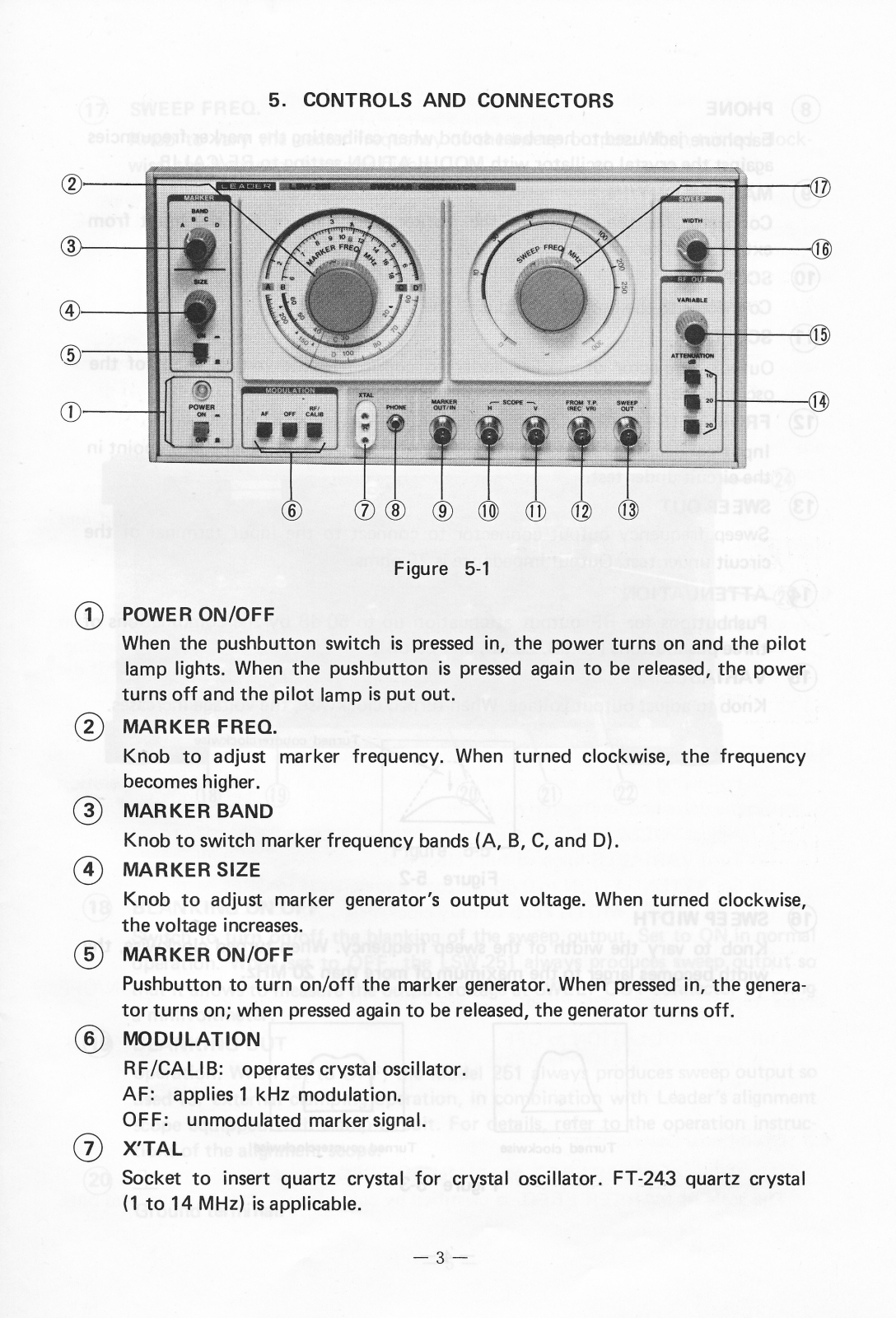
5. CONTROLS AND CONNECTORS
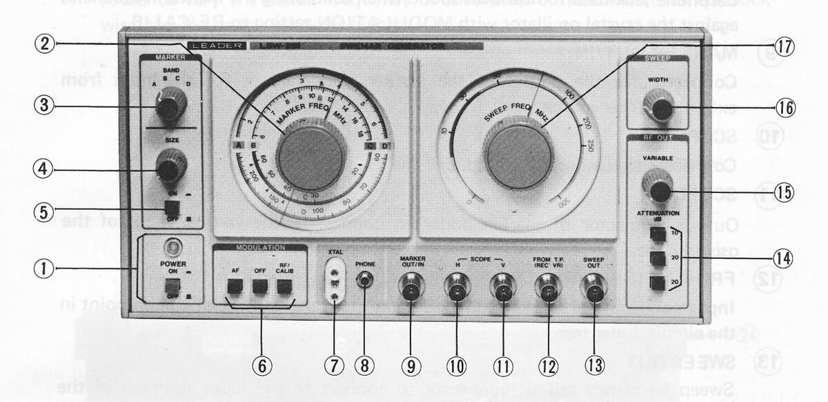

1) POWER ON/OFF
When the pushbutton switch is pressed in, the power turns on and the pilot lamp lights. When the pushbutton is pressed again to be released, the power turns off and the pilot lamp is put out.
(2) MARKER FREQ.
Knob to adjust marker frequency. When turned clockwise, the frequency becomes higher.
(3) MARKER BAND
Knob to switch marker frequency bands (A, B, C, and D).
(4) MARKER SIZE
Knob to adjust marker generator's output voltage. When turned clockwise, the voltage increases.
(5) MARKER ON/OFF
Pushbutton to turn on/off the marker generator. When pressed in, the generator turns on; when pressed again to be released, the generator turns off.
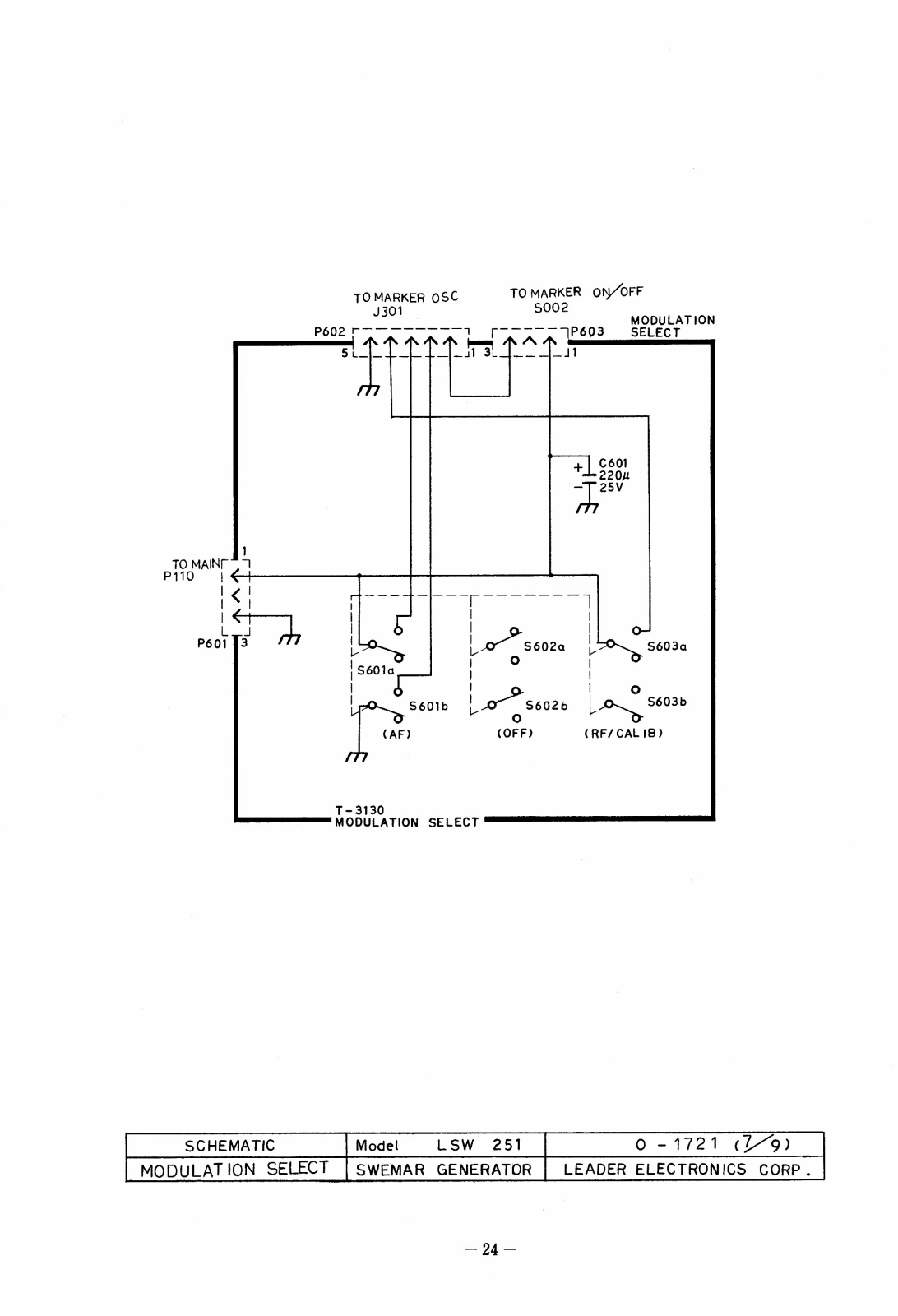
(6) MODULATION
RF/CALIB: operates crystal oscillator. AF: applies 1 kHz modulation. OFF: unmodulated marker signal.
(7) X'TAL
Socket to insert quartz crystal for crystal oscillator. FT-243 quartz crystal (1 to 14 MHz) is applicable.
(8) PHONE
Earphone jack used to hear beat sound when calibrating the marker frequencies against the crystal oscillator with MODULATION setting to RF/CALIB.
9 MARKER OUT/IN
Connector for the output of the marker frequency or for the input from external marker source.
(10) SCOPE H
Connector to the horizontal input of the oscilloscope.
(11) SCOPE V
Output connector of marker adder to connect to the vertical input of the oscilloscope.
(12) FROM TP (REC'VR)
Input connector of marker adder to connect to the test signal pickup point in the circuit under test.
(13) SWEEP OUT
Sweep frequency output connector to connect to the input terminal of the circuit under test. Output impedance is 75 ohms.
(14) ATTENUATION
Pushbuttons for RF output attenuation up to 50 dB by the combinations of three pushbuttons (10 dB, 20 dB, and 20 dB).
(15) VARIABLE
Knob to adjust output voltage. When turned clockwise, the voltage increases.
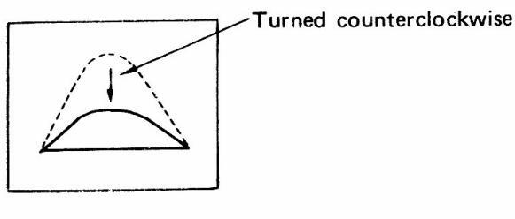
Figure 5-2
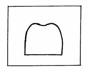
16) SWEEP WIDTH
Knob to vary the width of the sweep frequency. When turned clockwise, the width becomes larger to the maximum of more than 20 MHz.
Turned clockwise
Turned counterclockwise
Figure 5-3
(17) SWEEP FREQ.
Knob to vary the center frequency of the sweep output. When turned clockwise, the frequency becomes higher.
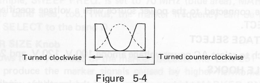
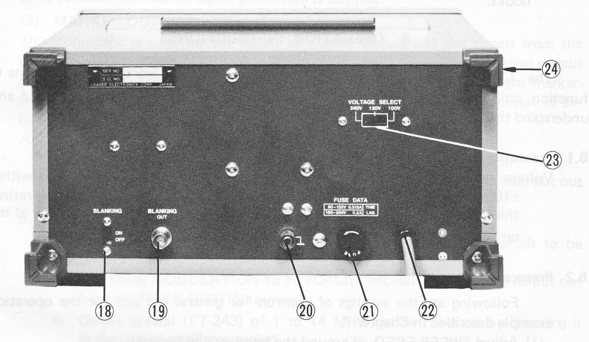
Figure 5-5
(18) BLANKING ON OFF
Switch to turn on/off the blanking of the sweep output. Set to ON in normal operation. When set to OFF, the LSW 251 always produces sweep output so that it allows to measure the output voltage at SWEEP OUT connector by using a millivoltmeter.
(19) BLANKING OUT
operation. When set to OFF, the Model 251 always produces sweep output so used for external clamping operation, in combination with Leader's alignment scope equipped with clamp circuit. For details, refer to the operation instructions of the alignment scope.
20
٦
Ground terminal.
(21) FUSE
Fuse holder. Turn counterclockwise to unfasten it. Fuse rating: Refer to FUSE DATA on the rear panel.
(22) POWER CABLE
To be connected to the power source with a voltage specified by VOLTAGE SELECT.
23 VOLTAGE SELECT
Switch to select AC power voltage among 100 V, 120 V, and 240 V.
(24) CABLE HOOKS
When the power cable is too long, adjust the length by winding it around the hooks.
6. OPERATION INSTRUCTIONS
The LSW 251 with various functions and features requires correct operations to function properly without causing troubles. Therefore, users must carefully read and understand the following operation instructions before starting the operation.
6.1 Precautions
Voltage rating: Care must be taken to ensure that the power voltage is within ±10 % of the rated voltage. If the voltage is less than -10 % of the rating, the LSW 251 may not operate properly. If the voltage exceeds +10% of the rating, burning may possibly occur.
6.2 Preparation
Following are the settings of controls for general use and for the operation example described in Chapter 7.
- (1) Adjust SWEEP FREQ. at around the frequency to be used.
- (2) Turn VARIABLE knob to fully clockwise.
- (3) Set ATTENUATION to 0 dB (all the three switches to OFF).
- (4) Turn SWEEP WIDTH knob to fully clockwise.
- (5) Adjust MARKER FREQ. at the frequency to be used.
- (6) Set MARKER BAND to the proper frequency band.
- (7) Adjust MARKER SIZE at the middle position, and push in MARKER ON/OFF switch.
- (8) Set MODULATION to OFF.
- (9) Insert quartz crystal (FT-243) to the crystal-oscillator socket.
- (10) Push in POWER ON/OFF switch, and be sure the pilot lamp lights.
6.3 Operational Descriptions
(1) Colors of SWEEP FREQ. and MARKER FREQ. Scales
The scale of MARKER FREQ. is classified by color, in red, yellow, green, and blue,
according to the frequency bands. SWEEP FREQ. scale also has a rough color classification similar to the MARKER FREQ. scale. The colors will help a quick, accurate setting of the frequency to be used. In addition, frequency-band names are written at the side of the dial needles to simplify MARKER frequency reading. When, for example, SWEEP FREQ. is set to 70 MHz (blue area), MARKER FREQ. will be in blue band area, too. Thus, the marker frequency can be generated by setting BAND SELECT to the band D.
(2) MARKER SIZE Knob
This knob allows to vary the size of the marker. Because the LSW 251 is wide-band type, it may produce the marker signals caused by higher harmonics. Therefore, make sure the size of the marker is proper. By pressing MARKER ON/OFF switch to be released, the marker-signal generation is stopped.
(3) MARKER OUT/IN Connector
This connector is used for the ouput of marker signals and the signals from the crystal oscillator. When MARKER SIZE knob is turned clockwise, the signal output goes high. When MARKER ON/OFF switch is pressed to be released, the marker-signal generation is stopped. The same connector can be used for the input of external signal source.
-
A. As a marker generator:
- a. Marker signals can be put out from MARKER OUT/IN connector.
- b. By setting MODULATION to AF, AM wave of about 1 kHz can be put out from the connector.
-
B. As a crystal oscillator:
- a. Marker generation stops by pressing MARKER ON/OFF switch to be released.
- b. By setting MODULATION to RF/CALIB, oscillated signals can be put out from MARKER OUT/IN terminal.
- c. Quartz crystal (FT-243) of 1 to 14 MHz can be replaced by inserting it in the crystal-oscillator socket.
6.4 Calibration of Marker Frequencies
-
(1) Using Crystal Oscillator:
- a. Insert quartz crystal into the oscillator socket, and set MODULATION to RF/CALIB.
- b. Connect the earphone to PHONE jack firmly, and listen to the beat sound by the earphone.
- c. Frequencies to be checked by this method are listed in Table 6-1.
|
Quartz crystal
Band |
4.5 N | ЛНz | 5.5 MHz | |||||
|---|---|---|---|---|---|---|---|---|
| А | BAND | 4.5 | 5.5 | |||||
| В | BAND | 9.0 | 9.0 13.5 18.0 | .0 1 | 6.5 | |||
| 18.0 | 22.5 | 27.0 | 22.0 | 27.5 | 33.0 | |||
| BAND | 31.5 | 36.0 | 40.5 | 38.5 | 44.0 | 49.5 | ||
| С | 45.0 | 49.5 | 54.0 | 55.0 | 60.5 | |||
| 58.5 | 63.0 | |||||||
| 63.0 | 67.5 | 72.0 | 60.5 | 66.0 | 71.5 | |||
| 76.5 | 81.0 | 85.5 | 77.0 | 82.5 | 88.0 | |||
| D | BAND | 90.0 | 94.5 | 99.0 | 93.5 | 99.0 | 104.5 | |
| 103.5 | 108.0 | 112.5 | 110.0 | 115.5 | 121.0 | |||
| 117.0 | 121.5 | 126.5 | ||||||
Table 6-1
(2) Using External Marker Source:
- a. Make connections as shown in Figure 6-1.
- b. Adjust SWEEP FREQ. at the frequency to be calibrated.
- c. As shown in Figure 6-2, markers of the LSW 251 and external marker source appear on the oscilloscope.
- d. Adjust MARKER FREQ. so that the LSW 251's marker aligns with the marker of external source.
- e. Beat sound can be heard by means of the earphone.
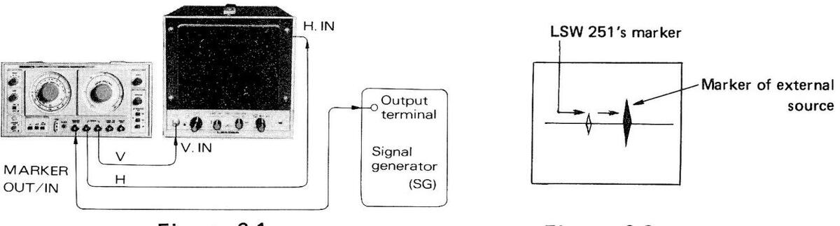

Figure 6-2
(3) Using a Frequency Counter:
- a. Connect a counter to MARKER OUT/IN connector.
- b. Perform the calibration by reading the frequencies on the counter.
6.5 Basic Connections and Accessory Circuits
An oscilloscope used with the LSW 251 is recommended to be highly sensitive. Its frequency response may be at 10 kHz.
(1) Basic Connections and Marker Adder Circuit
Figure 6-3 shows the basic connections of the LSW-251 with other instruments.
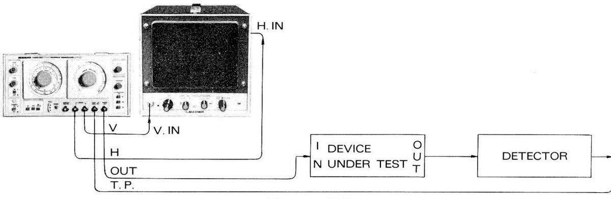
Figure 6-3
Following is an explanation of the marker adder circuit, a special feature of the LSW 251. The basic connections of Figure 6-3 can be shown in block diagram below (Figure 6-4).
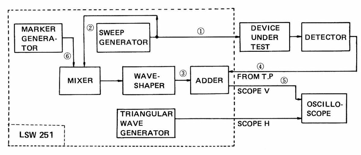
Figure 6-4
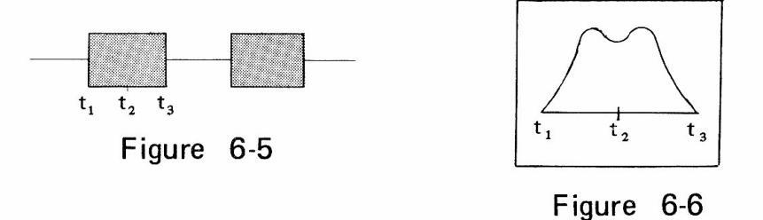
Signal (1) in Figure 6-4 is as shown in Figure 6-5 (when BLANKING set to ON). The signal (1) forms response curve of the device under test: for example, when TV tuner is tested, waveform as shown in Figure 6-6 appears in the output signal (4).
Signal (2) is same as the signal (1), but used to produce marker signal (6) and the beat ("birdy" marker).
The signals (2) and (6) are mixed in MIXER to be as shown in Figure 6-7; the "birdy" marker shows the position (frequency).
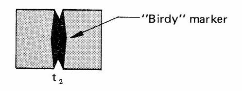
Figure 6-7
The "birdy" marker, black part in Figure 6-7, appears in signal ③. Its width depends on the frequency response of MARKER WAVESHAPER. The singals ③ and ④ are combined in the adder circuit, and oscilloscope displays the waveform as shown in Figure 6-8.
The MIXER, MARKER WAVESHAPER, and ADDER in Figure 6-4 are called marker adder circuit, which allows to retain response curve of the device under test for the checking. However, there is a little loss of the response caused by the ADDER.
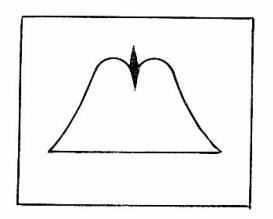
Figure 6-8
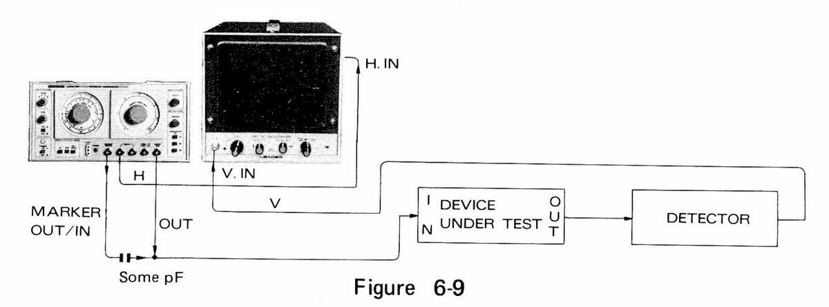
If an oscilloscope with low sensitivity is used, or if the output of the device under test is low, the instruments and the circuits must be connected as shown in Fig. 6-9. In this case, note that a capacitor of some pF must be used between sweep output and marker output.
(2) Detector
A sweep generator generally displays waveform detected from the device under test on an oscilloscope. Therefore, if the device under test does not have detection function, a detector must be connected to the output of the circuit. Figure 6-10 shows the connection example.
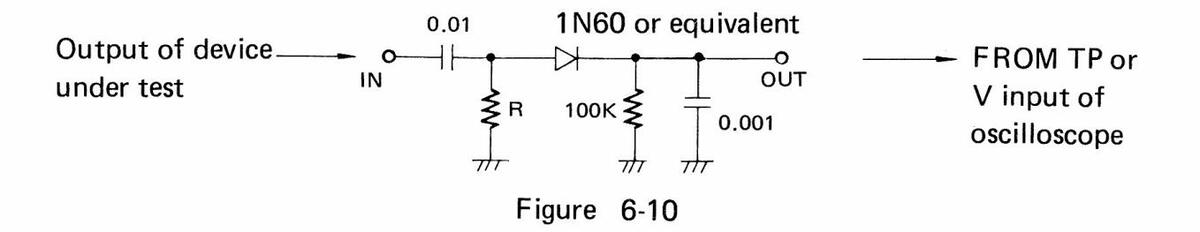
Note that the input resistance R of the detector must match with the output impedance of the device under test.
(3) BLANKING ON/OFF Switch and BLANKING OUT Terminal
The BLANKING ON/OFF switch located on the rear panel of the LSW 251 is set to ON in normal operation. In this setting, when the sweep is done from left to right on the scope, the output is provided from SWEEP OUT, but when the sweep is done from right to left on the scope, the output is not provided.
By setting BLANKING ON/OFF switch to OFF, the output is always provided; thus, the setting is useful for measuring output level.
BLANKING OUT connector makes the signal output in the timing as shown in Figure 6-11. The output connector is used for clamp operation of an alignment oscilloscope with clamp.
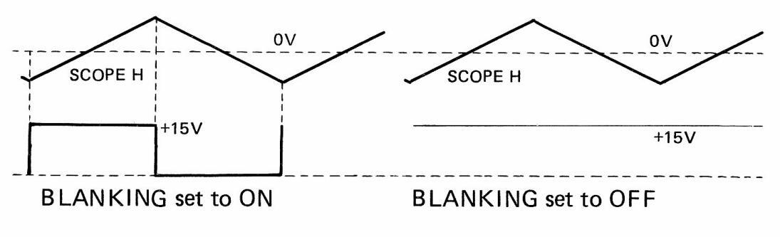
Figure 6-11
7. APPLICATIONS
7.1 TV Tuner Checking
- (1) Make the connections as shown in Fig. 7-1.
- (2) Adjust SWEEP FREQ. at around a specified frequency (see Table 7-1): for example, at around 57 MHz for channel 2.
- (3) Adjust MARKER FREQ. at the video carrier frequency: for example, at 55.25 MHz for channel 2.
- (4) Insert 4.5 MHz quartz crystal (FT-243).
- (5) Set MODULATION to RF/CALIB.
- (6) Figure 7-2 shows the output waveform in this setting.
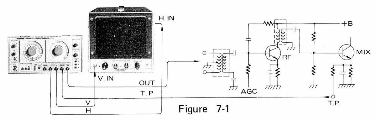
Notes: For a TV tuner with antenna input impedance of 300 ohms, use Matching Pad supplied as accessories. Markers marked by * in Figure 7-2 are the side markers generated by
4.5 MHz quartz crystal, and the marker 4.5 MHz higher than the videocarrier-frequency marker shows sound carrier frequency.
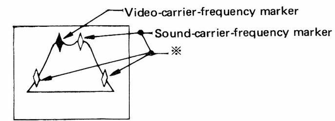
Figure 7-2
| Table 7-1 Television channel fro | equency chart |
|---|
|
VHF
(USA) |
CHAN
No. |
Video
Carrier |
Sound
Carrier |
Band |
|---|---|---|---|---|
| MHz | MHz | MHz | ||
| 2 | 55.25 | 59.75 | 54 — 60 | |
| 3 | 61.25 | 65.75 | 60 — 66 | |
| 4 | 67.25 | 71.75 | 66 — 72 | |
| 5 | 77.25 | 81.75 | 76 — 82 | |
| 6 | 83.25 | 87.75 | 82 — 88 | |
| 7 | 175.25 | 179.75 | 174 — 180 | |
| 8 | 181.25 | 185.75 | 180 — 186 | |
| 9 | 187.25 | 191.75 | 186 — 192 | |
| 10 | 193.25 | 197.75 | 192 — 198 | |
| 11 | 199.25 | 203.75 | 198 — 204 | |
| 12 | 205.25 | 209.75 | 204 — 210 | |
| 13 | 211.25 | 215.75 | 210 — 216 | |
| , |
Intermediate Frequencies:
Video IF Carrier Sound IF Carrier Color Sub-carrier
45.75MHz 41.25MHz 42.17MHz
(Nominal)
7.2 TV Intermediate-Frequency (IF) Amplifier Checking
- (1) Make connections as shown in Figure 7-3.
- (2) Adjust SWEEP FREQ. at around 45.75 MHz.
- (3) Adjust SWEEP WIDTH at an appropriate value.
- (4) Adjust MARKER FREQ. at 45.75 MHz.
- (5) Set MODULATION to RF/CALIB, and generate a 4.5 MHz side marker.
- (6) Figure 7-4 shows the waveform on oscilloscope.
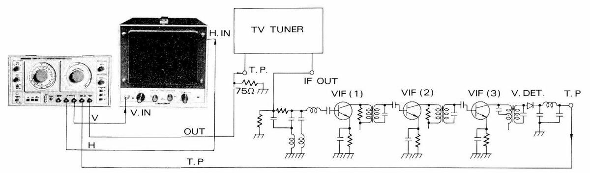

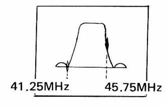
Figure 7-4
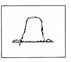
Figure 7-5
* The response curve may possibly be not clear (as shown in Figure 7-5), influenced by the horizontal signal of the TV. It is recommended to disable the horizontal circuit and to set the tuner to an unused channel.
7.3 Overall TV Response Checking
- (1) Make connections as shown in Figure 7-6.
- (2) Adjust SWEEP FREQ. at the channel frequency under test.
- (3) Set ATTENUATION to more than 30 dB.
- (4) Adjust SWEEP WIDTH at an appropriate value.
- (5) Adjust MARKER FREQ. at the video carrier wave frequency under test.
- (6) Set MODULATION to RF/CALIB, and generate a 4.5 MHz side marker.
- (7) Figure 7-7 shows the waveform on oscilloscope.
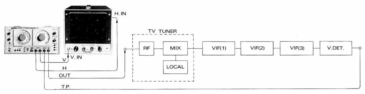
Figure 7-6
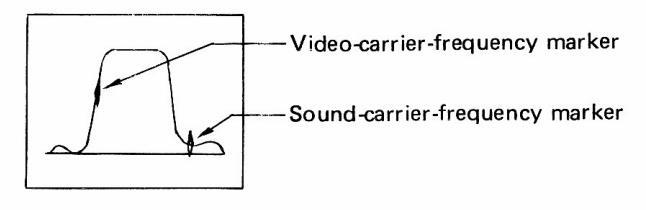
Figure 7-7
7.4 TV Sound Response Checking
- (1) Make connections as shown in Figure 7-8.
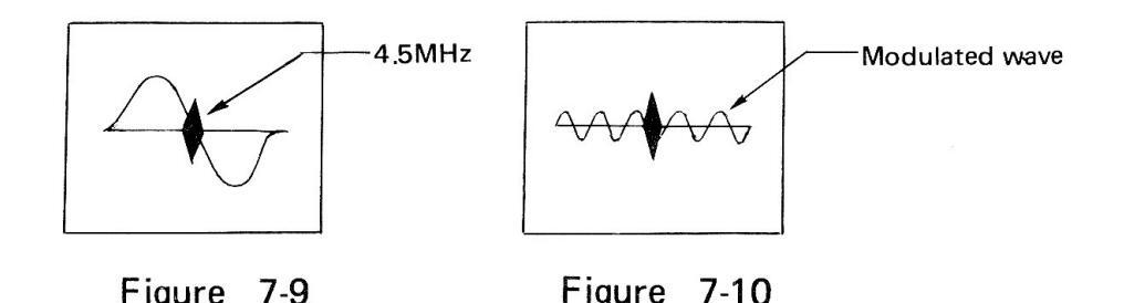
- (2) Adjust SWEEP FREQ. at around 4.5 MHz.
- (3) Adjust SWEEP WIDTH at an appropriate value.
- (4) Adjust MARKER FREQ. at 4.5 MHz.
- (5) Adjust the 4.5 MHz marker at the base line intersection as shown in Figure 4-9.
- (6) If the marker is not clear for the procedure (5), the output cable connected to the SWEEP OUT terminal may be disconnected and newly connected to the MARKER OUT/IN connector (the connection indicated by a dot line in Figure 7-8).
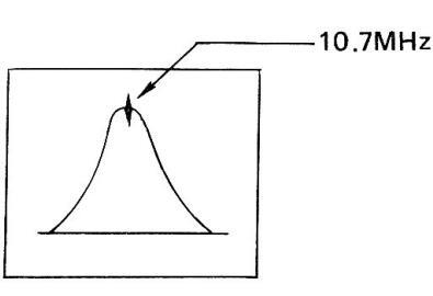
- (7) Set MODULATION to AF.
- (8) Adjust the modulated wave (as shown in Figure 7-10) to become minimum.
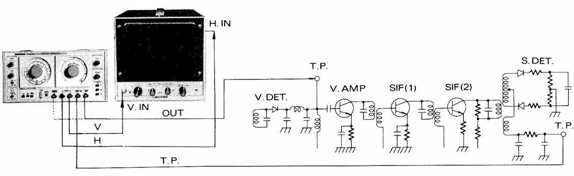
Figure 7-8
* When checking TV receivers, study carefully the manuals or operation instructions provided by manufacturers. Moreover, refer to the magazines and books explaining high-frequency amplifiers and intermediate-frequency amplifiers in details.
7.5 IF Circuit Checking for FM Receivers
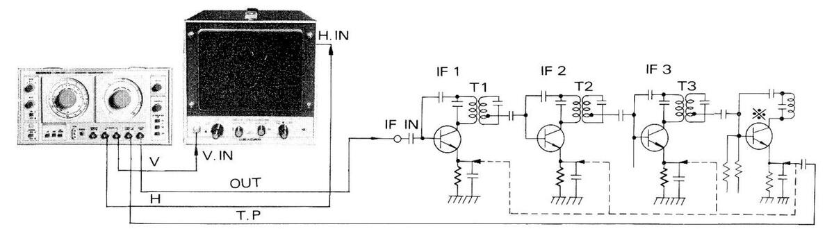
- (1) Make connections as shown in Figure 7-11.
- (2) Adjust SWEEP FREQ. at around 10.7 MHz.
- (3) Adjust SWEEP WIDTH at an appropriate value.
- (4) Adjust MARKER FREQ. at 10.7 MHz.
- (5) Figure 7-12 shows the waveform on oscilloscope.

7.6 Tracking Checking for FM Receivers
Figure 7-11
- (1) Make connections as shown in Figure 7-13.
- (2) Adjust SWEEP FREQ. at the middle of the FM BAND.
- (3) Turn SWEEP WIDTH knob to fully clockwise.
- (4) Figure 7-14 shows the waveform on oscilloscope.
- (5) By turning the receiver's tuning knob, check tracking frequencies with various MARKER FREQ. settings.
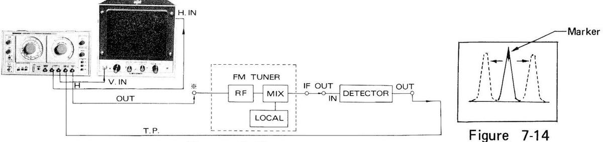
Figure 7-13
* The sweep output impedance must match with the impedance of the receiver's antenna input.
7.7 Overall Response Checking for FM Receivers
- (1) Make connections as shown in Figure 7-15.
- (2) Adjust SWEEP FREQ. at the checking in the FM Band.
- (3) Adjust SWEEP WIDTH at an appropriate value.
- (4) Adjust MARKER FREQ. at the tracking frequency under test.
- (5) Figure 7-16 shows the waveform on oscilloscope.
- (6) Provide a modulated wave in the same procedures described in 7.4 TV Sound Response Checking.
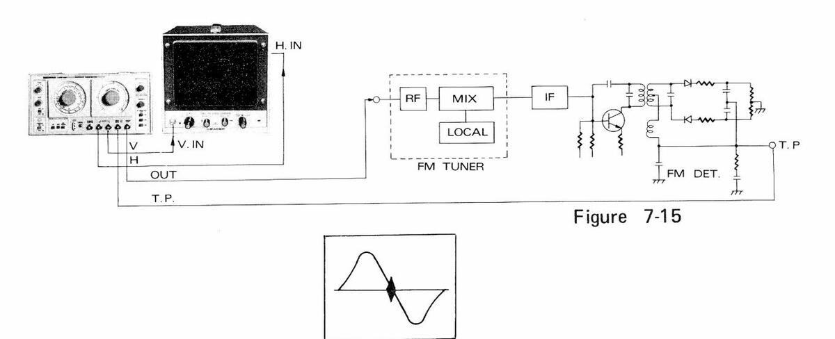
Figure 7-16
7.8 Local Oscillator Checking
The local oscillators in the receivers can be checked in the same procedures described in 6.4.2 Calibration of MARKER Frequencies, Using External Marker Source. The local oscillator in TV tuner, for example, is checked as follows:
- (1) Make connections as shown in Figure 7-17.
- (2) Adjust SWEEP FREQ. at around 45.75 MHz plus video carrier frequency.
- (3) Adjust MARKER FREQ. at 45.75 MHz + video carrier frequency.
- (4) Connect MARKER OUT/IN connector and the point to be checked (or the point leaking oscillation) of the circuit under test.
- (5) Align the local oscillation with the LSW 251's marker, as shown in Figure 7-18.
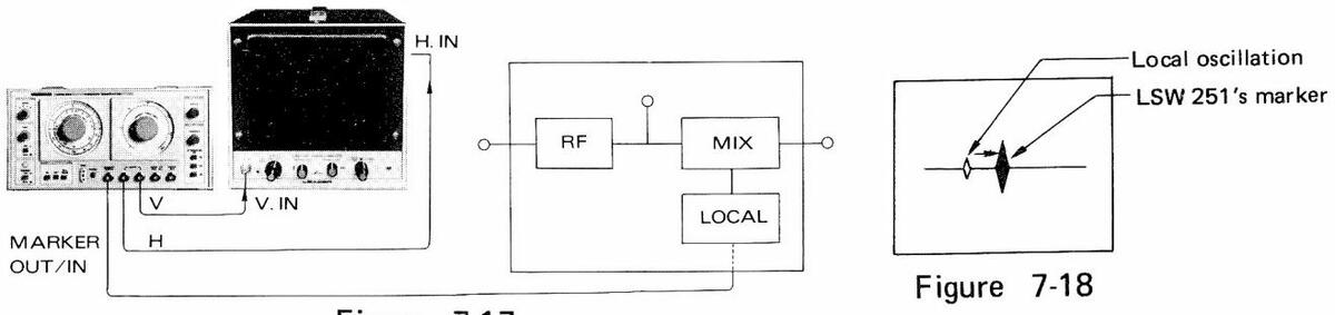
Figure 7-17
7.9 TV Color Bandpass Circuit Checking
7.9.1 First bandpass circuit
- (1) Make connections as shown in Figure 7-19.
- (2) Adjust SWEEP FREQ. at around 3.58 MHz.
- (3) Adjust SWEEP WIDTH at an appropriate value: e.g., 3 MHz.
- (4) Adjust MARKER FREQ. at 3.58 MHz.
- (5) Set MODULATION to RF/CALIB, and generate a 4.5 MHz marker.
- (6) Figure 7-20 shows the waveform on socilloscope.
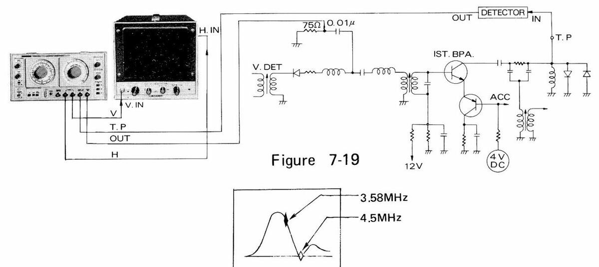
Figure 7-20
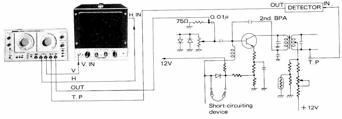
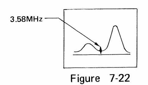
7.9.2 Second bandpass circuit
- (1) Make connections as shown in Figure 7-21.
- (2) Adjust SWEEP FREQ. at around 3.58 MHz.
- (3) Adjust SWEEP WIDTH at an appropriate value.
- (4) Adjust MARKER FREQ. at 3.58 MHz.
- (5) Figure 7-22 shows the waveform on oscilloscope.

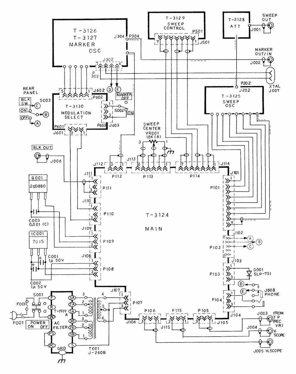
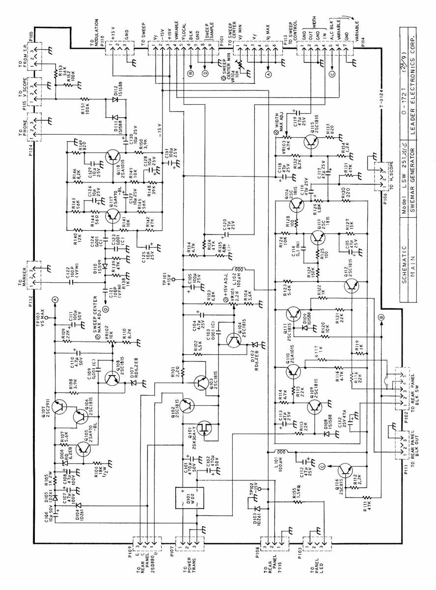
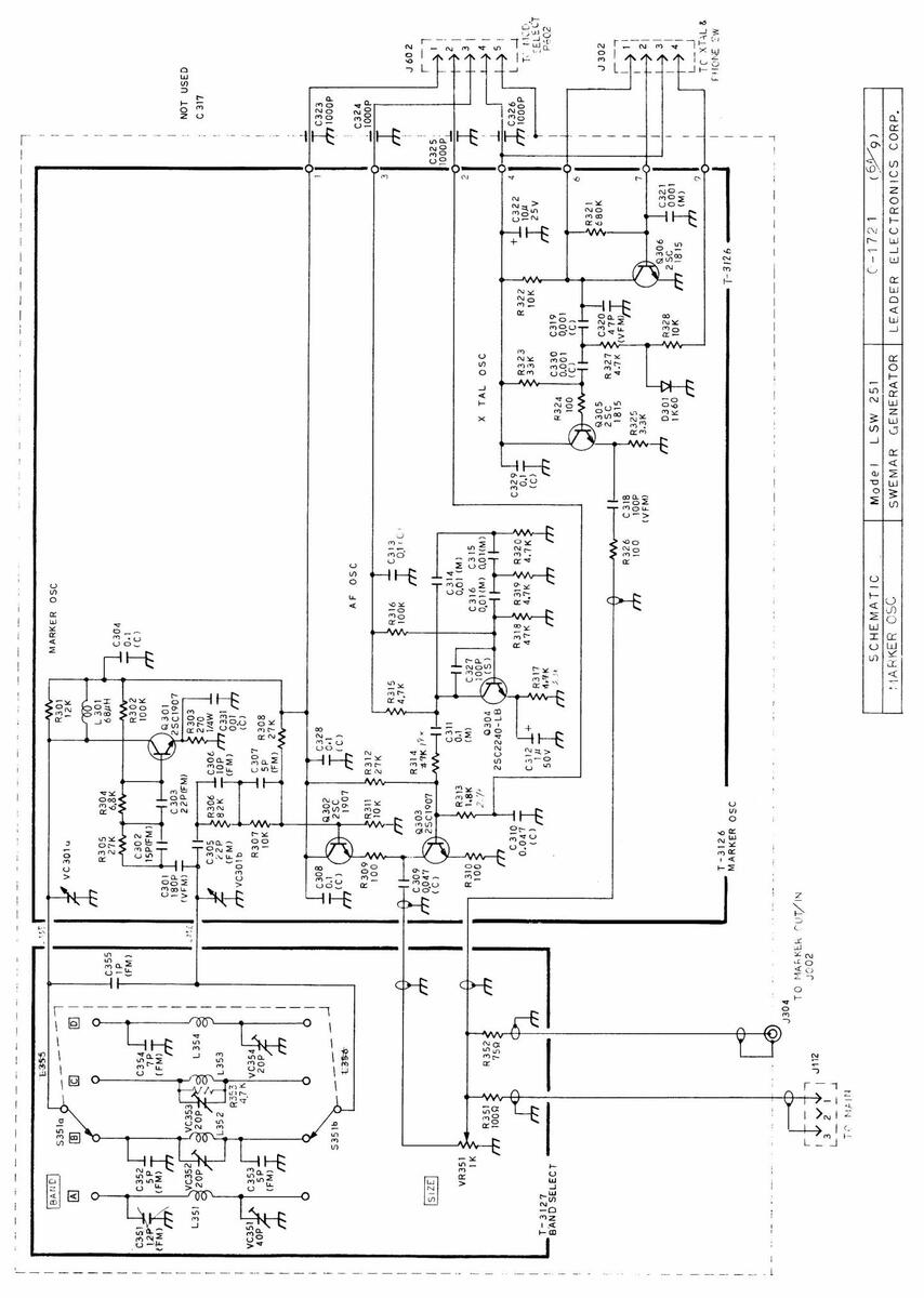
| SCHEMATIC | Model LSW 251 | 0-1721 (149) |
|---|---|---|
| WIRING DIAGRAM | SWEMAR GENERATOR | LEADER ELECTRONICS CORP. |
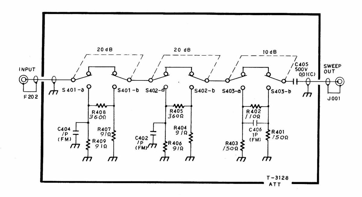
| SCHEMATIC | Model | LSW | 2 5 1,251-5 | 0 - 1 | 721 | (44 9) | |
|---|---|---|---|---|---|---|---|
| ATTENUATOR | SWEMAR | GENE | RATOR | LEADER | ELECI | RONICS | CORP. |
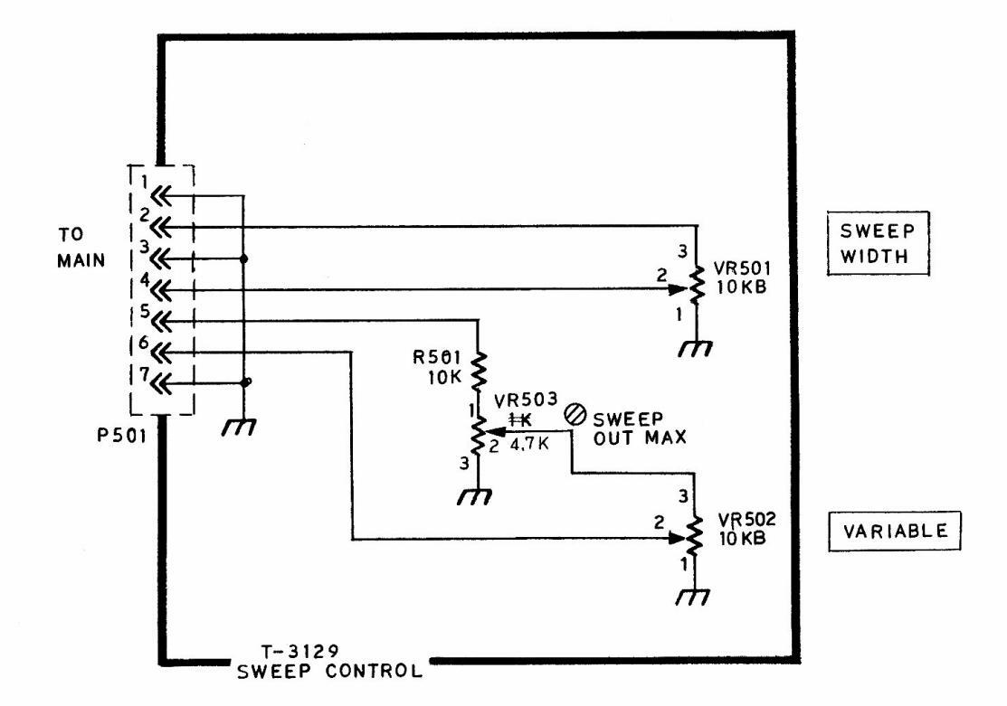
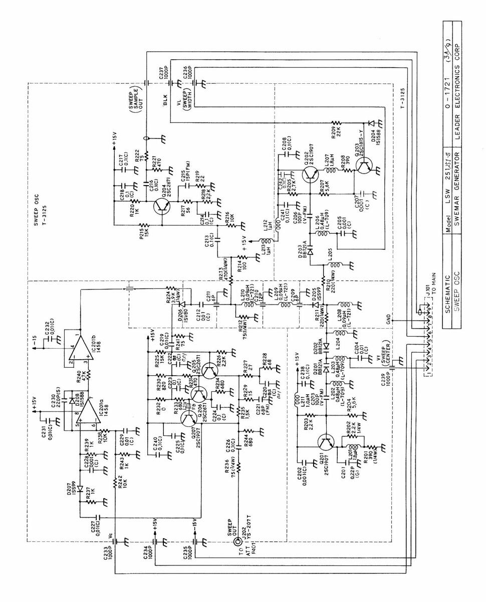
| SCHEMATIC | Model LSW 251,251;$ | 0 1721 (54 9) |
|---|---|---|
| SWEEP CONTROL | SWEMAR GENERATOR | LEADER ELECTRONICS CORP. |
— 23 —
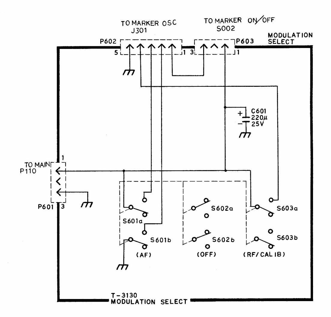
| SCHEMATIC | Model | LSW 251 | 0 - 1721 (7/9) |
|---|---|---|---|
| MODULATION SELECT | SWEMAR | GENERATOR | LEADER ELECTRONICS CORP. |

1 : 100 V 2: 120 V 3: 240 V
| SCHEMATIC | Model | LSW | 251 | 0 | 1721 | (84 | 9) | |
|---|---|---|---|---|---|---|---|---|
| AC FILTER | SWEMAR | GENER | ATOR | LEADER | EL | ECTRO | NICS | CORP. |
- 26 -

LEADER ELECTRONICS CORP. 2-6-33 TSUNASHIMA-HIGASHI, KOHOKU-KU, YOKOHAMA, JAPAN.
PHONE:(045)541-2123 FAX:(045)544-1280 TELEX:J47780 JPLEADER
LEADER INSTRUMENTS CORP. 380 OSER AVENUE, HAUPPAUGE, N. Y. 11788 U.S. A.
PHONE: (516) 231-6900 TELEX:510-227-9669 LEADER HAUP FAX:516-231-5295


 Loading...