

LEAD dynamic PDW Series, PDC Series, PDW30, PDW62, PDW120 Operating Manual
...
VERSION 2.1 10/15
BEDIENUNGSANLEITUNG
OPERATING MANUAL
MANUEL D’UTILISATION
HANDLEIDING
BRUKSANVISNING
NÁVOD KOBSLUZE
NÁVOD NA POUŽITIE
INSTRUCŢIUNI DE UTILIZARE
LED PANEL DYNAMIC
PDW/PDC
PDW30 Art. Nr. 70200027
PDW60 Art. Nr. 70200025
PDW62 Art. Nr. 70200023
PDW120 Art. Nr. 70200024
PDW120 SLIM Art. Nr. 70200026
PDC30 Art. Nr. 70200027
PDC62 Art. Nr. 70200028
DEUTSCH
Vielen Dank, dass Du Dich für ein Produkt der LEAD
energy AG entschieden hast. Falls Du unseren
Service erreichen möchtest, sind wir für Dich auf
unserer Homepage und per E-Mail erreichbar.
Bestimmungsgemäße Verwendung Hinweis
Du kannst die Panel PDW und PDC in Rasterdecken
einbauen oder sie mit optional erhältlichem Zubehör
als Deckenaufbauleuchte oder abgehängte Leuchte
montieren.
1
Montage
Beachte, dass der WLAN-Controller Deiner Leuchte
zur Konfiguration des Produkts zugänglich sein
muss. Du kannst Deine Leuchte auch vor der Montage konfigurieren. Die Einstellungen bleiben auch
nach dann erhalten, wenn Du die Stromversorgung
trennst. Notiere Dir die SSID und das Passwort des
WLAN-Controllers.
Beachte vor der Installation zwingend die bei-
liegenden Warnhinweise!
1.1
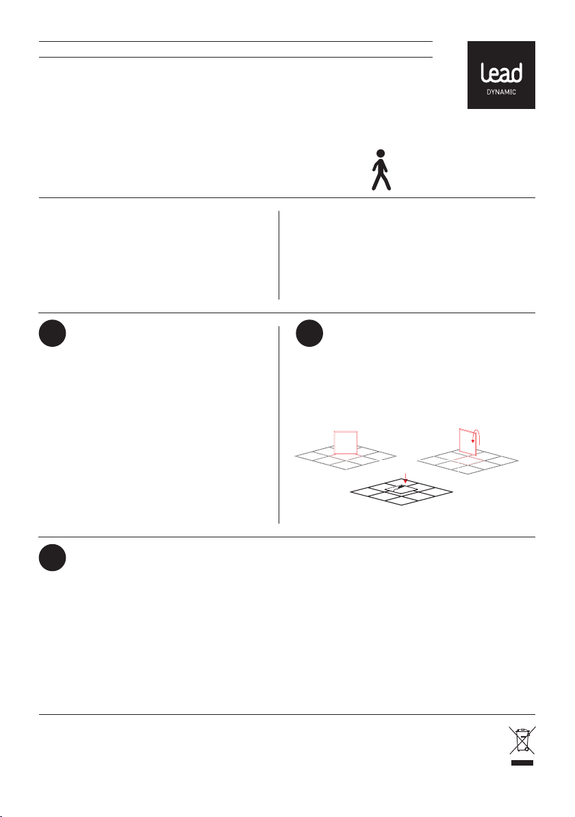
Du kannst Dein PDC oder PDW in Rasterdecken einbauen, indem Du eine Deckenplatte durch das Panel
ersetzt. Die Größe der Deckenplatte muss dabei
?
service@lead-energy.com
www.lead-energy.com
Montage in Rasterdecken
1.2
Montage in abgehängte Decken (diese Montageart ist nur bei den PDW-Panels möglich)
Befestige die beiliegenden Federhalter mit den Schrauben an Deinem Panel. Stelle einen Deckenausschnitt her;
die Größe des Ausschnitts kannst Du der folgenden Auflistung entnehmen: PDW 30: 289 x 289 mm, PDW 62: 609 x
609 mm, PDW 60: 589 x 289 mm, PDW 120 SLIM: 1189 x 139 mm und PDW 120: 1189 x 289 mm
Den Ausschnitt musst Du sehr präzise ausführen. Die Ränder des Ausschnitts müssen das Gewicht der Leuchte
tragen können.
Stelle in der Decke den elektrischen Anschluss des Netzkabels her. Setze das Panel in den Deckeneinschnitt ein,
indem Du die Federhalter zurück drückst. Gehe sicher, dass das Panel vollständig eingerastet ist.
LEAD ENERGY AG Am Stadtbad 37 45219 Essen-Kettwig Irrtümer und Änderungen vorbehalten Informationen / technischer Support: www.lead-energy.com
DEUTSCH
1.3
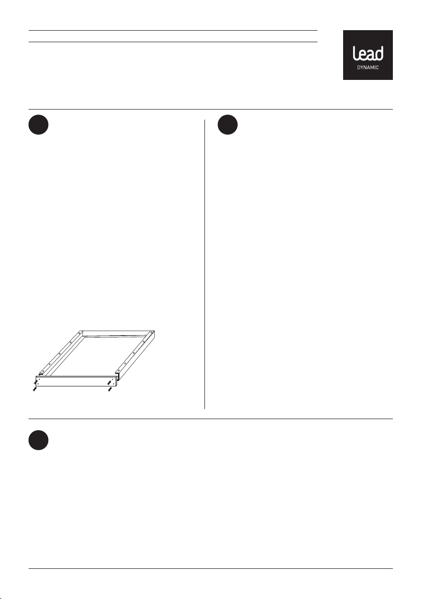
Montage als Anbauleuchte
Montage mit optional erhältlichem PANEL FRAME
PF (Beachte auch die Montageanleitungen des
Zubehörs)
Setze die vier Profile zusammen und verschraube
diese mit je vier Schrauben in den dafür vorgesehenen Löchern an den beiden Endkappen.
Befestige den Rahmen an der Decke. Hierzu musst
Du die für Deine Decke geeigneten Befestigungsmaterialien verwenden. Löse anschließende eine
Endkappe vom Rahmen, stelle den elektrischen
Anschluss her und lege Dein Panel ein.
Verschraube nun wieder die Endkappe mit den vier
Schrauben.
1.4
Montage als abgehängte Leuchte mit
Rahmen
Hierzu benötigst Du zusätzlich zum Rahmen ein
passendes ROPE HANGER SET.
Setze die vier Profile zusammen und verschraube
diese mit je vier Schrauben in den dafür vorgesehenen Löchern an den beiden Endkappen.
Befestige die Montagesockel Deines ROPE HANGER
SETS an der Decke. Hierzu musst Du die für Deine
Decke geeigneten Befestigungsmaterialien verwenden.
Befestige die dafür vorgesehenen Enden Deines
ROPE HANGER SETS am PANEL FRAME.
Löse anschließende eine Endkappe vom Rahmen
und lege Dein Panel ein.
Verschraube nun wieder die Endkappe mit den vier
Schrauben und stelle den elektrischen Anschluss
her.
Montage als abgehängte Leuchte ohne Rahmen
1.5
Beachte auch die Montageanleitungen des Zubehörs.
1. Befestige die Montagesockel Deines ROPE HANGER SETS an der Decke. Hierzu musst Du die für Deine Decke geeigneten Befestigungsmaterialien verwenden.
2. Befestige die Gegenstücke zu Deinem ROPE HANGER SETS am PANEL FRAME in den vorgesehenen Bohrlöchern
mit den beiliegenden Schrauben.
3. Schraube die Endstücke Deines ROPE HANGER SETs an die zuvor befestigten Gegenstücke am Panel.
4. Stelle den elektrischen Anschluss her.
LEAD ENERGY AG Am Stadtbad 37 45219 Essen-Kettwig Irrtümer und Änderungen vorbehalten Informationen / technischer Support: www.lead-energy.com
DEUTSCH
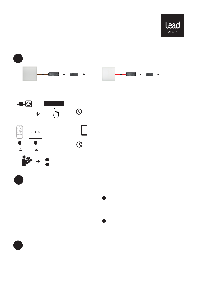
Weiß : kaltweiß
Gelb: kaltweiß
Braun: +
2
Installation
Weiß : kaltweiß
Gelb: kaltweiß
Braun: +
+
WiFi
lernen
A B
Steuerung
3
Zum Steuern eines Produktes aus der LED
DYNAMIC SERIE von LEAD DYNAMIC brauchst Du
entweder ein Smartphone (nicht enthalten) und die
LEAD DYNAMIC APP oder ein optional erhältliches
Produkt zum Steuern (beachte hierzu die Übersicht
am Ende des Abschnitts). Die LEAD DYNAMIC APP
kannst Du kostenlos im APP Store von Apple oder
im Play Store von Google herunterladen. Eine aktuelle Liste mit den unterstützten Betriebssystemen
findest Du unter: www.lead-energy.com
Einstellungen zurücksetzen
4
„learning“
Knopf
A
Fernbedienung
B
Wandcontroller
15 sec.
}
Smartphone
<90 sec.
Braun: +
Rot: roter Farbkanal
Grün: grüner Farbkanal
Blau: blauer Farbkanal
Um die „LERNEN“-Funktion zu starten, verbinde Dein
LED PANEL DYNAMIC mit dem Netz, drücke die „Learning“-Taste auf Deinem WiFi-Controller und befolge die
Installationsanweisungen in der Bedienungsanleitung
Deiner Fernbedienung / Deines Wandcontrollers oder
die Hinweise in der APP. Der gesamte „Lernen“-Vorgang muss innerhalb von 15 Sekunden abgeschlossen
werden. Wenn Du die Leuchte mit der LED DYNAMIC
APP steuern möchtest, hast Du 90 Sekunden Zeit um
den „Lernen“-Vorgang abzuschließen.
Ansonsten benötigst Du einen der folgenden Artikel:
A
DYNAMIC COLOR:
Fernbedienung CDC / Art.-Nr.: 70100006
DYNAMIC WHITE:
Fernbedienung CDW / Art.-Nr.: 70100007
B
DYNAMIC COLOR:
Wandcontroller WCC / Art.-Nr.: 70100015
DYNAMIC WHITE:
Wandcontroller WCW / Art.-Nr.: 70100016
Um alle Einstellungen Deines LED PANEL DYNAMIC zurückzusetzen, halte die „Learning“-Taste auf Deinem WiFi-Controller gedrückt bis Deine Leuchte blinkt (ca. 10 Sekunden).
LEAD ENERGY AG Am Stadtbad 37 45219 Essen-Kettwig Irrtümer und Änderungen vorbehalten Informationen / technischer Support: www.lead-energy.com

ENGLISH
Thank you for choosing a product from LEAD energy
AG. If you would like to get in touch with our service
team, please contact them via our website or by
e-mail.
Intended use Note
ings or install them as surface mounted ceiling lights
or suspended lights using the accessories that are
available separately.
1
Mounting
Note that the WLAN controller for your luminaire
must be accessible for product configuration. You
can also configure your luminaire prior to installation. The settings will be maintained even if the
power supply is disconnected. Make a note of the
SSID and password of the WLAN controller.
Please observe the warnings prior to installation.You can install the PDW and PDC panels in grid ceil-
1.1
You can install your PDC or PDW in grid ceilings by
replacing a ceiling panel with the respective light
panel. The size of the ceiling panel must match that
?
service@lead-energy.com
www.lead-energy.com
Mounting in grid ceilings
1.2
Mounting in suspended ceilings (this type of installation is only possible with PDW panels)
Fix the spring clips provided to your panel using the screws. Make a ceiling cut-out; the size of the cut-out can be
selected from the following list: PDW 30: 289 x 289 mm, PDW 62: 609 x 609 mm, PDW 60: 589 x 289 mm, PDW 120
SLIM: 1189 x 139 mm und PDW 120: 1189 x 289 mm
The cut-out must be extremely precise. The edges of the cut-out must be able to bear the weight of the luminaire.
Connect the power supply in the ceiling. Insert the panel into the cut-out in the ceiling by pressing back the spring
clips. Make sure the panel is locked fully into place.
LEAD ENERGY AG Am Stadtbad 37 45219 Essen-Kettwig Subject to errors and amendments Information / Technical support: www.lead-energy.com

ENGLISH
1.3
Mounting as a surface-mounted light
Installation with optionally available PANEL
FRAME PF (See also installation instructions for
accessories)
Assemble the four profiles and screw them together
using four screws in the holes provided on both end
caps. Attach the frame to the ceiling. You must use
attachment materials that are appropriate for your
ceiling. Loosen an end cap from the frame, connect
to the mains and insert your panel.
Now screw the end cap back on using the four
screws.
1.4
Mounting as suspended light with frame
You will also need a ROPE HANGER SET in addition
to the frame for this.
Assemble the four profiles and screw them
together using four screws in the holes provided
on both end caps. Fix the installation socket of
your ROPE HANGER SET to the ceiling. You must
use fixing materials that are appropriate for your
ceiling for this purpose. Attach the ends of your
ROPE HANGER SET provided for this purpose to the
PANEL FRAME. Loosen an end cap from the frame
and insert your panel.
Now screw the end cap back on using the four
screws and connect to the mains.
Mounting as suspended light without frame
1.5
See also installation instructions for accessories.
1. Fix the installation socket of your ROPE HANGER SET to the ceiling. You must use fixing materials that are appropriate for your ceiling for this purpose.
2. Mount the counterparts to your ROPE HANGER SET on the PANEL FRAME in the drilling holes provided using the
screws enclosed.
3. Screw the end pieces of your ROPE HANGER SET to the previously attached counterparts on the panel.
4. Connect to the mains.
LEAD ENERGY AG Am Stadtbad 37 45219 Essen-Kettwig Subject to errors and amendments Information / Technical support: www.lead-energy.com

ENGLISH
white: cool white
yellow: warm white
brown: +
2
Installation
white: cool white
yellow: warm white
brown: +
+
WiFi
learn
A B
3
Control
To control a product from the LED DYNAMIC SERIES
from LEAD DYNAMIC, you need either a Smartphone (not included) and the LEAD DYNAMIC app
or an optionally available product for controlling
(please note the overview at the end of the section).
You can download the LEAD DYNAMIC app free from
the Apple App Store or the Google Play Store. An
up-to-date list of supported operating systems is
available at: www.lead-energy.com.
4
Reset settings
„learning“
Button
A
Remote Control
B
Wall Controller
15 sec.
}
Smartphone
<90 sec.
brown: +
red: red colour channel
green: green colour channel
blue: blue colour channel
To start the ‘LEARN’ function, connect your LED
PANEL DYNAMIC to the mains, press the ‘Learning’
button on your WiFi controller and follow the installation instructions in the operating manual for your
remote control / wall controller or the instructions in
the app. The ‘learning’ process must be completed
within 15 seconds. If you want to control the luminaire
using the LED DYNAMIC APP, you have 90 seconds to
complete the ‘learning’ process.
Otherwise, you will need one of the following
products:
A
DYNAMIC COLOR:
Remote Control CDC / Product No.: 70100006
DYNAMIC WHITE:
Remote Control CDW / Product No.:70100007
B
DYNAMIC COLOR:
Wall Controller WCC / Product No.: 70100015
DYNAMIC WHITE:
Wall Controller WCW / Product No.: 70100016
To reset all settings on your LED PANEL DYNAMIC, hold down the ‘Reset’ button on your WIFI controller until your
luminaire flashes (approx. 10 seconds).
LEAD ENERGY AG Am Stadtbad 37 45219 Essen-Kettwig Subject to errors and amendments Information / Technical support: www.lead-energy.com

FRANÇAIS
Merci d’avoir choisi un produit LEAD energy AG. Si
vous avez besoin de notre SAV, vous pouvez nous
joindre sur notre page d’accueil et par e-mail à
l’adresse suivante:
Utilisation conforme Remarque
Vous pouvez monter les panneaux PDW et PDC dans
des plafonds à grille ou les poser comme montage
en saillie au plafond ou luminaire suspendu à l’aide
d’accessoires disponibles en option.
1
Montage
Veuillez à ce que le contrôleur WiFi de votre lampe
soit accessible pour la configuration du produit.
Vous pouvez aussi configurer votre lampe avant le
montage. Les réglages restent encore disponibles
si vous coupez l’alimentation électrique. Notez le
numéro SSID et le mot de passe du contrôleur WiFi.
Avant l‘installation, veuillez observer impérativement
les avertissements énoncés!
1.1
Vous pouvez monter votre panneau PDC ou PDW dans
des plafonds à grille, en remplaçant une dalle de plafond par le panneau. Ce faisant, la taille de la dalle de
plafond doit correspondre à celle du panneau.
?
service@lead-energy.com
www.lead-energy.com
Montage dans les plafonds à grille
1.2
Le montage en faux plafonds (ce type de montage est uniquement possible avec les panneaux PDW)
Vissez les pinces à ressort fournies avec les vis sur votre panneau. Réalisez une découpe de plafond. Vous pouvez
déduire la taille de la découpe de la liste suivante: PDW 30: 289 x 289 mm, PDW 62: 609 x 609 mm, PDW 60: 589 x
289 mm, PDW 120 SLIM: 1189 x 139 mm und PDW 120: 1189 x 289 mm
Vous devez réaliser la découpe avec beaucoup de précision. Les bords de la découpe doivent pouvoir supporter
le poids du luminaire.
Effectuez le raccordement électrique du cordon d’alimentation dans le plafond. Placez le panneau dans la découpe
de plafond, en repoussant les pinces à ressort. Assurez-vous que le panneau est complètement enclenché.
LEAD ENERGY AG Am Stadtbad 37 45219 Essen-Kettwig Sous réserves d‘erreurs ou modifications Informations/assistance techniquecom: www.lead-energy.com
 Loading...