

Page 1
2R-II™
O
PERATOR’S MANUAL
Page 2

Page 3
2R-II™
O
PERATOR’S MANUAL
Page 4

Liability
Labrie Enviroquip Group assumes no liability for any incidental, consequential, or other liability that
might result from the use of the information contained in this document.
All risks and damages, incidental or otherwise, arising from the use or misuse of the information
contained herein are entirely the responsibility of the user.
Although careful precaution has been taken in the preparation of this document, Labrie Enviroquip
Group assumes no responsibility for errors or omissions.
January 2015
Page 5

Page 6

Page 7

Table of Contents
Liability ........................................................................................ ii
Table of Contents ........................................................................ v
Introduction ................................................................................ 1
Introducing the 2R-II™ .................................................................................................................................................................... 1
Product Overview ...................................................................................................................................................................... 1
To Contact Labrie Plus .................................................................................................................................................................... 5
In the U.S. ...................................................................................................................................................................................... 5
In Canada ...................................................................................................................................................................................... 5
Safety Precautions ...................................................................... 7
General ................................................................................................................................................................................................. 7
Conventions ....................................................................................................................................................................................... 8
Basic Safety Notions ........................................................................................................................................................................ 8
Responsibilities .................................................................................................................................................................................. 9
Employer Responsibilities ...................................................................................................................................................... 9
Employee Responsibilities ...................................................................................................................................................... 9
Things to Do .................................................................................................................................................................................... 10
Things to Avoid .............................................................................................................................................................................. 10
Safety Precautions ......................................................................................................................................................................... 10
Prior to Start-Up ...................................................................................................................................................................... 10
General Operation .................................................................................................................................................................. 11
Hydraulics .................................................................................................................................................................................. 14
Fire Protection ......................................................................................................................................................................... 14
Housekeeping .......................................................................................................................................................................... 15
Safety and Informative Decals .................................................................................................................................................. 16
Decals on Body ........................................................................................................................................................................ 17
Decals on Tailgate .................................................................................................................................................................. 24
Decals inside Cab .................................................................................................................................................................... 28
Safety Features ............................................................................................................................................................................... 31
Back Up Alarm .......................................................................................................................................................................... 31
Tailgate Safety Props ............................................................................................................................................................. 31
Camera System ........................................................................................................................................................................ 36
Tailgate Open Proximity Switch Test .............................................................................................................................. 37
Locking Out and Tagging Out the Vehicle ........................................................................................................................... 38
Shutting Down the Vehicle ........................................................................................................................................................ 40
Prior to Start Up .............................................................................................................................................................................. 40
Controls, Indicators and Processes .......................................... 43
In-Cab Controls ............................................................................................................................................................................... 43
Parking Brake ........................................................................................................................................................................... 43
Pump Switch ............................................................................................................................................................................ 44
ENGINE SPEED-UP Switch ......................................................................................................................................................... 44
AUTO-NEUTRAL Switch (optional) ........................................................................................................................................ 45
REAR WORK LIGHT Switch (optional) .................................................................................................................................... 45
FRONT WORK LIGHT Switch (optional) ................................................................................................................................. 46
HOPPER LIGHT Switch (optional) ........................................................................................................................................... 46
FLASHING LIGHT Switch (optional) ........................................................................................................................................ 47
STROBE LIGHT Switch (optional) ........................................................................................................................................... 47
Indicators .......................................................................................................................................................................................... 48
Page 8

vi Table of Contents
TAILGATE OPEN Light ................................................................................................................................................................. 48
Outside Controls ............................................................................................................................................................................ 49
Engine Speed-Up Push Button ........................................................................................................................................... 49
Front Control Valve ................................................................................................................................................................ 49
Ejection (Pushout) Lever ....................................................................................................................................................... 49
Tailgate Lever ........................................................................................................................................................................... 49
Tailgate Clamps ....................................................................................................................................................................... 50
Hydraulic Tailgate-Locking Mechanism Buttons (optional) .................................................................................... 50
Driver Signal Push Buttons .................................................................................................................................................. 50
Packer and Carrier Panel Levers ......................................................................................................................................... 51
Container Handling Control Levers (optional) ............................................................................................................. 52
Tipper Lever (optional) ......................................................................................................................................................... 52
Terms You Will Need To Know .................................................................................................................................................. 53
Container Attachment .......................................................................................................................................................... 53
Container Handling Systems .............................................................................................................................................. 54
Hook ............................................................................................................................................................................................. 55
Container ................................................................................................................................................................................... 55
Container Attachment .......................................................................................................................................................... 55
Winch ........................................................................................................................................................................................... 56
Container Lifting Cylinder (CLC) ........................................................................................................................................ 56
Container Push Bar (CPB) ..................................................................................................................................................... 57
Other Terms You Will Need To Know ..................................................................................................................................... 57
Container Handling Process ....................................................................................................................................................... 58
Attaching ................................................................................................................................................................................... 58
Dumping .................................................................................................................................................................................... 59
Releasing .................................................................................................................................................................................... 59
Waste Handling Process .............................................................................................................................................................. 59
Loading ....................................................................................................................................................................................... 59
Packing ....................................................................................................................................................................................... 60
Unloading .................................................................................................................................................................................. 61
Operating the 2R-II™ ................................................................. 63
Pre-Operating Walk-Around Inspection ................................................................................................................................ 63
Walk-Around Inspection Checklist ................................................................................................................................... 66
Inspection Sheet ...................................................................................................................................................................... 67
Operating Instructions ................................................................................................................................................................. 68
Starting Up ................................................................................................................................................................................ 68
Positioning the Pushout Panel ........................................................................................................................................... 68
Loading the Hopper ............................................................................................................................................................... 69
Attaching a Container to the Tailgate ............................................................................................................................. 69
Using a Winch or a Container Lifting Cylinder ............................................................................................................. 71
Using a Container Push Bar (CPB) ..................................................................................................................................... 73
Packing the Load ..................................................................................................................................................................... 73
Pushout Panel Operation during Packing ..................................................................................................................... 75
Releasing the Container ....................................................................................................................................................... 75
Unloading at Dumpsite ........................................................................................................................................................ 76
Lifting the Tailgate .................................................................................................................................................................. 77
Ejecting the Load .................................................................................................................................................................... 77
Lowering the Tailgate ........................................................................................................................................................... 79
Shutting Down the Truck ..................................................................................................................................................... 79
Page 9

1
Introduction
The purpose of this manual is to introduce operators
to the operational procedures of the 2R-II™ rear-loader
garbage truck. For information regarding maintenance
procedures, refer to the related 2R-II™ Maintenance
Manual.
Introducing the 2R-II™
2R-II™ units are rear-load refuse collection vehicles
used for residential, commercial and demolition
garbage pick-ups. Once the body is full, all its content
is unloaded at a waste management landfill or other
appropriate site (e.g. transfer station, incinerator,
recycling station). These units are designed to improve
every aspect of your garbage collection operation, and
they use a series of hydraulic, mechanical, and
electrical systems to perform their work routine.
Depending on the type of collection for which it is
intended, the 2R-II™ is offered in two main collection
configurations: semi-automated and manual.
Vehicles destined for semi-automated collection are
equipped with a cart tipper, and vehicles destined for
manual collection benefit from the lowered hopper
load sill.
All other major options and body configurations are
explained in the following pages.
Product Overview
The 2R-II™ is a tough, reliable and user-friendly
collection truck. It has everything you need to perform
your work efficiently: a large hopper, fast packing
cycles, an efficient open-and-eject process and great
versatility for use not only in residential and
commercial waste collection but also in demolition
waste collection.
Page 10
2 Introduction
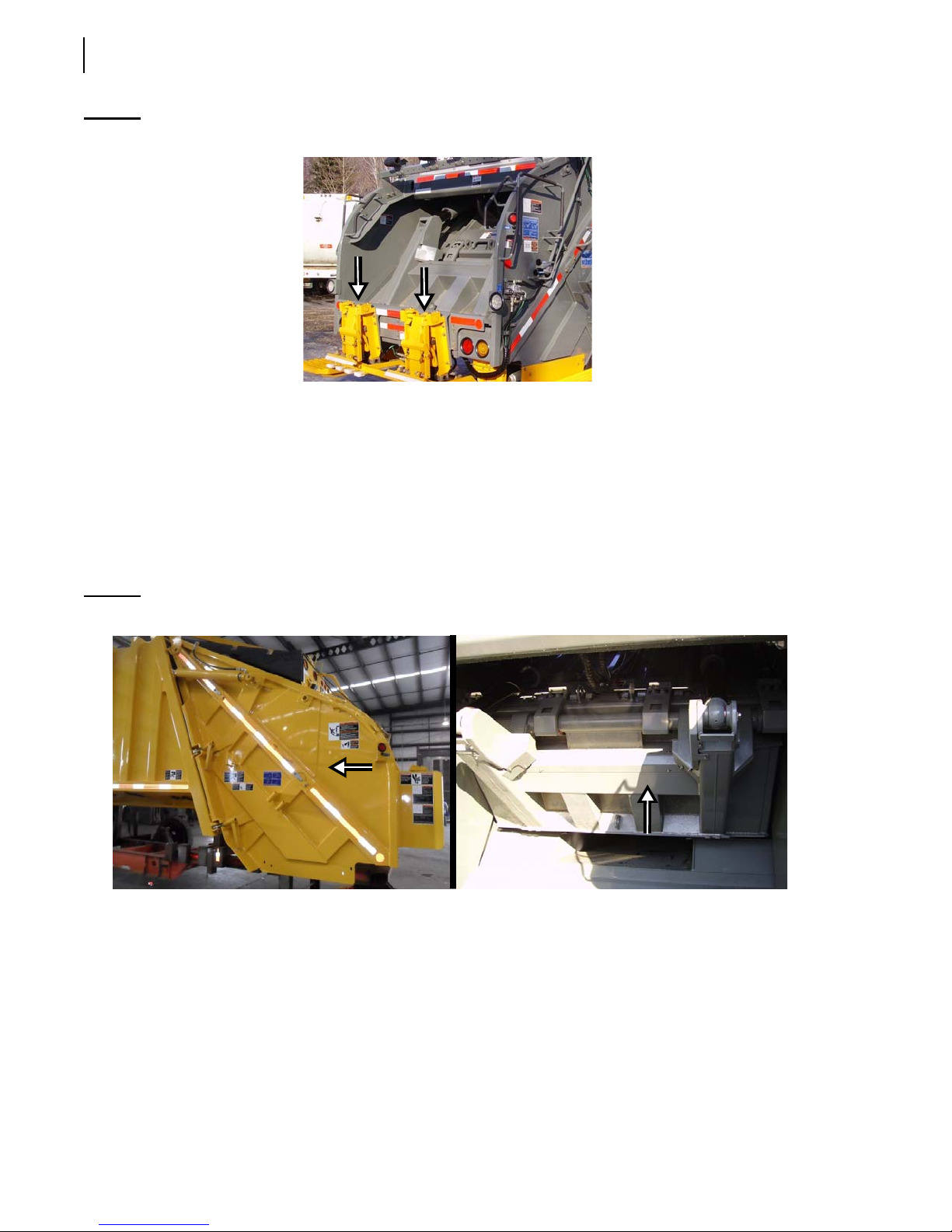
Figure 1-1
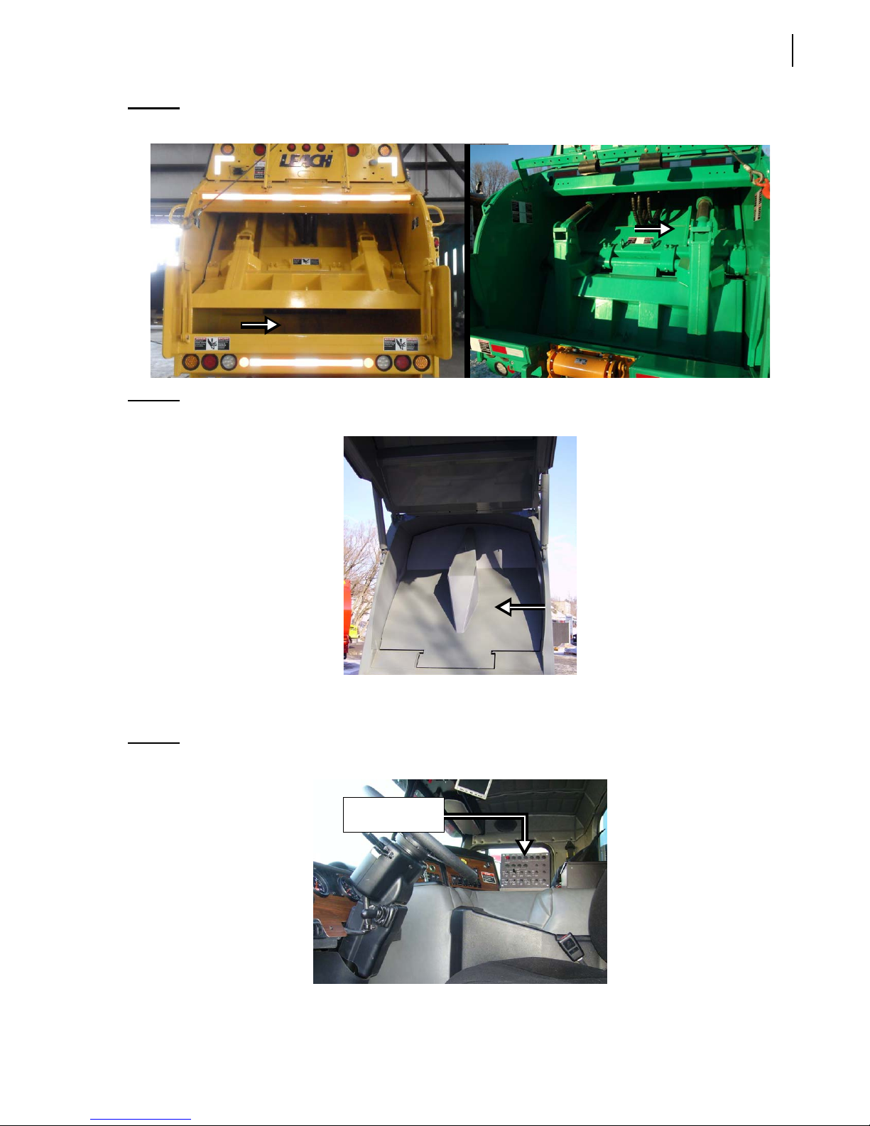
Body’s main components are the hopper (see Figure 1-3), the packer (see Figure 1-2), the tailgate
(see Figure 1-2), the pushout panel (see Figure 1-4), and the carrier panel (see Figure 1-3).
Some trucks may be equipped with one or two cart tippers (see Figure 1-1). Or they may be equipped
with a push bar. If the latter is installed, a reeving cylinder or winch is provided.
The hopper is the area of the body where the refuse is dumped. The packer is the piece of equipment
that pushes the refuse into the body. The pushout (or ejection) panel is the piece of equipment that is
used to eject garbage at landfill sites. The tailgate is the rear pivotal door that prevents refuse from
exiting the body during collection. At landfill, the tailgate is raised to enable discharge of the refuse.
Cart tippers
Figure 1-2
Tailgate (left); Packer (right)
Page 11
Introduction 3
Figure 1-3
Figure 1-4
Hopper (left); Carrier panel (right)
Pushout panel
In the cab, you will find the console on which the engine speed-up switch and the hydraulic pump
switch are located (see Figure 1-5).
Figure 1-5
2R-II™ cab
Console
Page 12
4 Introduction
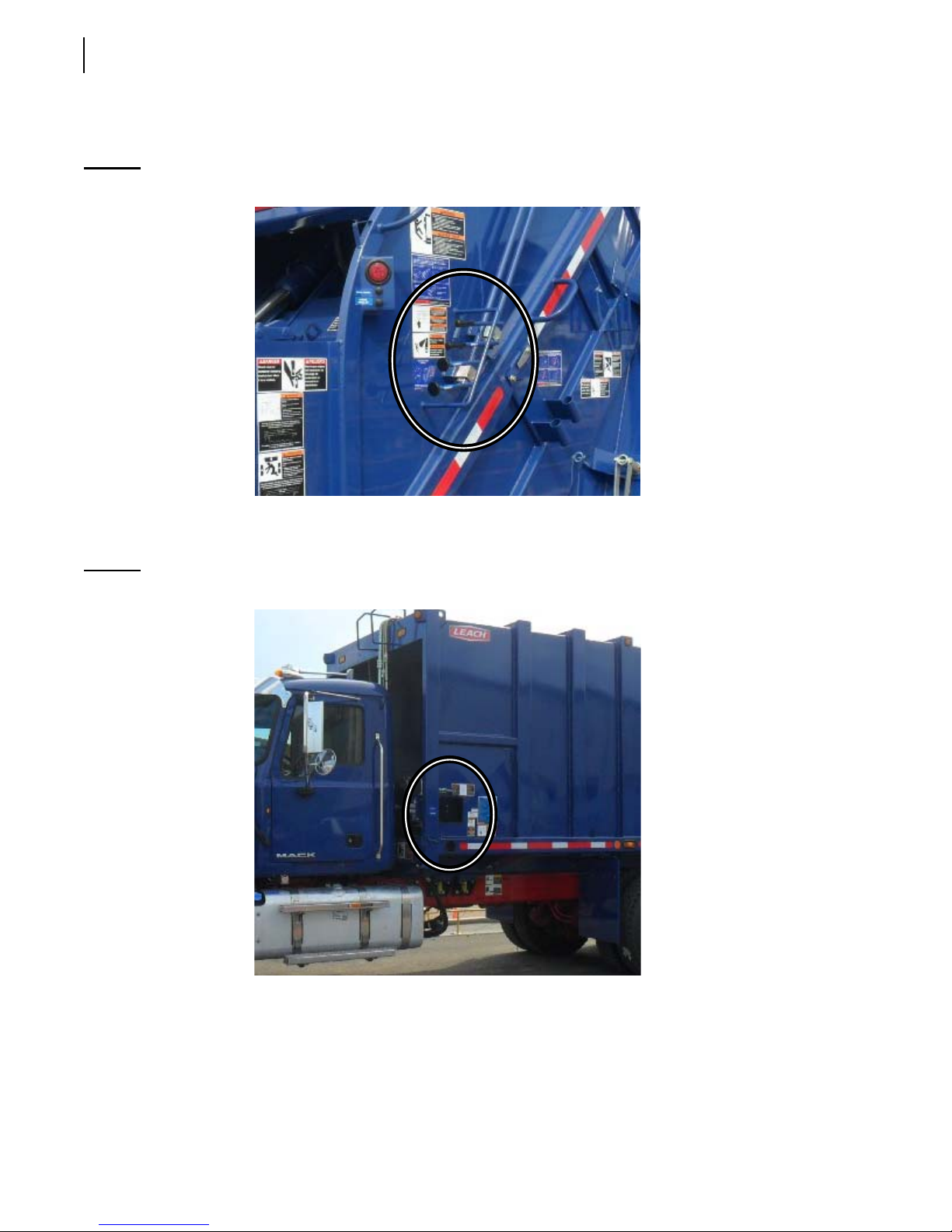
Operating controls for the packer, carrier panel, and container handling system are located on the
right-hand side of the tailgate.
Figure 1-6
Operating controls for the pushout panel and tailgate are located on the left-hand side of the body,
not far from the cab.
Figure 1-7
Operating controls (packer, carrier panel, container handling system)
Pushout panel and tailgate operating controls
Page 13

To Contact Labrie Plus
In the U.S.
Address: 1981 W. Snell Road
Oshkosh, WI 54904
Toll Free: 1-800-231-2771
Telephone: 1-920-233-2770
General Fax: 1-920-232-2496
Sales Fax: 1-920-232-2498
Parts and warranty: During business hours, 7:00 AM to 7:00 PM Central Standard Time
Technical Support Service: Available 24 hours
Introduction 5
In Canada
Address: 175 Route du Pont
St-Nicolas, QC G7A 2T3
Toll Free: 1-877-831-8250
Telephone: 1-418-831-8250
Service Fax: 1-418-831-1673
Parts Fax: 1-418-831-7561
Parts and warranty: During business hours, 8:00 AM to 5:00 PM Eastern Standard Time
Technical Support Service: Available 24 hours
Website: www.labriegroup.com
E-mail: [email protected]
IMPORTANT: For technical support and parts ordering, the serial number of your vehicle is required. Therefore,
Labrie Enviroquip Group recommends to keep record of the information found on the VIN plate,
which is located in the cab.
Page 14

6 Introduction
Page 15

2
Safety Precautions
General
IMPORTANT: This manual contains safety information that could
prevent accidents. Read and thoroughly understand
it before operating the unit.
To us all at Labrie Enviroquip Group, the safety of
vehicle operators is one area of great importance.
This vehicle was built in accordance with the American
National Standards Institute (
Mobile Refuse Collection and Compaction
Equipment – Safety Requirements,
1999.
Also, since 2R-II™ vehicles are heavy duty pieces of
equipment, they require that a certain number of safety
precautions be taken.
The 2R-II™ has been designed with the operator in
mind. However, as with any industrial machinery,
especially those that are large and apply forces through
hydraulic pressures, the ultimate responsibility for
safety rests with you, the operator.
ANSI) standard for
ANSI Z245.1 –
An alert, conscientious attitude, and observance of all
known safe operating practices are the best ways to
prevent accidents. It is the operator’s responsibility to
be familiar with, and ensure that operation is in
accordance with safety requirements and codes
including all applicable Occupational Safety & Health
Act (
OSHA) and ANSI regulations.
Additional safety precautions, along with all the
necessary instructions and conventions, are presented
in the following pages.
Page 16
8 Safety Precautions
Conventions
Danger!
Warning!
Caution!
The word “NOTE” is also used throughout the manual. It precedes information that provides special
emphasis or clarification on a specific operation or procedure.
Indicates a hazardous situation which, if not avoided, will result in serious injury or death.
Indicates a hazardous situation which, if not avoided, could result in serious injury or
death.
Indicates a hazardous situation which, if not avoided, may result in minor or moderate
injury or property/product damage.
Basic Safety Notions
The following safety notions are related to the use of the 2R-II™. It is important to point out that the
safe use of the vehicle remains the user’s responsibility. He must heed all safety notions explained in
this manual and on the decals affixed to the vehicle.
Danger!
Danger!
Warning!
Always be aware of the vehicle’s surroundings to make sure that no pedestrians,
passersby, bystanders, or other people or vehicles are in any way exposed to any danger
caused by the use of the 2R-II™.
Never get in the hopper area when the engine is running.
Only authorized personnel may do so following a lockout/tagout procedure (see Locking
Out and Tagging Out the Vehicle on page 38).
Always wear safety glasses, gloves and proper footwear while collecting waste. Explosive
objects, pressurized cans, and fluorescent tubes can be present and pose a danger. Be
alert!
Page 17

Responsibilities
Safety is everybody’s responsibility. Both employer and employee must play their part to ensure the
safety of the operator, the vehicle, and its immediate surroundings.
Employer Responsibilities
It is the responsibility of the employer:
To ensure that employees are qualified for operating the vehicle and its equipment, and that they
all take safety measures before using them.
To properly maintain all mobile equipment to meet all provincial/state and federal safety
standards.
To supply adequate instructions and training for the safe use of the vehicle and its equipment
before assigning an employee to such vehicle/equipment.
To keep the vehicle maintained and properly adjusted to meet the manufacturer’s standards and
recommendations. For help or for more information, please contact the manufacturer or any of its
authorized representatives.
Safety Precautions 9
To keep records of all vehicle breakdowns and malfunctions, as well as any inspection and
maintenance.
To ensure that all failures or malfunctions that may be affecting the safe use of the vehicle are
repaired before the vehicle is put back into operation.
To meet the appropriate lighting requirements for night shift work (if permitted).
To regularly accompany the vehicle operator and take measures to ensure the smooth and safe
operation of the vehicle.
To make sure that the backup alarm works properly when the vehicle is in reverse.
To take necessary measures to correct any damage or malfunction reported by any employee.
To establish a “lockout/tagout” procedure and ensure its application any time inspection, repair
or maintenance is performed on the vehicle, regardless of whether it takes place on the road or in
the garage.
Employee Responsibilities
It is the responsibility of the employee:
To enforce all safety measures to meet the requirements established by the employer.
To operate the 2R-II™ only after having received proper instructions and training.
To perform routine daily unit inspections.
To make sure that nobody is near the vehicle before activating any of the controls, and to be
prepared to stop at any indication of possible danger.
To immediately report any damage or malfunction of the vehicle to the employer or supervisor.
To know where to get assistance in the event of an emergency.
IMPORTANT: Do not use damaged equipment.
Page 18

10 Safety Precautions
Things to Do
Inspect the body and all systems at the beginning of each day.
Make sure that the area is clear of any people or possible obstructions.
IMPORTANT: Be extremely cautious in areas where small children may be present.
Wear safety glasses and footwear, gloves, and any other safety equipment when loading and
packing refuse.
Check mirrors, windows, lights, and monitor equipment are clean and adjusted properly.
Check for explosive trash (e.g. television sets, paint cans, fluorescent light tubes, etc.).
Use caution when driving with an unevenly distributed load.
Inspect for overhead hazards (e.g. power lines) prior to raising tailgate.
Always use the tailgate safety prop before entering the area between the main body and the
tailgate.
Obey all warning and operation stickers.
Things to Avoid
Do not operate any vehicle while under the influence of alcohol, narcotics or other intoxicants.
Do not talk on a cell phone or listen to loud music while driving.
Do not wear jewelry or loose clothing.
Do not leave the vehicle before it is brought to a complete stop and work brake or parking brake is
applied.
Do not enter the hopper or main body unless the engine is shut off, the key is removed and there is
an out-of-service tag on the steering wheel (see Locking Out and Tagging Out the Vehicle on
page 38).
Do not drive with the tailgate fully open unless it is to unload refuse at the landfill.
Safety Precautions
Danger!
Operators must adhere to the following safety precautions at all times. Failure to do so
may result in vehicle and/or property damage, personal injury, or even death.
Prior to Start-Up
Never operate machinery while wearing jewelry or loose clothing. These items may become
caught by or entangled in the machinery causing serious injury. Wear proper safety equipment as
required by your employer.
Page 19

Safety Precautions 11
Never operate machinery while under the influence of alcohol, narcotics or other mood altering
substances. Workers who operate machinery while under the influence are a hazard to themselves
and others.
Perform a pre-operation “walk around” inspection of the truck chassis in accordance with the
chassis manufacturer’s guidelines. Perform a “walk around” inspection of the refuse packer. Never
start or operate any equipment found to have malfunctions.
• Report any malfunctions immediately to the proper authorities.
• Prior to leaving any malfunctioning unit, the parking brakes must be set, the PTO system
disengaged, the engine turned off, the ignition key removed, and using a nonreusable fastening
device, place a sign on the steering wheel indicating the unit is inoperative. For more
information, see Locking Out and Tagging Out the Vehicle on page 38.
Proper servicing requires specialized tools and procedures. Service must be performed by
authorized personnel only following procedures in the 2R-II™ Maintenance Manual.
Walk completely around the vehicle to make sure all persons and obstructions are clear before
starting the unit.
The container handling system is a critical component of the unit. Use only the proper
replacement parts.
Inspect all hooks, chains and cables daily to ensure serviceable condition. Replace damaged or
worn parts.
Before operating the vehicle the driver must be thoroughly familiar with the employer’s safety
program concerning traffic rules, warning devices and hand signals.
Be sure to know where to get assistance in the event of an emergency.
Know your machine. Know the location and function of all controls, gauges, instruments and
protective devices.
Should the height of a refuse collection vehicle be altered by installing a container handling
system, be sure the overall height is rechecked and overall height plus 3 inches is noted on the
decals.
General Operation
It is the employer’s responsibility to ensure that only qualified employees are assigned to operate
this vehicle.
It is the operator’s responsibility to ensure that operation of the unit is in accordance with the
guidelines contained in the Operator’s manual and in accordance with all applicable codes
including Occupational Safety and Health Act (OSHA) and American National Standards
Institute (ANSI) regulations.
Do not attempt to operate this equipment without proper training.
Read and make sure that you fully understand this manual and all safety decals before operating
this vehicle. Maintenance personnel must also read and understand the Maintenance Manual for
this vehicle. In case of doubt, ask a supervisor for clarifications.
Before every work day, inspect the body, the packing system, and any system that might
compromise public and/or operator safety.
Verify that the accelerator pedal, the steering wheel, mirrors, brakes, and turn signals are in good
working order.
Page 20

12 Safety Precautions
Move the vehicle as slowly as possible without stalling when traveling in reverse.
Always make sure the area behind the unit is clear before traveling in reverse.
Do not travel in reverse for distances greater than those dictated by local ordinances. If reverse
travel exceeds 10 feet, use a “spotter” or move the vehicle in 10 foot increments only, and then
check to make sure the area behind the unit is clear between increments.
Do not attempt to dislodge any material above waist level unless wearing eye protection such as
“approved” side shielded safety glasses or a full face shield.
Never use the unit to push or tow another vehicle.
Never unload uphill or against a pile of refuse or into the bank of a hill.
Never place head, body, fingers or any limbs into a scissors point or pinch point on the equipment.
Before operating the vehicle the driver must be thoroughly familiar with the employer’s safety
program concerning traffic rules, warning devices and hand signals.
Know where to get assistance in the event of an emergency.
Know your machine. Know the location and function of all controls, gauges, instruments and
protective devices.
Do not operate this vehicle if there are any signs of damage or incomplete repairs.
Report any doubts that you might have and any safety service requirements regarding this vehicle
to a supervisor.
When removing nylon locknuts, always replace them by new ones.
Start the engine following the manufacturer’s recommended procedure.
Wear your seat belt.
When driving the vehicle, keep both hands on the steering wheel at all times.
Never drive this vehicle with the tailgate unlocked.
Always set the parking brake before leaving the cab.
When the vehicle is parked, the parking brake must be applied.
Turn on appropriate warning lights, put on a safety vest, protective glasses and protective shoes.
All service opening covers and access doors must be maintained and latched in place while
operating equipment.
Ensure all co-workers are in view before operating or moving any controls or the unit.
Ensure that there is sufficient overhead clearance before operating the unit.
Ride only in the cab or on riding platforms designed for that purpose. Riding steps shall not be
used when speeds are expected to exceed 10 mph (16 km) or when distance traveled without
stopping will exceed 2/10 of one mile. Do not get on/off riding step when vehicle is in motion.
Never allow anyone to ride on the steps when the vehicle is backing up.
Stop the vehicle immediately if warning lights for the
TAILGATE AJAR system come on.
Never use controls or hoses for hand holds when getting on/off. Controls and hoses are movable.
They do not provide proper support and may cause accidental equipment movement.
Make sure the backup alarm is working properly.
Always ensure that all persons are clear before raising or lowering the tailgate. It is the operator’s
responsibility to warn all persons not to stand or cross under a raised tailgate.
Page 21

Safety Precautions 13
Do not move the vehicle with the tailgate raised except during unloading and then only as
necessary to clear the load before lowering.
Stand clear when the tailgate is being raised or lowered and during the unloading cycle. If it is
necessary to manually clear debris from the hopper, use a long metal probe and DO NOT stand
under the tailgate.
Never load the hopper above the loading sill.
Never allow material to extend outside of the hopper when packing.
Allow the packer panel control lever and carrier panel control lever to shift back automatically.
To avoid possible bodily injury or equipment damage, lower the tailgate slowly.
Never enter the body unless the pushout panel clamp or the telescopic ejection system cylinder is
released, PTO disengaged and ignition key removed and placed in your pocket. For more
information, see Locking Out and Tagging Out the Vehicle on page 38.
Do not attempt to load refuse into the hopper after the packing cycle has begun. The packer panel
must be in the “home” position and stopped before loading the hopper.
The speed-up switch on the console must be “OFF” between pickups or when parked. This
prevents inadvertent engine speed-up if the tailgate carrier panel control lever is shifted.
The tailgate clamps must be tightened securely before starting to load.
Do not step on the throttle pedal while the speed-up system is engaged.
Vehicles with automatic transmission require the shift lever to be in gear to engage the PTO and
then shifted to neutral to activate the PTO/pump.
Never use a rear loader to transport a container.
Follow all safety directions listed in the refuse body Operator and Maintenance Manual under
SAFETY PRECAUTIONS.
Never use container handling chains or cable for towing or pulling.
When not handling containers, keep the container attachment closed and latched.
Do not operate the rear loader’s packing mechanism with a container off the ground.
If it is necessary to manually free debris from the container, use a long metal probe while the
container is on the ground, and DO NOT place yourself between the container and the packer
body.
Secure the drum winch or reeving cylinder hook to the tailgate and take up the excess slack when
not in use.
Never hold the hook on an attachment point while taking up slack.
Take up excess cable slack before moving the vehicle.
Check overhead clearance before dumping a container.
Do not move the vehicle with a container attached.
Always set the vehicle parking brake before attaching or lifting a container.
Never lift a container which is non-compatible with the Leach container attachment.
Never lift a container without first latching both container latch arms.
Raise the container with a smooth even movement. Do not bounce the container.
Do not slam the container against the packer tailgate or bump bar.
Page 22

14 Safety Precautions
Do not attach the hook to any lift point which will not be completely encircled by the hook with
the safety latch closed. Do not remove the hook safety latch.
Read and obey all container decals issued by the container manufacturer.
Read and follow container manufacturer’s information on accepted use practices.
Do not attempt to lift overloaded containers.
Center the container on the attachment.
All containers should be inspected for serviceability and repaired if not in safe, usable condition.
Do not use non-standard or damaged trunnion bar.
Never cross under a raised container.
Stand clear when dumping containers.
Before attempting to lift a container below 32 °F (0 ºC) make sure it is not frozen to the ground.
When using an eye type container attachment point, the base of the hook must be positioned to
lift on the inside of the eye.
Place the container on a flat, level surface.
Do not get into the hopper compartment or try to repair anything on the packer when it is moving
or when the hydraulic pump is still running. Personnel authorized to get into the hopper must first
lock out and tag out the vehicle, as required by the employer. For more information, see Locking
Out and Tagging Out the Vehicle on page 38.
Hydraulics
Hydraulic fluid operates under high temperatures. Avoid contact with piping, hoses or cylinders
to prevent burns.
Never use hands to check for leaks. Hydraulic fluid escaping under pressure may cause injury.
In case of injury seek proper medical treatment immediately.
Fire Protection
Anytime a loaded vehicle is brought inside a garage, fire extinguishers shall be close at hand.
The employer must inform employees of an appropriate place to unload the body near the
maintenance facility (preferably away from traffic, surface drains, and ditches).
Keep a fire extinguisher accessible at all times.
Never use lighted smoking materials, open flame or sparks around when working with flammable
materials such as fuel tanks or storage batteries.
Never have an open flame as a light source.
Page 23
Safety Precautions 15
Never load ashes or other materials which might be smoldering. These materials could ignite
refuse in the packer body.
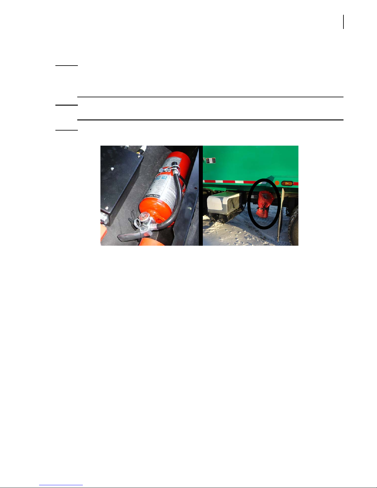
NOTE: 2R-II™ vehicles are equipped with a 5-lb fire extinguisher, which is located inside the cab. A 20-
lb fire extinguisher may also be installed as an option. Each fire extinguisher must be checked
regularly by qualified personnel.
NOTE: A first aid kit, a flare kit and a triangle kit are provided with the truck.
Figure 2-1
5-lb fire extinguisher (left); optional 20-lb fire extinguisher (right)
Housekeeping
Good housekeeping habits are a major factor in accident prevention.
Keep handrails and steps clean and free of grease or debris.
Do not store brooms or other equipment where they could inadvertently activate the packer
controls.
Rubbish, scrap paper and litter are highly combustible. Such material should be stored in metal
containers entirely clear of sparks and flames.
Clean all lights and safety decals so you and the surrounding pedestrians and drivers will be aware
of the truck at all times.
Ensure that the equipment works properly by removing any compacted garbage in the packer area
after each body unloading.
If you need to clean debris from the edges of the tailgate, use a pole while standing to the side.
If installed, use the drain under the curbside of the tailgate to let water and other liquids out of the
tailgate.
Page 24

16 Safety Precautions
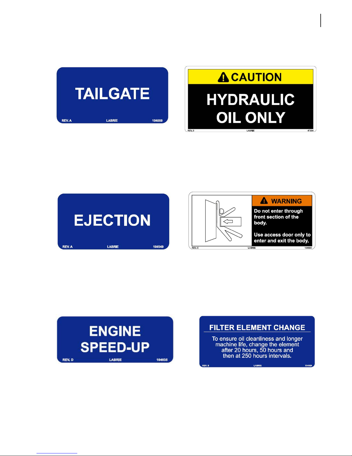
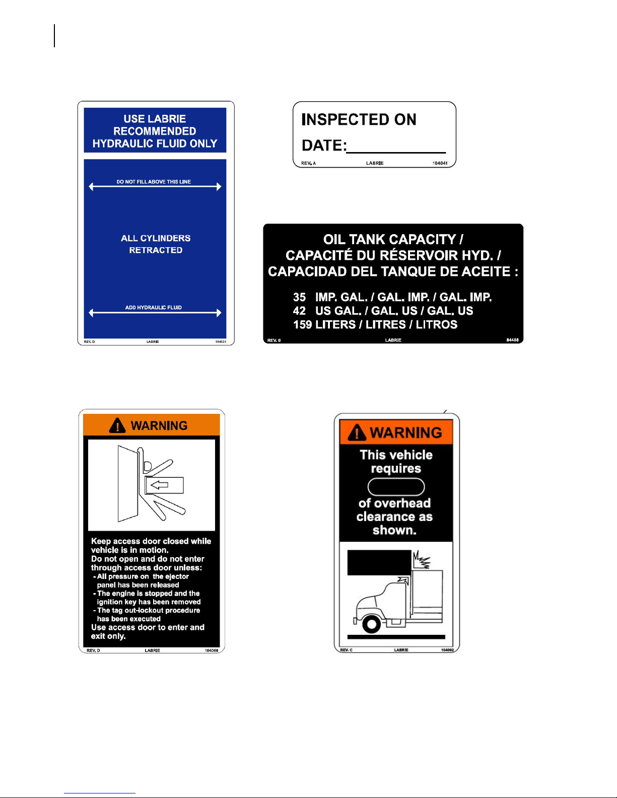
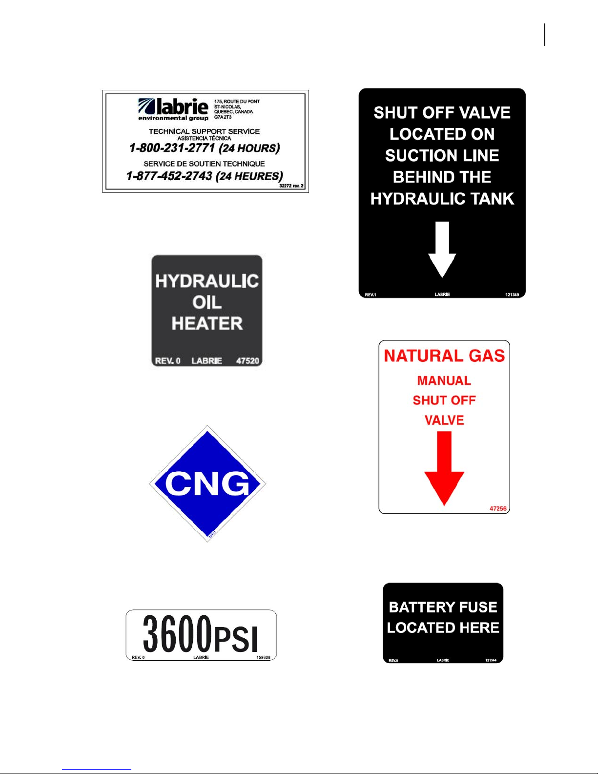
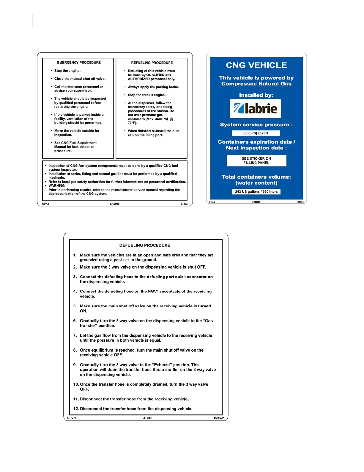
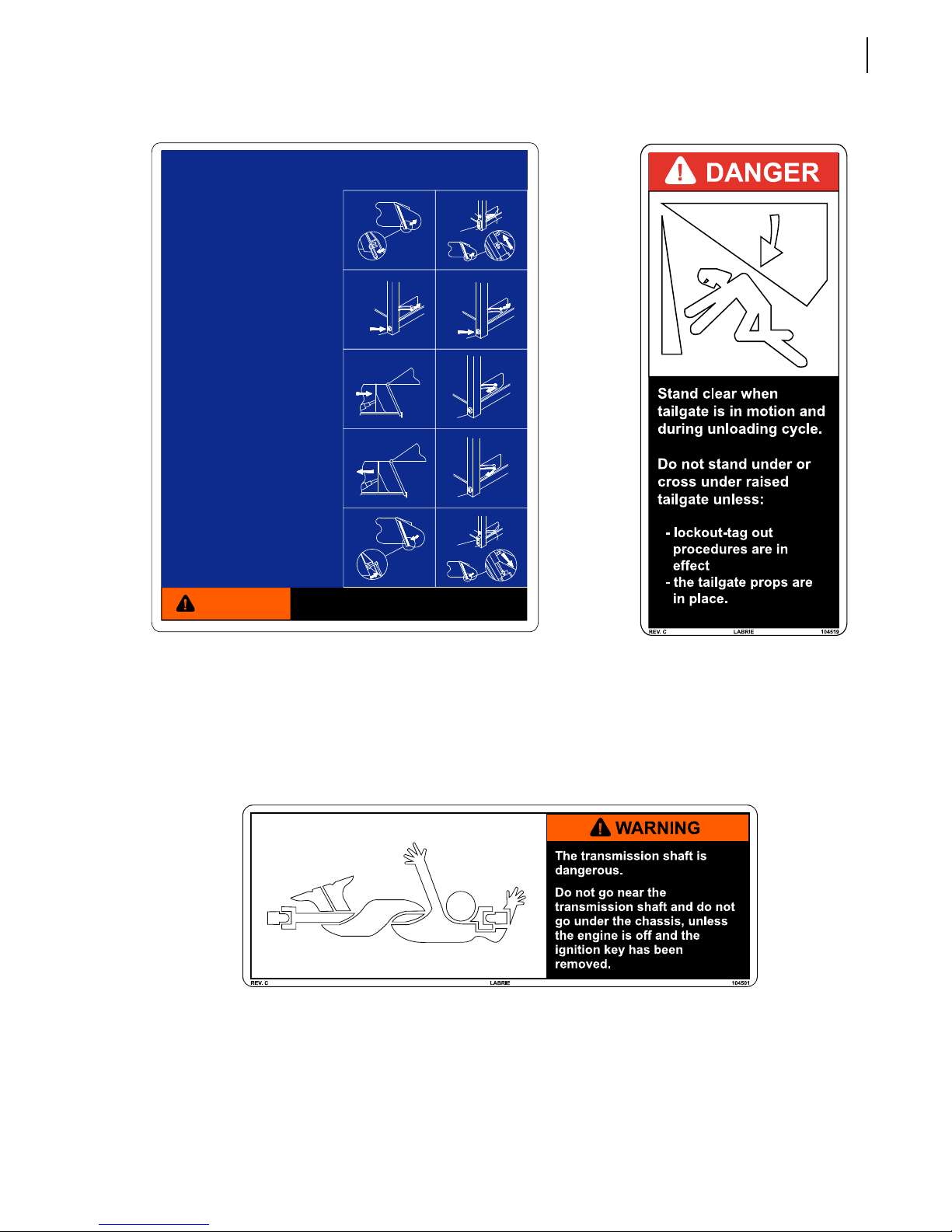
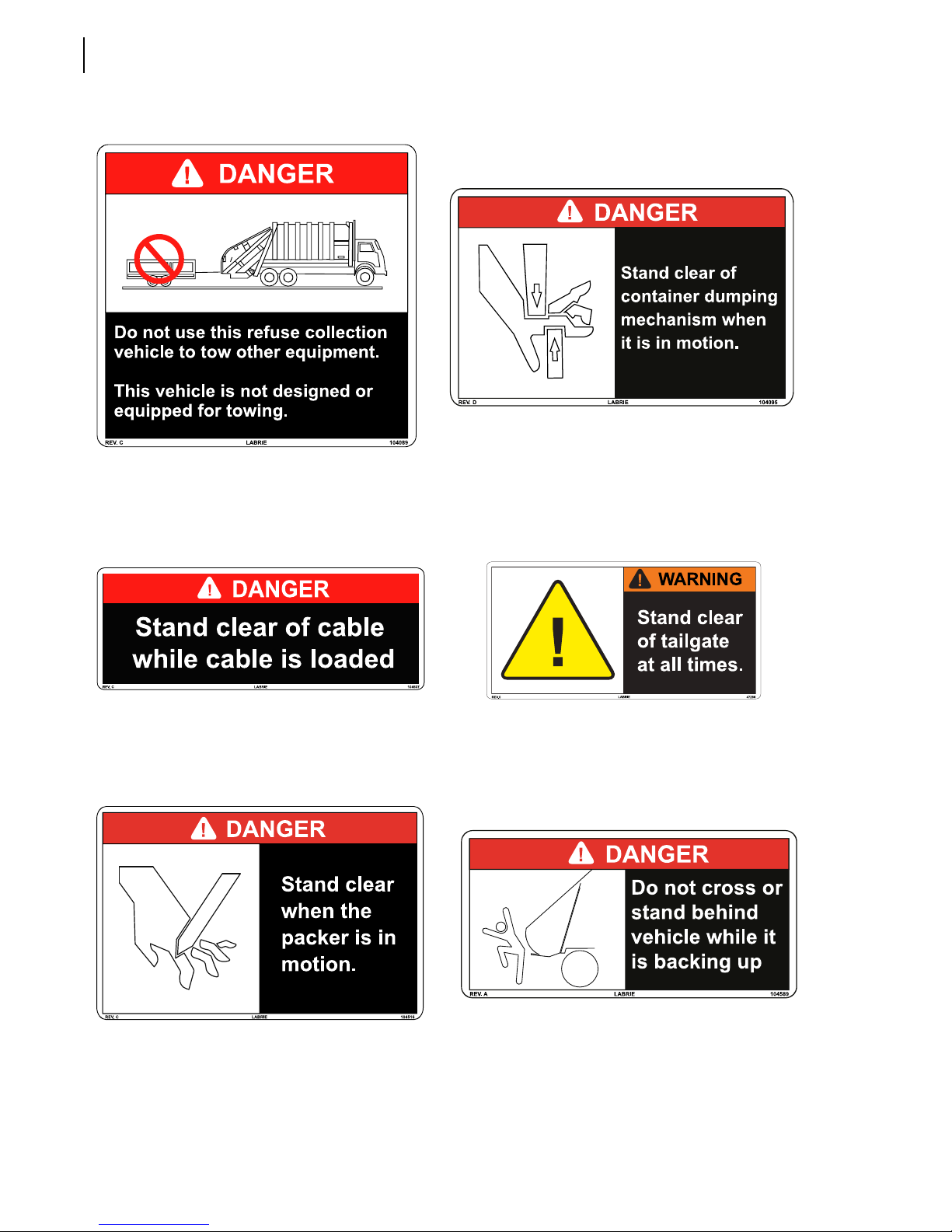
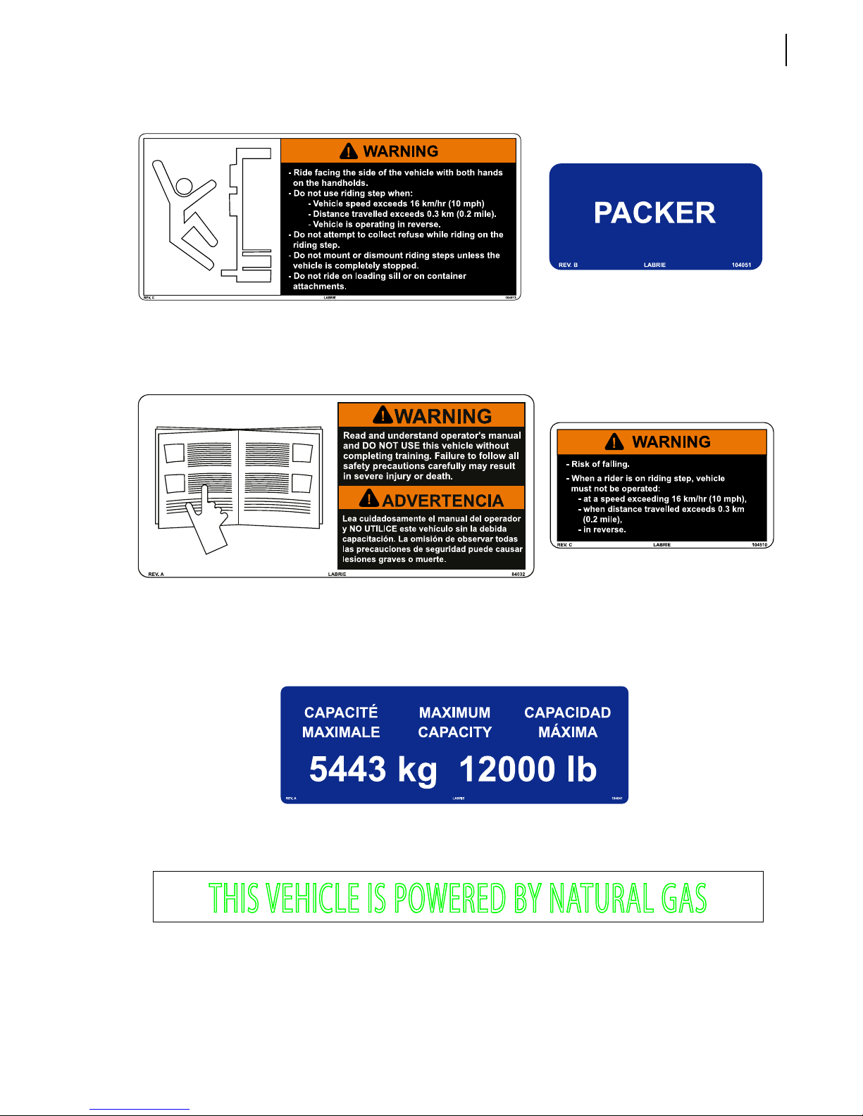
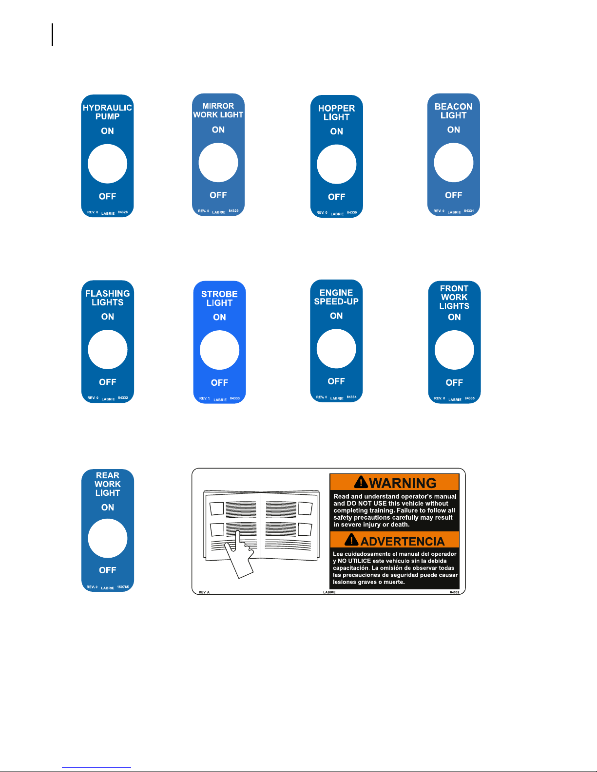
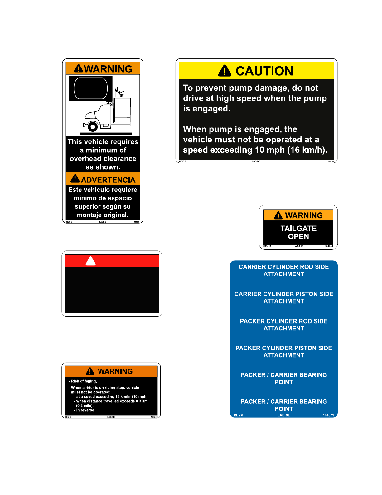
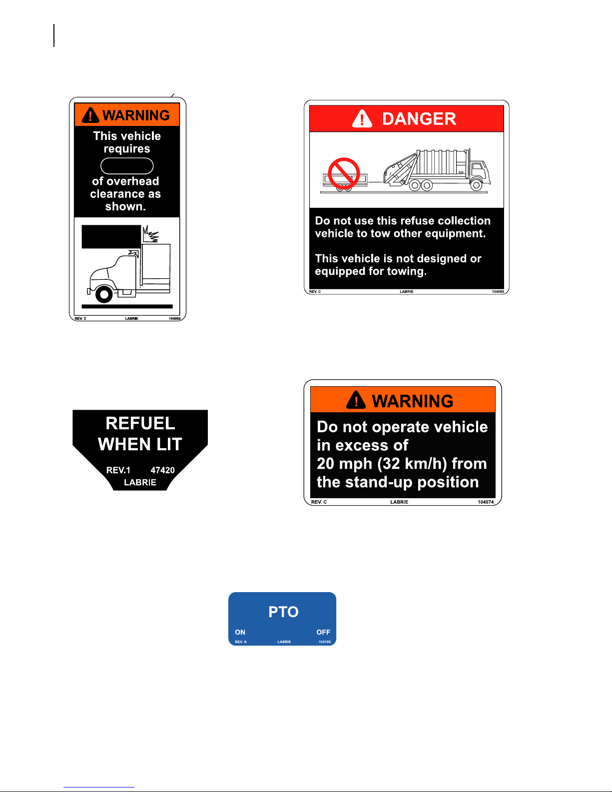
Safety and Informative Decals
Pay careful attention to all safety, warning and informative decals while working in and around the
2R-II™. Keep your decals clean and in good condition at all times. For replacement decals, please call
LabriePlus. Decals may vary from one unit to another depending on the options and features installed
on the unit. The following is an illustrated list of decals, but not limited to.
Page 25
Decals on Body
Safety Precautions 17
104059
104058 - Spanish
104060 - French
104549
104057 - Spanish
104056 - French
47304
120989 - English/Spanish
79846 - English/French
104504
84278 - English/Spanish
84277 - English/French
104035
104036 - Spanish
104034 - French
104029
104030 - Spanish
104028 - French
Page 26
18 Safety Precautions
104041
104042 - Spanish
104040 - French
104531
104532 - Spanish
104530 - French
84488
104068
84166 - English/Spanish
84165 - English/French
104092
104093 - Spanish
104091 - French
Page 27
32272
Safety Precautions 19
121349
47520
47521 - French
32411
Optional
47256
84419 - Spanish
159761 - French
Optional
159828
Optional
121344
Page 28
20 Safety Precautions
97832 84447 - Spanish
159759 - French
Optional
159805 159807 - Spanish
159806 - French
Optional
159852
58704 - French
Optional
Page 29
UNLOADING INSTRUCTIONS
FOR PUSHOUT SYSTEM
TO OPEN TAILGATE
1. Activate the hydraulic pump. (Cab controls not shown).
2. Turn solenoid to "ON" po sition (Cab controls not
shown).
3. Always set brakebefore leaving cab.
4. A. Manual latch: Loosen tai lgate latches and swing
clear (See figure A).
B. Remote latch (opt ional): Press latch unlock
button until both latches are re leased.
(See figure B)
5. Press speed up bu tton and hold (See figure C).
6. Move tailgate lev er rearward and hold until tailgat e is
fully open then releas e both lever and speed up
button.
7. Never leave unit u nattended when tailgate is open
NOTE
: Do not allow anyone to stand or cross under the
open tailgate.
TO UNLOAD BODY
1. Press speed up but ton and hold. (See figure D).
2. Move ejection l ever rearward keep it in this posit ion
until the ejector panelstops moving. (See figure E).
3. Release speed up but ton
4. Move ejection l ever forward (See figure F) and hold
until pushout plateis fully retracted for transport
(See figure G) .
5. Before reloading r epeat 1 and 2. Then move ejection
lever forward untilpushout panel is moved forward
approximately 30 inches .
TO CLOSE THE TAILGATE
1. Disengage pump.
2. Move unt forward slowly until tailgate is clear of the
expelled load. Do notmove unit more than necessary
with tailgate raised.
3. Move tailgate lev er gently forward to allow tailga te to
close. Do not allow t ailgate to slam shut.
(See figure H).
4. A. Manual latch: Swing both tailgate latches back to
latch position and tigh ten evenly and securely
(See figure I).
B. Remote latch (opt ional): Engage pump and press
tailgate lock button an d hold until both latches are
locked (See figure J) .
NOTE
: Do not travel with t ailgate manual latches
unlatched or loose or optional remote latches
unlatched
A
C
E
G
I
SPEEDUP
BUTTON
UNLOADING
B
TAILGATE
LATCH
UNLOCK
D
SPEEDUP
BUTTON
F
H
J
TAILGATE
LATCH
LOCK
SPEEDUP
BUTTON
SPEEDUP
BUTTON
Safety Precautions 21
EJECTION
TAILGATE
EJECTION
TAILGATE
WARNING
104560
104561 - Spanish
104559 - French
Ensure that all persons stay clear of the
tailgate before using the levers
104501
104502 - Spanish
104500 - French
LABRIE 104560REV. B
104519
84284 - English/Spanish
84283 - English/French
Page 30
22 Safety Precautions
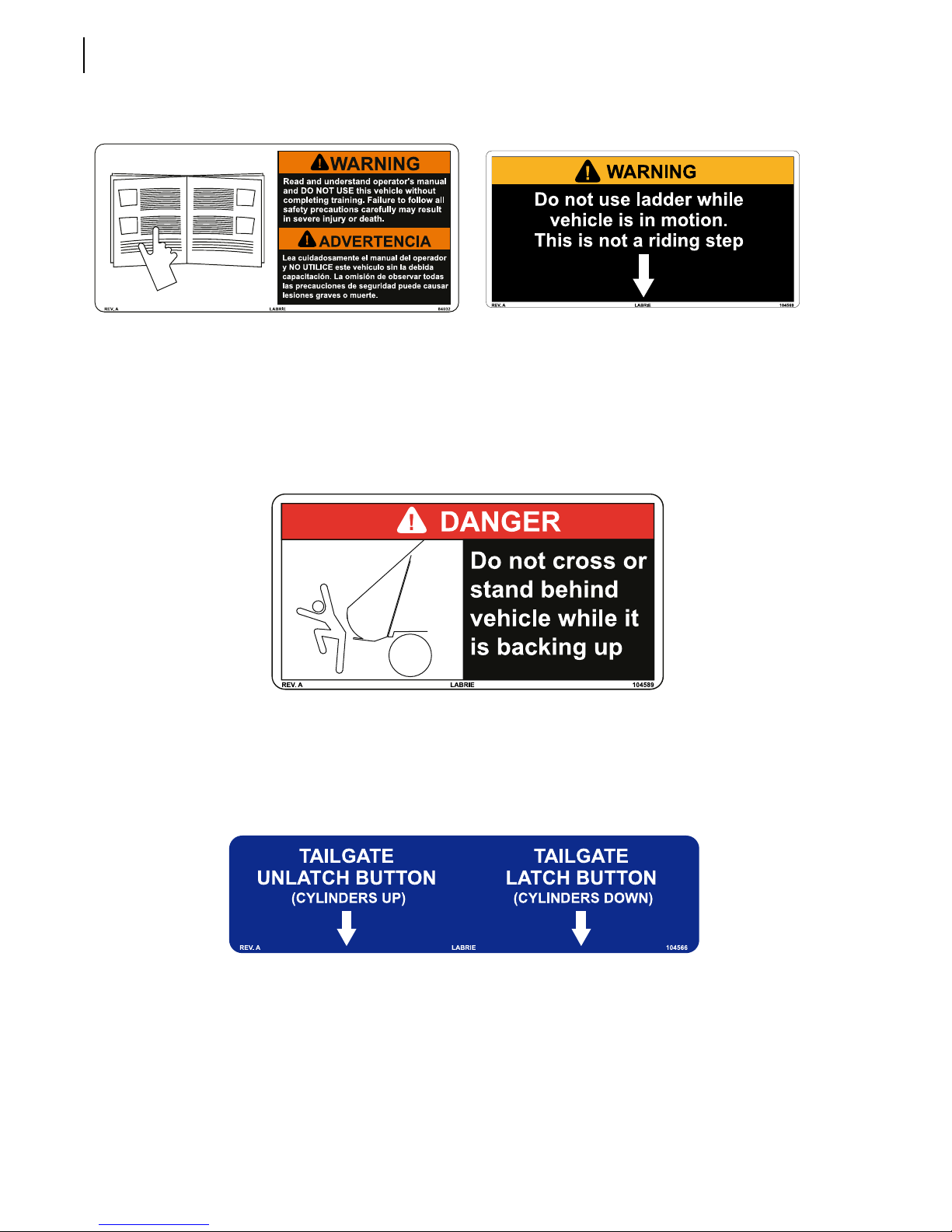
84032
84031 - English/French
104539 - English/French/Spanish
104569
84294 - English/Spanish
84293 - English/French
104589
84286 - English/Spanish
84285 - English/French
104566
104567 - Spanish
104565 - French
Optional
Page 31
Safety Precautions 23
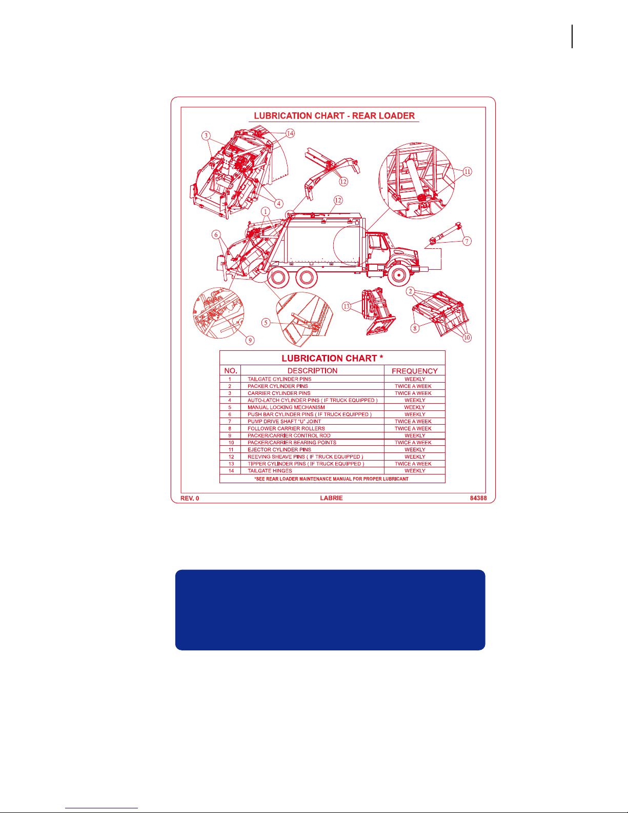
84388
84389 - French
This vehicle conforms to all ANSI Z 245.1
REV. C LABRIE 104044
104044
104045 - Spanish
104043 - French
safety requirements effective on the
manufacturing date.
Page 32
24 Safety Precautions
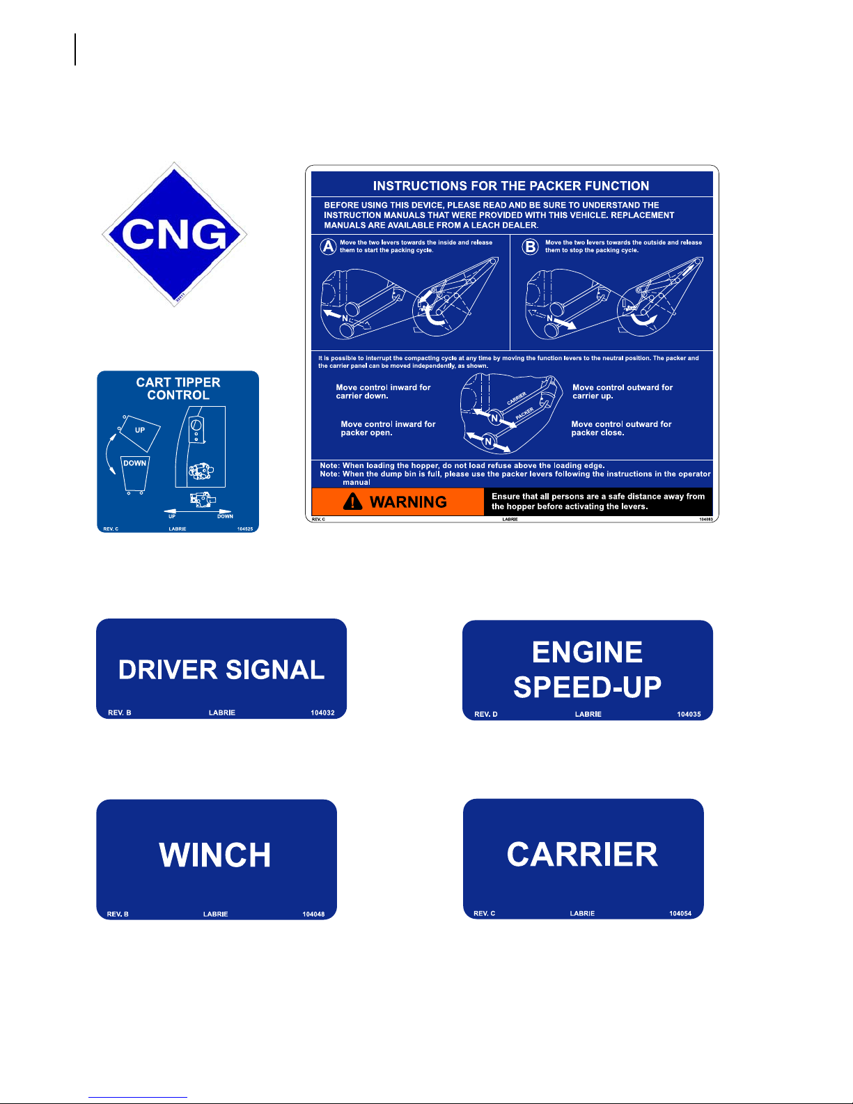
Decals on Tailgate
32411
Optional
104525
104526 - Spanish
104524 - French
104032
104033 - Spanish
104031 - French
104048
104049 - Spanish
104047 - French
104083
104084 - Spanish
104082 - French
104035
104036 - Spanish
104034 - French
104054
104055 - Spanish
104053 - French
Page 33
Safety Precautions 25
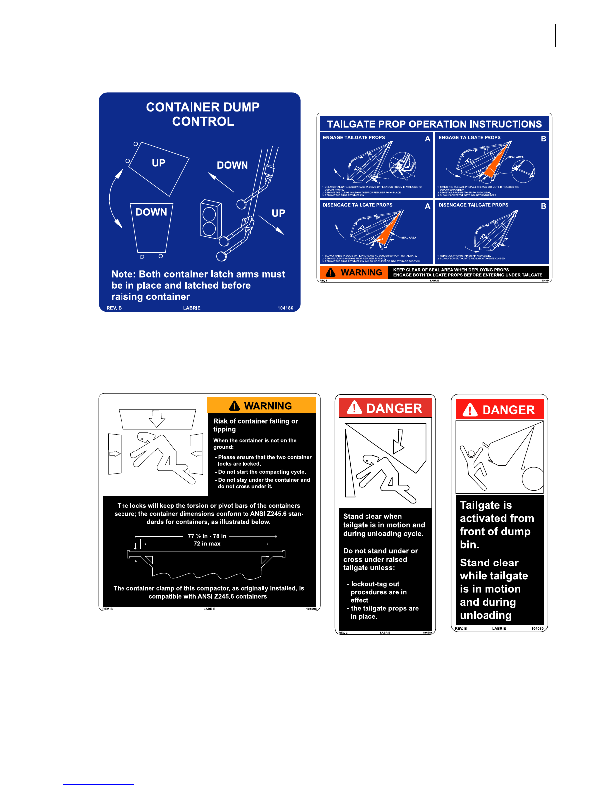
104186
104187 - Spanish
104185 - French
104534
104535 - Spanish
104533 - French
104098
104099 - Spanish
104097 - French
104519
84284 - English/Spanish
84283 - English/French
104080
104081 - Spanish
104079 - French
Page 34
26 Safety Precautions
104089
104090 - Spanish
104088 - French
104507
104508 - Spanish
104506 - French
104095
84290 - English/Spanish
84289 - English/French
47266
120973 - English/Spanish
79835 - English/French
104516
84292 - English/Spanish
84291 - English/French
104589
84286 - English/Spanish
84285 - English/French
Page 35
Safety Precautions 27
104513
84282 - English/Spanish
84281 - English/French
84032
84031 - English/French
104539 - English/French/Spanish
104051
104052 - Spanish
104050 - French
104510
84280 - English/Spanish
84279 - English/French
104641
THIS VEHICLE IS POWERED BY NATURAL GAS
32414
84418 - Spanish
159760 - French
Optional
Page 36
28 Safety Precautions
Decals inside Cab
84328
104665 - French
84332
104667 - French
84329 84330
104666 - French
84333
173541 - French
84334
104668 - French
84331
84335
104669 - French
159765
104670 - French
84032
84031 - English/French
104539 - English/French/Spanish
Page 37
104038
84164 - English/Spanish
84163 - English/French
Safety Precautions 29
84189
84188 - English/French
!
DANGER
- Do not transport containers
with the lifting devices.
- Transporting a container could
result in personal injury or
property damage.
LABRIE 104071REV. C
104071
104072 - Spanish
104070 - French
104001
104002 - Spanish
104000 - French
104510
84280 - English/Spanish
84279 - English/French
104671
104672 - French
Page 38
30 Safety Precautions
104092
104093 - Spanish
104091 - French
104089
104090 - Spanish
104088 - French
47420
84420 - Spanish
159755 - French
Optional
104074
104075 - Spanish
104073 - French
104166
104167 - Spanish
104165 - French
Page 39
Safety Features
Back Up Alarm
The back up alarm sounds when the transmission is put into reverse or when the tailgate opens.
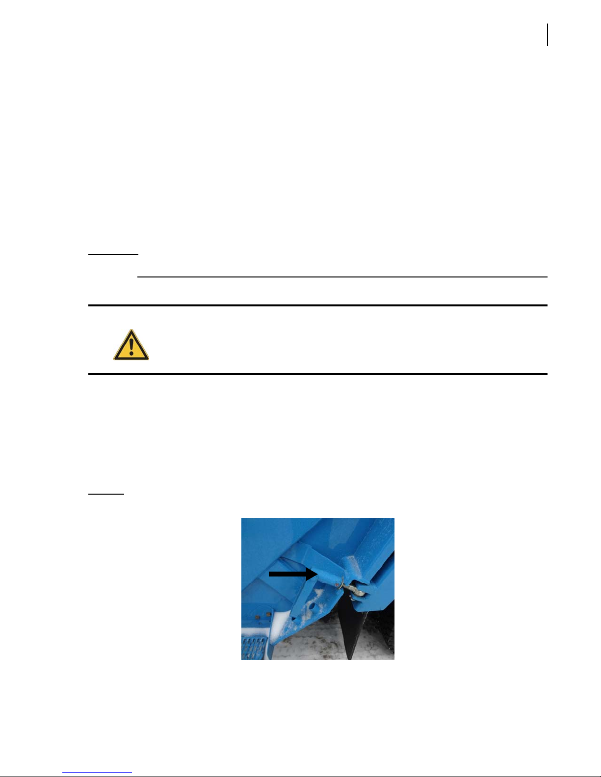
Tailgate Safety Props
The tailgate safety props are used to support and keep the tailgate open during inspection or
maintenance procedures. It is mandatory to set the safety props every time the tailgate is open for
such purposes.
The tailgate safety props are located under the tailgate, one on each side.
IMPORTANT: Make sure that the body is empty before installing the safety props.
Safety Precautions 31
Danger!
Setting the Tailgate Safety Props (for units equipped with standard tailgate clamps)
To set the tailgate safety props:
1. Make sure that the body is empty.
2. Remove the tailgate clamps. To do so:
Figure 2-2
The tailgate safety props shall be set each time the tailgate is open for inspection or
maintenance purposes.
2 a. Loosen the clamp.
2 b. Swing the clamp away from the body.
Tailgate clamp
3. Start the engine.
Page 40
32 Safety Precautions
4. Turn the pump ON.
Danger!
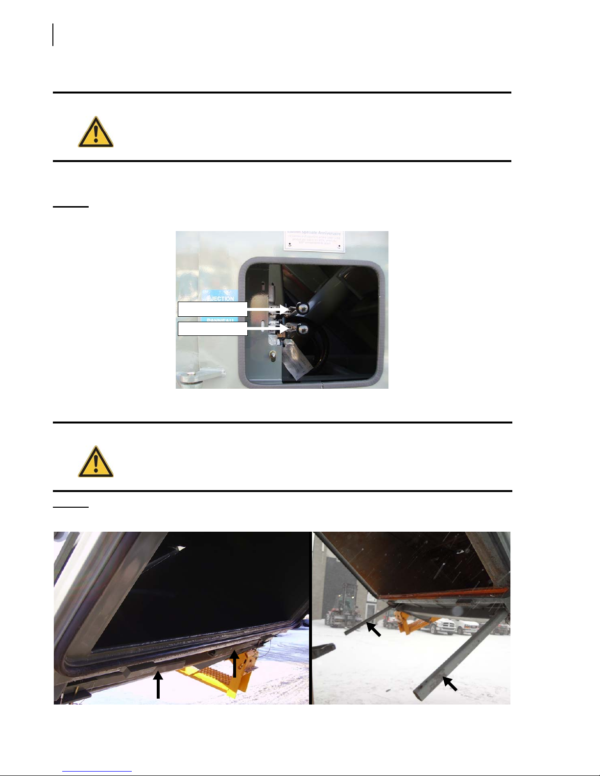
5. Using the TAILGATE lever raise the tailgate about 3 feet (enough to swivel both safety props
Figure 2-3
Prior to raising the tailgate, make sure that no one is standing behind the vehicle and that
the body is empty.
towards the body).
T
AILGATE/PUSHOUT
levers
Pushout Lever
Tailgate Lever
6. Unlatch each prop from its stored position and swivel it towards the body (see Figure 2-4).
Danger!
Figure 2-4
Stand clear of tailgate path while setting the safety props.
Props in stored position (left) and in service position (right)
Page 41
Safety Precautions 33
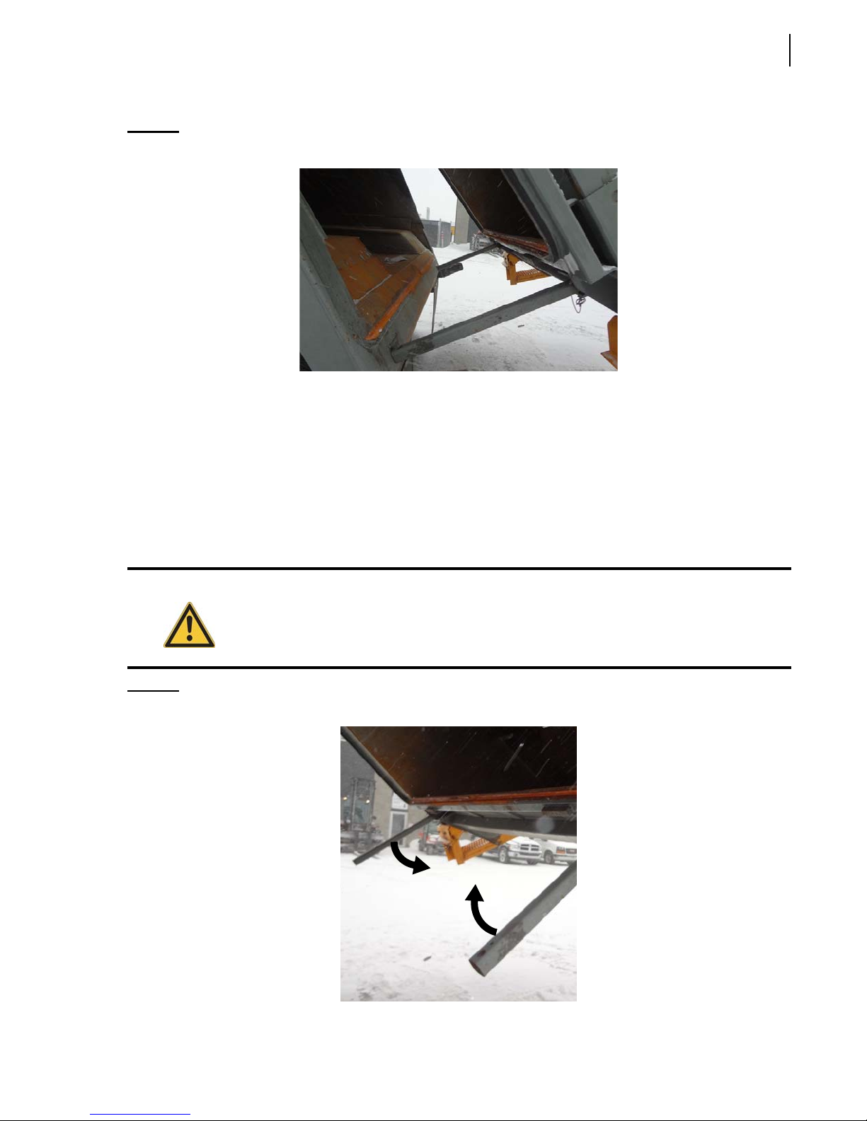
7. Lower the tailgate until both safety props lean against the body base using the TAILGATE lever.
Figure 2-5
Putting the Tailgate Safety Props Back in Place (for units with tailgate clamps)
To put the tailgate safety props back into their stored position:
1. Start the engine.
2. Turn the pump ON.
3. Raise the tailgate by about 3 feet using the TAILGATE lever (see Figure 2-3).
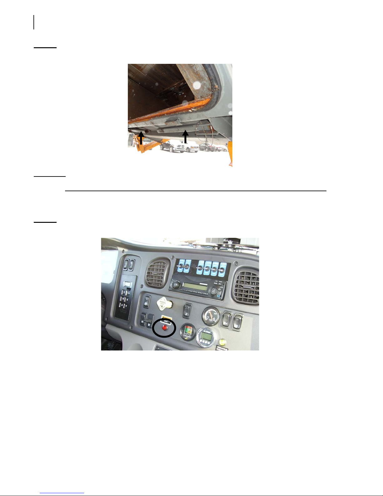
4. Swivel back each safety prop and latch it into place under the tailgate (see Figure 2-6 and Figure
Props leaned against body base
2-7).
Danger!
Figure 2-6
Stand clear of tailgate path while putting the safety props back into their stored position.
Putting back props into stored position
Page 42
34 Safety Precautions
Figure 2-7
IMPORTANT: Secure each prop using the provided latch.
Props in stored position
5. Using the TAILGATE lever (see Figure 2-3), completely close the tailgate.
TAILGATE OPEN light indicator should turn off.
The
Figure 2-8
T
AILGATE OPEN
light indicator
6. Put the tailgate clamps back in place (see Figure 2-2). To do so:
6 a. Swivel back the clamp against the body.
6 b. Tighten the clamp properly.
Setting the Tailgate Safety Props (for units equipped with the optional hydraulic tailgate locking
mechanism)
To set the tailgate safety props:
1. Make sure that the body is empty.
Page 43
2. Start the engine.
3. Turn the pump ON.
Safety Precautions 35
Danger!
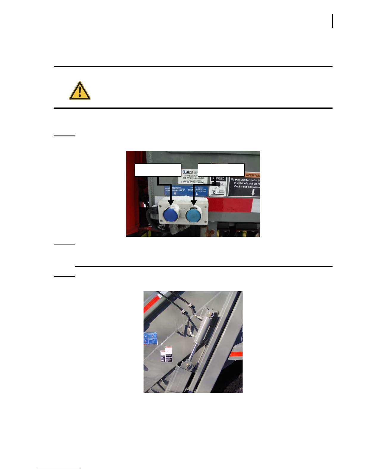
4. Using the tailgate unlatch button on the body left-side corner near the access door, unlock the
Figure 2-9
Prior to raising the tailgate, make sure that no one is standing behind the vehicle and that
the body is empty.
tailgate.
Tailgate locking/unlocking controls
To unlock tailgate To lock tailgate
NOTE: When the tailgate is unlocked, both locking mechanism cylinders are retracted. They are
extended when the tailgate is locked.
Figure 2-10
Locking mechanism cylinder
5. Using the TAILGATE lever raise the tailgate about 3 feet (enough to swivel both safety props
towards the body) [see Figure 2-3].
Page 44

36 Safety Precautions
6. Unlatch each prop from its stored position and swivel it towards the body (see Figure 2-4).
Danger!
7. Lower the tailgate until both safety props lean against the body base using the TAILGATE lever
Stand clear of tailgate path while setting the safety props.
(see Figure 2-5).
Putting the Tailgate Safety Props Back in Place (for units equipped with the optional hydraulic
tailgate locking mechanism)
To put the tailgate safety props back into their stored position:
1. Start the engine.
2. Turn the pump ON.
3. Raise the tailgate by about 3 feet using the TAILGATE lever (see Figure 2-3).
4. Swivel back each safety prop and latch it into place under the tailgate (see Figure 2-6 and Figure
2-7).
Danger!
Stand clear of tailgate path while putting the safety props back into their stored position.
IMPORTANT: Secure each prop using the provided latch.
5. Using the TAILGATE lever (see Figure 2-3), completely close the tailgate.
TAILGATE OPEN light indicator should turn off (see Figure 2-8).
The
6. Using the tailgate latch button on the body left-side corner near the access door (see Figure 2-9),
lock the tailgate.
NOTE: When the tailgate is unlocked, both locking mechanism cylinders are retracted. They are
extended when the tailgate is locked.
Camera System
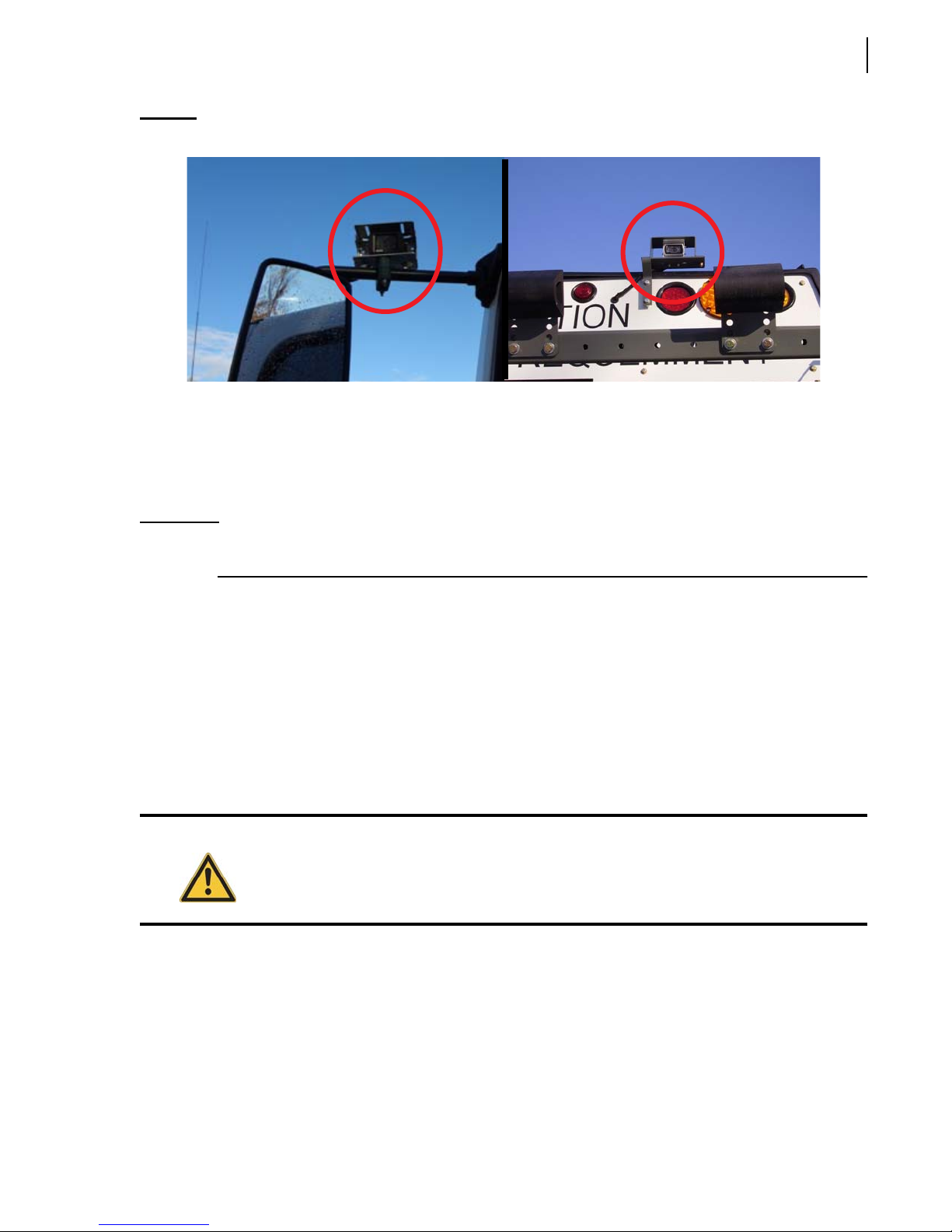
2R-II™ units can be equipped with up to two (2) cameras. These cameras can be installed:
on the upper part of the tailgate (standard feature) [see Figure 2-11, right], and
on the left-hand side mirror (optional feature) [see Figure 2-11, left].
The operator can switch from one camera to the other using a selector switch located on the in-cab 7”
LCD color monitor.
Refer to the camera manufacturer’s manual for more information.
Page 45
Safety Precautions 37
Figure 2-11
Camera on the left-hand side mirror (left), and on the tailgate (right)
Tailgate Open Proximity Switch Test
The Tailgate Open Proximity Switch Test should be part of your daily inspection. Successful
completion of this test ensures that your unit is safe to operate. If this test fails, do not operate your
unit until the appropriate adjustment or service has been completed.
IMPORTANT: Your rear loader unit may require other safety tests not mentioned herein. Consult your supervisor
and/or maintenance department if you have questions or you are in doubt.
A. For this test, proceed as follows (on units equipped with standard tailgate clamps):
1. Make sure that the body is empty.
2. Remove both tailgate clamps (see Figure 2-2). To do so:
2 a. Loosen the clamp.
2 b. Swing the clamp away from the body.
3. Start the truck.
4. Engage the pump.
5. Using the TAILGATE lever (see Figure 2-3), raise the tailgate by a few feet.
Danger!
Prior to raising the tailgate, make sure that no one is standing behind the vehicle and that
the body is empty.
When the tailgate is raised, the in-cab buzzer and the backup alarm should sound and the
T
AILGATE OPEN indicator light on the dashboard (or on the console) should turn on. Check they
are all working. If for some reason any of these elements are not activated, report this to your
supervisor or maintenance personnel.
6. Using the TAILGATE lever, lower and close the tailgate.
The in-cab buzzer and the backup alarm should stop sounding, and the T
indicator light should go off.
AILGATE OPEN
Page 46
38 Safety Precautions
7. Put both tailgate clamps back to their lock position.
B. For this test, proceed as follows (on units equipped with the optional hydraulic tailgatelocking mechanism):
1. Make sure that the body is empty.
2. Start the truck.
3. Engage the pump.
4. Using the tailgate unlatch button on the body left-side corner near the access door (see Figure
2-9), unlock the tailgate.
5. Using the TAILGATE lever (see Figure 2-3), raise the tailgate by a few feet.
Danger!
Prior to raising the tailgate, make sure that no one is standing behind the vehicle and that
the body is empty.
When the tailgate is raised, the in-cab buzzer and the backup alarm should sound and the
T
AILGATE OPEN indicator light on the dashboard (or on the console) should turn on. Check they
are all working. If for some reason any of these elements are not activated, report this to your
supervisor or maintenance personnel.
6. Using the TAILGATE lever, lower and close the tailgate.
The in-cab buzzer and the backup alarm should stop sounding, and the T
AILGATE OPEN
indicator light should go off.
7. Using the tailgate latch button on the body left-side corner near the access door (see Figure 2-9),
lock the tailgate.
Locking Out and Tagging Out the Vehicle
For any inspection, repair or general maintenance being done on the vehicle, whether on the road or
at the shop, it is the employer’s responsibility to establish and see to the application of a proper
lockout and tagout procedure.
To lock out and tag out a 2R-II™ unit:
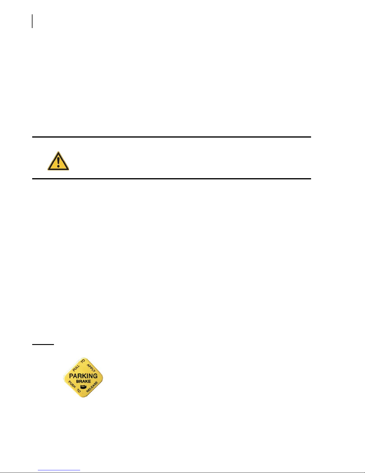
1. Park the vehicle on safe level ground, and apply the parking brake (see Figure 2-12).
Figure 2-12
Parking brake sign
2. Make sure that the body is completely unloaded.
3. Switch off the hydraulic pump.
Page 47
Safety Precautions 39
4. Turn off the engine, remove the key from the ignition, store it in a safe and controlled area
(preferably on yourself), and tape over the ignition switch.
5. Turn off and lock the master switch.
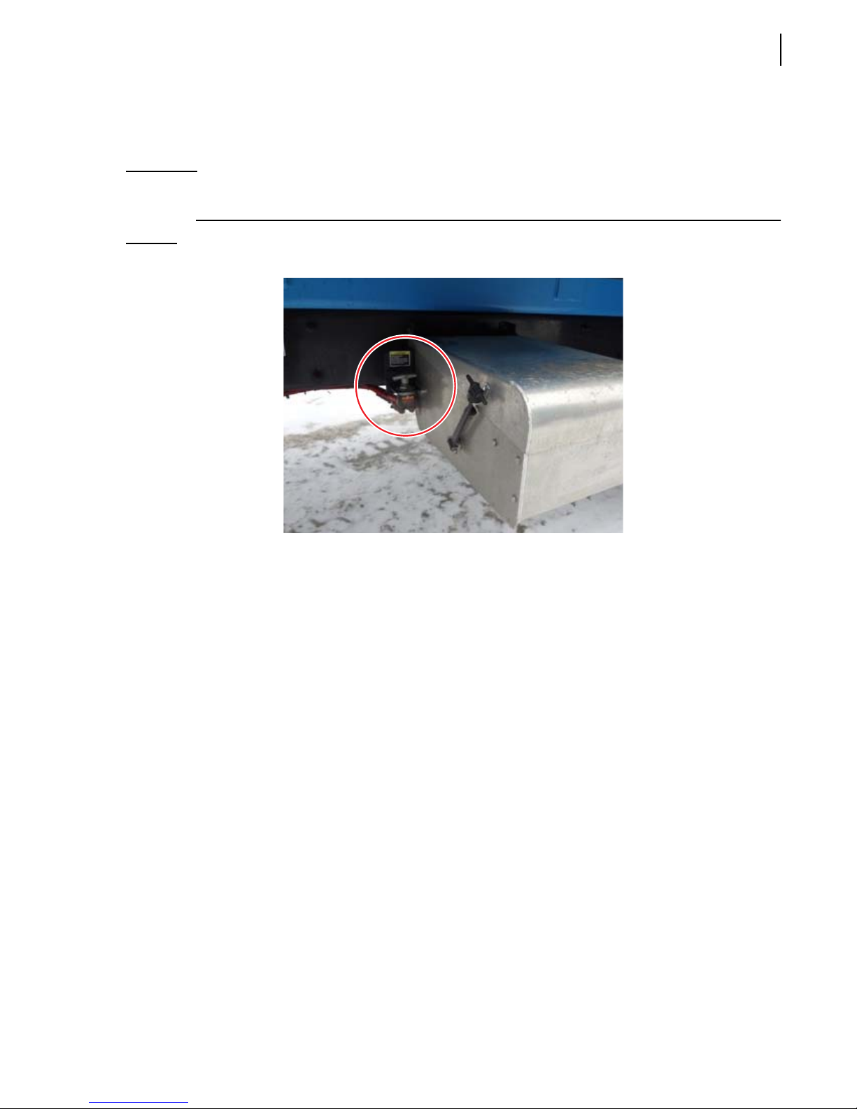
IMPORTANT: The battery set of the 2R-II™ is equipped with a master switch (see Figure 2-13) that must be turned
off.
Figure 2-13
6. Chock all wheels.
7. Put an “OFF SERVICE” tag on the driver’s wheel and on the front windshield.
8. Use safety props to block an open tailgate to prevent movement due to gravity.
9. Drain all air tanks.
10. Verify and inspect any security device and/or mechanism to make sure that there is no bypass
Master switch
and that they are all functional.
Page 48
40 Safety Precautions
Shutting Down the Vehicle
If the vehicle has to be stored for an extended period of time, follow the chassis manufacturer’s
shutdown and maintenance requirements.
Also:
1. Park the vehicle on a hard level surface, and apply the parking brake (see Figure 2-12).
2. Make sure that all moving parts are in their “home” position (tailgate, packer, etc.).
3. Turn off, in sequence, the hydraulic pump (see Figure 2-16), the electrical system, the engine and
the master switch (see Figure 2-13).
4. Drain all air tanks.
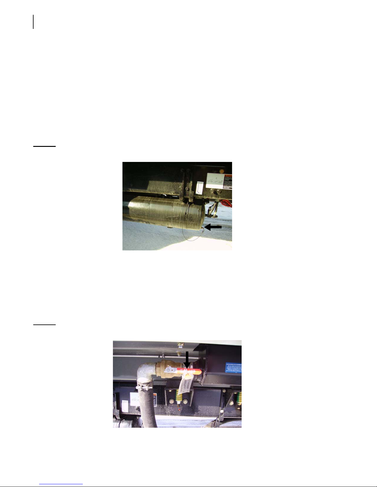
Figure 2-14
Drain valve on air tank
Prior to Start Up
Before starting the vehicle:
1. Make sure no system will engage and/or start to operate as you start the engine.
2. Make sure the shut-off valve on the hydraulic tank is fully open before starting the vehicle
(see Figure 2-15).
Figure 2-15
Suction line shut-off valve
Page 49
Safety Precautions 41
NOTE: The hydraulic tank model may vary according to the options installed on the vehicle.
Warning!
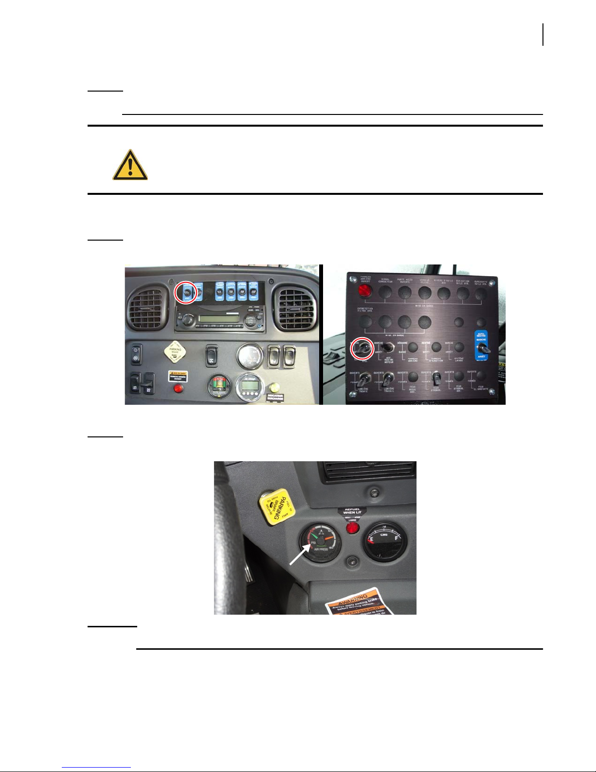
3. Engage the hydraulic system by switching on the Pump ON/OFF switch on the cab dashboard or
Figure 2-16
Failure to fully open the main valve will cause immediate damage to the pump, even if
the pump is turned off.
on the console (see Figure 2-16).
Hydraulic pump ON/OFF switch on the dashboard (left), on the console (right)
Once the engine is started, wait for air pressure to build up to at least 70 psi.
Figure 2-17
IMPORTANT: Do not operate or move the vehicle until air pressure has reached 70 psi.
Air pressure indicator
Page 50

42 Safety Precautions
Page 51
3
Controls,
Indicators and
Processes
The 2R-II™ has a series of controls and indicators that
allow easier operation of the different functions that
come with the vehicle. The indicators are mainly
located on the in-cab console or on the dashboard,
while the operating controls are mostly located on the
right side of the tailgate and some on the front body
left side near the access door.
It is imperative that the operator familiarize himself
with the layout and function of all the controls
required to operate the 2R-II™.
Also, at the end of this section, you will find basic
information on the container/waste handling
processes as well as terms that are commonly used in
this field.
In-Cab Controls
While most of the controls of the 2R-II™ are located on
the tailgate and on the body, a few are found inside the
cab.
The following are the in-cab controls:
Parking Brake
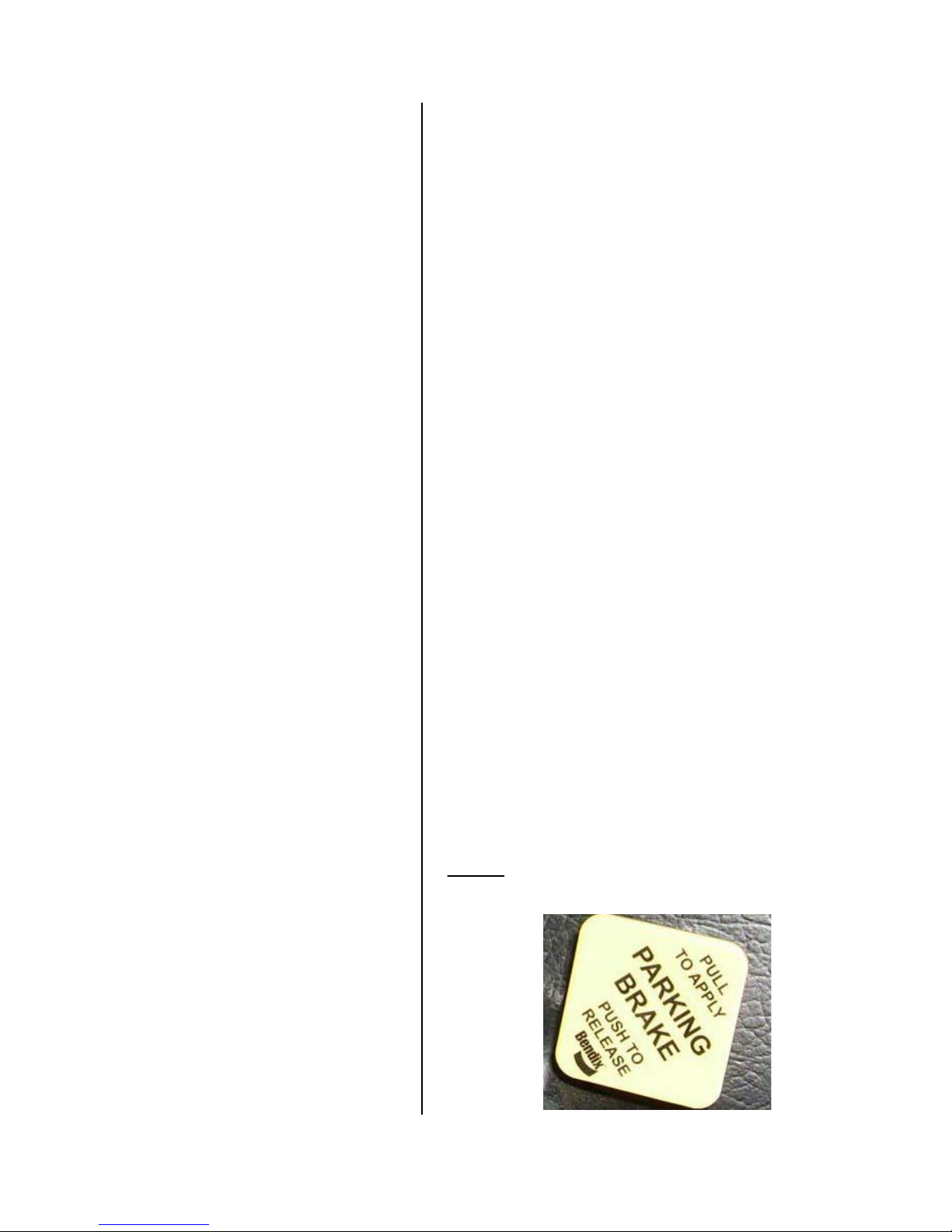
The parking brake, located on the dashboard, must be
used every time the 2R-II™ is stopped on idle position
except at regular traffic stops.
Figure 3-1
Parking brake
Page 52
44 Controls, Indicators and Processes
Pump Switch
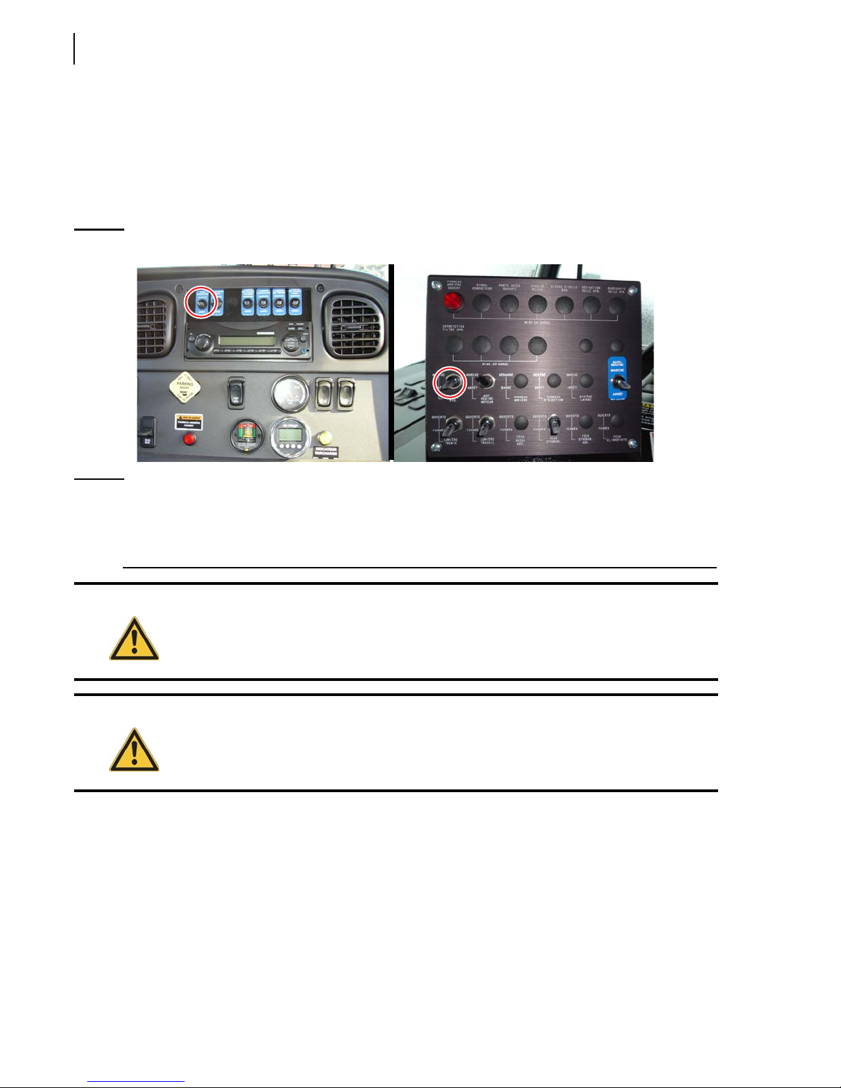
This switch, which is also called PTO switch, engages and disengages the hydraulic pump that powers
all body and tailgate functions.
Turn on this switch to activate the hydraulic pump.
Turn off this switch to deactivate the hydraulic pump.
Figure 3-2
NOTE: Even if the PTO switch is turned off, the pump may still be turning whatever the engine’s RPM.
Pump switch
This is particularly the case when the pump is mounted at the front end of the truck. It is very
important not to let the pump run dry or without oil. Otherwise, the pump will be seriously
damaged or even destroyed.
Warning!
Do not close the main valve on the hydraulic tank even if the PTO switch is turned off. The
pump may still be turning whatever the engine’s RPM, especially when the pump is mounted
at the front end of the truck. Failure to do so may seriously damage or even destroy the
pump.
Caution!
Prior to attempting any operation of the unit, make sure you are familiar with all of the safety
information contained in Section 2: Safety Precautions.
Also, be sure to read all safety decals associated with the Pump/PTO before attempting
operation.
ENGINE SPEED-UP Switch
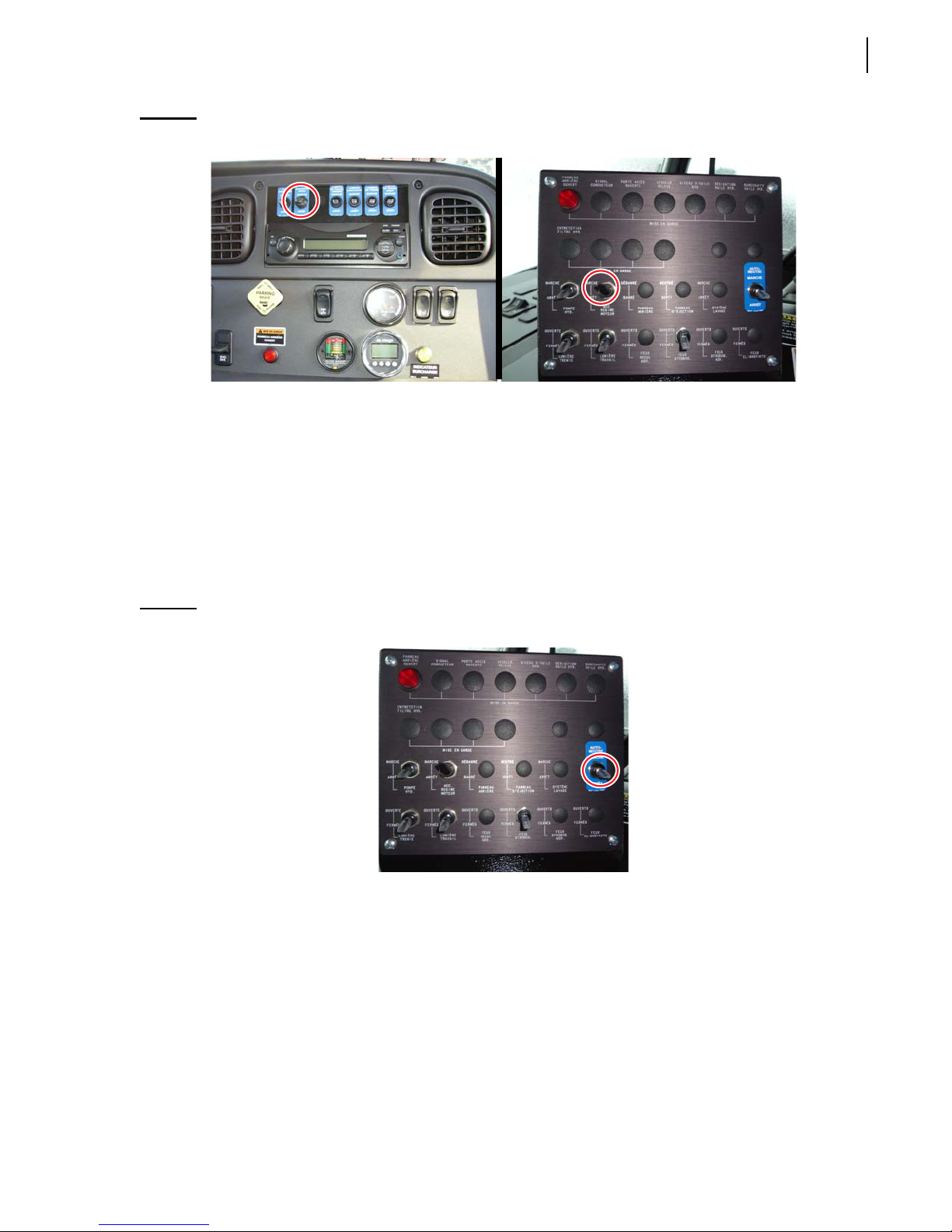
This switch energizes the engine speed-up system. It is located either on the in-cab console or on the
dashboard (see Figure 3-3).
The speed-up feature is used to rev up the pump providing additional flow to the hydraulic features
and reducing cycle times.
Toggle this switch up to activate the engine speed-up system.
Toggle this switch down to deactivate the engine speed-up system.
Page 53
Controls, Indicators and Processes 45
Figure 3-3
S
PEED-UP
switch
AUTO-NEUTRAL Switch (optional)
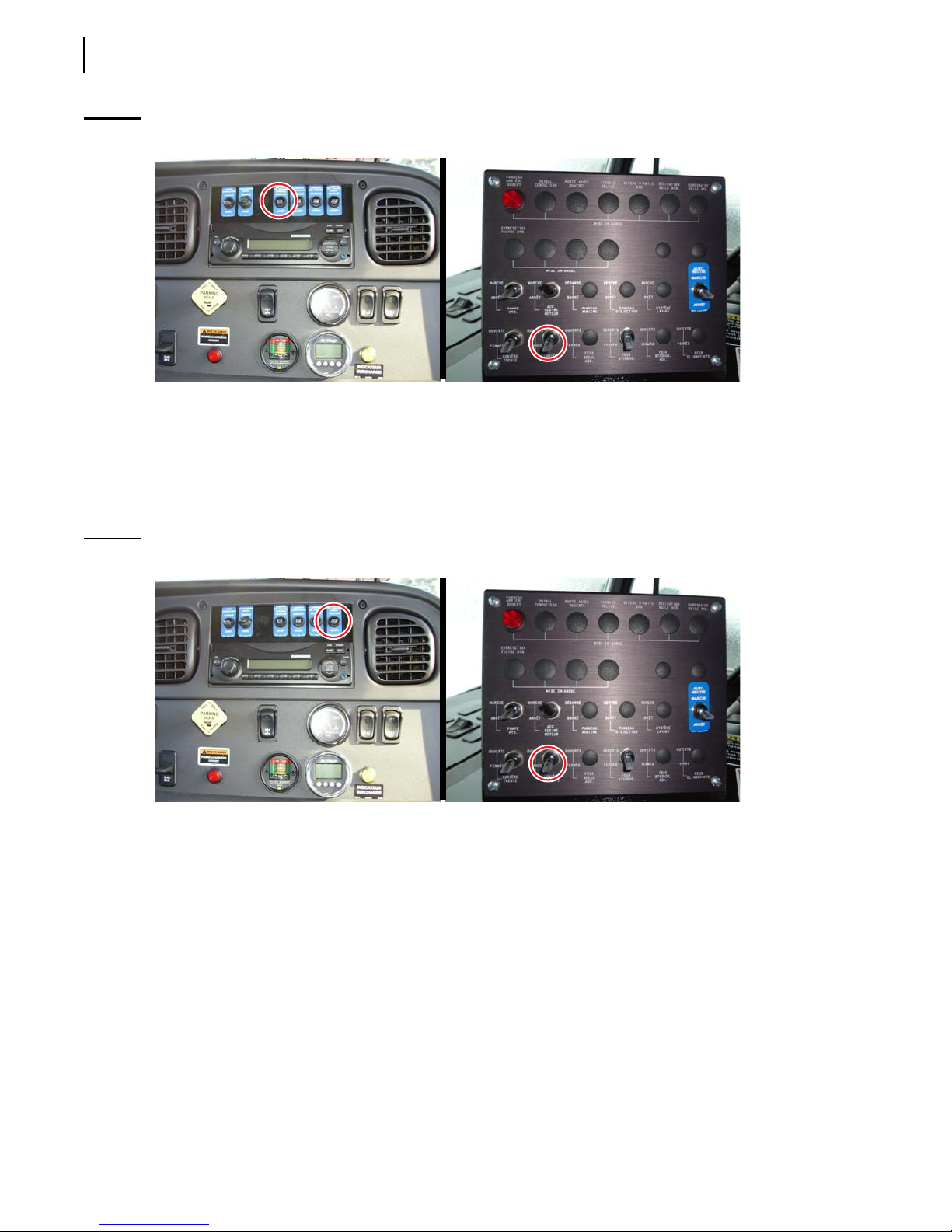
The auto-neutral system is available on units equipped with an Allison electronic transmission. The
auto-neutral allows the driver to shift from “drive” to “neutral” automatically without touching the
shifter lever. For more information on this, refer to the chassis manufacturer’s manual.
To activate the auto-neutral function, toggle the A
To deactivate the auto-neutral function, toggle the A
The optional A
UTO-NEUTRAL switch is located on the in-cab console (see Figure 3-4).
UTO-NEUTRAL control switch up.
UTO-NEUTRAL control switch down.
Figure 3-4
A
UTO-NEUTRAL
switch
REAR WORK LIGHT Switch (optional)
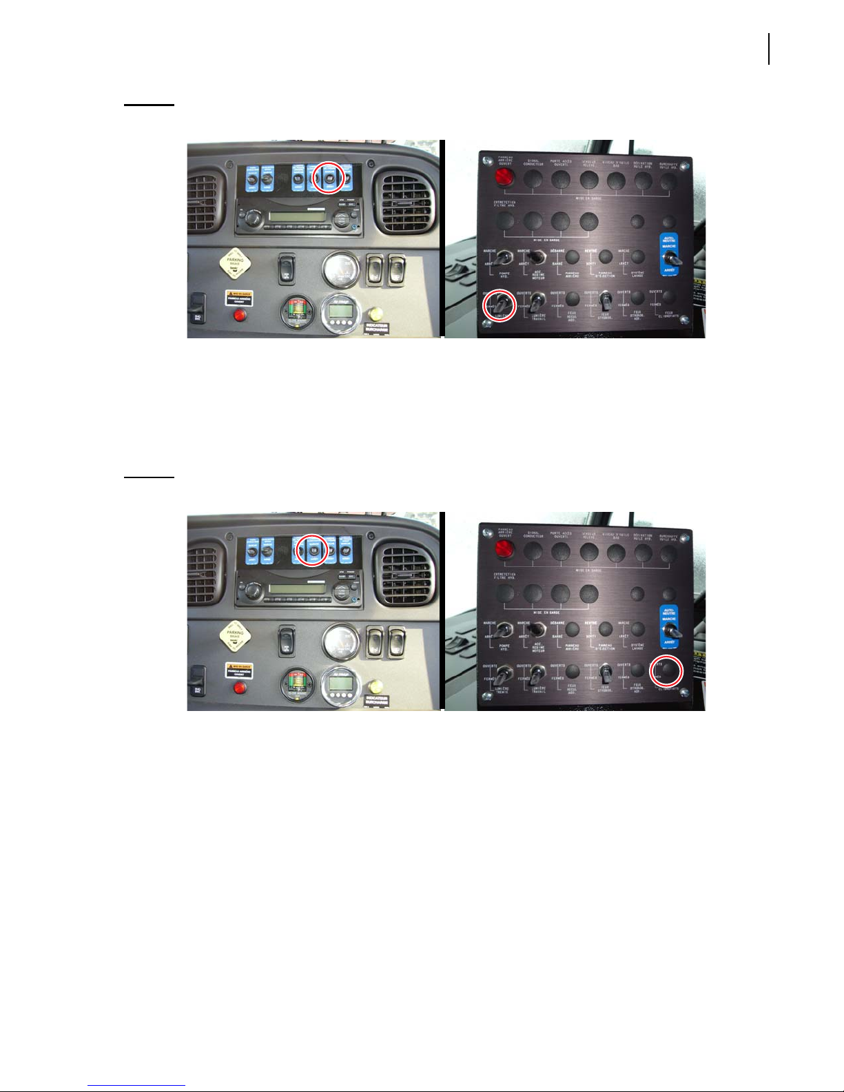
This switch (see Figure 3-5) turns on/off the rear work light if installed on your 2R-II™.
Pressing the toggle upward will turn the rear work light on.
Pressing the toggle down will turn the rear work light off.
Page 54
46 Controls, Indicators and Processes
Figure 3-5
R
EAR WORK LIGHT
switch
FRONT WORK LIGHT Switch (optional)
This switch (see Figure 3-6) turns on/off the front work light if installed on your 2R-II™.
Toggle the switch up to turn on the front work light.
Toggle the switch down to turn off the front work light.
Figure 3-6
F
RONT WORK LIGHT
switch
HOPPER LIGHT Switch (optional)
This switch (see Figure 3-7) turns on/off the hopper light if installed on your 2R-II™.
Toggle the switch up to turn on the hopper light.
Toggle the switch down to turn off the hopper light.
Page 55
Controls, Indicators and Processes 47
Figure 3-7
H
OPPER LIGHT
switch
FLASHING LIGHT Switch (optional)
This switch (see Figure 3-8) activates and deactivates the flashing lights.
Toggle the switch up to turn on the flashing lights.
Toggle the switch down to turn off the flashing lights.
Figure 3-8
F
LASHING LIGHT
switch
STROBE LIGHT Switch (optional)
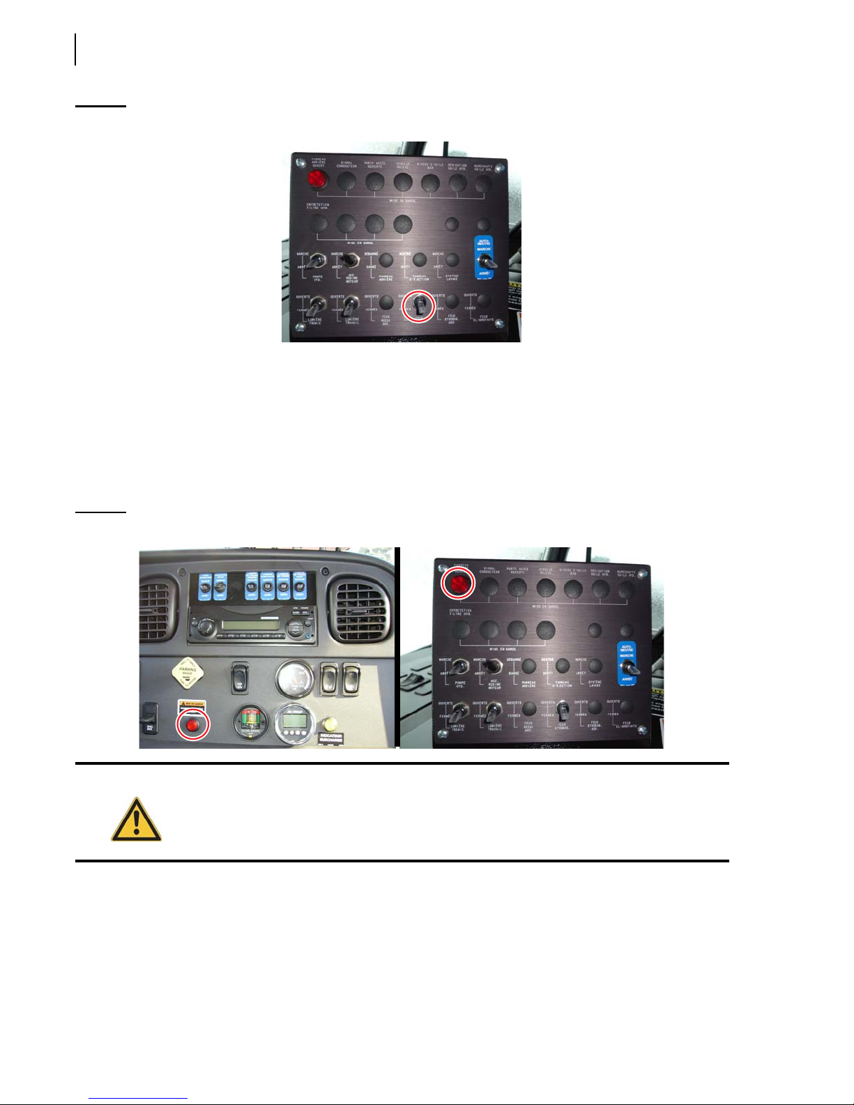
This switch (see Figure 3-9) activates and deactivates the strobe light mounted on the tailgate.
Toggle the switch up to turn on the strobe light.
Toggle the switch down to turn off the strobe light.
Page 56
48 Controls, Indicators and Processes
Figure 3-9
S
TROBE LIGHT
switch
Indicators
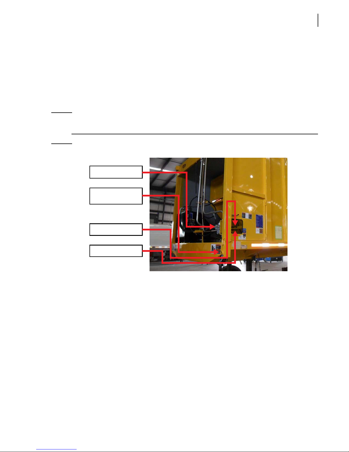
TAILGATE OPEN Light
This warning light, located either on the dashboard or on the console, will illuminate if the tailgate is
ajar. Having the tailgate ajar will also sound the backup alarm and illuminate the backup lights.
Figure 3-10
T
AILGATE OPEN
Warning!
light
Operation of the unit with an illuminated or defective warning system can result in personal
injury and/or equipment damage.
Page 57
Controls, Indicators and Processes 49
Outside Controls
Engine Speed-Up Push Button
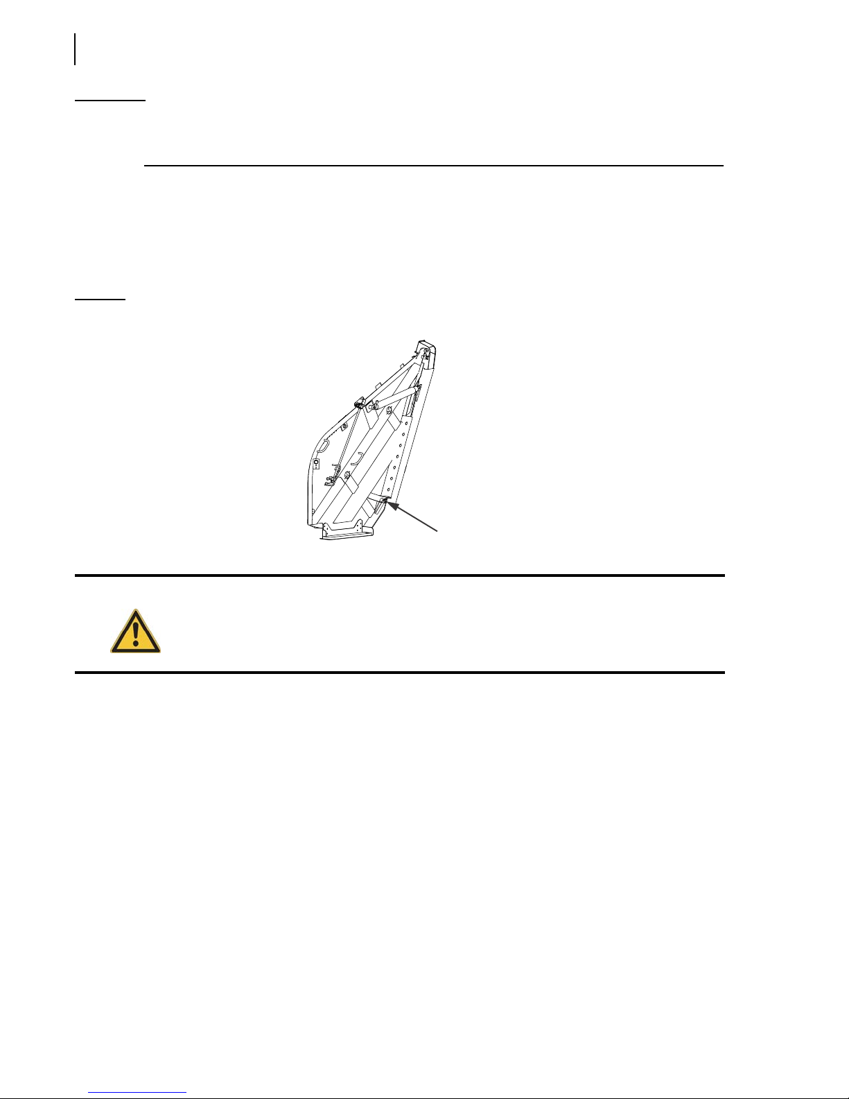
When depressed, this push button switch (see Figure 3-11) will cause the engine to speed-up and
provide additional flow to the hydraulic system. Located on the lower front left side of the body, this
button is depressed by the operator when operating either the ejection (pushout) lever or the tailgate
lever.
NOTE: Additional speed-up control buttons may be installed on the 2R-II™ with optional winches and
container handling attachments.
Figure 3-11
Controls on the body left side
Front control valve
Engine speed-up
button
Pushout lever
Tailgate lift lever
Front Control Valve
The front control valve is located behind the access door on the front left side of the body (see Figure
3-11). The control levers for this valve extend out through a cutout in the door. This valve allows the
ejection (pushout) panel to move and the tailgate to rise.
Ejection (Pushout) Lever
The upper lever (see Figure 3-11) controls the movement of the pushout panel. Moving the control
lever rearward (toward the tailgate) will move the pushout panel to the rear. Moving the control lever
forward (toward the cab) will move the pushout panel to the front.
Tailgate Lever
The lower lever (see Figure 3-11) controls the tailgate. Moving the lever rearward (toward the
tailgate) will raise the tailgate. Moving the lever forward (toward the cab) will lower the tailgate.
Page 58
50 Controls, Indicators and Processes
IMPORTANT: The tailgate must be unlocked before attempting to raise it. To know how to unlock the tailgate, see
Step 2 on Page 31 (if tailgate clamps are installed) or Steps 2, 3 and 4 on Page 35 (if the optional
hydraulic locking mechanism is installed).
Tailgate Clamps
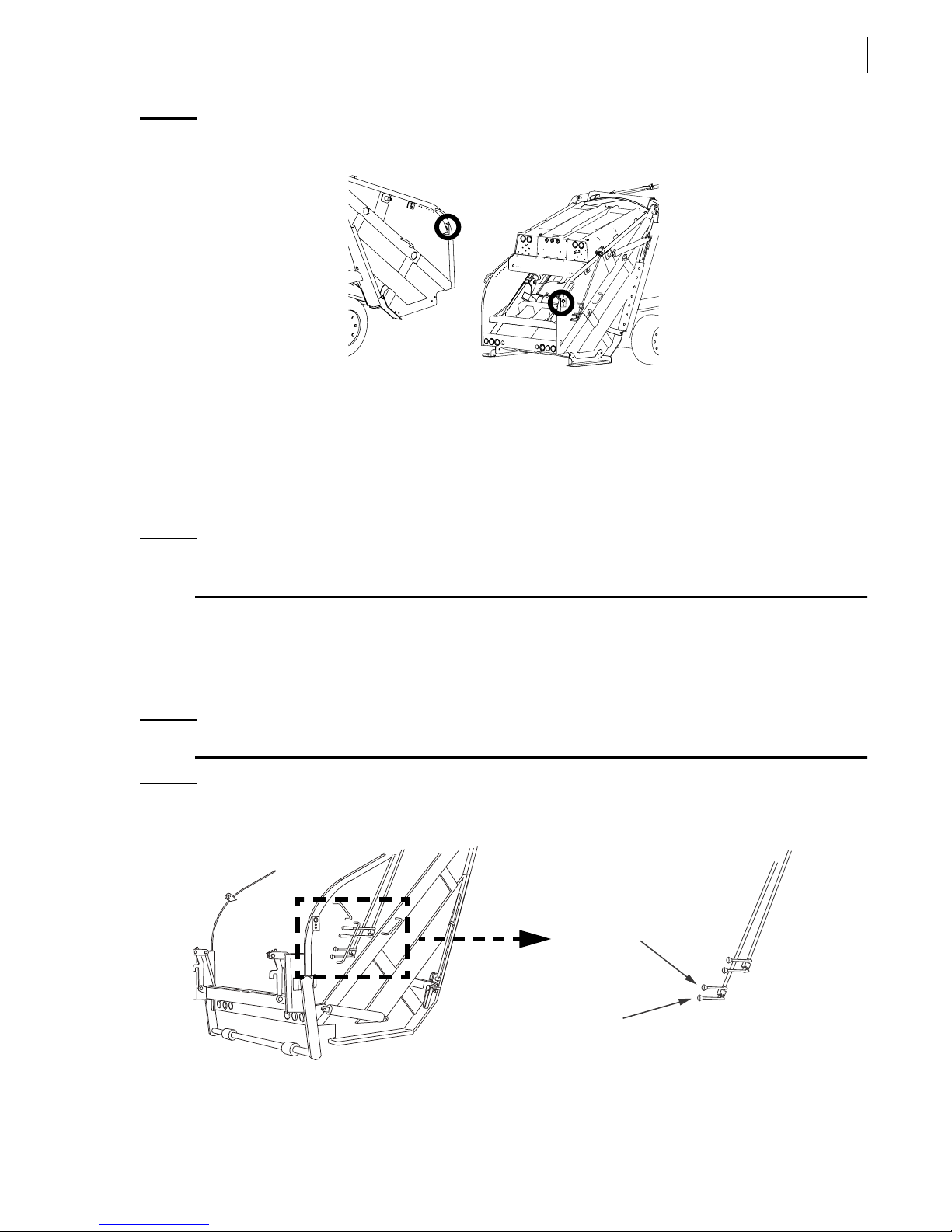
Tailgate clamps are located on each side of the tailgate at the bottom where the tailgate rests against
the body (see Figure 3-12). They are used to secure the tailgate to the body during operation. These
clamps must be manually loosened and swung away from the body before raising the tailgate.
Figure 3-12
Caution!
Tailgate clamps
TAILGATE
CLAMPS
Before attempting to loosen the tailgate clamps, pressure against the tailgate must be
relieved by opening the packer panel to the “interrupted cycle” stop position.
Hydraulic Tailgate-Locking Mechanism Buttons (optional)
These optional buttons, located on the forward left side of the body (see Figure 2-9), are used to
lock/unlock the tailgate.
Press and hold the Unlatch button to unlock the tailgate. Both locking cylinders will retract.
Press and hold the Latch button to lock the tailgate. Both locking cylinders will extend.
Driver Signal Push Buttons
The standard push button is located on the curbside of the tailgate. An optional push button may also
be located on the streetside of the tailgate. These buttons (see Figure 3-13) are connected to a buzzer
mounted under the driver’s seat or under the dash in the chassis cab. The operator depresses one of
these push buttons to signal the driver when the loading operation is completed and the truck is ready
to go.
Page 59
Controls, Indicators and Processes 51
Figure 3-13
Driver signal buttons
Packer and Carrier Panel Levers
Packer Panel Lever
The packer panel control lever is located on the right side of the tailgate (see Figure 3-14). It is used
by the operator to move the packer panel into position either open or closed during the compaction
cycle.
NOTE: The engine speed-up system does not engage if only the packer panel lever is shifted. The
carrier panel lever must also be shifted to engage the engine speed-up system.
Carrier Panel Lever
The carrier panel control lever is located on the right side of the tailgate (see Figure 3-14). It is used
by the operator to move the carrier panel into position either up or down during the compaction
cycle.
NOTE: The engine speed-up system automatically engages any time the carrier panel lever is shifted.
Figure 3-14
Packer and carrier panel levers
CARRIER
PANEL
LEVER
PACKER PANEL
LEVER
Page 60
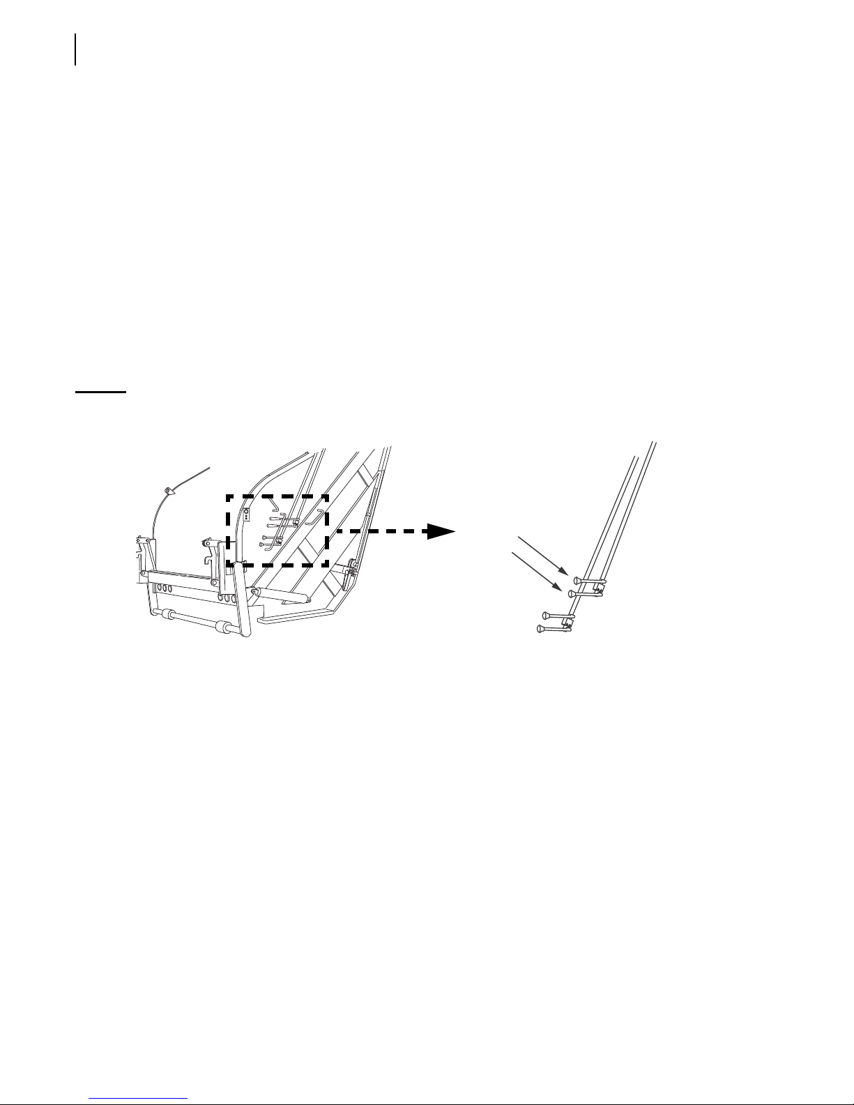
52 Controls, Indicators and Processes
Compaction Cycle
Both the packer panel lever and the carrier panel lever are shifted simultaneously inward to open the
packer panel and lower the carrier panel to the “interrupted cycle” position. Both levers are shifted
outward to sweep the load from the hopper and pack it against the pushout panel. Any time the
carrier panel lever is shifted, the engine speed-up automatically engages. The packing cycle may be
stopped at any point by moving both operating levers to neutral. The packer or carrier panel can be
moved independently.
Container Handling Control Levers (optional)
These control levers are provided when container handling attachments (drum winch, reeving
cylinder or container push bar) are added to the unit. They are used to raise and lower the container
causing the refuse to be deposited into the hopper for compaction. The levers are located on the right
side of the tailgate directly above the packer and carrier panel control levers (see Figure 3-15). A
refuse vehicle may have none or one or two control levers, depending on the configuration of the unit.
Figure 3-15
Container handling control levers
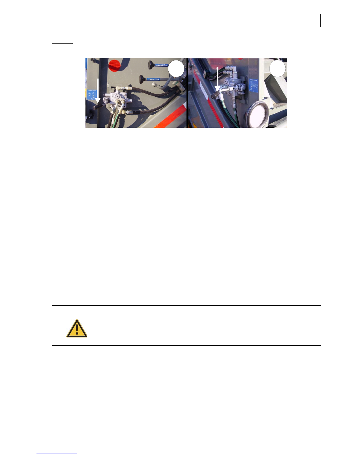
Tipper Lever (optional)
If one or two cart tippers are installed on the hopper sill, a tipper control valve is provided and
mounted on the right side of the tailgate near the hopper (see Figure 3-16). A second control valve
may also be mounted on the left side of the tailgate (see Figure 3-16).
Tipper Control on Tailgate Right Side
Move the tipper lever to the left to lift the cart.
CONT AINER
HANDLING
CONTROL
LEVERS
Move the tipper lever to the right to lower the cart.
Tipper Control on Tailgate Left Side
Move the tipper lever to the right to lift the cart.
Move the tipper lever to the left to lower the cart.
Page 61
Controls, Indicators and Processes 53
Figure 3-16
Tipper lever on tailgate right side (1), on tailgate left side (2)
1
Terms You Will Need To Know
The main purpose of a refuse body is to load, compact, transport and unload refuse. To assist in
loading of refuse in containers, various container handling systems are available to be mounted on
2R-II™ rear loaders.
A refuse container may be a mobile residential one (1) cubic yard container with casters or a ten (10)
cubic yard stationary commercial container. The equipment required to lift and empty these
containers will vary according to the container’s type and size.
Before going further, become familiar with the container handling terms you will need to know.
2
Container Attachment
The 2R-II™ Container Attachment System consists of a loading edge with a latch assembly and a
guide ear on each side of the tailgate. The latches and ears are installed to accommodate containers
from one (1) to ten (10) cubic yard capacity. The standard container for use with the 2R-II™ rear
loader must have an ANSI Standard 1 ¼” - 1 ¾” diameter trunnion bar, with a 77 ½” to 78” end-toend distance. This trunnion bar will center the container between the “ears” and prevent it from
moving sideways. The latch arms must be manually raised and secured by the arm upper latch. The
latches and ears, when properly used, will efficiently secure the container to the tailgate while
dumping.
Warning!
Only containers that meet the American National Standards Institute (ANSI) regulations
should be used in conjunction with the 2R-II™ Container Handling Systems.
Page 62
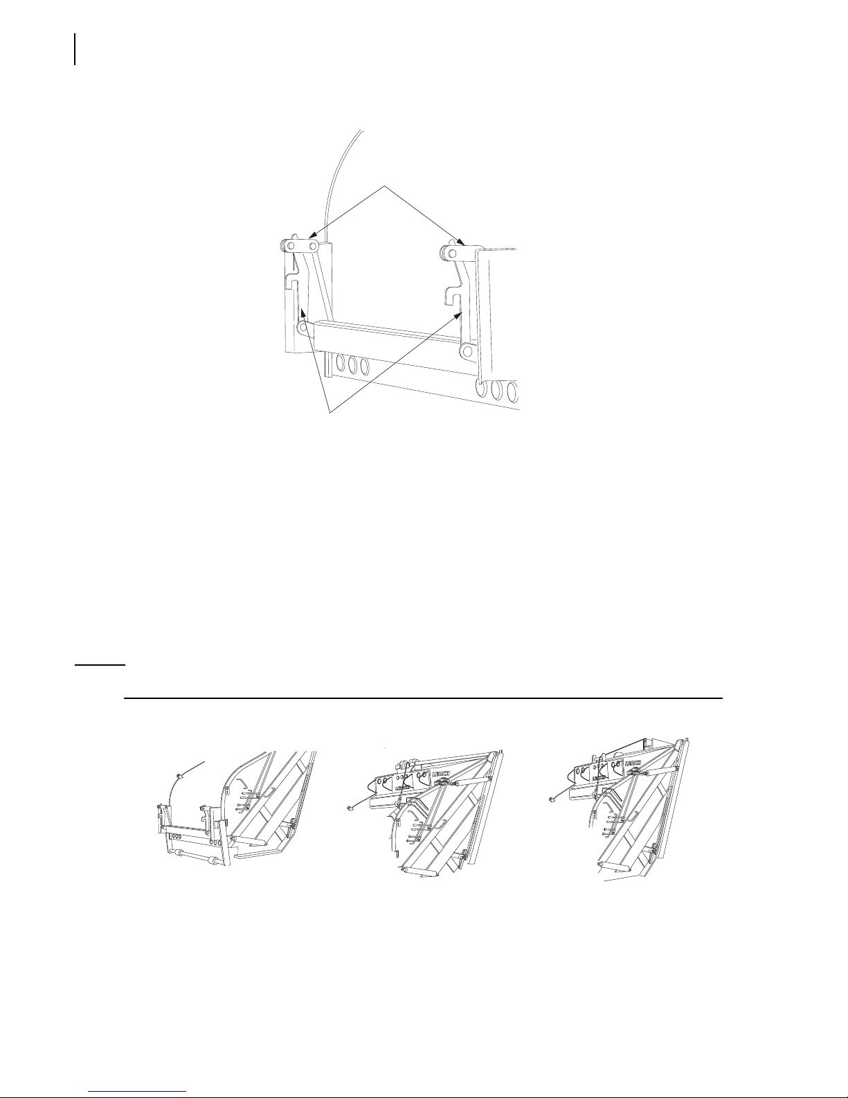
54 Controls, Indicators and Processes
ARM LATCH
ARMS
Container Handling Systems
To lift or dump a container, several systems are available.
The following are some handling systems that could be used:
A hydraulically operated container push bar for containers of 1 to 3 cubic yard capacity.
A drum winch or roof-mounted container lifting cylinder for containers with capacities of four (4)
or more cubic yards.
Drum winches are rated at various pounds of pull. The 2R-II™ drum winch and lifting cylinder are
rated at 12,000 lbs.
NOTE: Leach
PUSH BAR
TM
bodies can be equipped with more than one container handling system.
DRUM
WINCH
LIFTING
CYLINDER
Page 63
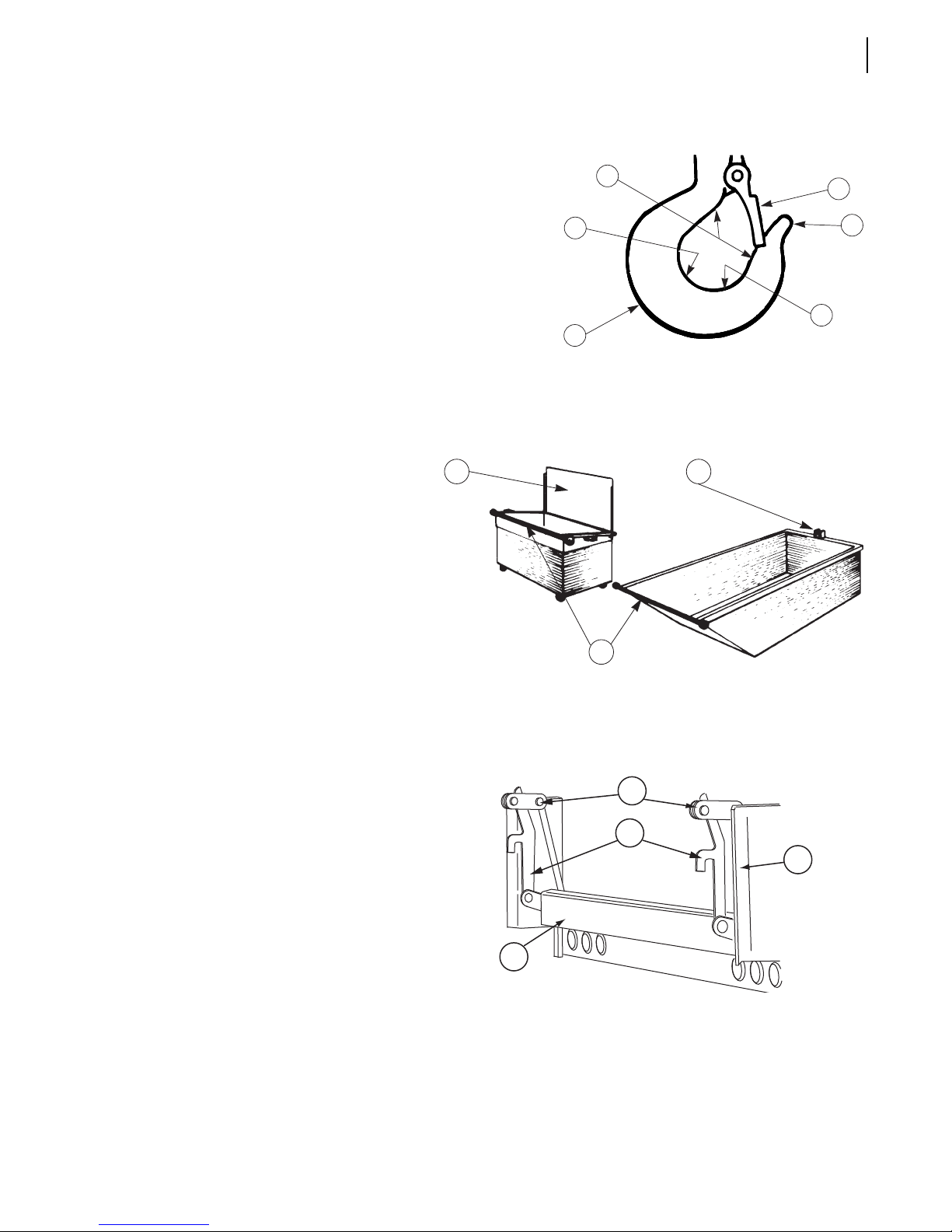
Hook
1. Throat Opening
2. Back
Controls, Indicators and Processes 55
1
4
3. Heel
4. Hook Safety Latch
5. Tip
6. Base
____________________________
Container
1. Trunnion Bar
2. Hook Attachment
3. Lid
2
3
3
1
2
5
6
____________________________
Container Attachment
1. Loading Sill
2. Arm
3. Latch
4. Guide Ear
____________________________
3
2
4
1
Page 64
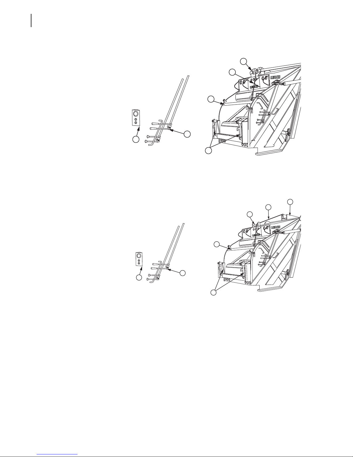
56 Controls, Indicators and Processes
()
Winch
1. Control Levers
2. Engine Speed-Up Button
3. Winch Lifting Cable
4. Winch Assembly
5. Container Attachment
6. Stop Bar/Lid Guard
2
____________________________
Container Lifting Cylinder (CLC)
1. Control Levers
2. Engine Speed-Up Button
3. Cylinder Cable Roller Guide
4
3
6
1
5
5
4
3
4. Cylinder Cable
5. Lifting Cylinder Assembly
6. Container Attachment
7. Stop Bar/Lid Guard
____________________________
7
1
2
6
Page 65
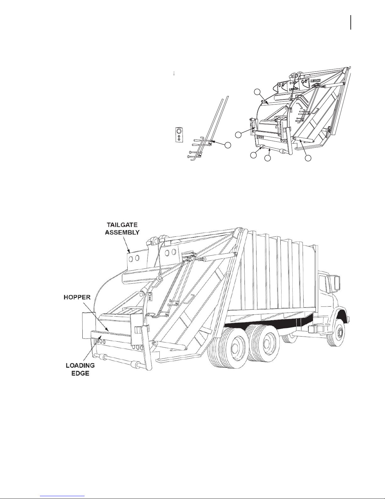
Container Push Bar (CPB)
1. Control Levers
2. Push Bar
Controls, Indicators and Processes 57
(CPB)
3. Lift Roller
5
4. Push Bar Cylinders
5. Stop Bar/Lid Guard
6. Container Attachment
6
1
3
2 4
Other Terms You Will Need To Know
Page 66
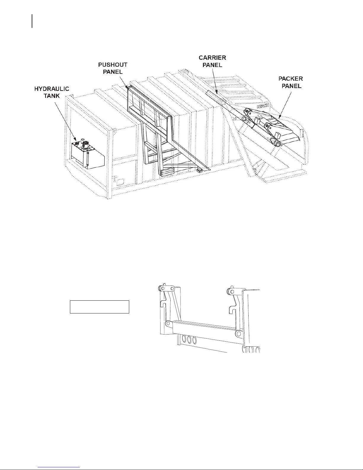
58 Controls, Indicators and Processes
Container Handling Process
All LeachTM container handling systems have three (3) basic operation steps:
Attaching
The first step in container handling is to attach the container to the rear loader by securing it with the
latch arms of the container attachment.
Attaching container
Page 67
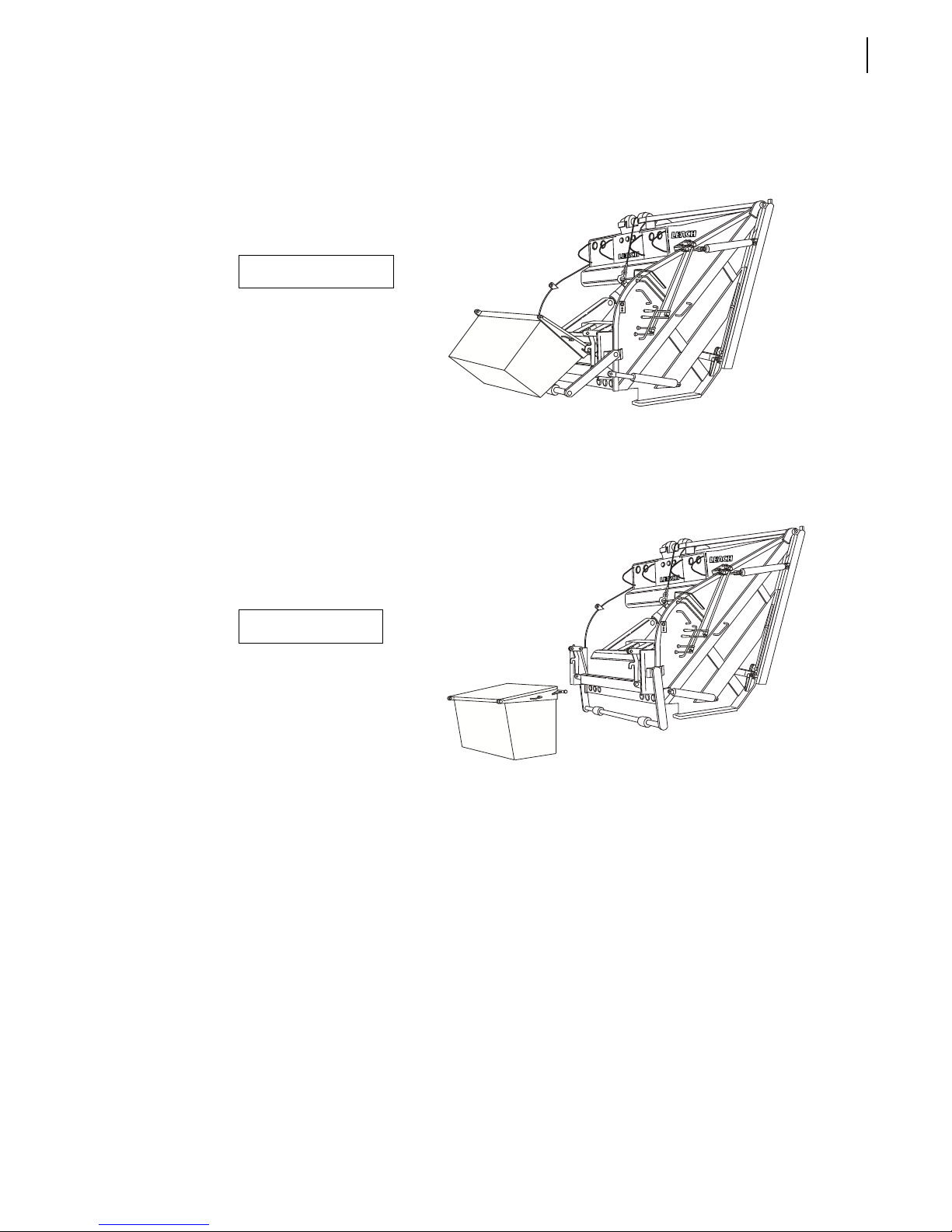
Dumping
A container handling system is used to raise the container and empty its content into the hopper of
the rear loader.
Releasing
When the container is empty, it is lowered to the ground, the latch arms released and the truck is
moved forward.
Controls, Indicators and Processes 59
DUMP
Dumping container
ground,
forward.
Releasing container
ECT
Waste Handling Process
The main purpose of the 2R-II™ is to safely and efficiently load, pack, transport and unload refuse.
The following describes how the unit performs those tasks in the most basic terms. For a more
detailed description of the unit and its components, refer to the 2R-II™ Maintenance Manual. Before
going further, take a look at the following illustrations. They will help you understand the
fundamentals of the waste handling process and how they relate to one another.
Loading
Refuse is first loaded into the hopper of the tailgate assembly. The carrier and packer panels, which
sweep up and pack the refuse from the hopper, will be in the “home” position.
Page 68
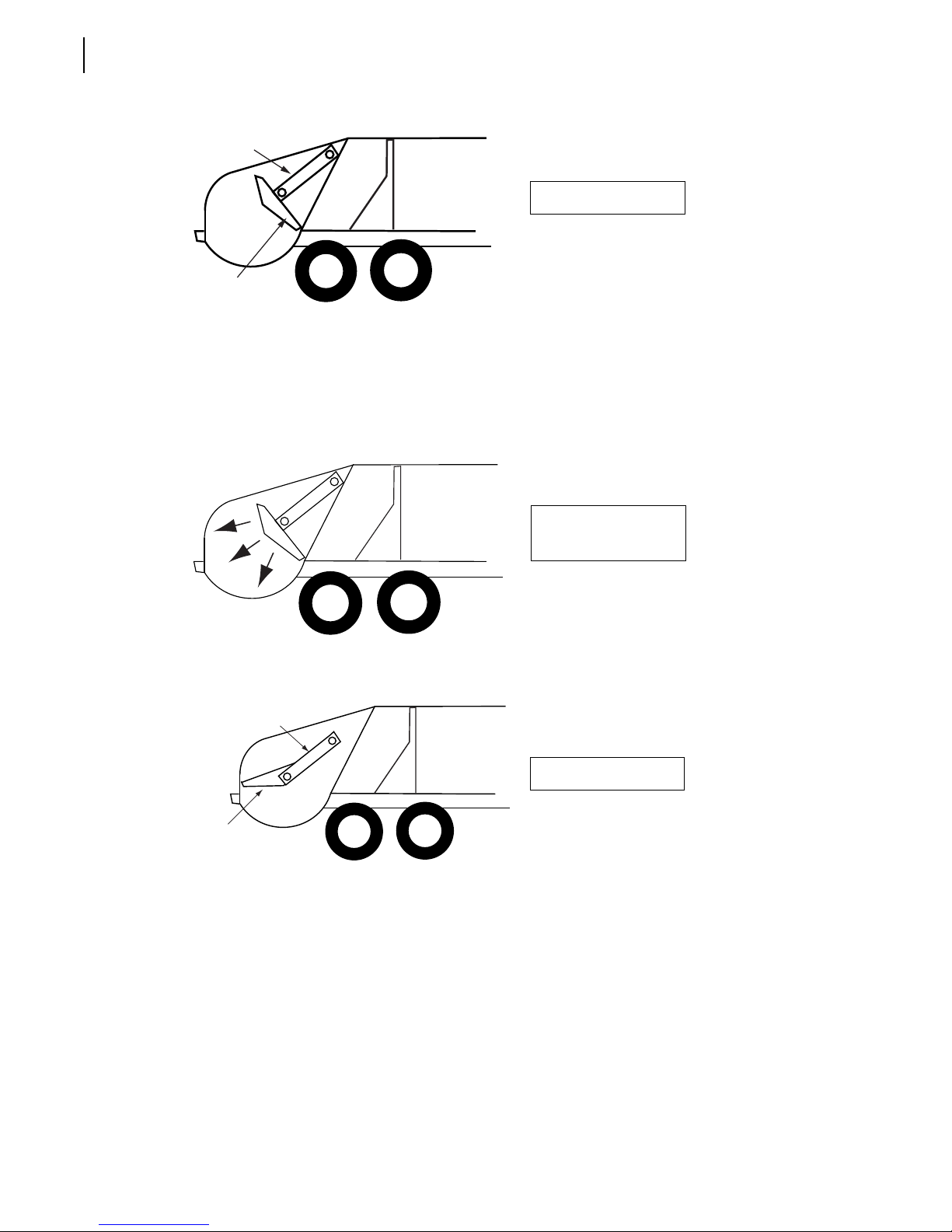
60 Controls, Indicators and Processes
CARRIER
PANEL
PACKER
PANEL
Packing
When the operator starts the packing cycle, the carrier and packer panels move rearward over the
load.
“Home” position
Carrier and packer
panels move over load
Next, the carrier and packer panels automatically stop at the “interrupted cycle” position.
CARRIER
PANEL
“Interrupted cycle”
PACKER
PANEL
The operator again activates the packing cycle. The carrier and packer panels move forward and
sweep the refuse from the hopper up into the body and pack it against the pushout panel. Having
completed a cycle, the carrier and packer panels are back into the “home” position and the hopper is
cleared for more refuse.
Page 69
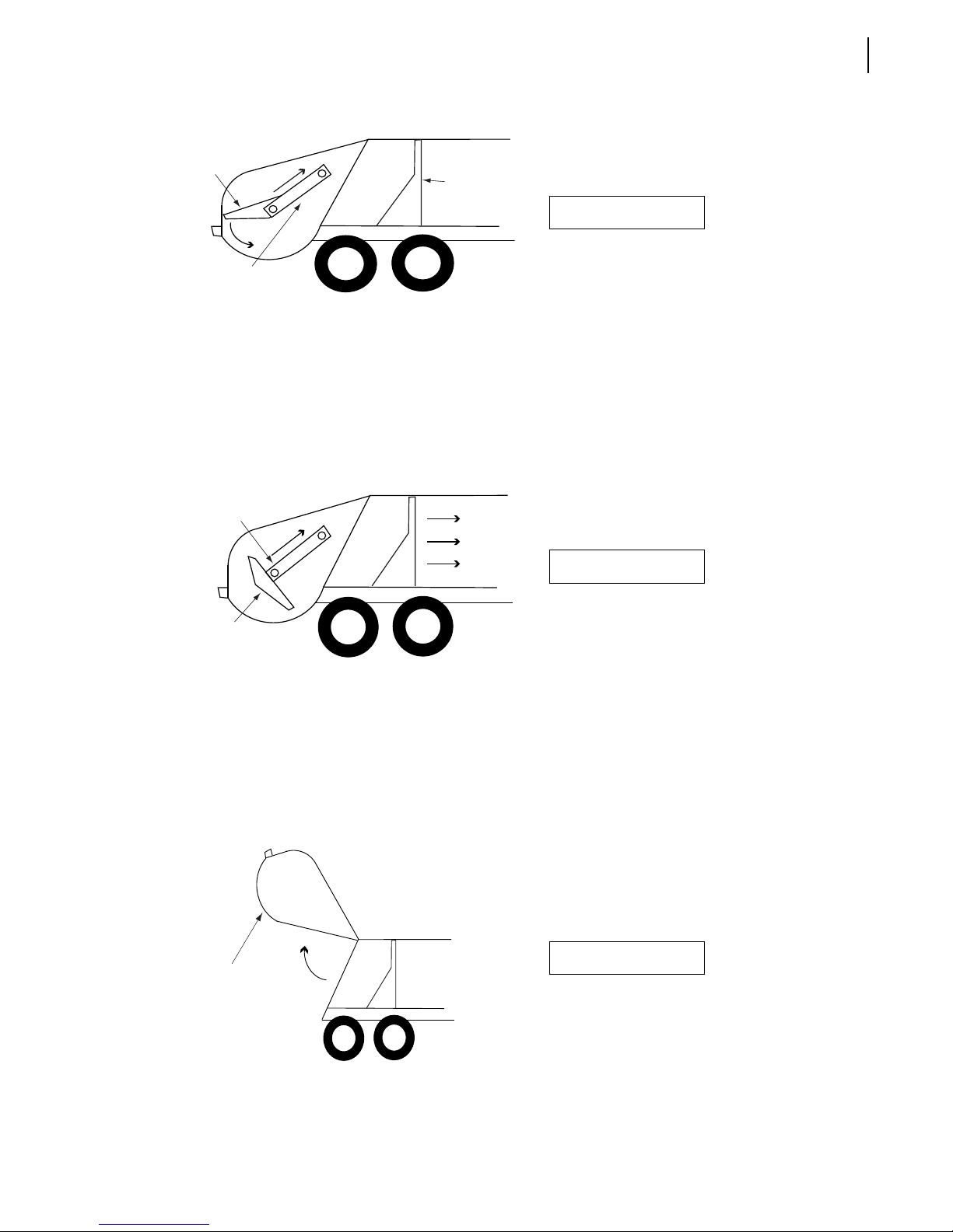
Controls, Indicators and Processes 61
PACKER
PANEL
CARRIER
PANEL
PUSHOUT
PANEL
Packing position
Also, during the packing cycle, considerable hydraulic pressure is applied to the cylinders which
control movement of the carrier and packer panels. This causes the refuse to be compacted tightly
allowing for a large carrying capacity.
On units with the standard clamp pushout system, the operator must manually release the pushout
panel clamping system to allow movement of the pushout panel.
Once the body is full, the 2R-II™ can be moved to the dumpsite for unloading.
CARRIER
PANEL
PUSHOUT
PANEL
PACKER
PANEL
Unloading
At the dumpsite, the unit is unloaded in two easy steps:
1. The tailgate is raised by the operator.
2. The pushout panel is moved to the rear of the body, pushing out the load.
TAILGATE
Pushout panel moves
forward
Tailgate raised
Page 70
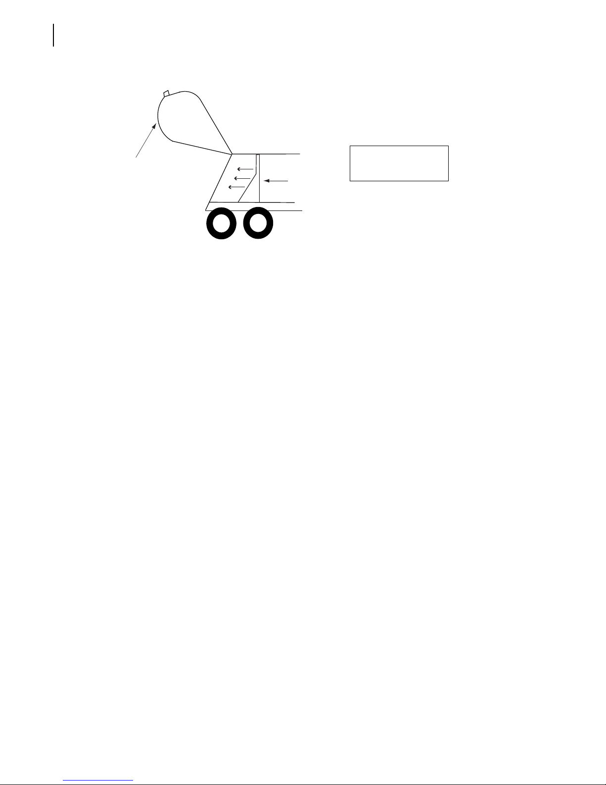
62 Controls, Indicators and Processes
A
TAILGATE
EARWARD
D
After unloading, on telescopic units, the tailgate is lowered and “latched” to the body.
On clamp style units, the pushout cylinder is retracted and then the clamp is set by extending the
cylinder a couple of inches. The tailgate is then lowered and “latched” to the body.
PUSHOUT
PANE L
Pushout panel moves
rearward ejecting the
load
Page 71

Operating the 2RII™
The different methods, procedures and necessary
actions to operate the 2R-II™ are presented in this
section.
4
Warning!
Before operating the 2R-II™, the operator must be
completely familiar with all safety procedures, and the
location, operation and functions of all controls and
indicators related to the operation of the unit.
You must complete the daily inspection before starting
the vehicle. It is your responsibility to report any
malfunctions or concerns to your supervisor and
maintenance personnel.
Consult with your supervisor for specific rules of
driving the 2R-II™.
Obey all speed restrictions and regulations.
Pre-Operating WalkAround Inspection
Always read and understand the
Operator’s Manual before operating the
unit.
Each day, before starting the unit, perform the
following “walk-around” inspection.
Make sure all decals are in place and readable.
Replace any decals that are not. Refer to “Safety
and Informative Decals” on page 16 for a list of
decals.
NOTE: A decal kit is available from your local authorized
Labrie distributor.
As you are checking for decals, also look for fluid
leaks on and around the unit. Check for fluid leaks
at the hydraulic cylinders, valves and fittings.
Page 72

64 Operating the 2R-II™
Inspect the mounting sills and attaching hardware. Make sure everything is tight and that there are
no broken or excessively worn parts. Check capscrews and fasteners for looseness, visible welds
for cracks and control levers for each movement.
Make sure the tailgate clamps are in the closed position and securely tightened (see Tailgate
Clamps on page 50). If the optional hydraulic tailgate-locking mechanism is used instead of
tailgate clamps, make sure this mechanism has been engaged to the locked position.
NOTE: When the tailgate is unlocked, both locking mechanism cylinders are retracted. They are
extended when the tailgate is locked.
Check the hydraulic tank gauge to make sure the fluid is in the “safe” range. Add fluid, if necessary.
The pushout cylinder must be retracted, the tailgate down, the carrier and packer panels in the
“interrupted cycle” position to check the hydraulic fluid level.
Make sure all operating levers are in the neutral position.
Check:
• Packer panel lever (see Figure 3-14)
• Carrier panel lever (see Figure 3-14)
• Pushout lever (see Figure 3-11)
• Tailgate lever (see Figure 3-11)
Caution!
Warning!
Start the truck according to the chassis manufacturer’s instructions and while it is warming up,
continue the walk-around inspection.
Check all of the operating and running lights. Make sure none are missing and that there are no
burned-out bulbs.
Warning!
Never operate the 2R-II™ with any part of the control system or levers removed or serious
damage will result.
Never under any circumstances enter the body if the truck is running. Open the packer panel
and release the pushout panel clamp before entering the body. Always make sure the truck
engine is off and the keys are in your pocket before entering the body (see Locking Out and
Tagging Out the Vehicle on page 38).
The TAILGATE OPEN warning light should be off. Do not operate the unit if the light is
illuminated.
With the engine running, the speed-up switch ON, the PTO/pump switch engaged, the
transmission in neutral and the brakes applied, depress the speed-up push-button on the forward
left (street) side of the body (see Figure 3-11). You should hear the engine speed-up.
Page 73
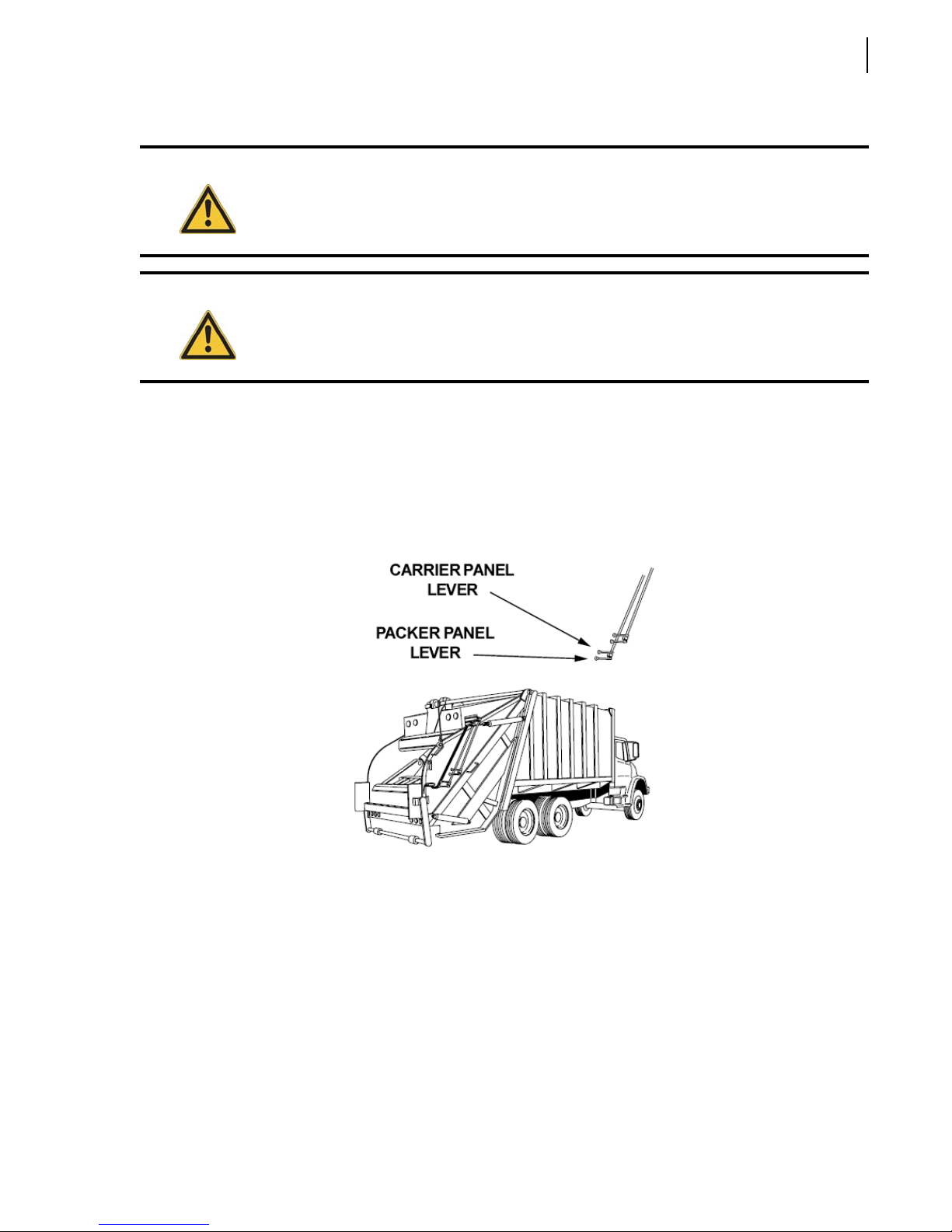
Operating the 2R-II™ 65
Danger!
Caution!
Move both the packer panel lever and carrier panel lever inward and let go. Check for the
following:
• Engaging the carrier panel lever will activate an engine speed-up switch; you should hear the
engine speed-up.
• Observe the carrier and packer panel movement; it should be smooth. The panels should stop
automatically at the “interrupted cycle” position.
Never place hands in or near the packer panel during operation.
Never hold the packer or the carrier panel lever in position by hand. Always engage and let
go immediately. The only exception is at the end of a load.
Move both the packer panel lever and carrier panel lever outward and let go. Observe the carrier
and packer panel movement; it should be smooth. The panels should stop automatically at the
“home” position.
Depress the two driver signal push-buttons located on both sides of the tailgate to make sure that
the audible alarm located in the cab is working (see Figure 3-13).
Back the unit up a few feet to ensure that the backup alarm is working properly.
Loosen the tailgate clamps and swing them out (see Figure 3-12). Raise the tailgate approximately
6” and check to see if the T
audible. (Do not have the unit in reverse.)
AILGATE OPEN light on the dash is on and if the backup alarm is
Page 74
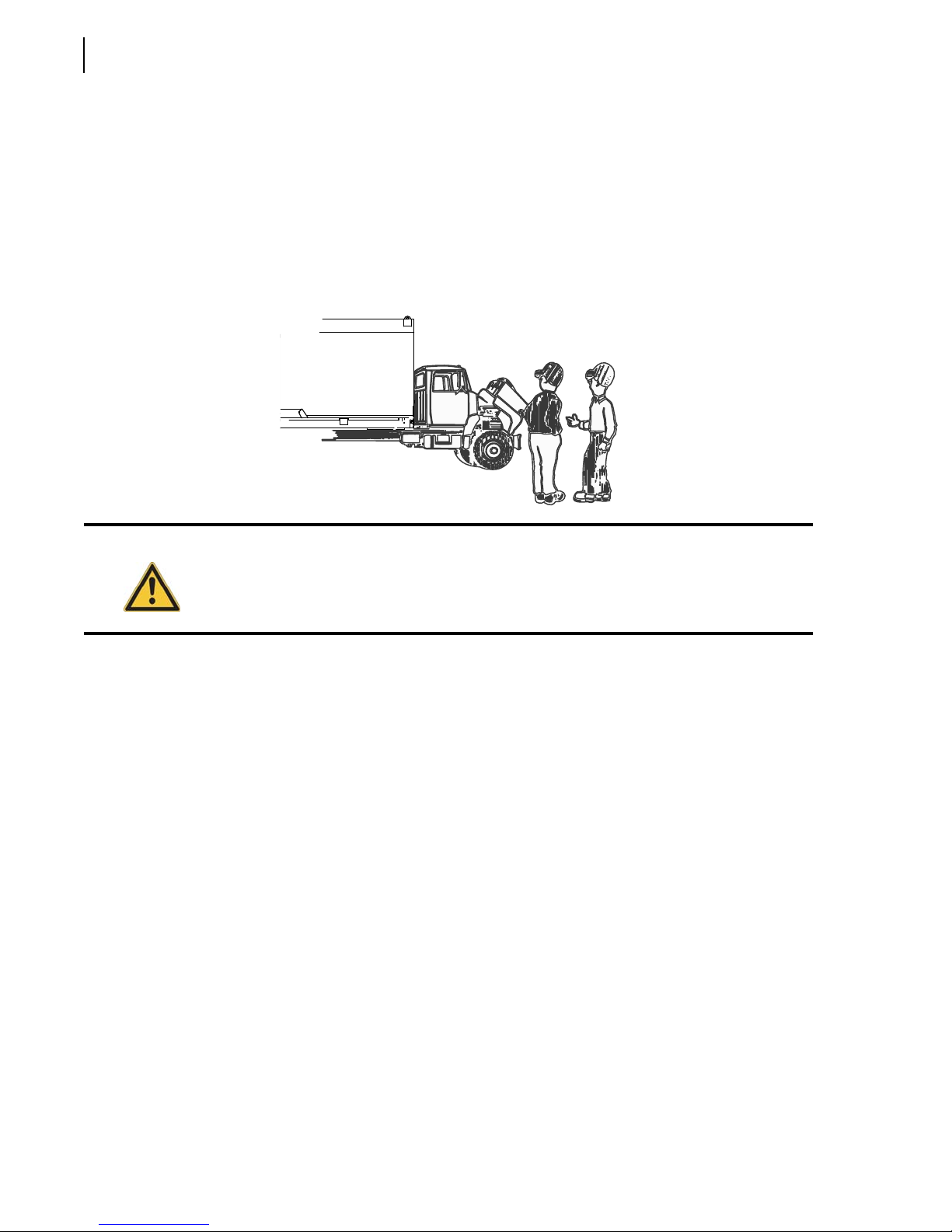
66 Operating the 2R-II™
On units with a hydraulic locking mechanism, unlock the tailgate first before attempting to open
the tailgate. Use the locking/unlocking controls (see Figure 2-9) on the forward left side of the
body to lock/unlock the tailgate.
Report any problems found during the pre-operation “walk-around” inspection to the
maintenance supervisor for service or repair, place a tag on the steering wheel, using a nonreusable fastener, stating the unit is inoperative and remove the keys (see Locking Out and Tagging
Out the Vehicle on page 38).
Warning!
Do not operate a unit that is in need of service or repair.
Walk-Around Inspection Checklist
Decals in place and readable.
Look for any fluid leaks.
Mounting hardware tight and in place.
Tailgate clamps closed and tightened.
Or, hydraulic tailgate-locking mechanism engaged.
Hydraulic fluid reservoir at correct level.
All operating levers in neutral positions.
Pushout panel area clear of debris.
Engine warmed up according to manufacturer’s instructions.
All operating and running lights functioning.
Engine speed-up buttons operational.
Packing cycle operates properly.
Driver signal alarm can be heard.
Back-up alarm and T
AILGATE OPEN light are operable.
Report any problems to proper personnel.
Page 75
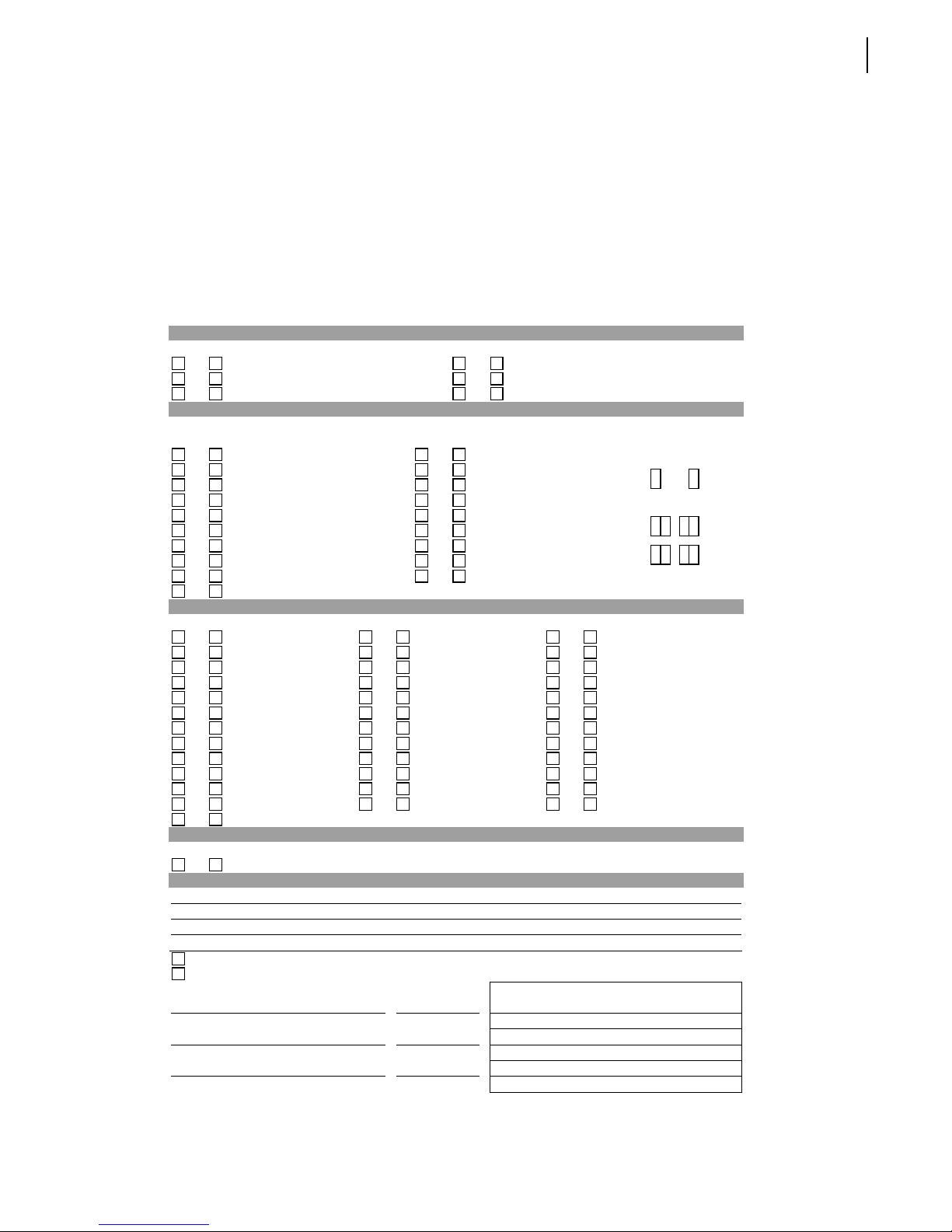
Inspection Sheet
The following is an example of an inspection sheet. The operator MUST follow the inspection sheet
provided by his employer. If the employer does not have an inspection sheet, ask for their permission
before using this example sheet.
VEHICLE CONDITION REPORT
Date: _________________ Unit: _______________________________
Driver: ____________________ Demo: _______________________
Engine Hrs in: _______________ Engine Hrs out: __________________
Mileage in: _________________ Mileage out: ____________________
Start Time: _____________________________ Finish Time: _____________________________
Operating the 2R-II™ 67
PRE POST Amount Added PRE POST Amount Added
Engine Oil Qt. _______ Fuel Gal. ________
Hydraulic Oil Qt. _______ Transmission Qt. _________
Coolant Qt. _______ Water Qt. _________
If items need repair, check below and describe. TIRES
PRE POST PRE POST Indicate any defects.
All gages/gage lights Cab horn
Low oil pressure Exterior back-up horn
Low oil warning light/buzzer Windshield cracks
Seat and seat belt Windshield wipers
Clutch free play (Juggler) Heat/Defrost
License/registration papers Reflective triangles
Service brakes adjusted Steering play
Parking brakes operational Radio
Low air warning light/buzzer Camera
Air compressor adequate
VISUAL BODY WALK-AROUND
PRE POST PRE POST PRE POST
Battery disconnect Electrical wiring Compactor working
Body damage Fire Extinguisher Hydraulic leaks
Cab damage Fuel tank/lines Hydraulic pressure
Air lines Exhaust Hydraulic hoses
Air compressor Engine Wheel/Rims
Air dryer Starter Seals
Head lights Turn signal Transmission
Marker lights Camera Mirrors
Brake lights Cable/Hooks Radiator
Suspension Arm Safety devices
Hopper clean Body clean Safety decals
Tailgate Packer Cart tipper
Safety Interlock switches
FLUID LEVELS
CAB INSPECTIONS
PRE POST
No Defects – Vehicle Condition Satisfactory
Above defects corrected
Above defects need not be corrected for the safe operation of vehicule.
DRIVER’S SIGNATURE DATE
DISTRIBUTOR SIGNATURE DATE
DRIVER’S REVIEW SIGNATURE DATE
DEFECT DESCRIPTION
Mechanic’s Comments :
Page 76
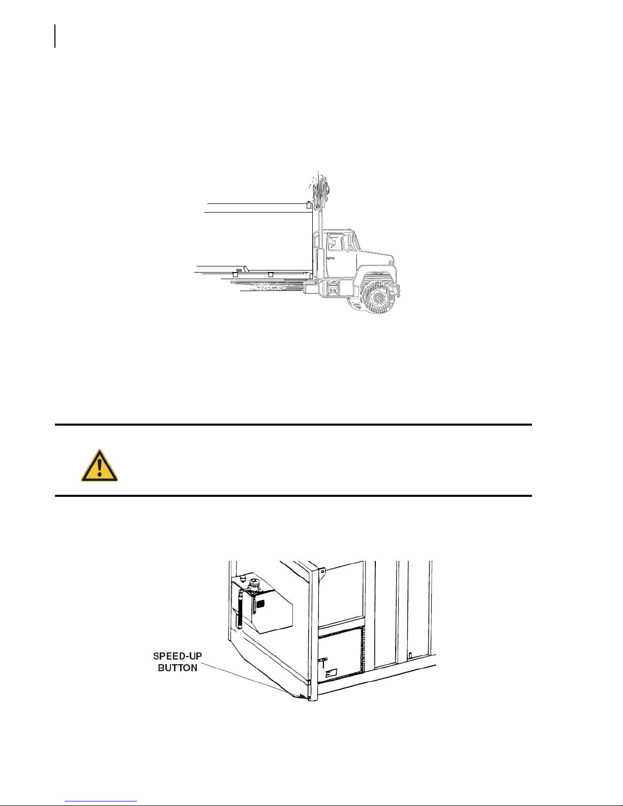
68 Operating the 2R-II™
Operating Instructions
Starting Up
1. Inspect and start the truck as described in the pre-operational “walk-around” inspection.
2. Engage the Pump/PTO switch (to start the hydraulic pump) [see Pump Switch on page 44].
3. Place the Engine Speed-Up switch in the ON position (see Engine Speed-Up Switch on page 44).
Positioning the Pushout Panel
To load the unit, the pushout panel must be positioned toward the rear of the body.
Caution!
To position the pushout panel correctly:
1. Depress and hold the speed-up push-button.
Check the tailgate clamps to make sure both are securely tightened (see Figure 3-12). On
units with a hydraulic tailgate-locking mechanism, make sure the tailgate is properly locked.
Both tailgate cylinders must be extended (see Figure 2-10).
2. Push the pushout lever rearward until the pushout cylinder is fully extended.
Page 77
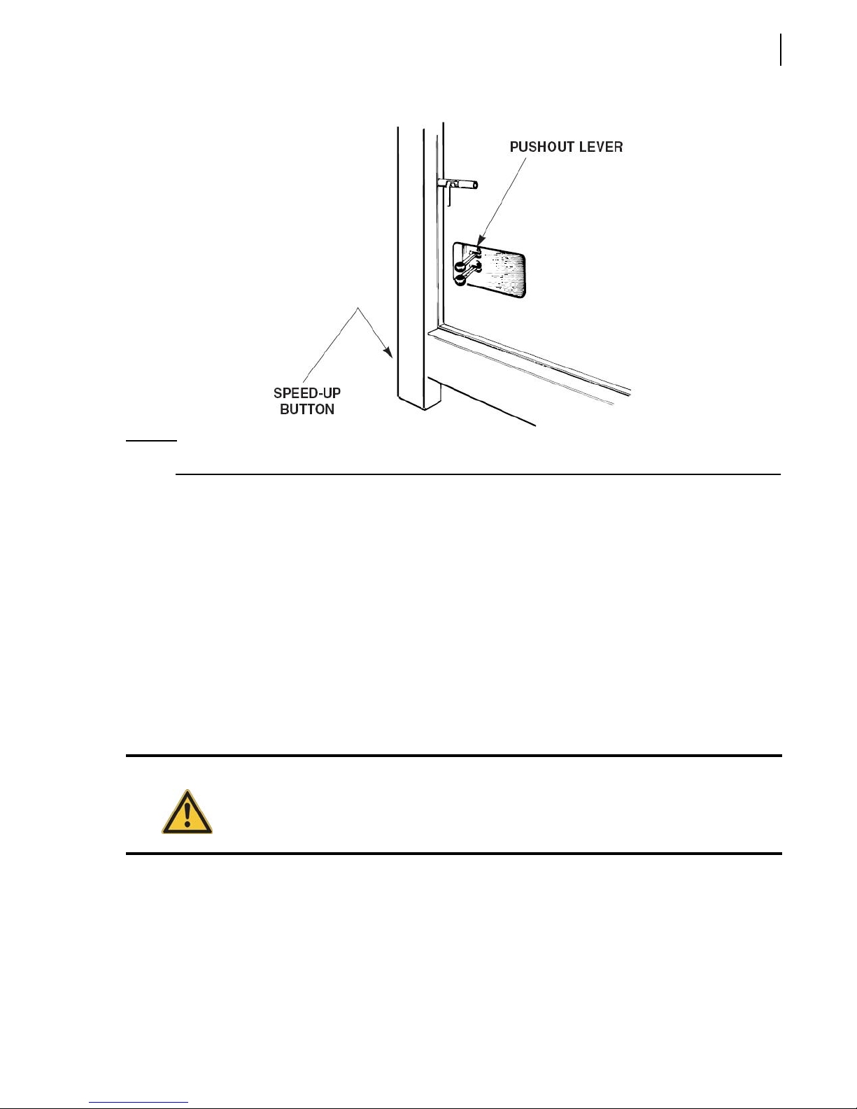
Operating the 2R-II™ 69
NOTE: On units with a telescopic pushout cylinder, the pushout panel is now in position for loading.
3. Release the speed-up button and pull the pushout lever forward until the pushout cylinder is fully
retracted.
4. Repeat steps 2, 3 and 4 until the pushout panel is as far back as it will go and then pull forward on
the pushout lever to fully retract the pushout cylinder. Now extend the cylinder a few inches to
reset the clamp.
Loading the Hopper
There are only a few but important points to remember during loading of refuse:
Load the hopper evenly on both sides.
Load heavy objects in the center of the hopper.
Do not load refuse higher than the loading edge.
Warning!
Always follow proper loading procedures.
Attaching a Container to the Tailgate
Place the container on a flat, level surface. For large non-moveable containers the driver should back
the unit toward the container following all vehicle and refuse body safety restrictions.
Page 78
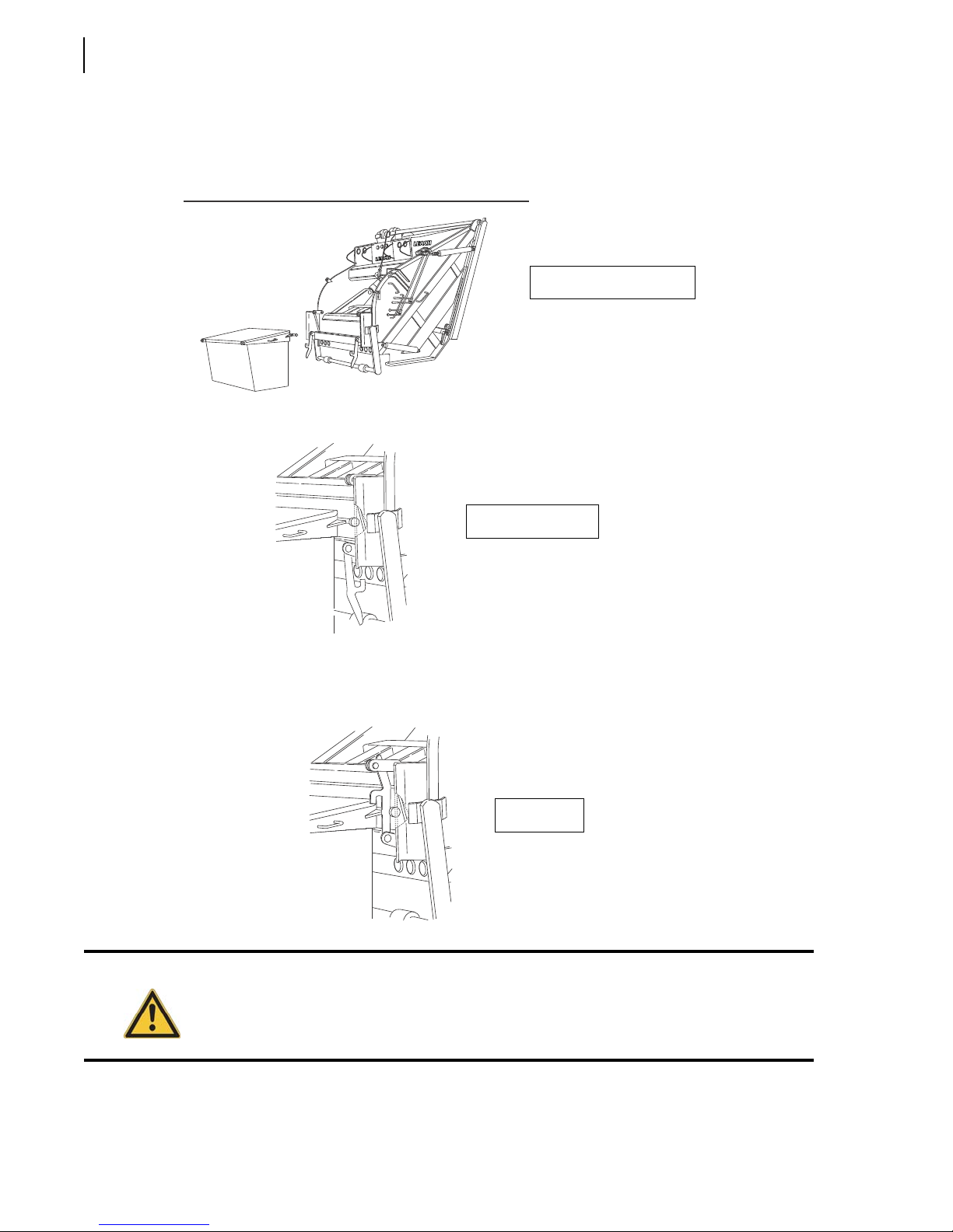
70 Operating the 2R-II™
The vehicle should be backed with the latch arms open until the container trunnion bar (see
Container on page 55) is between the guide ears (see Container Attachment on page 55) and within
the latch assembly. Center the container on the attachment.
CKER
Attaching container
Arms unlatched
After setting the vehicle parking brake, the right and left container latch arms must be engaged.
Attached
Warning!
Lifting a container without both latch arms properly secured can allow the container to
swing away from the unit and cause severe injury or death.
Page 79
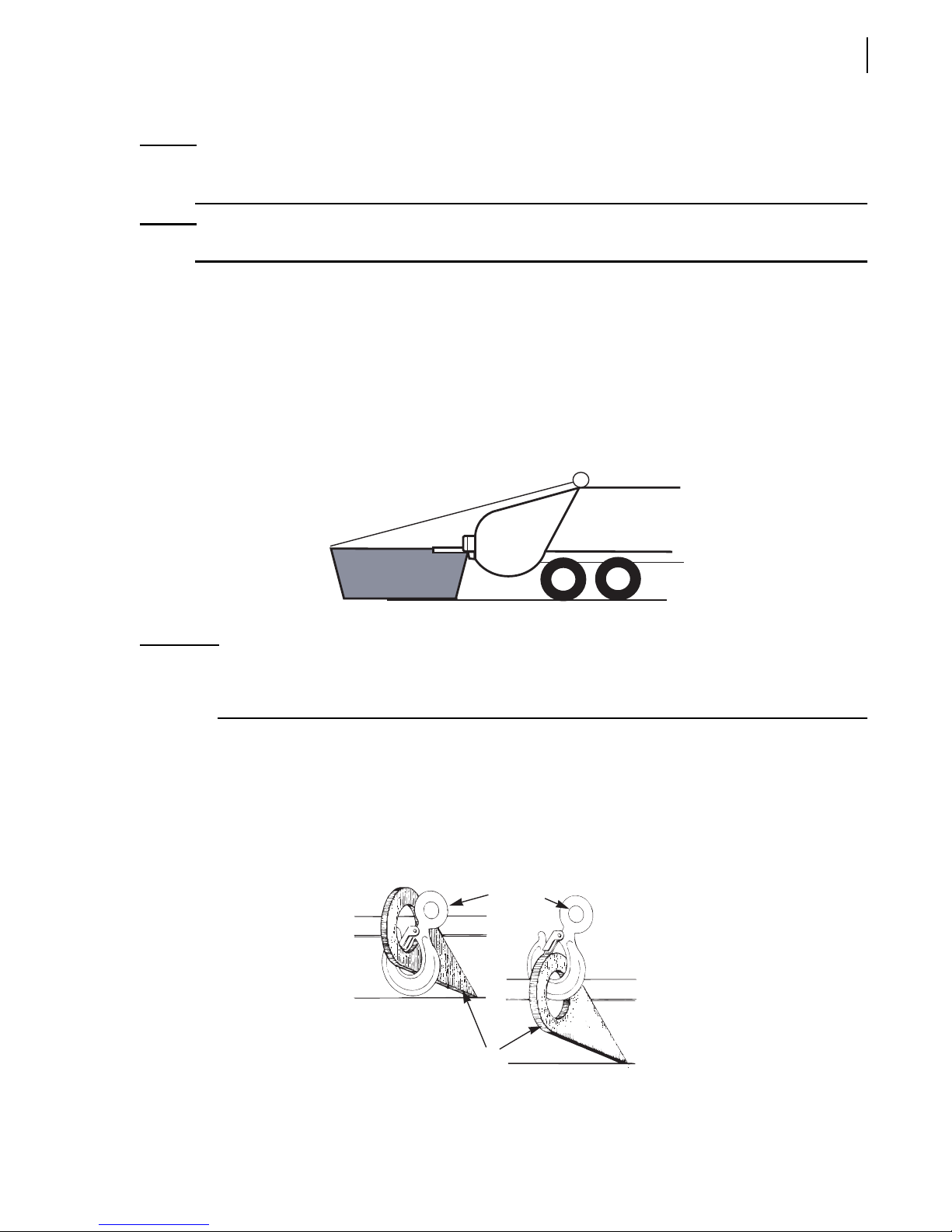
Operating the 2R-II™ 71
NOTE: If the container is equipped with wheels, it should be rolled into position only after the vehicle
parking brake has been set.
NOTE: Even small containers must be secured to the tailgate with the latch arms.
Using a Winch or a Container Lifting Cylinder
Once the container is secured within the latch assembly, the lifting cable should be attached. Place
the load in the base of the hook with the safety latch closing the throat opening (see Hook on
page 55).
ATTACH CONTAINER
LOWER TO CHECK CONTENT
IMPORTANT: Hooks must be used in a proper manner. Proper use of a lifting hook not only includes placing the
load in the base of the hook, but also includes ensuring that the hook is lifting on the proper area of
the attachment point.
The hook must completely encircle the attachment point. Equally as important, at the time load is
applied to the base of the hook, the positioning must be correct to prevent the hook from dislodging.
When using an eye type attachment point the base of the hook must be positioned to lift on the inside
of the eye. The following illustration shows both correct and incorrect positioning of the hook.
INCORRECT
CORRECT
HOOK
ATTACHMENT
POINT
Page 80
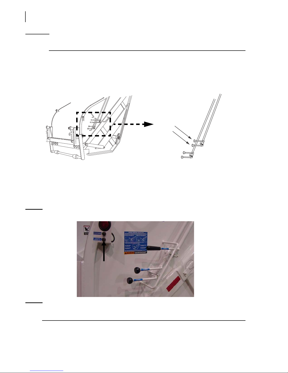
72 Operating the 2R-II™
IMPORTANT: For safety reasons, make sure the hook is positioned properly as slack is removed from the chain/
cable before lifting.
Slack should be removed from the cable, without the use of the engine speed-up button, by moving
the winch control lever in the direction shown on the instruction decal to raise the container. When
the cable is tight, the speed-up button (see Figure 4-1) should be depressed and held to provide
sufficient hydraulic power to lift the container.
CONTAINER
HANDLING
CONTROL
LEVERS
The container should be raised until the contents begin to slide into the hopper of the packer or until
it is resting against the container bump bar.
Do not overfill the hopper. After assuring that all persons are standing clear lower the container to
check the load condition of the container and the hopper. Lower the container enough to see
between the container and the tailgate while standing on the ground without placing yourself
between them.
Figure 4-1
Engine speed-up button
NOTE: On units with a roof-mounted container lifting cylinder, the speed of the device is limited
during both the up and down movement. This speed reduction is for safety considerations.
When the hopper is full, lower the container to the ground, assure all persons are standing clear and
then engage the packer mechanism (see Packing the Load on page 73).
Page 81
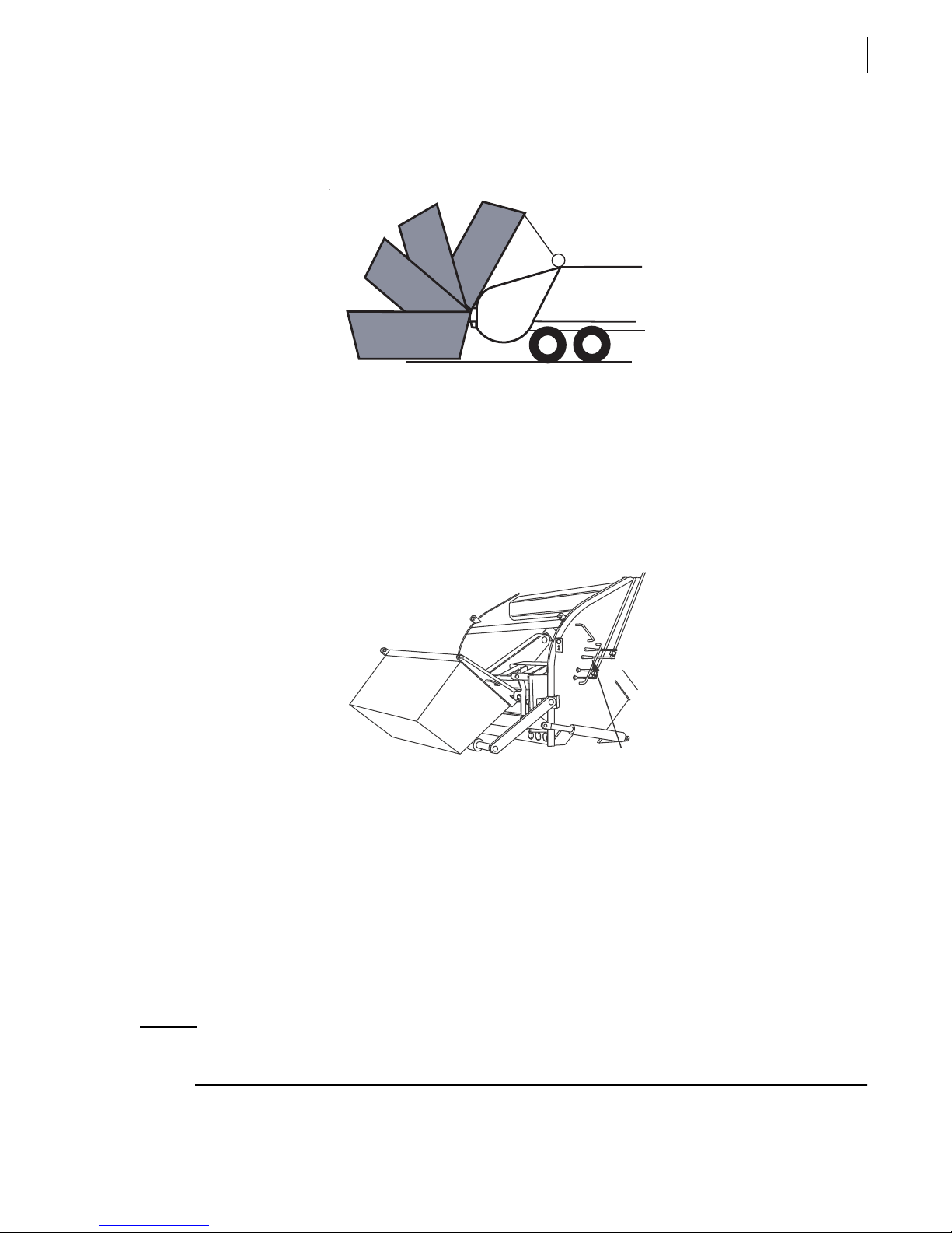
After the packer panel has passed the loading sill, the container may be raised to again fill the hopper.
Repeat this process until the container is empty.
Using a Container Push Bar (CPB)
Once the container is secured within the latch assembly the container is ready to be dumped. After
assuring that all persons are standing clear, the operator moves the CPB control lever in the direction
shown on the instruction decal to raise the container. When raising a container with the push bar, it is
normal for the container to first lift upward within the container latch assembly, then tip toward the
hopper and finally lower or drop to the bottom of the latch slots.
LOWER TO
GROUND
Operating the 2R-II™ 73
CONTAINER
CONTROL
LEVER
Do not overfill the hopper. After assuring that all persons are standing clear lower the container to
check the load condition of the container and the hopper. Lower the container enough to see
between the container and the tailgate while standing on the ground without placing yourself
between them.
Releasing the CPB control handle when the container begins to tip will allow the container trunnion
bar to lower within the latch slots with ease.
Packing the Load
NOTE: The packing cycle can be stopped at any time by moving both the packer panel lever and the
carrier panel lever to the center (neutral).
Page 82
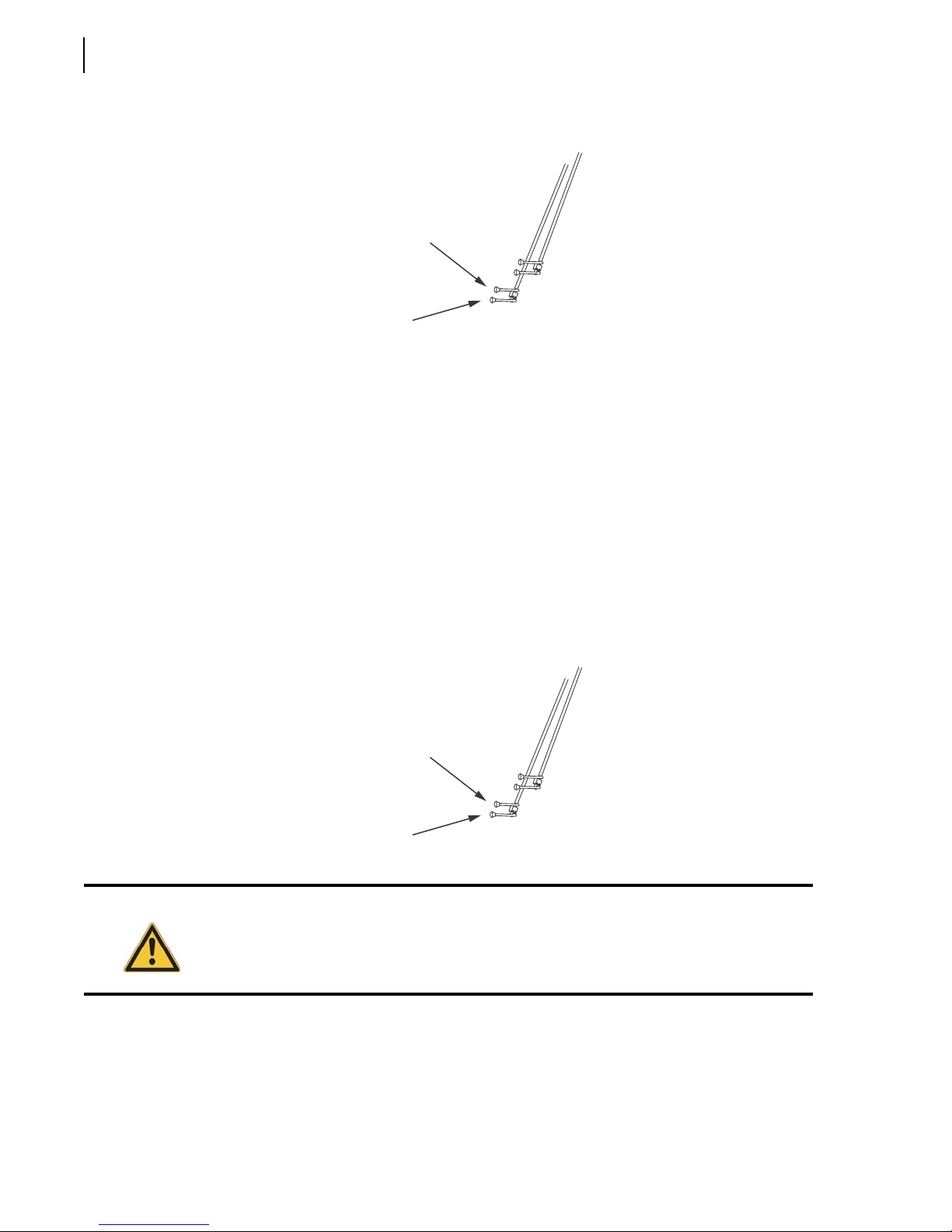
74 Operating the 2R-II™
To pack the load:
1. Cycle the packer panel and the carrier panel by moving both the packer panel lever and the
carrier panel lever inward, toward the tailgate, then let go.
The packer panel will open and the packer panel lever will automatically shift back to neutral.
The carrier panel will then move down to above the loading edge, stop in the “interrupted cycle”
position and the carrier panel lever will automatically shift back to neutral.
CARRIER
PANEL
LEVER
PACKER PANEL
LEVER
2. Move both the packer panel lever and the carrier panel lever outward, away from the tailgate,
then let go to finish the cycle.
The packer panel will sweep the hopper and the packer panel lever will automatically shift back to
neutral. The carrier panel will then move up into the body and stop in the home position and the
carrier panel lever will automatically shift back to neutral.
Warning!
CARRIER
PANEL
LEVER
PACKER PANEL
LEVER
Stand clear of the hopper area during the packing cycle!
3. Repeat steps 1 and 2 each time the hopper is filled to, but not above, the loading edge.
Page 83
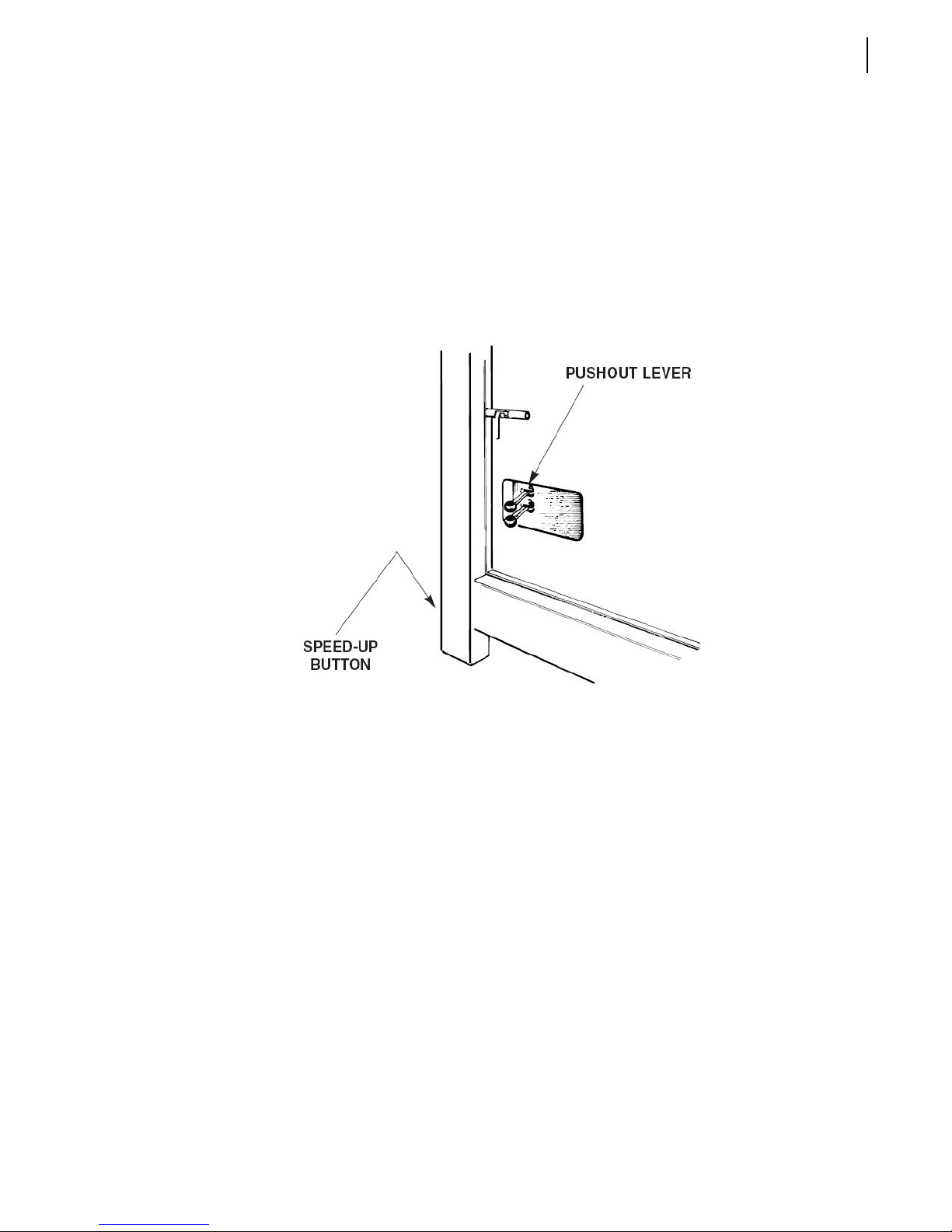
Pushout Panel Operation during Packing
The 2R-II™ telescopic pushout cylinder will normally move toward the front of the body
automatically. When the resistance circuit is adjusted to produce maximum load density, it may
become necessary to manually retract the telescopic pushout cylinder in order to allow the
compacted refuse to move forward in the body. Also, if the packer panel stops short of the “home”
position, the carrier panel operating lever may need to be held (overridden) to allow the refuse to
move the pushout panel toward the front of the body. When the pushout panel has reached the front
of the body, neither the packer panel operating lever nor the carrier panel lever should be overridden
except to clear the final hopper load.
Operating the 2R-II™ 75
Releasing the Container
Once the container is empty, it should be lowered to the ground, the latch arms released and the cable
disconnected.
Page 84
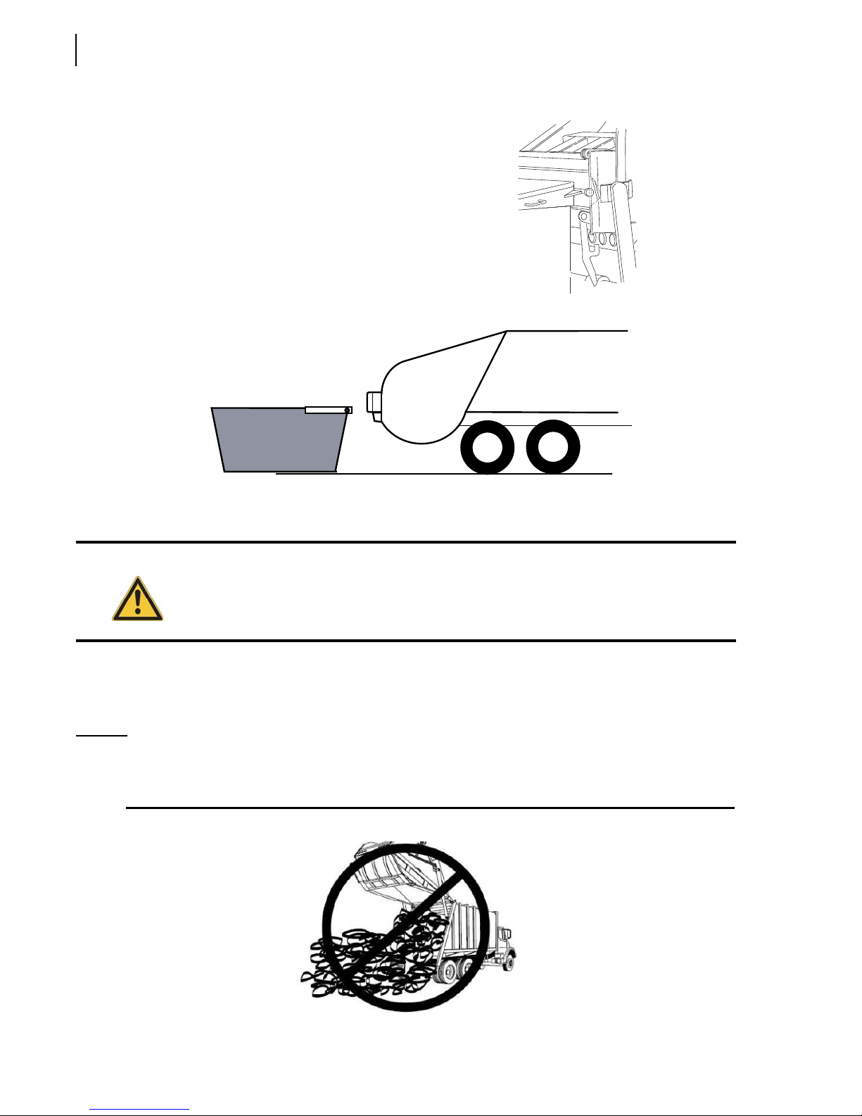
76 Operating the 2R-II™
Once the container is empty, it should be lowered to the
ground, the latch arms released and the cable discon-
nected.
DISCONNECTED
Unloading at Dumpsite
Caution!
1. Apply the brakes, engage the PTO and ensure the transmission is in neutral. Relieve the pressure
on the tailgate by moving the packer panel to the “interrupted cycle position”.
2. Loosen both tailgate clamps and swing them out and forward as far as they will go.
NOTE: On units with a hydraulic locking mechanism, unlock the tailgate first before attempting to
open the tailgate. Use the locking/unlocking controls (see Figure 2-9) on the forward left side
of the body to lock/unlock the tailgate.
Do not unload uphill or against a pile of refuse.
Page 85
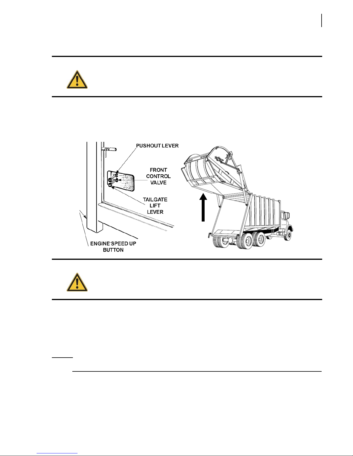
Lifting the Tailgate
Operating the 2R-II™ 77
Danger!
To lift the tailgate:
1. Depress and hold the engine speed-up button.
2. Push the tailgate lift lever rearward and hold until the tailgate is fully raised.
Stand clear when the tailgate is raised! If you need to clean debris from the edges, use a pole
while standing to the side.
Warning!
The TAILGATE OPEN light and backup lights should illuminate. The backup alarm should also
sound.
Ejecting the Load
To eject the load:
1. Depress and hold the engine speed-up button, push the pushout lever rearward and hold until the
pushout panel stops.
NOTE: On units with a telescopic pushout cylinder this will eject the entire load — go on to step 4.
2. Release the speed-up button and pull the pushout lever forward until the pushout cylinder is fully
retracted.
3. Repeat steps 1 and 2 until the pushout panel is as far back as it will go; completely ejecting the
load.
Page 86
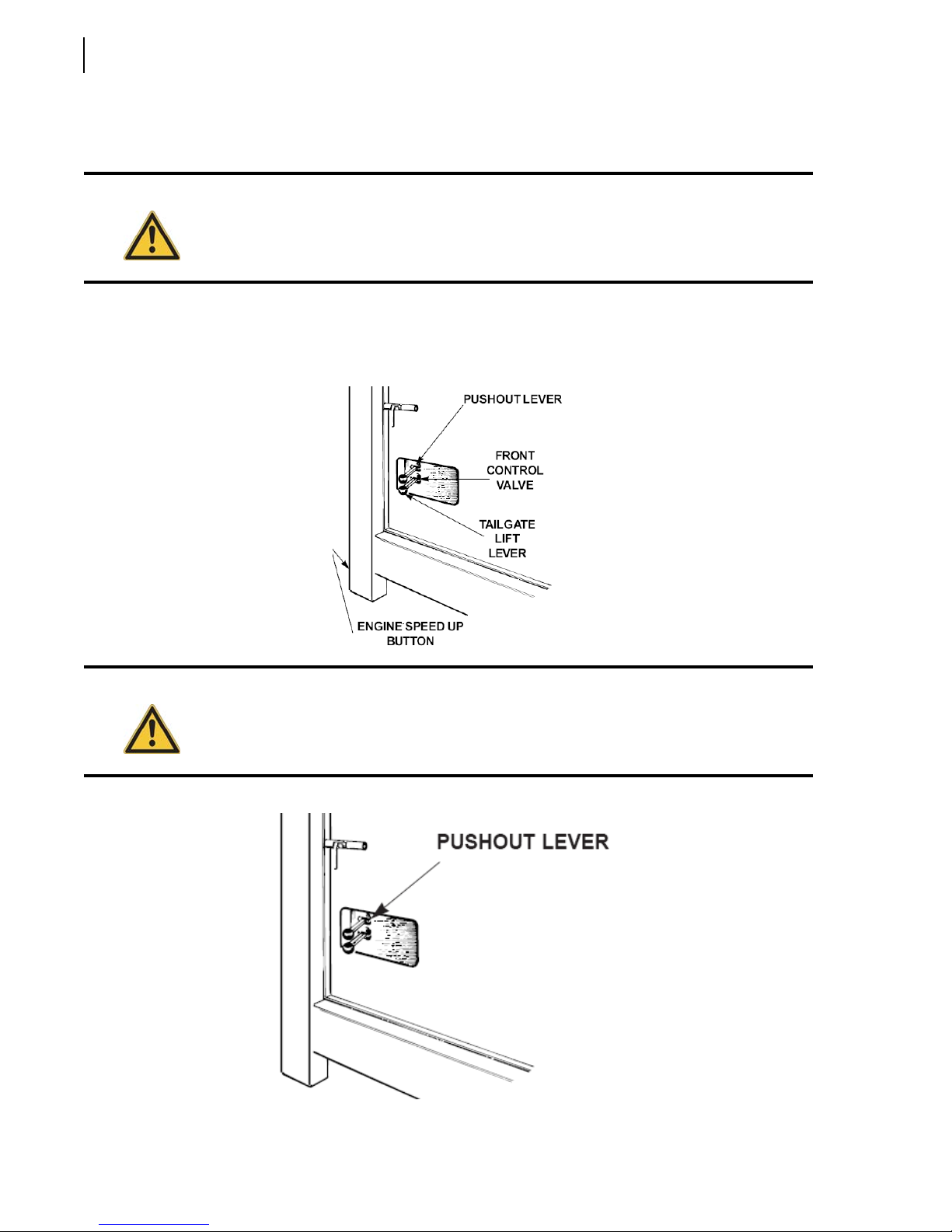
78 Operating the 2R-II™
4. Slowly pull the unit ahead to clear the refuse pile when the tailgate is lowered.
5. Clear debris from the edges with a pole while standing clear off to one side.
Warning!
6. Pull the pushout lever forward to completely retract the pushout cylinder. Now push the pushout
lever rearward extending the pushout cylinder a few inches, thus clamping the bar to the pushout
panel.
Never drive the unit more than 10 feet with the tailgate raised.
Caution!
With the telescopic circuit, the pushout cylinder remains fully extended. If the unit is going to
travel over one mile empty, completely retract the cylinder. When packing is about to resume
extend the cylinder and start packing.
Page 87
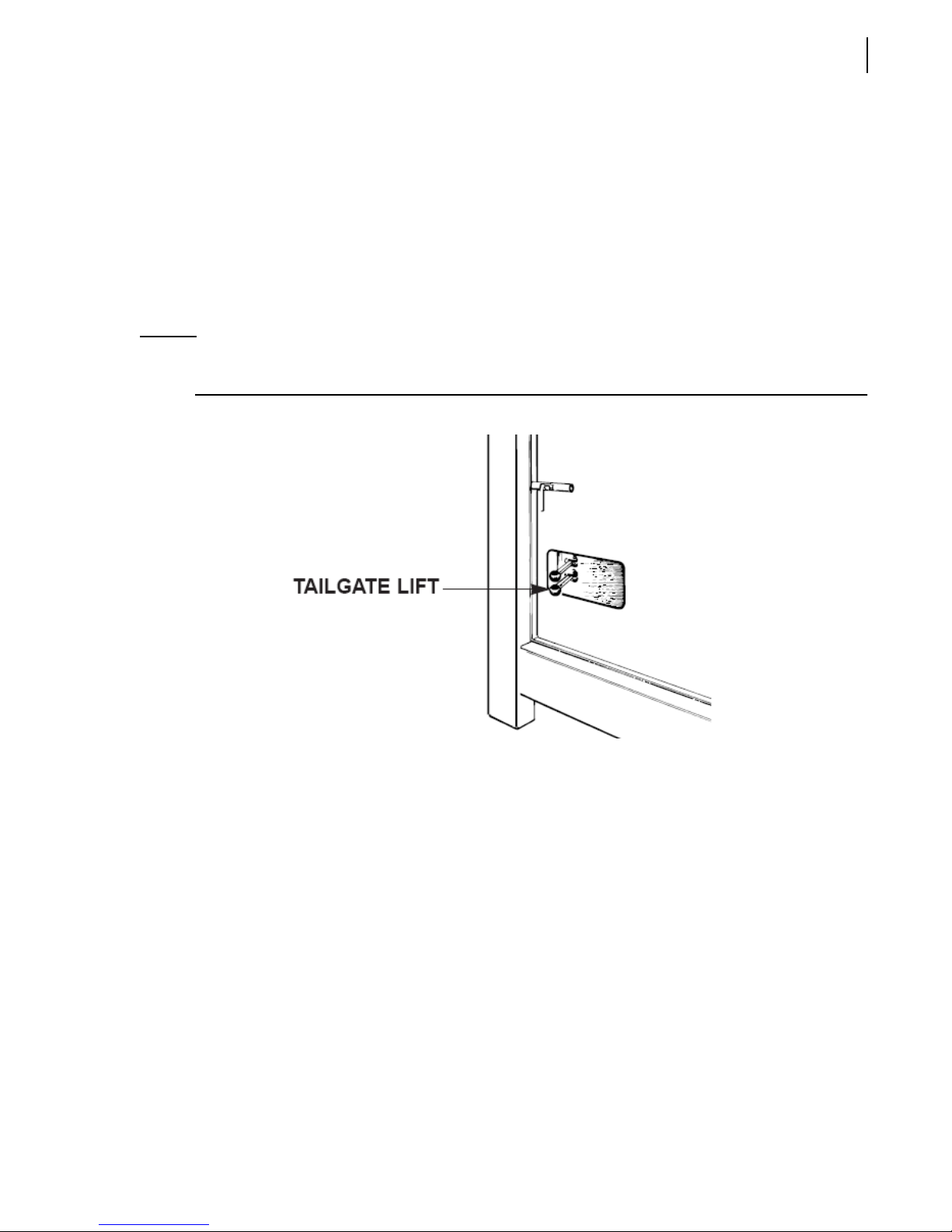
Operating the 2R-II™ 79
Lowering the Tailgate
To lower the tailgate:
1. Pull forward on the tailgate lifting lever slowly and in small increments lower the tailgate a little at
a time.
AVOID SLAMMING SHUT the tailgate.
2. Place the tailgate clamps in the closed position and tighten securely.
On units with a hydraulic locking mechanism, lock the tailgate using the locking/unlocking
controls (see Figure 2-9) on the forward left side of the body.
NOTE: The TAILGATE OPEN light, backup lights and backup alarm should be off once the tailgate is
closed.
Shutting Down the Truck
To shut down the truck:
1. Move the packer panel lever and carrier panel lever to place the packer panel in the “home”
position.
2. Put all controls in neutral.
3. Set parking brake.
4. Turn off the engine speed-up switch.
5. Disengage pump/PTO.
6. Shut off engine.
7. Remove key.
8. Lock truck.
Page 88
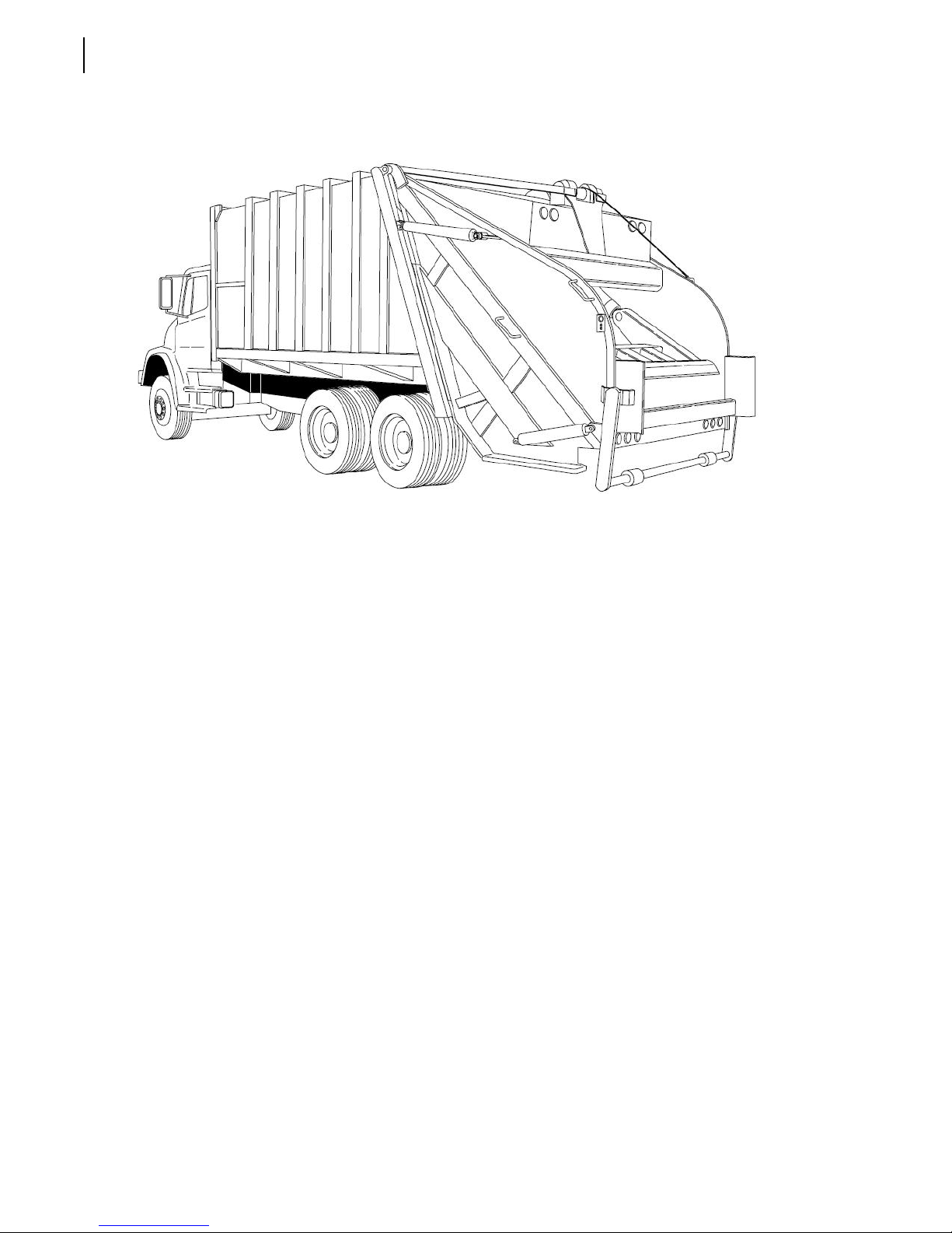
80 Operating the 2R-II™
Page 89

Operating the 2R-II™ 81
Page 90

Our office in the U.S. Our office in Canada
1981 W. Snell Road 175 Route du Pont
Oshkosh, WI 54904 St-Nicolas, QC G7A 2T3
Toll Free: 1-800-231-2771 Toll Free: 1-877-831-8250
Telephone: 1-920-233-2770 Telephone: 1-418-831-8250
General Fax: 1-920-232-2496 Service Fax: 1-418-831-1673
Sales Fax: 1-920-232-2498 Parts Fax: 1-418-831-7561
Mailing Address Mailing Address
P.O. Box 2785 175 Route du Pont
Oshkosh, WI 54903-2785 St-Nicolas, QC G7A 2T3
Parts and Warranty Parts and Warranty
During business hours: During business hours:
7:00 AM to 7:00 PM Central Standard Time 8:00 AM to 5:00 PM Eastern Standard Time
Technical Support Service Technical Support Service
Toll Free: 1-800-231-2771 Toll Free: 1-877-831-8250
(24 hours) (24 hours)
Part# 153139 (rev. 0)
 Loading...