

Page 1
LEAB Automotive GmbH
Thorshammer 6
DE-24866 Busdorf
User manual
Version: 1.6
Issue date: 12.06.2019
MelfBox®
Vehicle electrical input system
User manual
Page 2

Welcome
With the LEAB MelfBox, you have opted for a modern and technically
innovative vehicle electrical input system. Read this manual carefully before
installing and commissioning, and retain it for future reference.
If you have any suggestions or comments about this manual, please let us
know by email: [email protected].
Our website, www.leab.eu, contains further product information as well as
latest versions of the manual. Here you will also find information about
optional accessories or variants of your product.
Table of Contents
1 About this Manual ................................................................................ 1
2 General Safety ...................................................................................... 2
3 Package Contents ................................................................................. 2
4 About the MelfBox ............................................................................... 3
5 Assembly and Installation ..................................................................... 4
5.1 Creating a Body Cutout ................................................................... 4
5.2 Connecting and Assembling the Supply Unit .................................. 5
6 Operation ............................................................................................. 6
7 Cleaning and Maintenance ................................................................... 7
8 Disposal ................................................................................................ 8
9 Technical Specifications ........................................................................ 8
10 Accessories ........................................................................................... 9
11 EU Declaration of Conformity ............................................................... 9
12 Warranty............................................................................................... 9
Page 3
About this Manual User manual
Page 1 of 9
1 About this Manual
The technical data, information and illustrations are carefully compiled and
correspond to the state of the art at the time of printing. LEAB reserves the
right to change products and documentation without prior notice at any
time in accordance with technical requirements and new developments.
Throughout the manual, you will be alerted to warnings and safety notices
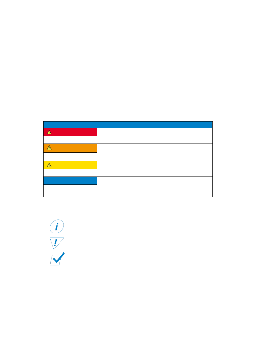
about potential hazards associated with handling the product. The colours
and signal words indicate the severity of the hazard:
Signal word
Meaning
DANGER
Warns of imminent danger resulting in death or
serious injury.
WARNING
Warns of a potentially dangerous situation that
can result in death or serious injury.
CAUTION
Warns of a potentially dangerous situation that
can result in moderate or minor injuries.
NOTICE
Warns of a potentially dangerous situation that
can result in material and environmental
damage.
In this manual you will also find the following symbols:
Shows you useful tips and information about the product.
Indicates a mandatory requirement for the following
instruction.
Shows the result of an instruction.
It is prohibited to copy, duplicate, translate or otherwise pass on the
content of this manual to third parties without the express written
permission of LEAB.
Page 4
General Safety User manual
Page 2 of 9
2 General Safety
This manual supports safe handling of the product. Use the product only in
accordance with its intended use:
The LEAB MelfBox is a vehicle electrical input system.
Assembly and installation should only be carried out by qualified
electricians. Any modifications to the product or its components are
prohibited and do not conform to its intended use. Only use original LEAB
or LEAB-approved accessories.
When installing and using the MelfBox, observe the basic safety
instructions:
Electric current hazard: Before operation, make sure there are no
open or damaged cables.
Replace defective parts or damaged cables immediately.
Only use the MelfBox within the specified voltage limits.
Defect from reverse polarity: Before operation, make sure that all
cables are connected correctly.
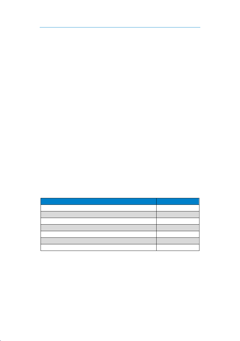
3 Package Contents
Item
No.
Cover
1x
Housing
1x
Housing seal
1x
Body seal
1x
Quick start guide
1x
Screw 3.5 x 14
3x
Cap
1x
Page 5
About the MelfBox User manual
Page 3 of 9
4 About the MelfBox
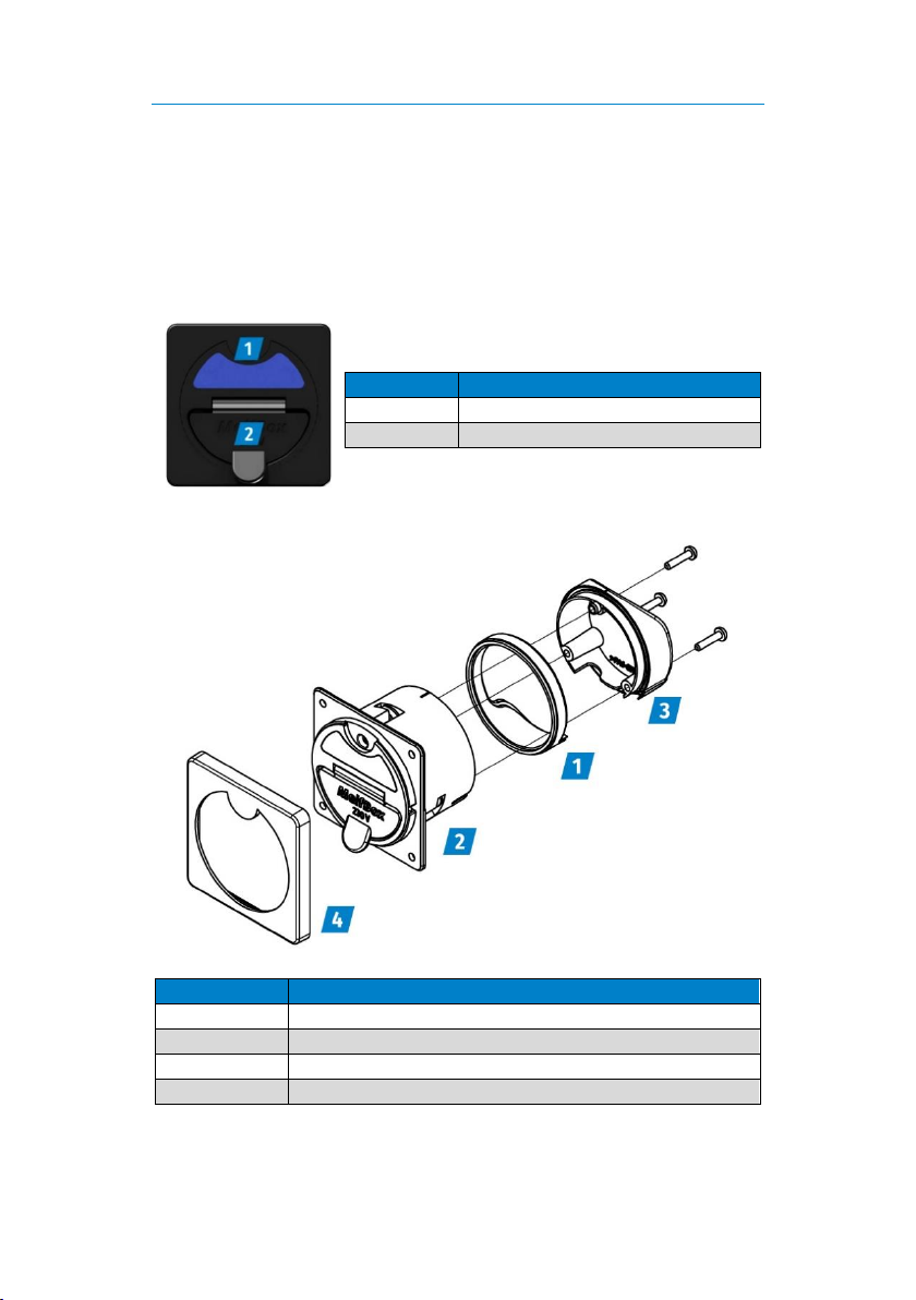
The LEAB MelfBox is a vehicle electrical input system. It has a potential-free
switching contact (normally open contact) to create a start locking
mechanism. An electronic system prevents contact erosion. The status
display provides information about the current system status.
Number
Description
1
Operating display
2
Flap
Number
Description
1
Housing seal
2
Housing with body seal
3
Cap 4 Cover
Page 6
Assembly and Installation User manual
Page 4 of 9
5 Assembly and Installation
Notes on the Assembly Site
To ensure perfect operation, observe the following notes on the assembly
site:
Choose a vertical surface.
Choose a site that has minimum dust and is protected from jet
water.
Make sure that there is sufficient space at the assembly site.
5.1 Creating a Body Cutout
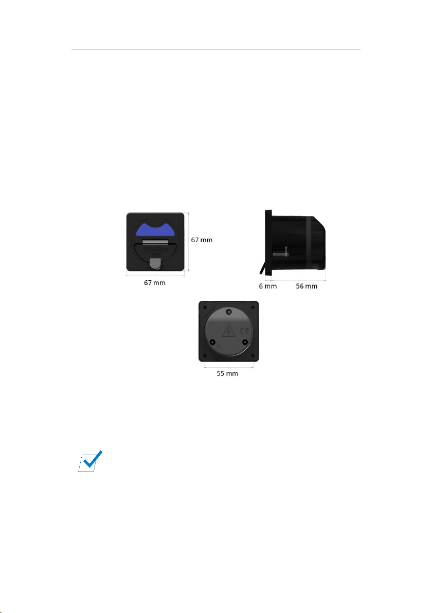
1. Saw a hole (diameter: 55 mm) in the vehicle body.
2. To prevent corrosion, seal the cut surfaces.
The body cutout is created and you can connect the supply
unit.
Page 7
Assembly and Installation User manual
Page 5 of 9
5.2 Connecting and Assembling the Supply Unit
Before connecting the supply unit:
1. Route a connection cable (H07RN-F, 3 x 2.5) in the vehicle.
2. Attach the connection cable to the vehicle installation.
Notice: Install a suitable fuse in the vehicle (up to 16 A).
3. Optional: Route a cable (H05RN-F, 2 x 0.5) for the start-
locking in the vehicle and connect it to the specific vehicle
installation (control module or similar).
Notice: Install a suitable fuse in the vehicle (up to 1 A).
Connecting the Supply Unit
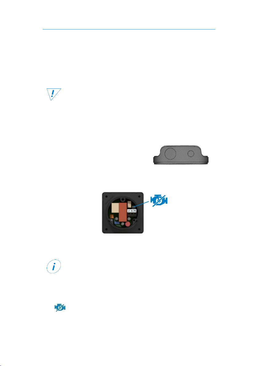
1. Pierce the housing seal at the intended
location with a pointed tool.
2. Feed the connection cable (H07RN-F, 3
x 2.5) through the hole.
3. Connect the wires of the connection cable to the corresponding screw
terminals (see illustration).
Optional: Connecting the start locking mechanism
The MelfBox has a potential-free switching contact (normally
open contact) to create a start locking mechanism.
The design of the start locking mechanism depends on the
vehicle. Inquire from your vehicle manufacturer.
1. Insert the start-locking cable (H05RN-F, 2 x 0.5) through the second
hole of the housing seal (see illustration).
2. Insert the wires of the start-locking cable into the push-in terminals
(max. current: 1 A).
Page 8
Operation User manual
Page 6 of 9
Assembling the Supply Unit
Before assembling the supply unit:
Check the correct connection of the cables in the MelfBox
housing.
Check that the body seal is seated on the housing.
1. Place the housing seal in the cap.
2. Attach the cap to the supply unit with the 3 screws (3.5 x 14).
3. Check the tightness of the housing seal.
4. Push the supply unit into the body cutout.
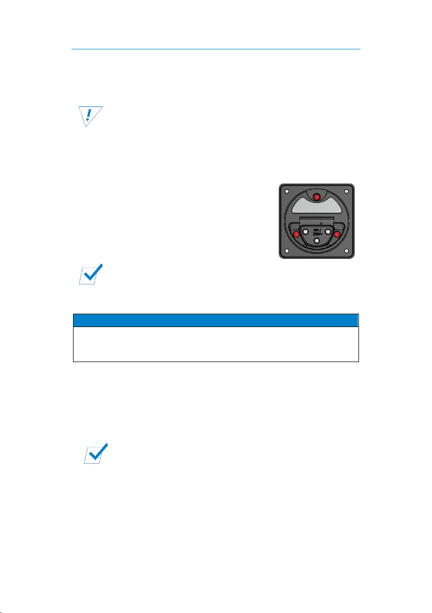
5. Tighten the 3 screws on the front (see
illustration) until the supply unit is firmly
seated in the body cutout (maximum
torque: 1 Nm).
6. Attach the cover.
The MelfBox supply unit is assembled and ready to use.
6 Operation
NOTICE
Defect from inactive start-locking mechanism
Note that start-locking only works when the MelfBox is active
(lit status indicator).
1. Plug the two-pin earthed plug of the connection cable into a 230 V
mains supply.
2. Open the flap of the supply unit.
3. Plug the coupling into the supply unit.
The voltage input is provided at the load output of the supply
unit. Connected consumers are supplied. The status display
shows the operating status of the MelfBox.
Page 9
Cleaning and Maintenance User manual
Page 7 of 9
Operating Status Overview
Operating
display
Operating status
Blue, flashing
The MelfBox is active.
A minimum of 50 W power is removed from the supply
unit (the greater the power, the faster the flashing).
Yellow,
steady light
Note: This operating condition only occurs immediately
after inserting the MelfBox coupling. The MelfBox does
not switch back from "blue" to "yellow".
The MelfBox is active.
No power is removed.
Check the connection of the consumers.
Check the fuse at the outlet of the MelfBox.
7 Cleaning and Maintenance
WARNING
Injury from electric shock
Before doing any work, make sure that the MelfBox system is
de-energised.
NOTICE
Strong jet water can cause damage
Do not aim the pressure washer or other devices directly at
the MelfBox supply unit.
Regular Activities
Check the MelfBox for external damage each time before you use
it.
Clean the supply unit once a month with compressed air.
Protect the coupling and cable from being run over, getting wet
and other liquids.
Regularly check the tightness of the supply unit in the vehicle
body.
Page 10
Disposal User manual
Page 8 of 9
8 Disposal
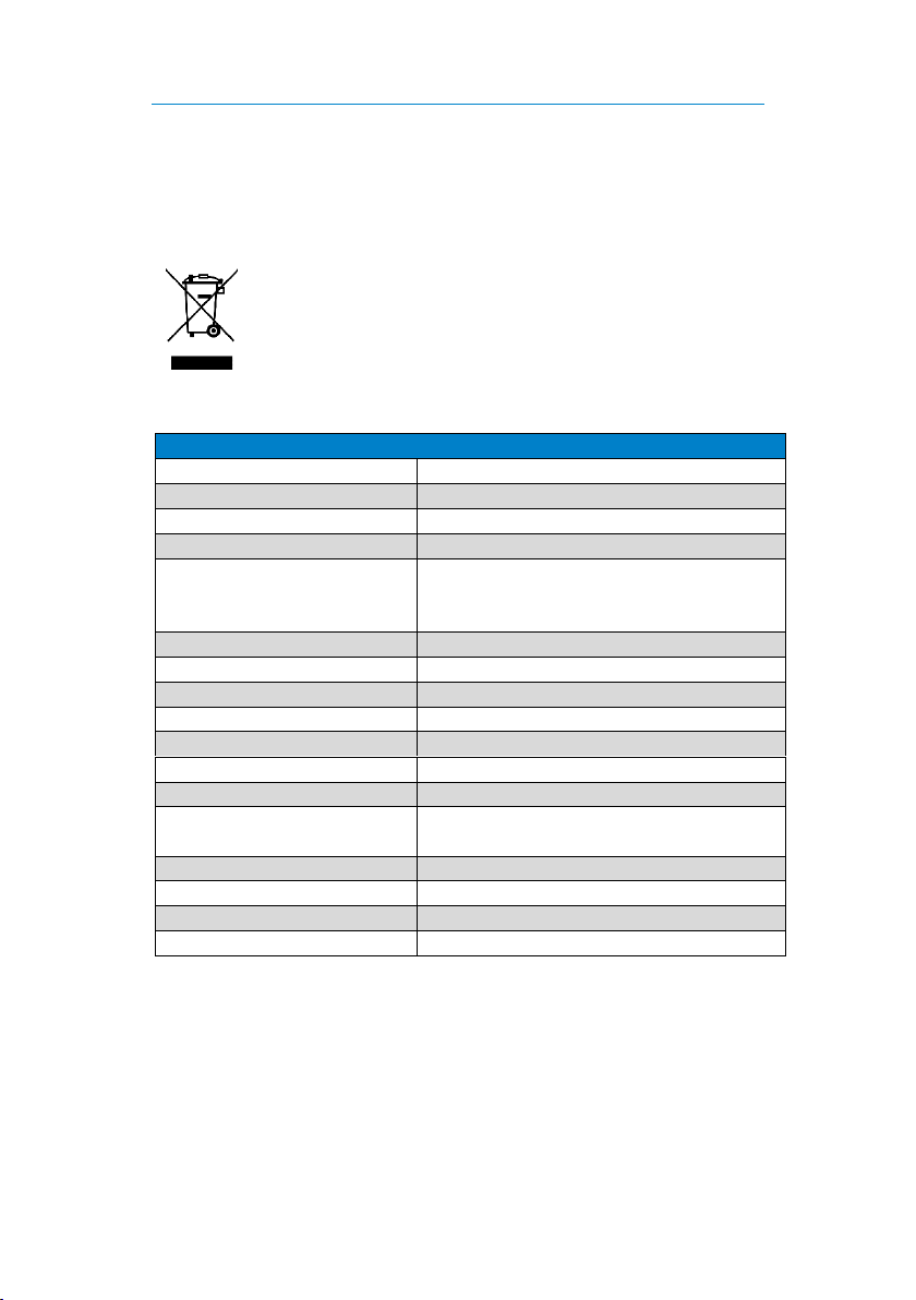
Dispose of the product in accordance with the Waste Electrical and
Electronic Equipment Regulations (WEEE).
The product must not be disposed of with household waste.
Take it to a recycling point or send it to your point of sale.
9 Technical Specifications
MelfBox, Supply Unit
Part number
1105002001
Nominal voltage (AC)
230 V (+/- 10 %)
Current, max. (AC)
16 A
Frequency
50 Hz
Potential-free switching
contact (normally open
contact)
1 A
Operating display
LED
Installation diameter
55 mm
Installation depth
56 mm
Length
62 mm
Width
67 mm
Height
67 mm
Cable cross-section
2.5 mm²
Material
Polyamide, glass fibre reinforced (PA6
GF30)
Contacts
L1 / N / PE
IP rating
IP55
Protection class
I
Weight
0.12 kg
Page 11
Accessories User manual
Page 9 of 9
10 Accessories
You can order accessories either through your dealer or directly from LEAB.
Just visit our webshop at www.leab.eu or call us on: +49(0) 4621 9 78 60-
110.
Part number
Description
1105001001
Connection cable, 2.5 m
1105001002
Connection cable, 5 m
1105001003
Connection cable, 10 m
11 EU Declaration of Conformity
The MelfBox
complies with the requirements of the following
directives:
2014/35/EU: NRL
2014/30/EU: EMC
2011/65/EU: RoHs
The current and complete document is available on request from
12 Warranty
LEAB grants a legal guarantee from the date of purchase if the installation
of the product has been carried out by a specialist and if it has been used in
accordance with the intended use.
Requirements for the completion of work under warranty are:
Invoice or delivery note
Model name or type
Detailed description of the fault and the installation
Procedure
If the product does not operate correctly following the instructions in this
manual, or if the error persists, contact your dealer or LEAB.
Page 12

LEAB Automotive GmbH
Thorshammer 6
DE-24866 Busdorf
Germany
Tel.: +49(0) 4621 9 78 60-0
Fax: +49(0) 4621 9 78 60-260
Email: [email protected]
Web: www.leab.eu
 Loading...