

Page 1
REV.
MPD
4/6/11
4/6/11
4/6/11
JRA
DLR
MPD
A
DOCUMENT RELEASE
DESCRIPTION
REVISIONS
ECN
DD2922
DATE
3/8/2011
APPROVED
LS Plus 300
ALL DIMENSIONS IN INCHES
UNLESS OTHERWISE SPECIFIED.
TOLERANCES:
FRACTIONS=±
ANGLES=±
MATERIAL
NOTED
.
THIRD-ANGLE PROJECTION
.
.XX=±
.
°
.XXX=±
DRAWN
DAW
CHECKED
ENG APPD
.
.
PROJ APPD
PROJECT NO.
NOTICE: THE INFORMATION AND
DESIGN IN THIS DOCUMENT IS THE
PROPERTY OF LEA INTERNATIONAL.
ALL RIGHTS RESERVED.
DATE
3/8/11
.
.
.
.
.
.
DD2922
TITLE
SIZE
A
SCALE
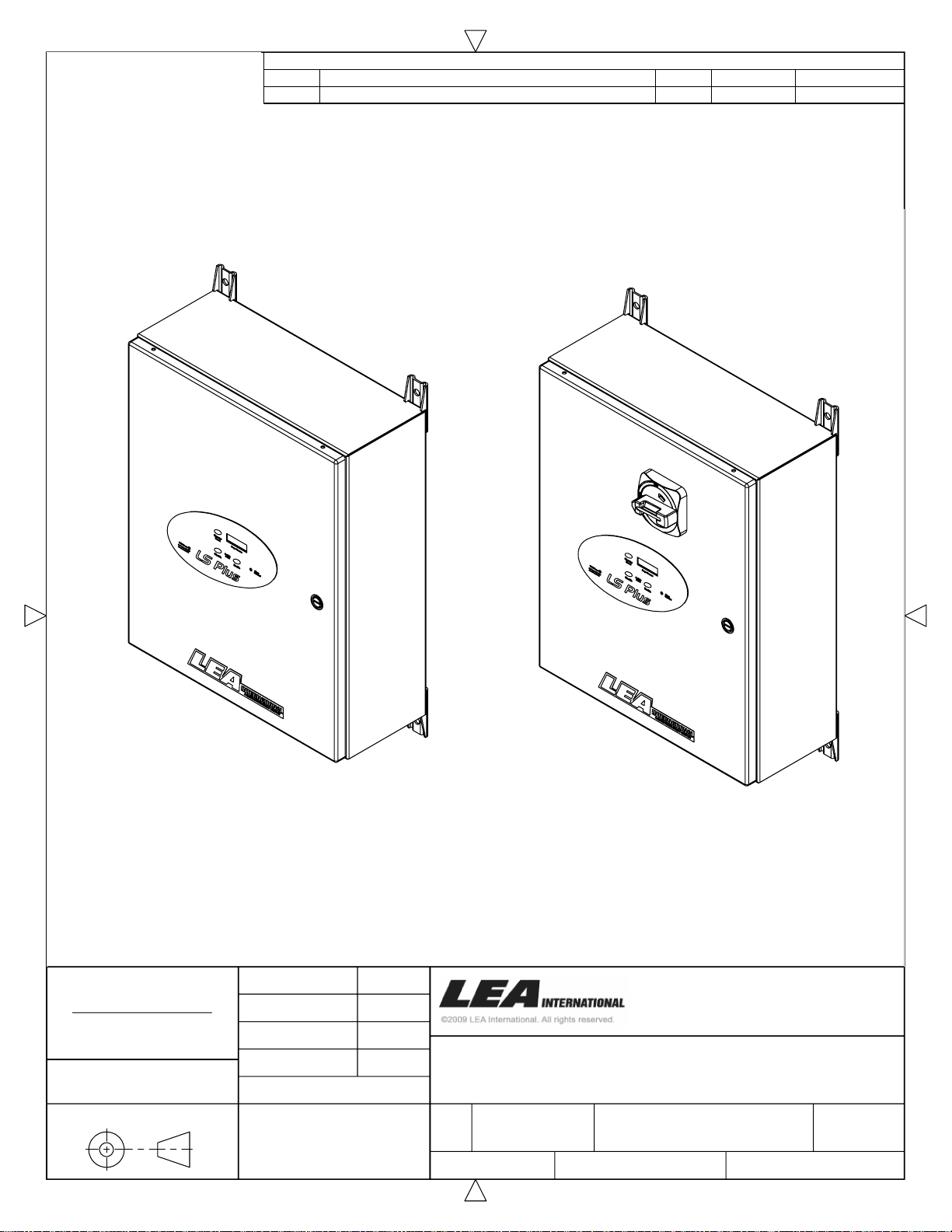
LS Plus 300 with
Disconnect Switch
10701 Airport Drive, Hayden, ID 83835, USA
.
+1.208.772.8515 FAX +1.208.762.6117
.
800.882.9110 www.protectiongroup.com
INSTALLATION MANUAL
LS PLUS 300 AC PROTECTOR
1
REV
12
CAGE
30992
1:8
DRAWING NUMBER
B39-38-0003
PRODUCT CATEGORY
ACL
PAGE OF
A
Page 2
2
Page 3
Pre-Install Notes
READ ALL WARNINGS BEFORE ANY SERVICE OR TESTING
Do not install, make any adjustments, or replace any components inside the
enclosure with the power supply turned on. Under certain circumstances, dangerous
potentials may exist even when the power supply is off. To avoid casualties, always
turn the main power supply off before performing maintenance and/or testing.
HAZARD OF ELECTRIC SHOCK, BURN, OR EXPLOSION
CAUTION
The installation of a surge protection device (SPD) must be done by qualified
electrical personnel. A SPD must be grounded through the power system ground for
proper operation.
WARNING
Before installing the suppressor, AC power must be OFF. Failure to do so could
result in damage to the suppressor and poses a potential electrical shock hazard to
personnel.
is off.
Read SPD label on side of the enclosure to verify voltage configuration.
Discontinue installation if the measured voltage is not in the range of the model
voltage configuration of the SPD being installed. Contact LEA International technical
support with any questions concerning the voltage configuration prior to installation
and application of power.
Perform such work only after reading and understanding all of the instructions
contained in this manual.
Beware of potential hazards, wear personal protective equipment and take
adequate safety precautions.
Before performing visual inspections, tests, or maintenance on the equipment,
disconnect all sources of electric power. Assume that all circuits are live until they
have been completely de-energized, tested, grounded, and tagged. Pay particular
attention to the design of the power system. Consider all sources of power, including
Always use a properly rated voltage sensing device to confirm that power
Handle this equipment carefully and install, operate and maintain it correctly in order
for it to function properly. Neglecting fundamental installation and maintenance
requirements may lead to personal injury, as well as damage to electrical equipment
or other property.
Carefully inspect your work area and remove any tools and objects left on /or in the
enclosure.
Replace all devices and covers before turning on the power to this equipment. All
instructions in this manual are written with the assumption that the customer has
taken these measures before performing installation or testing.
Failure to follow these instructions could result in DEATH or
serious injury.
3
Page 4

Installation Procedure
Notes
Please read the entire installation manual before installing this SPD. Carefully
unpack the SPD, removing all packaging material. Inspect for any signs of damage
that may have occurred during shipment. If any damage is found, stop installation
and contact LEA International.
The SPD should only be installed by a licensed electrician.
All local and National Electric Codes must be observed.
Verify the voltage configuration on the SPD label matches the actual system voltage
configuration of service point.
For optimal SPD performance, verify that earth ground resistance is less than 25
ohms (per NEC).
Before installation, shut off power to prevent accidental electrical shock or injury.
Make sure all conductors are sized appropriately for this SPD.
Mounting
The SPD should be mounted as close as possible to the connection of service point.
The SPD is mounted using the four mounting holes located near the enclosure
corners.
Electrical conductors should enter the top of the SPD enclosure, or on either side
near the top of SPD enclosure.
Electrical conduit should be of sufficient size per NFPA 70 and National Electrical
Code. For optimum SPD performance, conduit with no sharp bends.
Conductor Size
Terminal Block
The lugs accept phase and Neutral conductors #8 to #1/0 AWG,
the Neutral and Safety Ground accept #8 to #1/0 AWG.
All conductors recommended to be insulated stranded copper greater than #6
AWG diameter.
Disconnect
The disconnect switch lugs accept phase conductors #10 to # 4 AWG,
the Neutral and Safety Ground accept #8 to #1/0 AWG.
All conductors recommended to be insulated stranded copper greater than #6
AWG diameter.
.
4
Page 5

AC Power Connection
The SPD is installed in parallel with the incoming phase conductors.
It is recommended to connect the SPD to a 60A circuit breaker. This allows for
servicing of the SPD without shutting power off at the panel main breaker.
Route all SPD conductors taking care to avoiding sharp bends and keeping all leads
as short as possible.
To ensure optimum SPD performance, verify that all electrical connections are clean.
Connect the phase and neutral wires to the terminals marked Phase 1, Phase 2,
Phase 3, and Neutral.
Connect the green safety ground wire (building ground system) to the Safety Ground
lug.
Tighten all connections to the recommended torque value.
Remote Alarm Connection
The SPD offers one set of dry contacts for remote alarm monitoring. These screw
terminal connections are located on the PC board as shown on Pages 8 or 10. The
three connections are labeled NC (Normally Closed), NO (Normally Open) and C
(Common).
Remote Alarm Contact Maximum Ratings:
125 Vdc / 0.24 A
125 Vac / 0.5 A
30 Vdc / 2.0 A
Final Check
Apply AC power to the SPD.
The SPD
If the
technical support at 800.882.9110.
If the
the audible alarm. The
TVSS Status
TVSS Status
Alarm Disabled
LED is red or not illuminated, contact LEA International’s
LED should be illuminated green.
LED is red, press the audible alarm
Alarm Disabled
LED will turn dark
Enable
button to
Enable
5
Page 6

Troubleshooting
The SPD operational status can be seen on the front door of the enclosure. There is
no need to open the unit for any reason.
TVSS Status LED
A green LED indicates power is applied and all SPD protection modes are normal.
A red LED indicates the SPD needs servicing.
Surge Counter
Surge Counter Display
The LCD display indicates there was an event and has recorded the number of
surge/transients events since the counter has been reset.
If the surge counter display is blank, the battery may be defective or dead. Please
contact LEA Technical support.
Counter Reset button
Press to reset the surge counter to zero.
Audible Alarm
Alarm Disabled LED
A dark LED indicates the audible alarm circuit is enabled.
A red LED indicates the Audible Alarm has been silenced and serves as a reminder
that the SPD needs to be serviced.
Audible Alarm Disable button
Press to turn off the audible alarm. The
Alarm Disabled LED
will turn red and
serves as a reminder that the SPD needs to be serviced. If the SPD has been
severely damaged disconnect power to the SPD using the circuit breaker or
disconnect switch to silence the alarm.
Maintenance of electrical devices should be done only by trained professional
electrician.
Audible Alarm Enable button
Press the Enable button for the audible alarm. The
Alarm Disabled LED
will turn
dark
Maintenance
The SPD should be scheduled for periodic inspection to ensure the SPD is
operational and all wire connections are tight.
If the SPD needs replacement, please contact LEA International for replacement at
800.882.9110 or online at www.protectiongroup.com.
.
6
Page 7
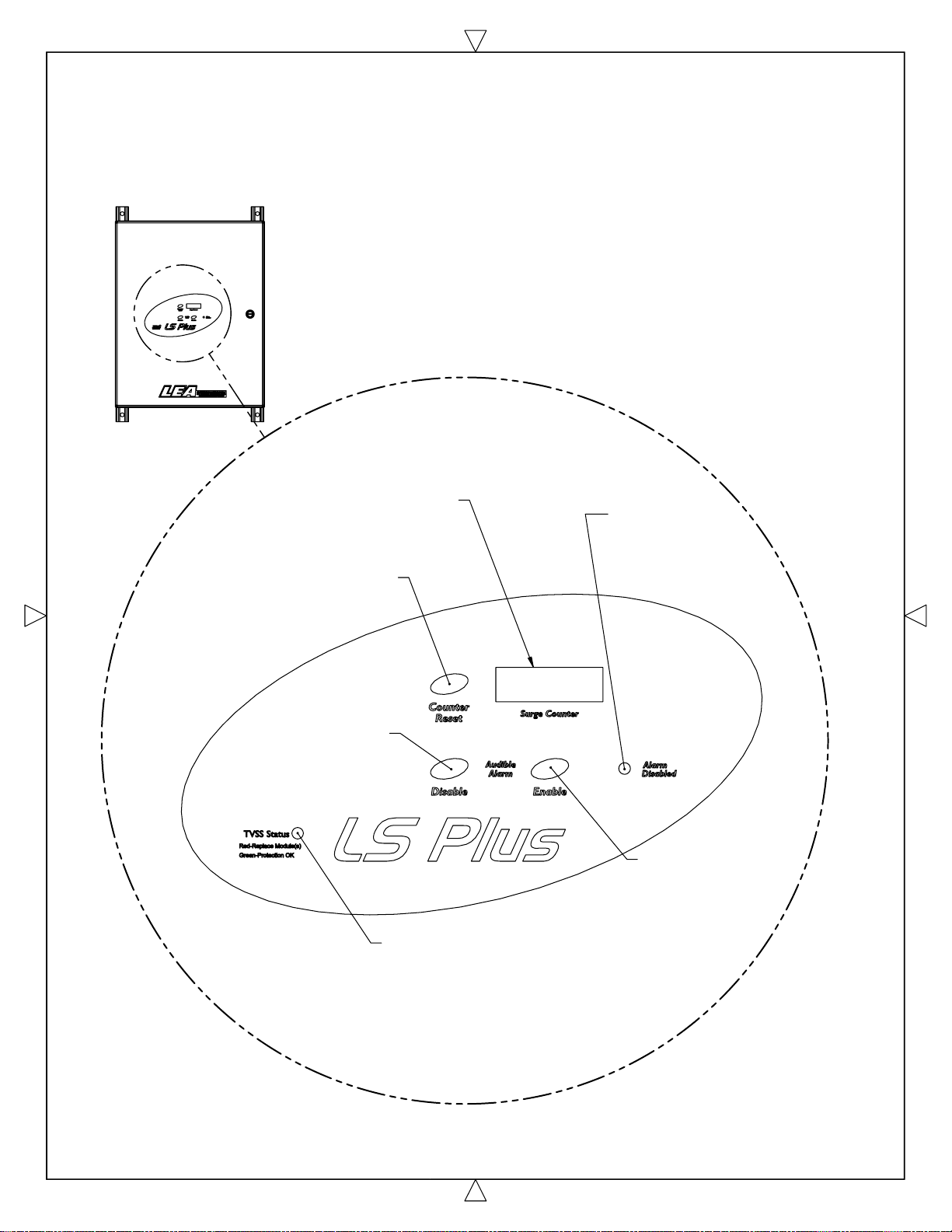
Please Note:
LS Plus 300 shown without the Disconnect Switch.
The Operation of the Surge Counter and
Audible Alarm Switch is same for
both models.
Surge Counter
Records any
Suppressed Transients
Counter Reset
Press to reset
Surge Counter to zero
Alarm Disabled
A Red Illuminated
Light Indicates
Audible Alarm
is Disabled
1
Audible Alarm
Disable
Turns OFF the Alarm
and Illuminates the
Alarm Disable Light
.
Button
TVSS Status Indicator
Light Illuminated Green Indicates
Normal Operation with All
Protection Modes Functioning
Light Illuminated Red Indicates
SPD Needs Replacement
Audible Alarm
Enable
Enables the
Alarm and Turns
OFF the Alarm
Disabled Light
Button
7
Page 8
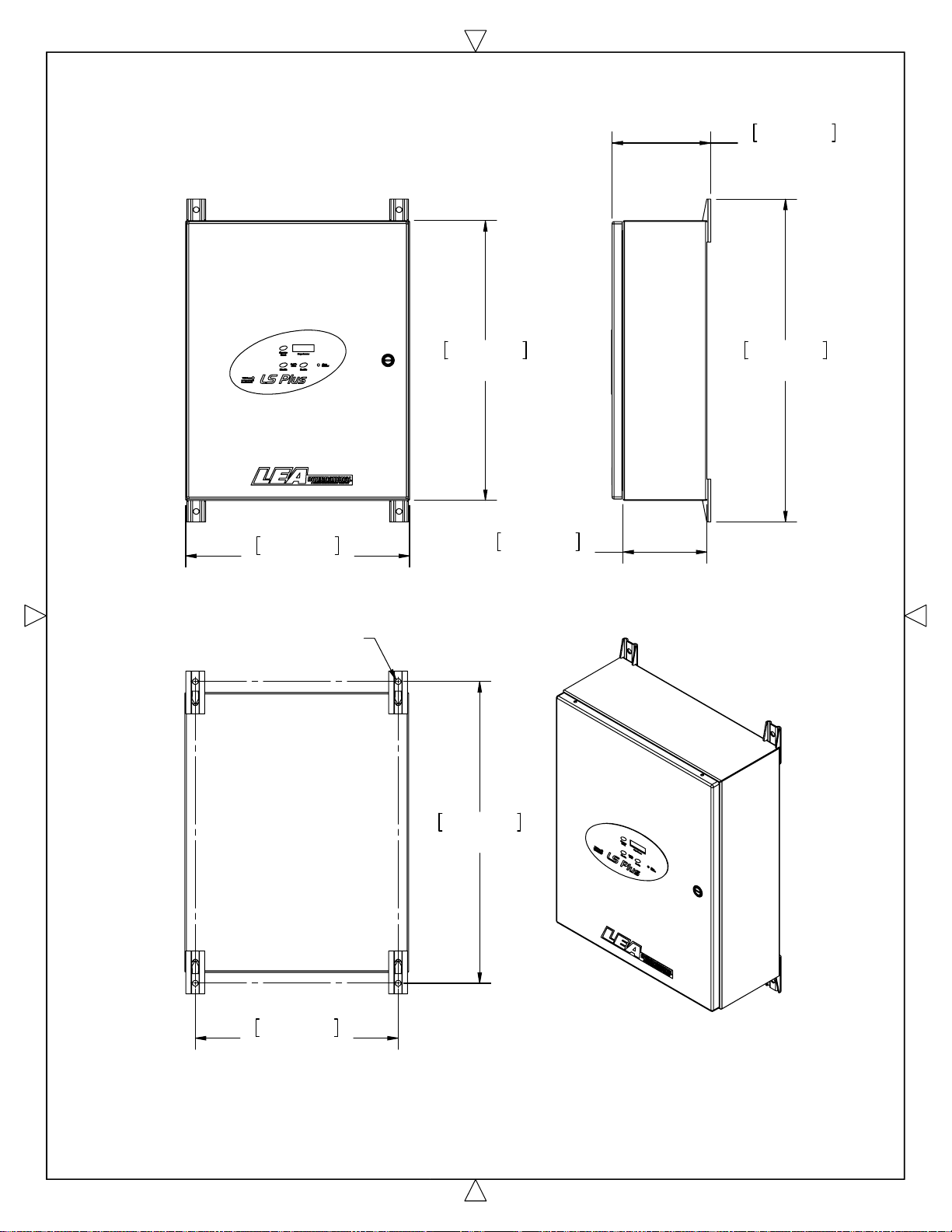
179 mm
7-1/16"
406 mm
16"
Use 3/8" [ 10 mm ]
Mounting Hardware
508 mm
20"
152 mm
586 mm
23-1/16"
6"
Mounting:
External mounting brackets with 0.41" [ 10.3 mm ] mounting holes.
Dimensions:
Weight:
42 lbs / 19 kg
548 mm
21-9/16"
368 mm
14-1/2"
Mechanical Specifications for LS Plus 300
[ Dimensions for Reference Only ]
20" X 16" X 6" [ 508 mm X 406 mm X 152 mm ]
8
Page 9
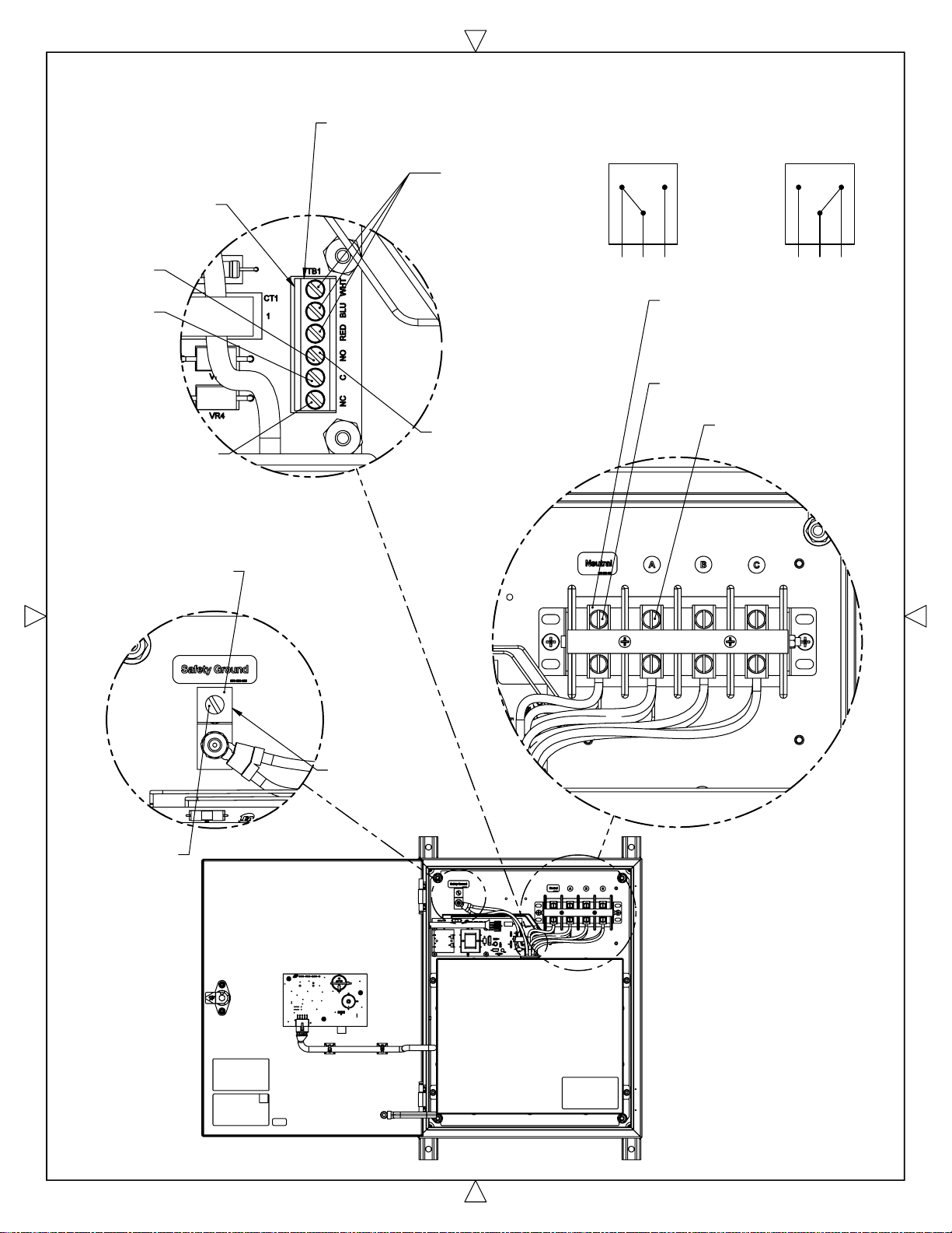
Note:
Remote Alarm Contacts
Change State with Loss
of Power
Remote Alarm
Contacts
Normally
Open
Common
Normally Closed
Contact is Closed
when SPD is Powered
and Functional
[ Normal State ]
Wire Range
#24 to #14 AWG
PLEASE NOTE:
Alarm Wires from
SPD are hidden to
show proper
placement of
Wires for the
Remote Alarm
Contacts
3X Torque
Specification
4.5 in-lbs
[ 0.5Nm ]
Remote Alarm
Contacts
NC
Contact Closed
with SPD powered
and Functional
[ Normal State ]
Remote Alarm
Contacts
NO
Contact Open
with Power OFF
or SPD Requires
Replacement
NC C NO NC C NO
4X Wire Strip Lengths
for Phase & Neutral
Connections
0.5" [ 13 mm ]
4X Torque Specification
50 in-lbs [ 5.6 Nm ]
Wire Range
#8 to #1/0 AWG
Wire Strip Length
0.5" [ 13 mm ]
Lug Torque
Specification
50 in-lbs
[ 5.6 Nm ]
Wire Range
#8 to #1/0 AWG
9
Page 10
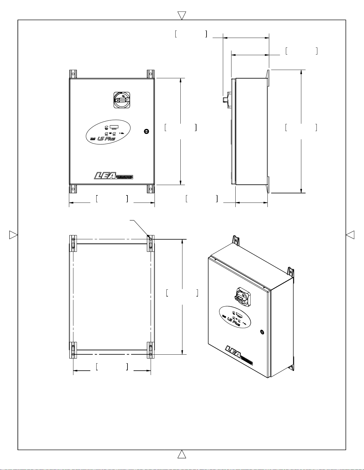
218 mm
8-5/8"
179 mm
7-1/16"
406 mm
16"
Use 3/8" [ 10 mm ]
Mounting Hardware
508 mm
20"
152 mm
548 mm
21-9/16"
585 mm
23-1/16"
6"
Mounting:
Dimensions:
Weight:
External mounting brackets with 0.41" [ 10.3 mm ] mounting holes.
43 lbs / 19.5 kg
368 mm
14-1/2"
Mechanical Specifications for LS Plus 300
with Disconnect Switch
[ Dimensions are for Reference Only ]
20" X 16" X 6" [ 508 mm X 406 mm X 152 mm)
10
Page 11
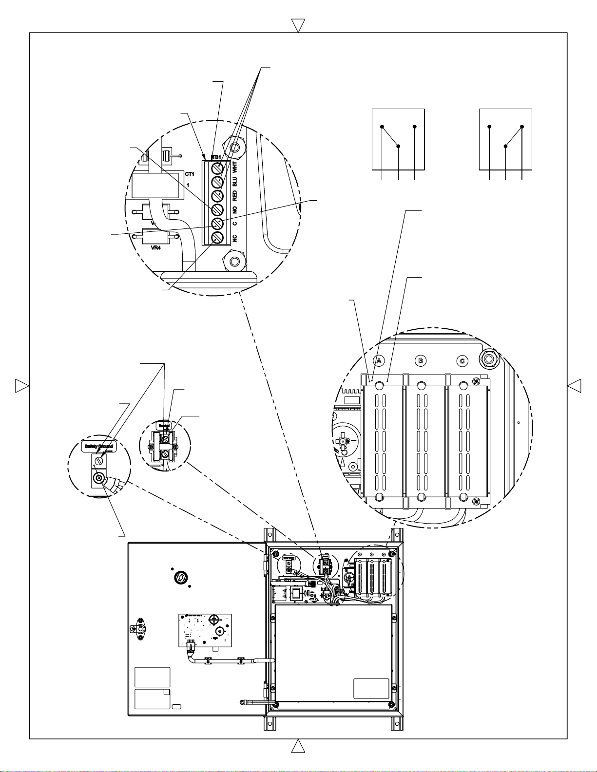
Note:
Remote Alarm Contacts
Change State with Loss
of Power
Wire Range
#24 to #14 AWG
Remote Alarm Contacts
Normally Open
Common
Normally Closed
Contact is Closed
when SPD is
Powered and Functional
[ Normal State ]
PLEASE NOTE:
Alarm Wires from
SPD are hidden to
show proper
placement of
Wires for the
Remote Alarm
Contacts
3X Torque
Specification
4.5 in-lbs
[ 0.5 Nm ]
Wire
Range
#10 to #4 AWG
Remote Alarm
Contacts
NC
Contact Closed
with SPD powered
and Functional
[ Normal State ]
Remote Alarm
Contacts
NO
Contact Open
with Power OFF
or SPD Requires
Replacement
NC C NO NC C NO
3X Wire Strip Lengths
for Phase Connections
into the Disconnect
Switch
0.5" [ 13 mm ]
3X Torque Specification
for Disconnect Switch
25 in-lbs [ 2.8 Nm ]
Torque
Specification
50 in-lbs [ 5.6 Nm ]
Wire Range
#8 to #1/0 AWG
Ground
Lug
Strip
Length
0.5" [ 13 mm ]
Wire Range
#8 to #1/0 AWG
Wire Strip
Length
Neutral
Block
0.7" [ 17.4 mm ]
11
Page 12
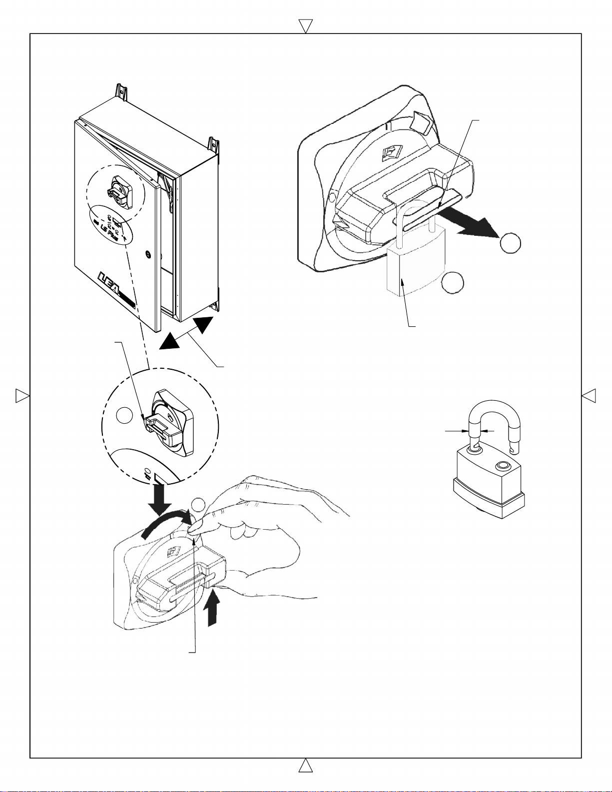
Lock Out of Enclosure in the OFF Position
if Required
Step 1
Turn Handle
to the OFF
Position
ON
Pull Out
Locking Tab
to Install
Locking Device
O
F
F
1
2
Install Lock
Disconnect Handle must
be in the OFF Position
to Open or Close
the Enclosure Door
1
3/16"-5/16"
[ 5-8 mm ]
ON
O
F
F
Step 2
Press Release as
Shown to Release
Disconnect Handle
from the Disconnect
Switch to Open
or Close the
Enclosure Door
2
Handle Locking Tab only
accepts a Shackle
Diameter as shown.
(Lock not supplied by LEA)
Disconnect Handle Operation
12
 Loading...