

LDT Littfinski Daten Technik RM-GB-8-N-F Operation Instruction
Littfinski DatenTechnik (LDT)
Operating Instruction
Feedback Module
with integrated
8-fold track occupancy detectors
for the s88-feedback bus
from the Digital-Professional-Series !
RM-GB-8-N-F Part-No.: 320102
>> finished module <<
⇒ controls up to 8 different tracks
(current detection from 0,001[1mA] up to 3 ampere).
⇒ integrated voltage control
(avoiding “track free” feedback in case of power failures).
⇒ separated by opto isolation
(between track and feedback bus).
⇒ for s88 standard connections and s88-N
(with 6-poles s88-pinbars and RJ-45 sockets].
⇒ suitable for following digital systems:
Märklin Digital~/=, Central Station 1 and 2, Intellibox, TWIN-
This product is not a toy! Not suitable for children under 14 years of age! The kit
contains small parts, which should be kept away from children under 3! Improper
use will imply danger of injuring due to sharp edges and tips! Please store this
instruction carefully.
CENTER, HSI-88 (-USB), EasyControl, ECoS, DiCoStation.
CE Part-No.:
1370370
Introduction / Safety Information:
You have purchased the 8-fold feedback module RM-GB-8-N
with integrated detection of track occupancy for your model
railway. The RM-GB-8-N is a high quality product that is
supplied within the Digital-Professional-Series of
Littfinski DatenTechnik (LDT).
We wish you having a good time using this product.
The finished module comes with 24 month warranty.
• Please read the following instructions carefully. Warranty will
• Attention: Please switch off your digital control unit and
General functional description:
The RM-GB-8-N feedback module combines the occupied
track detection and the feedback report function. The 8
detectors for occupied tracks work by detection of current.
In cases a connected track is occupied by an object with a
minimum of 0,001 Ampere (1mA) consuming current, the
track will be detected as occupied.
Locomotive decoder, coach lights or axles with electrical
resistance are consumer of electrical power and therefore
induce the detection of an occupied track.
The maximum DC current on the tracks can be up to 3
Ampere per output. A peak current of 7 Ampere will be
possible at short term . Then has the booster to identified the
overload or the short circuit and has to cut-off the current .
Multi-Digital
expire due to damages caused by disregarding the operating
instructions. LDT will also be not liable for any consequential
damages caused by improper use or installation.
unplug all transformers from AC-current before starting
to assemble the unit.
s88-N
s88-N
OUT
s88-N
IN
The track voltage and the feedback bus are separated by
opto-galvanic. The current for the tracks can therefore safely
be supplied from different transformers without having a
negative effect on the digital control units.
The modular concept of occupied track detectors and
feedback decoders implements a considerable galvanical
problem: as soon as there is no electrical power on the tracks,
all tracks are detected as free because no consuming current
is detected. There are track occupied detectors available on
the market which use an auxiliary voltage to solve this
problem, but this can influence sometimes the locomotive
decoder causing disturbances and is therefore no suitable
solution.
As the feedback module RM-GB-8-N has a build-in intelligence
(microprocessor Z86... [IC1], we have integrated a solution
called voltage monitor. In case of voltage drop or short circuit
there is no inaccurate “free track” detection and report back via
the feedback bus to the digital control unit or the PC. All track
occupancies will be “frozen“ during this phase of voltage
interruption.
As soon as there is current on the tracks again the actual
situations on the tracks will be detected and reported back via
the feedback bus.
The RM-GB-8-N feedback module is suitable for a
decentralize installation underneath of the model railway
installation. There are 4-bores on the edges of the modules for
quick and easy installation. Suitable assembly parts (plastic
distance spacers and wood screws) are available under the
order code MON-SET.
Connecting the RM-GB-8-N to Digital
Central Units respectively Interfaces:
On Märklin INTERFACE, Central Station 1 and 2, Intellibox,
TWIN-CENTER, EasyControl, ECoS, HSI-88-(USB) and
DiCoStation can be the occupation reports of up to 62
RM-GB-8-N evaluated.
Up to 6 feedback modules RM-GB-8-N can be connected to
each Märklin MEMORY.
Electrical power will be supplied from the s88-feedback bus
to all feedback modules. This will apply for the s88-standard
feedback modules and as well as for the feedback modules
RM-GB-8-N. The power consumption of the standard feedback
modules is considerable low. The RM-GB-8-N requires 0,003
Ampere (3mA) only.
The s88 feedback bus of digital central units and interfaces
Standard track
can mostly supply a maximum load of up to 0,5 Amp. If the
maximum quantity of 62 feedback modules RM-GB-8-N are
connected, the bus has to supply 62 x 0,003A = 0,186A.
If you want to extend your model railway layout with RM-GB-8-
N feedback modules you can easily combine those with our
feedback modules RM-DEC-88(-Opto) and RM-88-N(-Opto)
or s88 feedback modules of other manufacturers.
The address of the feedback modules is related to the
sequence of the connection to the digital central unit or to
the interface. The feedback module which is directly
connected to the central unit will get always the address 1.
Further details are available within the operation instructions
of your digital central unit or the interface.
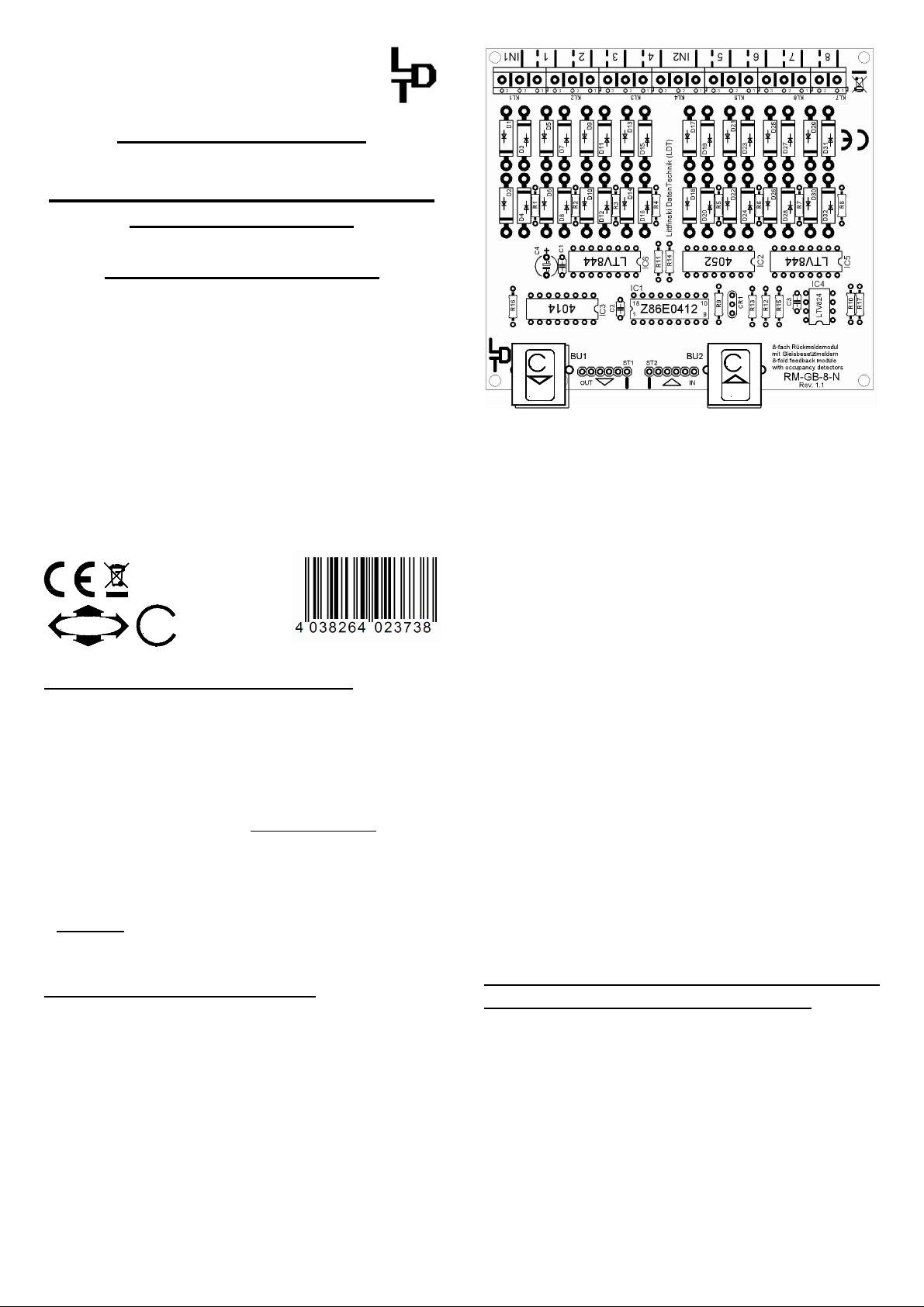
The RM-GB-8-N contains two 6-poles pin bars for the s88-
standard connection and two RJ-45 sockets for a bus
connection in accordance to
s88-N
.
At the RM-GB-8-N are the pin bars and sockets marked with
OUT and IN.
OUT is the connection in direction of the digital central
unit or interface. IN shall be connected to the next following
feedback module within the s88 bus line.
Digital central units and interfaces contain always a s88input for a s88-standard connection.
We supply an interference protected twisted s88-bus-cable
with original s88-bus plugs for the s88-standard
connection.
The plugs of the s88-bus-cable are correct assembled on
the 6-poles pin bar of the RM-GB-8-N when the position of
the white single wire corresponds to the white marking on
the pc-board next to the pin bar. The cable shall lead directly
away from the feedback module. Additionally attend to the
correct position of plug to prevent any offset to the 6-poles
pin bar.
For a secure s88-bus connection in accordance to
s88-N
we
offer an interference protected blue patch cable with RJ-45
plugs.
Attention: Digital central units with PC-network connection
(e.g. Central Station 1 and 2 and ECoS) contain as well a RJ45 socket. The RJ-45 network socket shall never be
connected to the RM-GB-8-N! The RM-GB-8-N shall be
operated with no other supply voltage than +5V. This supply
voltage will be automatically available from your digital central
unit or from your HSI-88 (-USB) via the s88 feedback bus.
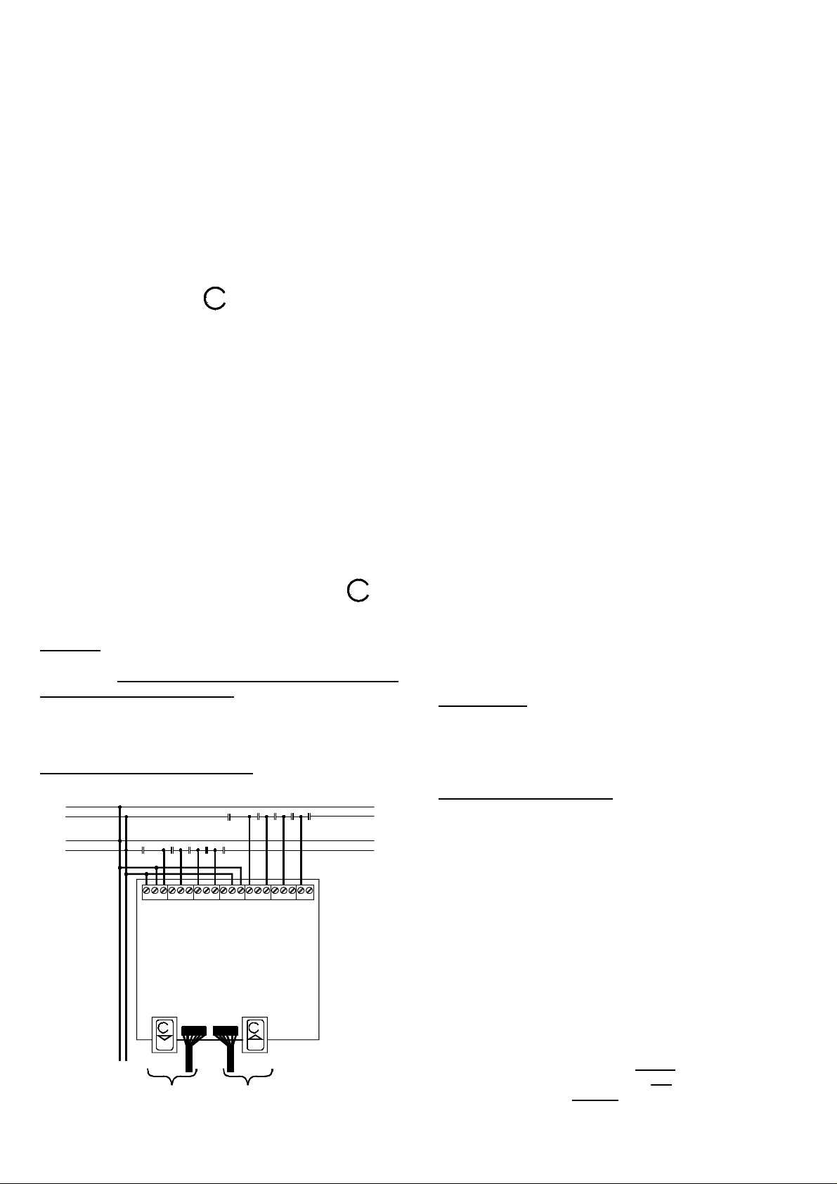
Connecting track sections:
Below draft clarifies how to connect the feedback module
RM-GB-8-N to a track.
Normalgleis
Überwachte Gleisbereiche
Monitored areas
IN1 IN2
7654321 8
RM-GB-8-N
Digitalstrom von
Digitalzentraler
oder Booster
Digital current from
command station
or booster
s88-N
OUT IN
Richtung
Digitalzentrale
Direktion to
command station
s88-N
Von weiteren
Rückmeldemodulen
From further
feedback modules
Digital current will be supplied to the RM-GB-8-N via input IN1
and IN2. IN1 provides current to the output 1 to 4 and IN2
provides current to the output 5 to 8. The two inputs IN1 and
IN2 are electrical separated.
Therefore will it be possible for example to supply IN1 from the
digital command station (control unit) and IN2 from a booster.
With reason to have a correct feedback report is it required to
supply digital current to both inputs (IN1 and IN2).
By using the control unit or a booster on IN1 or IN2 connect
the digital current for the supply of the continuous rail to
the clamp with the continuous white line.
Output clamps 1 to 8 shall be connected to those isolated
tracks, which shall be monitored. As indicated in the draft it is
sufficient to isolate one rail. The clamp with the dotted line
shall be connected to the rail track section to be monitored.
Detailed sample connections for various application can be
downloaded from our web-site (www.ldt-infocenter.com) within
the section "Downloads".
To avoid short circuits when locomotives are crossing the
transitions of each monitored track, always the same
connecting sequence of the tracks has to be strictly followed.
In case of a short circuit when crossing the transition (control
unit will switch to EMERGENCY STOP) please check the
connections and eventually change the cables of the monitored
track at the respective OUTPUT clamps.
Anti-interference capacitors can lead to an erroneous
occupied detection of the track and should therefore not be
used within the monitored track.
If you apply electrical resistant coating to the axles of your
trains you should measure the resistance value with a
Multimeter afterwards.
A resistance between 5 and 10 KOhm will guarantee a safe
monitoring by the occupied track detection of the feedback
module RM-GB-8-N.
Customary used resistance axles with a resistance value of
18 KOhm will just be monitored, provided that the rails are
very clean and the railway coaches have a sufficient contact
to the rails. In such case it will be recommended, to fit two
resistance axles to the coach to receive a total resistance
value of about 9 KOhm. This will assure a save monitoring
even when the rails are not perfect clean.
Accessory:
For easy assembly of the RM-GB-8-N-F below your model rail
road layout base plate we offer a set of assembly material
under the order identification: MON-SET. Under LDT-02 you
can purchase a low priced durable suitable case.
Trouble shooting:
What to do if something is not working as described above?
If you have purchased the RM-GB-8-N module as a kit, please
carefully check all parts and all soldered joints.
Important: Both inputs (IN1 and IN2) have to be connected to
a digital current.
Possibly test the single monitoring function of the modules first
before connecting it to the tracks.
To do this you can use a resistor (couple of hundred Ohm) or a
small model lamp to simulate the occupied situation on each
output clip.
Without resistor or incandescent lamp the detection of the
input should be indicated as “free”, with a resistor or
incandescent lamp your digital control unit or PC should show
an “occupied” situation. Made in Europe by
Littfinski DatenTechnik (LDT)
Kleiner Ring 9
D-25492 Heist/Germany
Phone: 0049 4122 / 977 381
Fax: 0049 4122 / 977 382
Subject to technical changes and errors. 07/2015 by LDT
Internet: http://www.ldt-infocenter.com
Märklin, and Motorola are registered trademarks.
 Loading...