

Littfinski DatenTechnik (LDT)
Operating Instruction
Light-Display-Module
for the
Light Control
connect the module via the “Kabel L@N” or via the screened
and therefore interference protected “Kabel Patch” (from
Light-Power Version 1.2 and Light-Display Version 1.7).
Light-Display-Modules contain 40 outputs with a maximum
load of 0.5 Ampere each. They are particular suitable for
switching light sources such as incandescent model railway
lamps or light emitting diodes (LED).
Light@Night and Light-DEC
Light-Display-F Part-No.: 050032
>> finished module <<
At least one Light-Display-Module and one Light-Interface
(LI-LPT or LI-LAN) will build together the hardware for the PC-
Layout-Light Control Light@Night.
The connection of a Light-Display-Module to a Light-DEC-
Basis-Module will create the basic unit for the
Layout Light Control Light-DEC.
Light-Display-Modules contain 40 light outputs with a
possible current load of 0.5 Ampere on each output .
The lighting effects (neon lamps, flashing blue light, light
chains, traffic lights and many others) can be assigned to 40
Suitable for analog and digital model railways.
This product is not a toy! Not suitable for children under 14 years of age! The kit
contains small parts, which should be kept away from children under 3! Improper
use will imply danger of injuring due to sharp edges and tips! Please store this
instruction carefully.
outputs.
CE Part-No.:
146 40 18
Introduction/Safety instruction:
You have purchased the Light-Display-Module for the Light
Control Light@Night and Light-DEC for your model railway.
The Light-Display-Module is a high quality product that is
supplied within the assortment of Littfinski DatenTechnik (LDT).
We are wishing you having a good time using this product.
The finished module comes with 24 month warranty.
• Please read the following instructions carefully. Warranty will
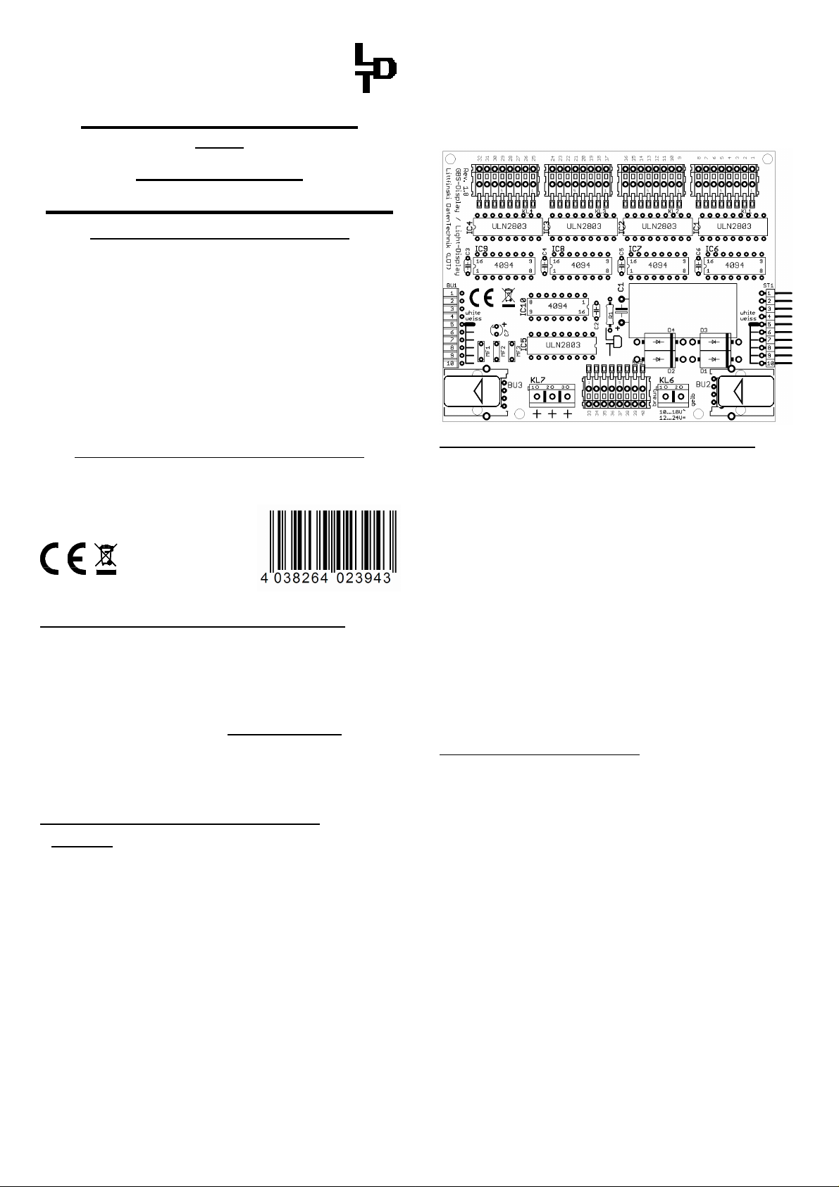
Connect the Light-Display-Module:
• Attention: Before starting the installation switch off the
• The Light-Display-Modules contain a large capacitor
Connect the Light-Display-Module to the Light-Interface (LILPT or LI-LAN), to the Light-DEC-Basic-Module or to the
already available Light-Power- or Light-Display-Modules via
the 10-poles pin-plug-bar.
The pin bar shall not be inserted in offset position to the
socket bar.
The modules are correct inserted whenever the pc-boards
are flash at the top and at the bottom. The pictures at the rear
side of this instruction show the correct position of the modules.
Light-Power- and Light-Display-Module do not need to be
connected directly to each other. It is as well possible to
expire due to damages caused by disregarding the operating
instructions. LDT will also not be liable for any consequential
damages caused by improper use or installation.
drive voltage by pushing the stop button or disconnect
the main supply.
which has to be completely discharged before the LightDisplay-Module can be connected or disconnected.
Please wait a couple of minutes after switching off the
supply transformer before you connect or disconnect the
Light-Display-Module.
OUT
IN
Voltage supply to the Display-Modules:
Each Light-Display-Module will get the voltage from a model
railway transformer via the clamp KL6.
The supply voltage can be between 10 and 18 Volt AC or
between 12 and 24 Volt DC.
If you use mainly light emitting diodes on your layout it is
possible that one 52VA transformer can supply more then
one Light-Display-Module. Picture 3 at the rear side of this
instruction shows how to arrange the supply of one
transformer to two Light–Display-Modules.
Please attend always to the same polarity (marked brown
and yellow) at the clamp KL6 of the connected Light-Display-
Module.
If you use incandescent lamps for illumination one 52VA
transformer can supply one Light-Display-Module. Also in
this case please attend always to the same polarity (marked
brown and yellow) at the clamp KL6 of the connected LightDisplay-Module (Picture 4 at the rear side of this instruction).
Connect the Illumination:
Each Light-Display-Module contains 40 outputs. Model
incandescent lamps can be directly connected. LED`s
require a serial resistor (about 4,7kOhm, depending to the
input voltage on KL6).
Each output can be loaded up to max. 0.5 Ampere. For
clamping a connection cable onto one of the 40 outputs please
press carefully down the white lever and insert the cable from
the top into the clamp.
If the Light-Display-Module will be supplied with AC-voltage is
the DC-voltage at the 40 outputs about (1,414 * input voltage)
– 1.4 Volt. An AC input voltage of e.g. 15 Volt (on KL6) will give
a DC-voltage of about 20 Volt at the outputs.
If the Light-Display will be supplied with DC voltage on KL6
the output DC voltage will be lower by about 1,4 Volt related
to the input voltage. The interrelation between input and output
voltage will be shown on table 1 at the rear side of this
instruction.
The common positive pole for all outputs is clamp KL7
(Picture 1 at the rear side).
The common positive pole contains three inputs which can
be loaded with 1 Ampere each. Distribute the common
positive connection of the lamps and LED`s evenly to the three
positive clamps KL7 (Picture 2 at the rear side).
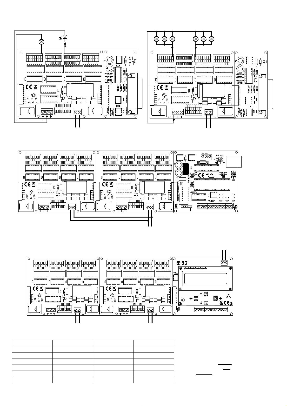
Picture 1: Incandescent lamps can be connected directly. For
From transformer
Light Emitting Diodes it is absolutely required to use a serial
resistor (about 4,7kOhm, related to the input voltage at KL6).
Leuchtdiode
GBS-Display / Light-Display
Rev. 1.8
Littfinski DatenTechnik (LDT)
Modellbahnlämpchen
model incandescent
lamp
26272829303132
25
KL4 KL3 KL2 KL1
18192021222324
17
light-emitting diode
Vorwiderstand
series resistor
9
10111213141516
45678
123
Light Interface (LPT)
Rev. 1.0
Littfinski DatenTechnik (LDT)
C2
IC1
C1
Printer
Port
LPT
Picture 2: Each of the 40 light outputs can be loaded by up to
max. 0,5 Ampere. Each input of the three positive clamps (KL7)
can be loaded with max. 1 Ampere.
max. 0,5 Ampere
GBS-Display / Light-Display
Rev. 1.8
Littfinski DatenTechnik (LDT)
45678
26272829303132
25
KL4 KL3 KL2 KL1
18192021222324
17
9
10111213141516
123
C2
C1
Light Interface (LPT)
Rev. 1.0
Littfinski DatenTechnik (LDT)
IC1
Printer
Port
LPT
BU1
white
weiss
OUT
KL7
BU3
KL5
KL6
braun
10...18V~
39383736353433
40
12...24V=
braun
brown
Vom Modellbahntrafo
From transformer
BU2
gelb
yellow
gelb
BU1
ST1
white
weiss
IN
BU2
IC4
IC3
IC2
BU1
white
weiss
OUT
KL7
BU3
max. 1 Ampere
KL5
KL6
BU2
braun
gelb
10...18V~
39383736353433
40
12...24V=
braun
gelb
brown
yellow
BU1
ST1
white
weiss
IN
Vom Modellbahntrafo
BU2
IC4
IC3
IC2
Picture 3: If you illuminate your layout mainly with Light Emitting Diodes one 52 VA transformer can supply more then one LightDisplay-Module. In this case attend always to the same polarity (marked brown and yellow) at the clamp KL6 of the connected LightDisplay-Modules.
DMX
GBS-Display / Light-Display
Rev. 1.8
Littfinski DatenTechnik (LDT)
BU1
white
weiss
OUT
26272829303132
25
KL4 KL3 KL2
KL7
BU3
KL5
39383736353433
45678
9
101112131415161819202122232417
KL6
braun
10...18V~
40
12...24V=
123
GBS-Display / Light-Display
Rev. 1.8
Littfinski DatenTechnik (LDT)
KL1
BU1
ST1
white
white
weiss
weiss
BU2
gelb
OUT
IN
26272829303132
25
KL4 KL3 KL2
KL7
BU3
KL5
39383736353433
KL6
braun
10...18V~
40
12...24V=
braun
brown
Vom Modellbahntrafo
From transformer
45678
9
101112131415161819202122232417
gelb
yellow
123
IC7
D1
C2
KL1
C1
C4
IC8
ST1
BU1
C11
C21
white
weiss
BU2
IN
gelb
IC2
RN2
RN1
Littfinski DatenTechnik (LDT)
IC5
Q1
C6
L1
C9
IC6
C3
KL1 KL2 KL3 KL4
ST1
8
+5V
PC/
LAN
BU2
Trxcom
C8
KL5
C5
PC
LAN-Schnittstelle
(Interface)
CR1
C10
IC1
C20
C17
C18
IC3
C19
Taster
C14
C12
C15
C13C16
1234567
GND
Rev. 1.0
Light-LAN (Ethernet Interface)
Picture 4: If you illuminate your layout with incandescent lamps one 52VA transformer can supply one Light-Display-Module. If
possible please use only transformers from the same manufacturer and attend to the same polarity (marked brown and yellow) at the
clamp KL6 of the connected Light-Display-Modules.
45678
GBS-Display / Light-Display
Rev. 1.8
Littfinski DatenTechnik (LDT)
26272829303132
25
KL4
KL3 KL2 KL1
9
101112131415161819202122232417
123
Littfinski DatenTechnik (LDT)
GBS-Display / Light-Display
Rev. 1.8
braun
45678
26272829303132
25
KL4
KL3 KL2 KL1
9
101112131415161819202122232417
123
D1
brown
J
K
rot
red
K J
red brown
Optional:
Von DCC-Digitalzentrale
oder Booster
From DCC command station
or booster
KL5
Light-DEC V1.0
IC5
12:15:00 T 300
white
weiss
IN
BU1
ST1
Littfinski DatenTechnik (LDT)
Light-DEC-Service
Rev. 1.0
Littfinski DatenTechnik (LDT)
Light-DEC-Basis
Rev. 1.0
S2
S3
KL1 KL2 KL3 KL4
+5V
S1
S4
8
Taster / Button
R1
1234567
GND
BU1
white
weiss
KL7
OUT
BU3
Colored sample connections can be found on our Web-Site www.ldt-infocenter.com at the section “Sample Connections”.
KL5
KL6
braun
10...18V~
39383736353433
40
12...24V=
braun
brown
Vom Modellbahntrafo
From transformer
BU2
gelb
yellow
gelb
BU1
ST1
white
white
weiss
weiss
OUT
IN
KL7
BU3
KL5
KL6
braun
10...18V~
39383736353433
40
12...24V=
braun
brown
Vom Modellbahntrafo
From transformer
BU2
gelb
yellow
gelb
Table 1:
Input Voltage (KL6) Output Voltage Input Voltage (KL6) Output Voltage
AC-Voltage DC-Voltage DC-Voltage DC-Voltage
10 V AC 12,7 V DC
12 V AC 15,6 V DC 12 V DC 10,6 V DC
15 V AC 19,8 V DC 15 V DC 13,6 V DC
16 V AC 21,2 V DC
18 V AC 24,0 V DC 24 V DC 22,6 V DC
Littfinski DatenTechnik (LDT)
D-25492 Heist/Germany
Phone: 0049 4122 / 977 381
Fax: 0049 4122 / 977 382
Internet: http://www.ldt-infocenter.com
Subject to technical changes and errors. 06/2016 by LDT
Made in Europe by
Kleiner Ring 9
 Loading...