

Littfinski DatenTechnik (LDT)
Control
Module
Module
Power) which
to the side of the
40
5
max.
Module can be up to
various light
,
light control and
can be assigned
Kleiner Ring 9 • 25492 Heist/Germany • Phone: 0049 4122 / 977 381 • Fax: 0049 4122 / 977 382
Basic Manual
Light-DEC
The Light-DEC is a universal Layout-Light-Control for
analogue and digital model railway layouts from the
Digital-Professional-Series!
Various light-functions can be assigned to up to 160 light-
outputs and can be automatically controlled within the
daylight-cycle or can be switched ON or OFF via push buttons
or DCC-Commands.
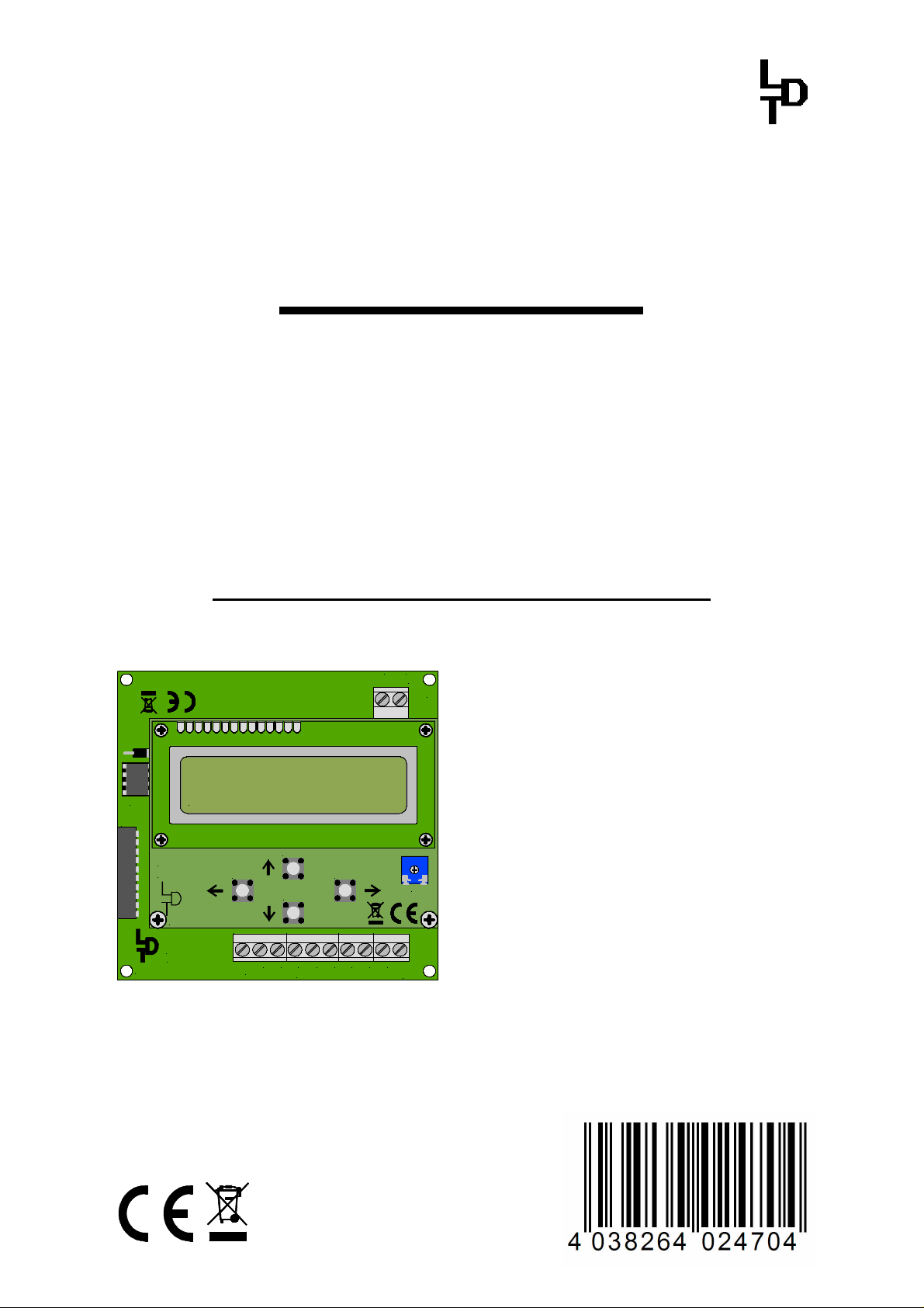
Light-DEC-Basic-F Part-No.: 810222
>> Basic-Module as finished module <<
K J
red brown
D1
Light-DEC V1.0
IC5
BU1
Littfinski DatenTechnik (LDT)
This product is not a toy! Not suitable for children under 14 years. Improper use will imply danger or injuries due to
sharp edges and tips! Please store this instruction carefully.
12:15:00 T 300
Light-DEC-Service
Rev. 1.0
Littfinski DatenTechnik (LDT)
Light-DEC-Basis
Rev. 1.0
S3
KL1 KL2 KL3 KL4
S2
S4
7
8
+5V
S1
4
5
6
Taster / Button
R1
1
2
3
GND
The universal Layout-Light-
KL5
Light-DEC consist of one Basicand as minimum of one Light(Light-Display or Lighthas to be plugged on
Basic-Module.
Light-Display-Modules contain
outputs, which can cover a load of 0.
Ampere each. Light-Power-Module with
24 outputs can supply a current of
2.5 Ampere each output.
With one Basic-
160 light outputs via max. 7 LightModules controlled. The
effects (Neon-lamps, Flash-lights
Running-lights, Trafficmany others)
individual to the particular outputs.
CE Part-No.:
146 40 16

Layout-Light-Control Light-DEC – Manual
Content: Page
1. Introduction / Safety Instruction 2
2. Connect the Basic-Module to the first Light-Module 3
2.1. Using further Light-Modules 4
2.2. Connect light sources to the Light-Modules 5
3. Connect push-buttons or switches to the Basic-Module 7
4. Connect the Basic-Module with the digital layout 7
5. First starting-up / selecting language 8
5.1. Register external push-buttons or switches 9
5.2. Register used Light-Modules at the Basic-Module 10
5.3. Light source test 11
6. Adjusting start time for day-sequence of the light control 11
6.1. Selecting start options of the light control 12
6.1.1 Start/stop of Light-DEC via external push buttons/switches 13
6.1.2 Start/stop of Light-DEC via DCC-Addresses 13
7. Day-phases: select start timing and time-factors for daybreak,
day, dusk and night 14
8. Setup of switch groups and switch times 15
9. Available light functions 17
10. Light adjustment: individually matching of parameters of
light-functions 17
10.1. Light adjustments: traffic light pedestrian, traffic light
cross-road, traffic light circuit 18
11. Output function: assign light functions to the output of
light-modules 19
11.1. Output function: properties always active 20
11.2. Output function: properties switch group 20
11.3. Output function: properties push button/switch 21
11.4. Output function: properties DCC-address 21
11.5. Output function: night function for traffic light pedestrian
and traffic light cross road 22
12. Factory setting 22
- 1 -
Layout-Light-Control Light-DEC – Manual
1. Introduction/Safety instruction
You have purchased the Basic-Module for the Layout-Light Control Light-DEC for
your model railway.
The Basic-Module is a high quality product that is supplied within the assortment of
Littfinski DatenTechnik (LDT).
We are wishing you having a good time using this product.
The finished module comes with 24 month warranty.
• ·Please read the following instructions carefully. Warranty will expire due to
damages caused by disregarding the operating instructions. LDT will also not be
liable for any consequential damages caused by improper use or installation.
• Each Light-DEC-Basic-Module will be supplied together with a Technical Manual. It
contains a graphic menu navigation and tables. We have separated those
information at your ease to prevent the requirement of searching on different
pages within this manual.
• At the section “Downloads” on our Web-Site (www.ldt-infocenter.com) you can
find this Basic Manual and the Technical Manual as PDF-File with colored
illustrations. You can open, download and print it with the Acrobat Reader.
Many illustrations at this manual are identified with a file name (e.g. page_1611).
You can find those files on our Web-Site at the section “Sample Connections” of
the Layout-Light-Control Light-DEC. You can download the files as PDF-File and
make a colored print at the DIN A4 format.
• Attention: Perform all connection-work only after disconnect the model railway
layout from mains (disconnect all main-plugs of model railway transformers
and switched mode power supplies or switch off the socket strips).
• The Light-Display-Modules contain a large capacitor, which has to be
completely discharged before the Light-Display-Module can be connected or
disconnected. Please wait a couple of minutes after switching off the supply
transformer before you connect or disconnect the Light-Display-Module.
Optional:
Von DCC-Digitalzentrale
oder Booster
From DCC command station
or booster
J
max. 2,5 A max. 2,5 A
16151413121110
987654321
GBS-Display / Light-Display
Rev. 1.8
Littfinski DatenTechnik (LDT)
KL1 KL2 KL3 KL4 KL5 KL6 KL7
max. 0,5 Ampere
26272829303132
25
KL4 KL3 KL2 KL1
8
9
101112131415161819202122232417
1234567
D1
Light-DEC V1.0
IC5
Light-Power
Rev. 1.2
BU1
white weiss
OUT
BU3
KL8
KL10 KL11
KL9
17181920212223
12 ... 24 V DC
24
- +
12...24V DC
Littfinski DatenTechnik (LDT)
KL12
ST1
BU1
white
white weiss
weiss
BU2
IN
OUT
BU3
KL7
max. 1 Ampere
KL5
KL6
braun
10...18V~
39383736353433
40
12...24V=
braun
brown
Vom Modellbahntrafo
From transformer
gelb
yellow
ST1
white
weiss
BU2
IN
gelb
12:15:00 T 300
BU1
Light-DEC-Service
Rev. 1.0
Littfinski DatenTechnik (LDT)
Light-DEC-Basis
Rev. 1.0
Littfinski DatenTechnik (LDT)
S2
S3
S4
KL1 KL2 KL3 KL4
8
+5V
Taster / Button
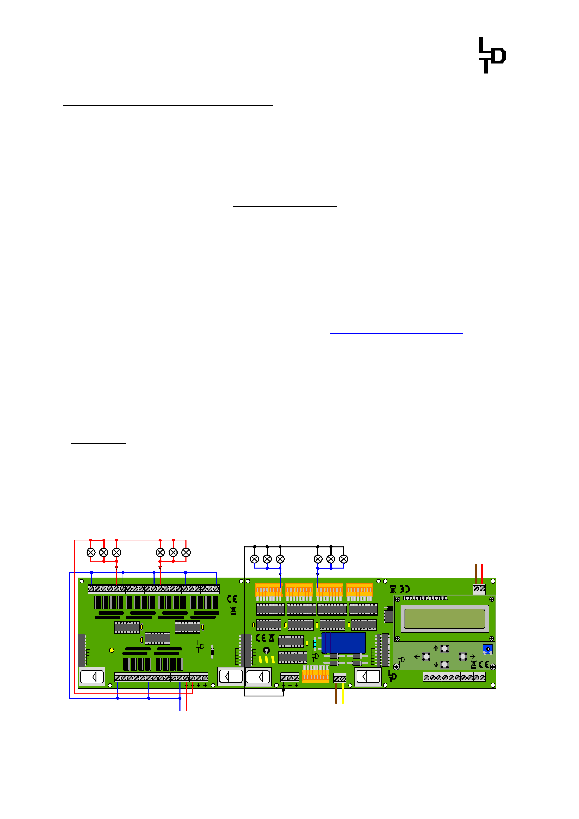
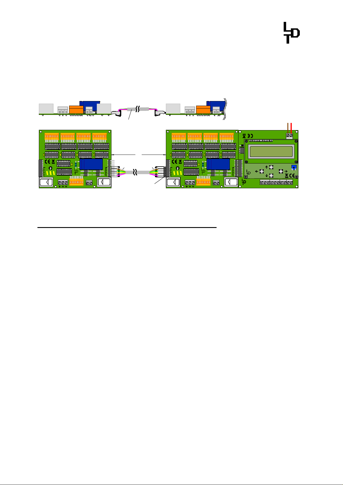
page_1611
The Light-DEC Basic-Module (right) in connection to one Light-Display- (middle) and one Light-
Power-Module (left).
K
braun
rot
brown
red
K J
red brown
KL5
S1
R1
1234567
GND
- 2 -
Layout-Light-Control Light-DEC – Manual
2. Connect the Basic-Module with the first Light-Module
Connect the Basic-Module via the 10-poles socket bar BU1 either with a LightDisplay- or a Light -Power-Module. It is essential to attend careful to the position of
the pin bar of the Light-Display- and the Light-Power-Module and that there is no
offset to the socket bar of the Basic–Module. If the printed circuit boards of the
Basic- and Light-Module are inserted into a position that they are flush on top and
bottom both modules are correctly connected.
Optional:
Von DCC-Digitalzentrale
oder Booster
From DCC command station
or booster
J
K
braun
rot
brown
red
K J
red brown
KL5
GBS-Display / Light-Display
Rev. 1.8
Littfinski DatenTechnik (LDT)
Modellbahnlämpchen
model incandescent
lamp
26272829303132
25
18192021222324
17
Leuchtdiode
light-emitting diode
Vorwiderstand
series resistor
9
10111213141516
8
1234567
BU1
white
weiss
OUT
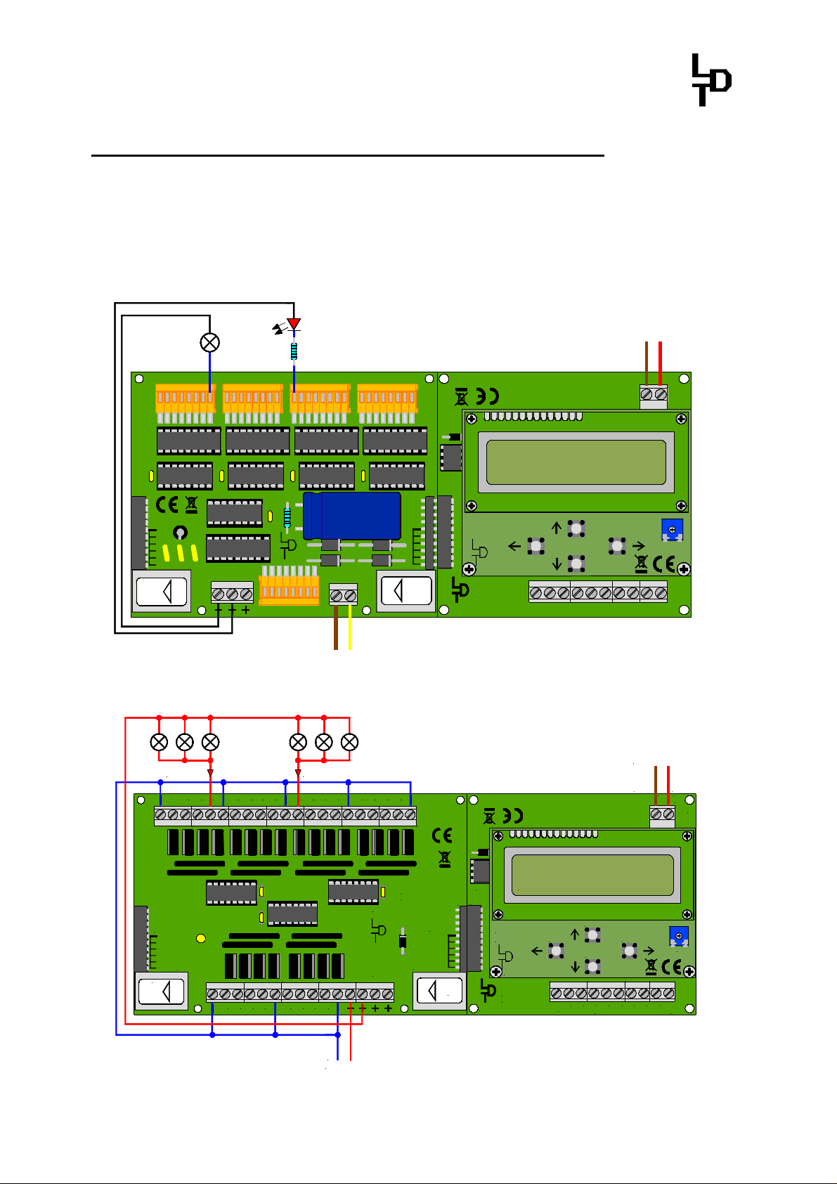
page_1601
The Light-DEC Basic-Module with the first directly connected Light-Display-Module.
max. 2,5 A max. 2,5 A
BU1
white weiss
OUT
KL4 KL3 KL2 KL1
KL5
BU3
161514
BU3
KL8
KL7
13
121110
KL9
171819
9
KL10 KL11
20
KL6
braun
10...18V~
39383736353433
40
12...24V=
braun
brown
Vom Modellbahntrafo
From transformer
876
212223
24
5
12 ... 24 V DC
BU2
gelb
gelb
yellow
432
Littfinski DatenTechnik (LDT)
KL12
ST1
white
weiss
IN
1
KL1 KL2 KL3 KL4 KL5 KL6 KL7
Light-Power
Rev. 1.2
white weiss
BU2
D1
IC5
BU1
Light-DEC-Service
Rev. 1.0
Littfinski DatenTechnik (LDT)
Light-DEC-Basis
Rev. 1.0
Littfinski DatenTechnik (LDT)
D1
IC5
BU1
ST1
IN
Littfinski DatenTechnik (LDT)
Light-DEC V1.0
12:15:00 T 300
S2
S4
6
7
Taster / Button
S2
S4
7
8
S1
4
5
5
6
Taster / Button
S3
KL1 KL2 KL3 KL4
8
+5V
Light-DEC V1.0
12:15:00 T 300
Light-DEC-Service
Rev. 1.0
Littfinski DatenTechnik (LDT)
Light-DEC-Basis
Rev. 1.0
S3
KL1 KL2 KL3 KL4
+5V
R1
1
2
3
GND
Optional:
Von DCC-Digitalzentrale
oder Booster
From DCC command station
or booster
J
K
braun
rot
brown
red
K J
red brown
KL5
S1
R1
1
234
GND
page_1608
The Light-DEC Basic-Module with the first directly connected Light-Power-Module.
- +
12...24V DC
- 3 -
Layout-Light-Control Light-DEC – Manual
The first Light-Module has to be always directly connected onto the Basic-Module
for voltage supply.
Attend as well to the separate Operation Instruction of the Light-Display- or LightPower-Module.
At the Operation Instruction you can find as well basic instruction for the
connection of the power supply and the connection of model incandescent lamps
or light emitting diodes (LED) within the section ”Connection of Illumination”.
2.1. Using further Light-Modules
Via the Basic-Module is it possible to control with max. 7 Light-Modules up to 160
light-ouputs. A variable combination of Light-Display- and Light-Power-Modules is
possible.
A Light-Display-Module contains 40 and a Light-Power-Module 24 outputs. If there
are only Light-Power-Modules connected can be with 7 of those Modules (7 x 24 =
168 light-outputs) used. The last 8 outputs of the seventh Light-Power-Module
cannot be used for control connection because the maximum quantity of 160 light
outputs will be exceeded by 8.
If there are only Light-Display-Modules used with 40 outputs each there can be 4 of
those modules (4 x 40 = 160 light-outputs) used at the Basic-Module.
Combined used can be 5 to 7 Light-Modules used on one Basic-Module. If the
summary will be more than 160 light outputs will be the surplus outputs not
controlled.
The Light-Modules shall be connected directly next to each other as shown at the
illustration on page 2 with one Light-Display- and one Light-Power-Module each.
If the Light-Modules shall be installed at an extended situation to be closer to the
light sources there shall be shielded interference-protected patch-cables
(computer network cable) used for the connection.
1234567
8
GBS-Display / Light-Display
Rev. 1.8
Littfinski DatenTechnik (LDT)
BU1
white
weiss
OUT
1234567
8
26272829303132
25
KL4
KL3 KL2 KL1
KL7
BU3
9
101112131415161819202122232417
ST1
white
weiss
KL5
KL6
BU2
braun
10...18V~
39383736353433
40
12...24V=
IN
gelb
xm
Bestellbezeichnung /
Order code: Kabel Patch xm
GBS-Display / Light-Display
Rev. 1.8
Littfinski DatenTechnik (LDT)
BU1
white
weiss
OUT
26272829303132
25
KL4
KL3 KL2 KL1
KL7
BU3
9
101112131415161819202122232417
D1
Light-DEC V1.0
IC5
12:15:00 T 300
BU1
ST1
white
weiss
Light-DEC-Service
Rev. 1.0
S3
KL5
KL6
BU2
braun
gelb
10...18V~
39383736353433
40
12...24V=
IN
Littfinski DatenTechnik (LDT)
Light-DEC-Basis
Rev. 1.0
Littfinski DatenTechnik (LDT)
KL1 KL2 KL3 KL4
+5V
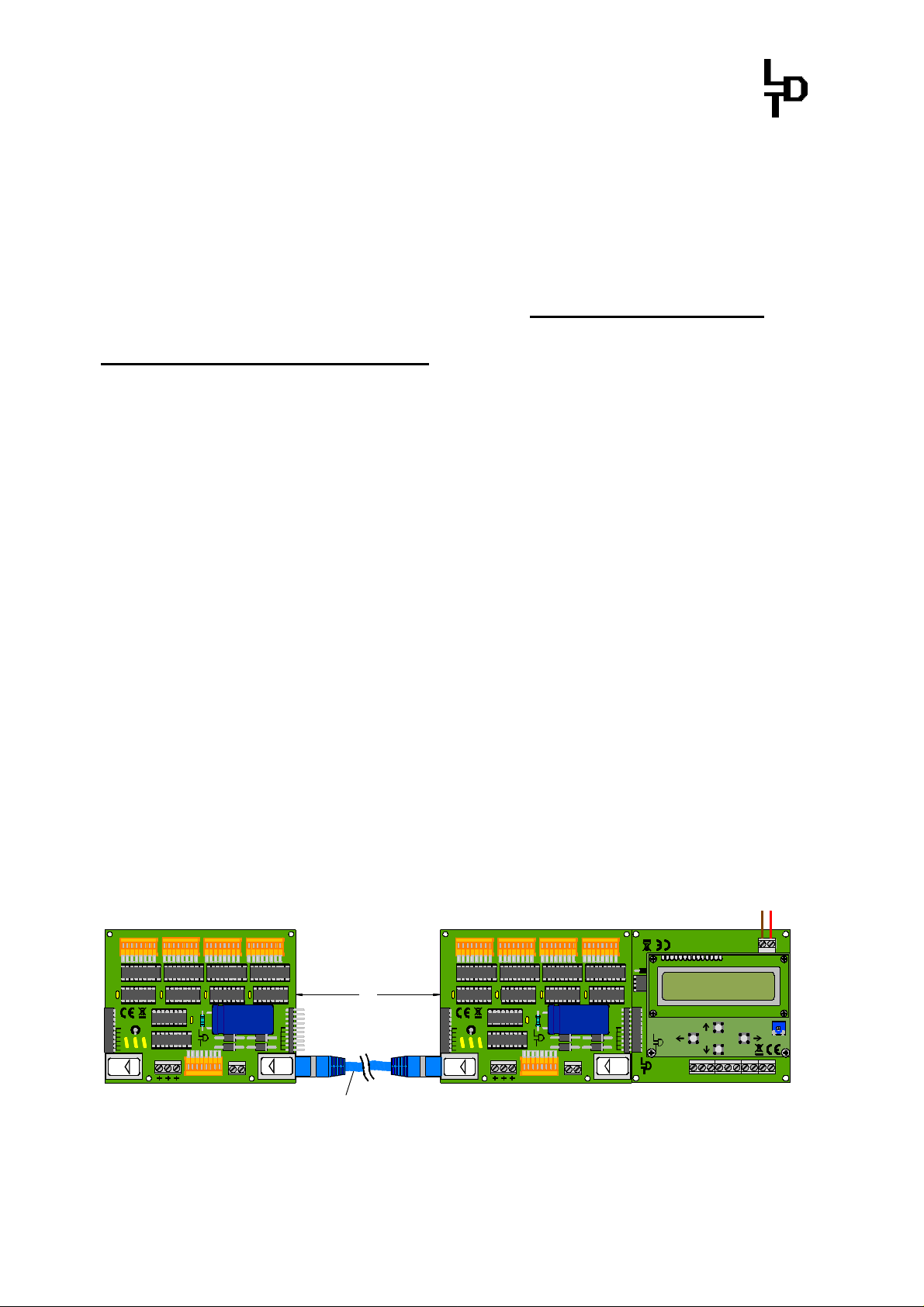
page_1607
The second Light-Display-Module has been connected to the first Module via a Patch-Cable.
S2
S4
8
Optional:
Von DCC-Digitalzentrale
oder Booster
From DCC command station
or booster
braun
brown
S1
Taster / Button
J
K
rot
red
K J
red brown
KL5
R1
1234567
GND
- 4 -
Layout-Light-Control Light-DEC – Manual
It is as well possible to connect the Light-Modules to each other via the “Kabel
Light@Night” at a distance of 0.5m, 1m or 2m.
On this way can be as well older Light-Modules without RJ-45 sockets for a patch-
cable connection connected to each other on a longer distance of up to 2m.
Optional:
Von DCC-Digitalzentrale
oder Booster
From DCC command station
Bestellbezeichnung /
Order code: Kabel Light@Night xm
1234567
8
26272829303132
25
GBS-Display / Light-Display
Rev. 1.8
Littfinski DatenTechnik (LDT)
KL4 KL3 KL2 KL1
BU1
white
weiss
KL7
OUT
BU3
1234567
8
9
101112131415161819202122232417
weiss
white
xm
weiss
white
Stiftleiste (Adapter)
pin plug (adapter)
ST1
white
weiss
KL5
KL6
BU2
braun
10...18V~
39383736353433
40
12...24V=
IN
gelb
26272829303132
25
GBS-Display / Light-Display
Rev. 1.8
Littfinski DatenTechnik (LDT)
KL4 KL3 KL2 KL1
BU1
white
weiss
KL7
OUT
BU3
9
101112131415161819202122232417
D1
Light-DEC V1.0
IC5
12:15:00 T 300
BU1
ST1
white
weiss
Light-DEC-Service
Rev. 1.0
S3
KL5
KL6
BU2
braun
gelb
10...18V~
39383736353433
40
12...24V=
IN
Littfinski DatenTechnik (LDT)
Light-DEC-Basis
Rev. 1.0
Littfinski DatenTechnik (LDT)
KL1 KL2 KL3 KL4
+5V
page_1606
The second Light-Display-Module has been connected to the first Module via a Kabel
Light@Night.
2.2. Connect light sources to the Light-Modules
Some light-functions require only one light source (model railway incandescent
lamps or light emitting diodes – LED). Maximum is 10 light sources for the lightfunction traffic-light cross-road.
If one light-function requires more than one light-source those have to be connected
to the clamps of the Light-Modules in series and ascending sequence.
For the light-function of Running Light 4 and 5, Fun-Fair and Construction Work 5
and 8 shall be the light-sources in series connected to the clamps at the sequence
of the actual installed situation.
The light-function Control-Center requires 3 light-sources, which have to be
implemented into the control center to simulate the light of a switch panel. The
first clamp shall be connected to the red, the second to the green and the third to
the yellow light-source.
3 light-sources are required for the light-function TV-Set which have to be installed
into the TV-room for simulation of a running TV-Set. The first clamp shall be
connected to the red, the second to the green and the third to the blue light-source.
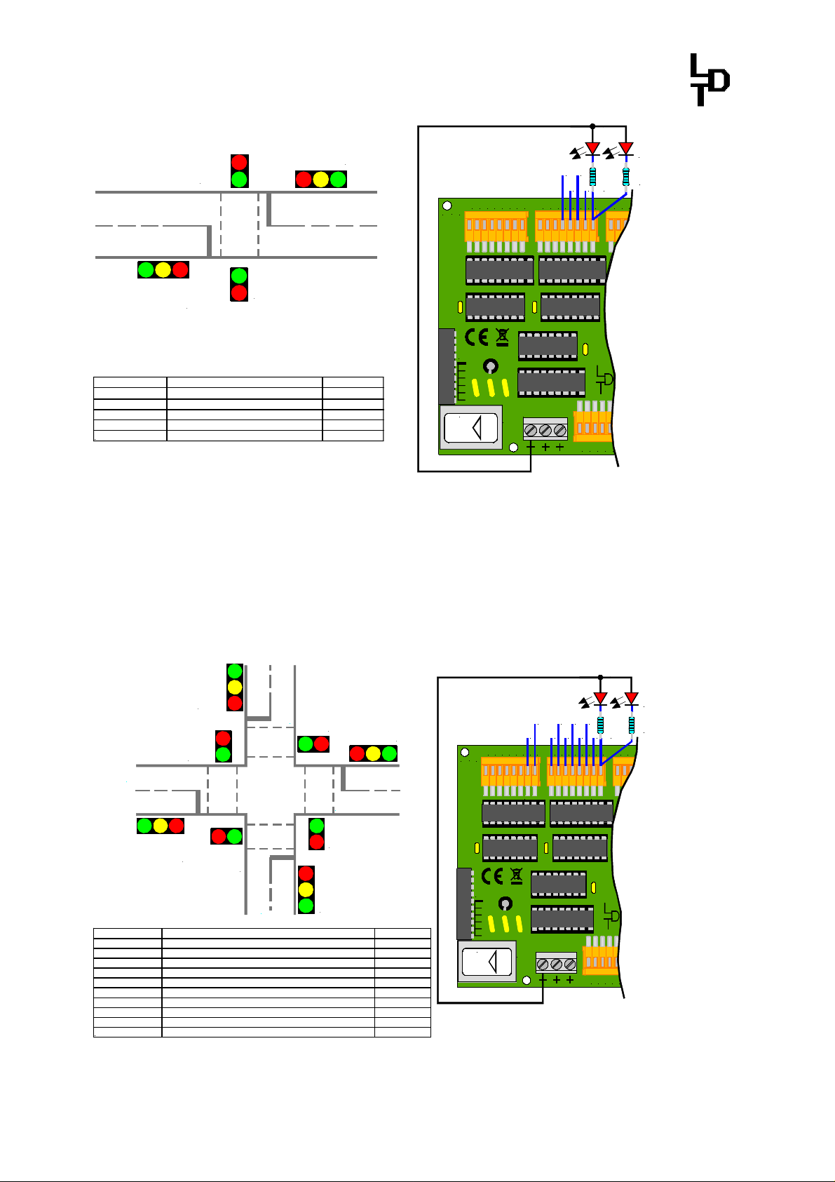
The light-function Traffic-Light Pedestrian occupies 5 clamps but provides via
those clamps voltage to 10 light -sources. There shall be 2 light-sources connected
to one clamp. Both Pedestrian- and both Traffic-road lights will be electrical
parallel switched on this way because they will show always the same light phases.
For the correct function is it required that the traffic-light-sources have to be
connected to the correct clamps.
The following illustration shows, which light-source has to be wired to which
clamp of the Light-Module.
or booster
J
K
braun
rot
brown
red
K J
red brown
KL5
S2
S1
S4
8
Taster / Button
R1
1234567
GND
- 5 -
Layout-Light-Control Light-DEC – Manual
Leuchtdiode
K
3736353433
light-emitting diode
Vorwiderstand
series resistor
141516
K
K+1
K+3
K+4
K+2
GBS-Display / Light-Display
Rev. 1.8
Littfinski DatenTechnik (LDT)
K+4
K+3
26272829303132
25
KL4 KL3
K+2
K+1
18192021222324
17
K+4
K+2
K+1
K
Ausgang / Output Bezeichnung / Function Farbe / Color
K Straße Rot / road red Rot / red
K+1 Straße Gelb / road yellow Gelb / yellow
K+2 Straße Grün / road green Grün / green
K+3 Fußgänger Rot / pedestrian red Rot / red
K+4 Fußgänger Grün / pedestrian green Grün / green
K+3
BU1
white
weiss
OUT
BU3
KL7
page_1678
Connection of Pedestrian Traffic-Light (Light –function Traffic-Light Pedestrian) with light
emitting diodes to a Light-Display-Module (LDM).
The light-function Traffic-Light Cross-Road creates all required traffic-light
sequences for cross-roads and road-intersections.
Up to 20 light-sources will be supplied via 10 clamps from one Light-Module. Two
light-sources each shall be connected to one clamp.
Which light-source has to be wired to which clamp shows the following illustration.
K+7
K+6
K+5
K+3
K+4
Hauptstraße
K+9
K+8
K+4
K+2
K+6
K+8
K+3
K+1
K+7
K+5
26272829303132
K+9
25
18192021222324
K
K+1
K+2
GBS-Display / Light-Display
Rev. 1.8
Littfinski DatenTechnik (LDT)
K
17
Leuchtdiode
light-emitting diode
Vorwiderstand
series resistor
141516
Nebenstraße
minor road
KL4 KL3
K+4
K+3
K+2
K+1
K
K+8
K+9
K+5
K+6
main road
Ausgang / Output Bezeichnung / Function Farbe / Color
K Nebenstraße Rot / minor road red Rot / red
K+1 Nebenstraße Gelb / minor road yellow Gelb / yellow
K+2 Nebenstraße Grün / minor road green Grün / green
K+3 Fußgänger Nebenstr. Rot / pedestrian minor road red Rot / red
K+4 Fußgänger Nebenstr. Grün / pedestrian minor road green Grün / green
K+5 Hauptstraße Rot / main road red Rot / red
K+6 Hauptstraße Gelb / main road yellow Gelb / yellow
K+7 Hauptstraße Grün / main road green Grün / green
K+8 Fußgänger Hauptstr. Rot / pedestrian main road red Rot / red
K+9 Fußgänger Hauptstr. Grün / pedestrian main road green Grün / green
page_1679
K+7
BU1
white
weiss
BU3
KL7
3736353433
OUT
Connection of a traffic-light system of a cross-road (Light-function traffic-light cross-road) with
light emitting diodes to a Light-Display-Module.
- 6 -

Layout-Light-Control Light-DEC – Manual
From DCC command station
3. Connect push-buttons or switches to the Basic-Module
The Basic-Module contains a 10-poles clamp bar for the connection of up to 8 PushButtons or Switches. Via those external push-buttons or switches is it possible to
start or stop manually the Light-Control Light-Dec or single light-functions.
Optional:
Von DCC-Digitalzentrale
oder Booster
or booster
J
braun
brown
K
rot
red
K J
red brown
KL5
GBS-Display / Light-Display
Rev. 1.8
Littfinski DatenTechnik (LDT)
Modellbahnlämpchen
model incandescent
lamp
26272829303132
25
18192021222324
17
Leuchtdiode
light-emitting diode
Vorwiderstand
series resistor
9
10111213141516
8
1234567
KL4 KL3 KL2 KL1
D1
Light-DEC V1.0
IC5
BU1
white
weiss
ST1
IN
Littfinski DatenTechnik (LDT)
BU1
white
weiss
KL5
OUT
BU3
KL7
KL6
BU2
braun
gelb
10...18V~
39383736353433
40
12...24V=
braun
brown
Vom Modellbahntrafo
From transformer
gelb
yellow
page_1612
Up to 8 push-buttons or switches can be connected to the 10 poles clamp bar of the Basic-
Module.
One pole of the push buttons or switches has to be always connected to the earth
terminal, which is marked with “GND”. The second pole shall be connected to one
of the clamp 1 to 8. The clamp “+5V” will not be required by use of push-buttons or
switches.
If a light-function is assigned to a push-button will the function be started with the
first keystroke and stopped with the second keystroke. If a switch will be used will
be the function active as long as the switch will be in “ON” position.
If there are push buttons or switches connected can be individually transmitted to
the basic module for each of the 8 inputs (as described at section 5.1).
The factory setting for all 8 inputs is adjusted to push buttons.
12:15:00 T 300
Light-DEC-Service
Rev. 1.0
Littfinski DatenTechnik (LDT)
Light-DEC-Basis
Rev. 1.0
S2
S3
KL1 KL2 KL3 KL4
7
8
+5V
S1
S4
4
5
6
Taster / Button
Taster oder Schalter
Push button or switch
R1
1
2
3
GND
4. Connect the Basic-Module with the digital layout
If you want to start and stop the Light-Control Light-DEC or single output-
functions digital via DCC-addresses the Basic Module requires digital
informations.
Those receive it via the connection clamp KL5 as shown at the sampleconnections on page 1 to 5. Supply the basic module with digital voltage directly
from the digital central unit with integrated booster or from an external booster or
from the digital ring-conductor “Switching” because then will be interference-
protected data available.
- 7 -
Layout-Light-Control Light-DEC – Manual
>
English
<
Do not supply the digital voltage for the Basic-Module directly from the rails.
DCC-Digital systems are using different cable colors or designations for both
digital cables. Mostly used markings are printed next to clamp 5 but do not
necessarily to be used because the Basic-Module will automatically evaluate the
correct DCC-digital signal.
5. First starting-up / selecting language
As soon as the first Light-Module which has been
directly plugged onto the Basic-Module receives
power supply the operation status will be
indicated at the display with a short delay:
If the Display does not correct indicate during first starting -up you should turn with
help of a small screwdriver carefully the potentiometer P1. This Potentiometer is
located at the right side below the display has to be turned halfway left or right until
the information on the display can be optimal read.
For the first 40 light-outputs are output-functions set ex-factory, which will be
started at random within the first 15 seconds after switching-on the unit. If you have
installed some light sources onto the first 40 light outputs those will now lighten
and flash on different intervals.
The starting of the light-functions at random after switching-on provides an
optimal optical impression because multiple installed light functions shall not be
running synchronized.
Within the Technical Manual you can find at the section “Output-Functions /
Factory setting” a table which indicates the assignment of output functions to the
related clamps set ex-factory.
VX.X at the Display of the Operation Display indicates the firmware version of the
Basic-Module. More information about the lower line of the display can be found at
the following pages of this manual.
Below the Display you can find 4 push-buttons indicated with arrows for the
directions LEFT, RIGHT, ABOVE and BELOW. Within the further description those
keys will be indicated as LEFT, RIGHT, ABOVE and BELOW.
The Technical Manual includes a graphical Menu Navigation to illustrate the steps
through the menus parallel to the following descriptions.
Depress now the key RIGHT longer as three
seconds. The display changes into the Main
Menu and all light sources will be switched off:
Ex-factory has been the language “Deutsch” reselected. If you don’t want to
change the language just skip the following lines and carry on reading with chapter
5.1.
If you want to select the language “Deutsch” just
activate the key RIGHT. The display will indicate
the actual selected language:
Light-DEC VX.X
22:30:00 A 300
---Main Menu---Language
Language
- 8 -
Layout-Light-Control Light-DEC – Manual
>
Deutsch
<
With the keys ABOVE or BELOW you can switchover between >Deutsch< and >English<.
Leave the language selection with the key LEFT
for using now the selected language.
If you would have selected >Deutsch< the display
would show now:
5.1. Register external push-buttons or switches
Depress within the main menu several times
shortly the key BELOW until the display shows:
To register the used external push buttons or
switches depress again the key RIGHT. The
Display shows the actual setting for the input 1:
With the keys ABOVE or BELOW you can select
one of the 8 inputs. The actual setting (switch or
push button) will be indicated matched to the
input (e.g. input 7):
Ex factory are all 8 inputs set for push buttons.
General: values between a bigger- and smaller sign (> <) can be edited with the
keys ABOVE or BELOW step-wise with single keystrokes.
Is the value range for the selection of a very large value (e.g. for a time selection)
will be the editing value indicated with curly braces (} {). If the keys ABOVE or
BELOW will be activated for a longer duration as 2 seconds the adjustable values
at the display will keep running until the key will be released.
If you want to change the setting of an input you have at first to select via ABOVE or
BELOW the number of the input (e.g. position 3).
Activate now the key RIGHT for editing the
setting. The previous setting of push button will
now be shown between a bigger- and smaller
sign.
Now you can select with the keys ABOVE or
BELOW either >push button< or >switch<.
Leave now the selection with the key LEFT for the
use of the indicated setting. If you have selected
for the input 3 a switch the display will show now:
Language
---Hauptmenü----
Sprache
---Main Menu----
Buttons/Switches
Button / Switch
>1< = Button
Button / Switch
>7< = Switch
Button / Switch
3 = > Button <
Button / Switch
3 = > Switch <
Button / Switch
>3< = Switch
- 9 -
Layout-Light-Control Light-DEC – Manual
Now select as well the set-up for the other-inputs
or return with the key LEFT into the Main Menu:
Activate again the key LEFT to store the selected
adjustments at the Basic-Module. After a short
delay the display of the Basic-Module will indicate
the operation status:
5.2. Register used Light-Modules at the Basic-Module
Depress at the Main Menu the key BELOW
several times shortly until the display shows:
To register the employed Light-Module depress
the key RIGHT.
The display indicates which Light-Module has been registered on position 1 and is
therefore directly connected to the Basis-Module. LDM is the shortcut for the LightDisplay-Module with 40 light-outputs.
With the keys ABOVE or BELOW can be the
module position changed. On this way will be
indicated which modules are registered onto
other positions (e.g. position 4):
Ex-factory is four Light-Display-Modules (LDM) registered.
If you want to register one Light-Power-Module with 24 outputs on a position select
at first the module-position with the keys ABOVE or BELOW (e.g. position 2).
For editing the Light-Module activate the key
RIGHT. The previous registered Light-DisplayModule (LDM) will be now indicated inside a
greater- and smaller sign.
With the keys ABOVE or BELOW you can select
between >LDM< and >LPM<. LPM is the shortcut
for Light-Power-Module.
Leave the selection with the key LEFT for using
the indicated Light-Module. If you have selected a
Light-Power-Module >LPM< the Display shows
now:
For other module positions select either further
Light-Modules or proceed with the key LEFT back
into the Main Menu:
Activate now again the key LEFT for storing the
selected Light-Module at the Basic-Module. After
a short delay the display of the Basic-Module
shows the operation mode:
---Main Menu----
Buttons/Switches
Light-DEC VX.X
22:30:00 A 300
---Main Menu---Light-Modules
Module position
No.: >1< = LDM
Module position
No.: >4< = LDM
Module position
No.: 2 = >LDM<
Module position
No.: 2 = >LPM<
Module position
No.: >2< = LPM
---Main Menu----
Light-Modules
Light-DEC VX.X
22:30:00 A 300
- 10 -
Layout-Light-Control Light-DEC – Manual
Module: 2 = LDM
Module: 2 = LDM
Light
-
Modul: >
2
<
5.3. Light source test
With the light source test can be the light sources of all single Light-Module
outputs tested.
Depress at first the key RIGHT longer than three seconds. The display changes
into the Main Menu and all light sources will be switched off.
Depress now within Main Menu several times
shortly the key BELOW until the display shows:
Open the light source test with the key RIGHT:
With the keys ABOVE or BELOW can be the
Light-Module selected for the light source test of
the relative outputs (e.g. Light-Module 2):
With the key RIGHT will be the light source test
for the selected Light-Module started. At the
upper line will be the number of the selected
Light-Module and the module type indicated.
LDM indicates a Light-Display-Module. If a light source has been connected to
output 1 this light source will glow constantly. All other light sources also those
connected to further Light-Modules will remain switched off.
With the keys ABOVE or BELOW can be the
output with the connected light source selected.
After testing all light sources of a Light-Module
you have to activate the key LEFT for eventually
selecting one further Light-Module for the light
source test.
If you want to leave the light source test you have
to activate again the key LEFT. The display
shows now the Main Menu.
From here you can proceed with the key LEFT to
the operation mode which will be indicated after a
short delay at the display of the Basic-Module:
6. Adjusting start time for day-sequence of the light control
At the bottom left of the operation display will be the actual daytime of the light
control indicated. The starting time has been set ex-factory for the running day to
22:30 hours (10:30pm). Via the menu-step start options can be the starting time
changed for the running day of the Light control Light DEC.
At first depress the key RIGHT longer than three seconds. The display changes
into the Main Menu and all light sources will be switched off.
---Main Menu----
Lightsource test
Lightsource test
Light-Module: >1<
Lightsource test
Light-Module: >2<
Output : > 1<
Output: >22<
Lightsource test
---Main Menu----
Lightsource test
Light-DEC VX.X
22:30:00 A 300
- 11 -
Layout-Light-Control Light-DEC – Manual
}22{ : 30
}13{ : 30
13 : }30{
13
: }45{
}22{ : 30
>
Always a
c
tive
<
Depress at the Main Menu the key BELOW
several times shortly until the menu step start
options will be indicated:
Open the menu start time with the key RIGHT.
Adjust the required hour for the start time with the
keys ABOVE or BELOW:
After adjusting the required hour depress the key
RIGHT for the adjustment of the minute:
Adjust now with the keys ABOVE or BELOW the
minute for the start time:
After adjusting the required minute depress the
key LEFT several times until after a warm start the
operation display indicates the new start time:
6.1. Selecting start options of the light control
Ex-factory the start properties have been set to “Always active”. This adjustment
will start the Light control Light-DEC at the adjusted time and as soon as power
will be supplied.
For the Start options are two further possibilities available: The Light control can
be manually started or stopped with a push button or switch or digital with a DCC-
Address.
Via the menu step Start options will be the Start properties for the running day of
the Light-control Light-DEC selected.
Depress at first the key RIG HT longer than three seconds. The display will change
into the Main Menu and all light sources will be switched off.
Depress within the Main Menu the key BELOW
shortly several times until the menu step Start
properties will be indicated:
Open now the menu Start options with the key
RIGHT:
If required change the Start time as described at
section 6 or depress the key RIGHT two times
until the menu step Start properties will be
indicated.
---Main Menu----
Start options
Start time
Start time
Start time
Start time
Light-DEC VX.X
13:45:00 T 300
---Main Menu----
Start options
Start time
Start property
- 12 -
Layout-Light-Control Light-DEC – Manual
>
Button/Switch
<
DCC
-
Address:
----
Ext. Button:
-
By calling the menu Start properties there will be always at first the property
indicated which is presently active. Ex-factory this will be “Always active”.
With the keys ABOVE or BELOW is it possible to
select the Start property between >DCC-
Address<, >Button/Switch< and >Always
active<:
6.1.1. Start/stop of Light-DEC via external push buttons/switches
If you want to start or stop the Light-control Light-DEC manually via one of the 8
push buttons or switches which can be connected to the Basic-Module you can
assign the external push button by depressing the key RIGHT when the display
indicates >Ext. Button:<.
If there was previously no external push button
assigned e.g. after first putting into operation the
display will indicate this with the sign “-“.
If there was already a push button assigned this will be indicated at the display.
Switch now the push button or switch for the start and stop of the Light-control
Light-DEC on and off. At the display will be the number of the push button or
switch indicated.
The previous defined push buttons or switch
numbers will be indicated.
Activating this button will start the Light-control with the adjusted start time and
will stop when activating the button again.
If you want to use this function for a switch the Light-control will start by switching-
on the switch. If the switch will be switched-off the Light-control will stop.
6.1.2. Start/stop of Light-DEC via DCC-Addresses
If you want to start and stop the Light-control Light-DEC digital via a DCC-address
you can program the DCC-address by depressing the key RIGHT when the display
indicates >DCC-Address<.
If there was previously no DCC-address
programmed e.g. after the first putting into
operation the display will indicate this with the sign
“----“.
If there was already a DCC-address programmed this will be indicated at the
display. Send now the DCC-address from your digital central unit or your model
railway control software, which are assigned for the start and stop of the Lightcontrol Light-DEC. It has to be an accessory address, which will be e.g. used as
well for the switching of turnouts.
If the Basic-Module recognizes the DCC-address this will be indicated at the
display.
Start property
Start property
Waiting for
Ext. Button: 2
Start property
- 13 -

Layout-Light-Control Light-DEC – Manual
Depress now the key LEFT several times until the
start-display will be shown after a warm start. The
previous programmed DCC address will be
indicated.
If the basic-module receives the programmed DCC-address with the additional
information of turnout straight the Light-Control will start with the adjusted
starting time. If the programmed DCC-address with the additional information
turnout round will be received the Light-control will stop.
7. Day-phases: select start timing and time-factors for daybreak, day,
dusk and night
The operation display shows at the second line
right next to the actual Light-DEC daytime a letter
for the actual phase of the day.
“M” indicates for daybreak, “T” for day, “A” for dusk and “N” for night.
At the very right will be the time factor indicated. The time factor indicates the
acceleration of time of the indicated day phases. The sense of this factor is that a
model-railway-day does not need to have real 24 hours. Model railway days have
often a duration of 15 to 60 minutes. On model railway exhibition layouts has a
model railway day mostly a duration of 15 minutes i.e. 10 minutes bright and 5
minutes dark. The model railway night is optical impressive but the many
interesting structural layout details can be only captured during the longer bright
phases.
For each of the four day-phases can be the time factor individually at the range
from 1 to 600 and at the steps of 1, 3, 6, 20, 40, 60, 100, 200, 300, 400, 500 and 600
adjusted. The time factor 1 stays for one model railway day of 24 hours i.e.1440
minutes. One model railway hour is therefore actually 60 minutes long. By a
selected time factor of 40 will be one model railway hour = 60 minutes / 40 = 1,5
minutes long.
Via the menu option Day phases can be the start time and the time factors of the
four day-phases individually adjusted.
At the Technical Manual you can see the table “Start-times and Time-factors at the
Menus Start-adjustments and Day-phases” with the ex-factory predefined values.
You will have as well the possibility to document your own values at the table.
If you want to change the start times and the time factors of the day phases
depress at first the key RIGHT longer than three seconds. The display will change
into the Main Menu and all light sources will be switched off.
Depress within the Main Menu the key BELOW
shortly several times until the menu-step Day
phases will be shown:
Open the menu Day phases with the key RIGHT:
Waiting for
DCC-Address: 13
Light-DEC VX.X
22:30:00 A 300
---Main Menu---Day phases
Day phases
>Daybreak<
- 14 -

Layout-Light-Control Light-DEC – Manual
Select the day phases with the keys ABOVE or BELOW for your relevant
adjustments.
With the key RIGHT you will go to the adjustments
of the selected day phases:
With the keys LEFT and RIGHT you can select as usual the adjustments between
}hour{, }minute{ and }factor{. Values between the curly brackets (} {) can be edited
with the keys ABOVE or BELOW.
After completing the day phases you have to
depress the key LEFT several times until after a
warm start the operation display will be indicated:
8. Setup of switch groups and switch times
Via switch groups with defined switch times will be the output functions of the day
phases with reference to the adjusted switch times switched on and off. If required
will be a suitable switch-group assigned to an output-function. Several outputfunctions can be assigned to each switch-group. If you have a switch-group with
e.g. a timewise on- and off-activated welding light you can arrange the working
time and exclusively the time breaks. The welding light will be in this case active
only during the working hours of the day phase.
At the technical manual you will find within the table “Switch groups with example:
Working hours at the factory” the switch group 1 established.
Here are the working hours at the production of a factory determined. Via this
switch-group can be the output-function welding light activated and deactivated
during the day phase.
At he switch-group 1 are within the first switch-time the working hours from 7:00
(a.m.) till 8:40 (a.m.) defined. Then comes the breakfast time.
At the second switch-time is the working time defined from 9:00 (a.m.) till 12:00
(a.m.) lunchtime.
The working time from end of lunch time to end of work 12:40 (12:40p.m.) till 16:00
(4:00 p.m.) will be defined within the third switch-time.
At the table are e.g. the switch-times of further switch-groups around the factory
registered. With this switch groups can be e.g. the illumination at different rooms of
the factory activated and deactivated during the day phase.
There are maximal 24 switch groups available for the adjustments of 5 switch times
with on- and off-switch times each for the day phase.
The “Switching group table for own adjustments” at the Technical Manual can be
used for the documentation of times of your switch-groups. Additionally you can
download this table from our Web-Site at a DIN-A4 format.
Daybreak
}06{ : 30 F: 300
Light-DEC VX.X
23:30:00 A 300
- 15 -

Layout-Light-Control Light-DEC – Manual
Via the menu step Switching group can be the on- and off-switch times for the
switch-groups individually adjusted.
At first depress the key RIGHT longer than three seconds. The display will change
into the Main Menu and all light sources will be switched off.
Activate within the Main Menu several times
shortly the key BELOW until the menu step
Switching group will be indicated:
Open the menu Switching group with the key
RIGHT:
Select with the keys ABOVE or BELOW the
Switching group for the adjustment or change of
the on- and off switching times.
With the key RIGHT you can go to the selection of
switching times. For each switching group can
be 5 switching times adjusted and selected via
the keys ABOVE or BELOW.
With the key RIGHT you can now go to the option
for editing the times of the selected switch time.
(The time setting shall be on the 24 hours base)
The required on- and off switch time can now be adjusted via the keys ABOVE or
BELOW. With the keys RIGHT you can go to the entry fields or go back with LEFT .
Via the last entry field will be the switching time
released or disabled with the keys ABOVE or
BELOW. >**< is indicating the release and >--< the
disabling of the time.
There is no release or disabling possible if >==< will be indicated because the
adjusted switch-on time will correspond to the switch-off time.
With the key LEFT you can go back to the
selection of the switching time for these
Switching group. Go now back with the key LEFT
to the selection of the switch time for this
Switching group. Select with the keys ABOVE or
BELOW the next switch time for the adjustment
or change of switching-on- and switching-off
time.
After completing all adjustments for the
Switching group you have to depress the key
LEFT until the Switching group selection will be
indicated. With the keys ABOVE or BELOW you
can now select the next Switching group for the
adjustment or change of ON- or OFF-switching
times.
---Main Menu----
Switching group
Switching group
No.: >1<
Switching group
No.: >4<
Switching group 4
Switch time: >1<
ON: }hh{ : mm
OFF: hh : mm xx
ON: 07 : 00
OFF: 08 : 40 >**<
Switching group 4
Switch time: >1<
Switching group
No.: >4<
- 16 -

Layout-Light-Control Light-DEC – Manual
After completing all adjustments at the switch
groups you have to depress several times the key
LEFT until after a warm start the operation mode
will be displayed after a short time:
9. Available light functions
The Light-DEC provides 44 light functions, which can be as well assigned several
times to the outputs of the Light-Module.
A “Description of the available light functions” can be found within the technical
Manual at the relevant chapter.
At the above chapter you can find the description about how many outputs of a
Light-Module will be required by each light function.
The description indicates as well which parameter of a light-function can be
individually adapted. The possibilities of the adaption will be described within the
next chapter.
10. Light adjustment: individually matching of parameters of
light functions
At the chapter “Description of the available light functions” at the T echnical
Manual is described if parameters can be individually adapted to a particular light
function.
The Technical Manual describes as well with the table “Light options: Parameter of
Light functions, which can be individually matched”. Changed parameters for a
light function are listed at the column “Adjustment”.
The column “Factory setting” indicates the predefined values and at the column
“Own setting” you can enter your individual values.
The possible range of values and the possible steps for changing the parameters
are listed at the column “Setting range”.
Via the menu step Light options can be the defined parameters of the light-
function individually changed.
At first depress the key RIGHT longer than three seconds. The display will change
into the Main Menu and all light sources will be switched off.
Depress at the Main Menu the key BELOW
shortly several times until the menu-step Light
options will be indicated:
Open now the menu Light options with the key
RIGHT. As first Light option will be always Neon
light indicated:
Light-DEC VX.X
23:30:00 A 300
---Main Menu---Light options
Light options
>Neon light<
- 17 -

Layout-Light-Control Light-DEC – Manual
With the keys ABOVE or BELOW you can now
select the light-function whose parameter shall be
changed.
For changing e.g. the speed of the light function
Run light you have to activate the key RIGHT.
Indicated will be the actual value:
With the keys ABOVE and BELOW you can select now the value for the Run light
speed suitable for your application. In accordance to the table “Light options:
Parameter of Light functions which can be individually matched” can be a value
between 50 and 5000ms within 50ms steps adjusted.
If the suitable value will be indicated you can leave as usual the adjustment options
with the key LEFT.
To match individually the parameters of other light functions you should follow the
menu navigation at the Technical Manual.
10.1. Light adjustments: traffic light pedestrian, traffic light
cross road, traffic light circuit
Light-DEC offers two light-functions for traffic-light circuits. With the light-function
traffic-light pedestrian (at the display indicated as shortcut: >Traffic l. ped<) will be
traffic-lights pedestrian realized. The options traffic-light cross-road (display:
>Traffic l. c<) offers the phases of road- and pedestrian traffic lights for crossroads and intersections.
Some phase times can be separately individual matched for both light functions at
the menu Light adjustments under >Traffic l. ped< and >Traffic l. c<.
Two country specific features can be adjusted via the Light adjustment >Traffic. l.
opt.< as described at the graphical menu navigation at the Technical Manual.
With the first setting can be defined if the traffic light shall switch from RED to
GREEN via YELLOW (>Via RED+YELLOW<) or directly from RED to GREEN
(>Directly<).
At the second country specific setting can be via the option GREEN flashing selected
if GREEN shall flash before the traffic light switches to RED or if the switching will
be without flashing directly from GREEN to RED.
The selected adjustments will be active for both light functions of the traffic light
circuits.
At night will be the traffic-light circuits generally switched off. For this time can be
the night-function individually activated for “YELLOW flashing”. The road light of
the traffic-light pedestrian or the road-light of the side street will flash then at night.
Particulars can be found out at the chapter output function.
Light options
>Run light<
Speed
} 200 { ms
- 18 -

Layout-Light-Control Light-DEC – Manual
11. Output function: assign light functions to the output of
light modules
Via the menu Output functions will be the outputs of the Light-Modules lightfunctions and their properties assigned, deleted or changed.
Depress at first the key RIGHT longer than three seconds. The display will change
into the Main Menu and all light sources will be switched off.
Depress at the Main Menu the key BELOW
several times shortly until the Menu step Output
functions will be indicated:
Open now the menu Output functions with the key
RIGHT. The display indicates which Light-Module
has been registered at the position 1:
If you want to assign light functions to the outputs of another Light-Module those
deleting or changing the start options you can select the relative module with the
keys ABOVE or BELOW.
References for the register of Light-Modules can be found at chapter 5.2. of this
Manual. Ex-factory are four Light-Display-Modules (LDM) registered.
With the key RIGHT you can go to the processing of the output functions of the
selected Light-Module.
After first setting into operation are the samples
for the factory settings of the Light-Module 1
active. The display shows the occupancies of the
first 8 clamps with the random light functions
Funfair.
With the keys ABOVE and BELOW can be all established output functions for this
Light-Module indicated.
At the lower line will be the used light-function indicated. At the upper line left side
you will find the position of the Light-Module. Indicated will be as well if it is a Light-
Display- or a Light-Power-Module (LDM or LPM). At the very right you can read the
number of the clamps (outputs), which are occupied by the light-function.
A listing of the output functions for the factory settings can be found at the
Technical Manual at the section “Output function: Factory settings”. Return now
with the keys ABOVE or BELOW to the initial function Random Funfair.
Depress again the key RIGHT for changing the
adjustments for this initial function. At first there
is the possibility to delete the initial function:
We will use this option. With the keys ABOVE or
BELOW you can switch between >NO< and
>YES<. Select >YES<.
---Main Menu----
Output functions
Module pos.: >1<
LDM
1 = LDM-KL:01-08
Random Funfair
Output funktion
Delete: >NO<
Output funktion
Delete: >YES<
- 19 -

Layout-Light-Control Light-DEC – Manual
Switchgroup:>
--
<
Depress the key LEFT for deleting the preinstalled
initial functions. Now it will be indicated that the
clamps 1 to 8 will be vacant.
With the key RIGHT you can change to the
possibility to set-up a new light function as initial
function at this clamp section. As a first
possible light function will be always the Railway
crossing initiated:
With the key BELOW can be the available light-functions indicated at the
sequence as they are listed at the Technical Manual under the headline “Description
of the available light functions”.
With the key ABOVE will be the reversal sequence indicated.
If the indicated light-function need more clamps as actual vacant there will come
an Info at the lower line with changing to the name of the light-function the letters
“Not possible”.
Select with the keys ABOVE or BELOW the light-
function ON/OFF. With this light-function will be
the output 1 initiated as switch output e.g. for a
lightsource or a motor.
11.1. Output function: properties always active
Depress now the key RIGHT for selecting the
output function for a property. There are 4
properties available. The display will indicate the
first property:
“Always active” signifies das the output function will be activated as soon as the
day phase function of the Light-control Light-DEC will be started. The output
function will be deactivated if the day phase function will stop.
11.2. Output function: properties switch group
If you want to activate or deactivate timely an output-function during the day phase
via a Switchgroup you have to depress the key ABOVE or BELOW until
>Switchgroup< will be indicated at the display. Now depress the key RIGHT.
If there was no Switchgroup determined for the
output-function before, this will be indicated at
the display with “—“.
If there was already a switch-group determined, this will be indicated at the
display.
Select with the keys ABOVE or BELOW the
suitable Switchgroup. There will be only
Switchgroups for selection indicated for those
switchtimes are released.
During the day phase will be the output-function activated with relation to the
switch times which are selected and released for the relevant Switchgroup as
described within chapter 8 of this manual.
1 = LDM-KL:01-08
**** FREE ****
1 = LDM-KL:01-02
>Railway cross<
1 = LDM-KL:01
>ON / OFF<
Property
>Always active<
Property
Property
Switchgroup:>02<
- 20 -

Layout-Light-Control Light-DEC – Manual
DCC
-
Address:
----
Ext. Button:
-
11.3. Output function: properties push button/switch
If you want to activate or deactivate manually the output functions, which are
connected via one of the 8 push buttons or switches to a Basic-Module you have
to depress the key ABOVE or BELOW until the display indicates >Button/Switch<.
Depress now the key RIGHT.
If there was no external key determinates for the
output function will be the display indicate “-“.
If there was already a key determinates this will be indicated at the display.
Activate now the button or switch-on and -off the switch which shall activate and
deactivate the output function. The display shows now the number of the button or
switch.
If you activate this button later during the day phase the output-function will be
activated respectively deactivated by activating the button again.
If you use a switch for this function there will be the output-function activated as
soon as you switch-on the switch. If you switch-off the output-function will be
deactivated.
11.4. Output function: properties DCC-address
If you want to activate and deactivate the output function digital via a DCCAddress you have to depress the key ABOVE or BELOW until the display indicates
>DCC-Address<. Depress now the key RIGHT.
If there was so far no DCC-Address programmed
for the output function this will be indicated at the
display with “----“.
If there was already a DCC-Address programmed this will be indicated at the
display. Send now a DCC-Address from your digital central unit or your model
railway control software, which shall activate or deactivate the output-function.
It has to be an accessory-address such as used for the switching of turnouts. If the
Light-DEC will recognize the DCC-Address this address will be indicated at the
display.
Receives the Light-DEC later at the day-phase the programmed DCC-Address with
the additional information of turnout straight the output-function will be activated.
If the programmed DCC-Address with additional information of turnout round will
be received the Light-DEC will deactivate the output-function.
Generally applies: If output-functions will be deactivated via the switching time of a
switch-group or button/switch the actual running cycle of a light function will be at
first processed. Only then will be the light function actually switched off. This
follows that with reference to the complexity of the light function the deactivation
will be timely delayed by several seconds. By deactivation via a DCC-Address will
be the output function immediately switched off without waiting for the end of the
actual processed light-cycle.
Property
Property
- 21 -

Layout-Light-Control Light-DEC – Manual
11.5. Output function: night function for traffic light pedestrian
and traffic light cross road
If one of the two light-functions traffic-light pedestrian or traffic-light cross-road
has been set as output-function there can be “yellow” flashing individually
activated for a night-function. At night the road light of the traffic light pedestrian
or the road light of the side street will flash yellow.
Via the key ABOVE or BELOW you can switch-on
or off the night function “Yellow flashing”.
After completion of all adjustments within the
menu output-function you have to depress the key
LEFT several times after a warm start until the
operation mode will be indicated at the display:
12. Factory setting
Ex factory are the following values adjusted:
• Start times and Time factors for start adjustment und day phase
• Parameter of the Light-functions which can be changed
The presented values for both issues can be found at tables within the T echnical
Manual.
Additionally are output-functions for the first Light-Display-Module (LDM)
preinstalled. Those are listed at the table “Output functions: Factory setting” at the
Technical Manual.
Ex-factory are no switch-times for switch-groups registered. If the factory-setting
will be performed the installed switch times will be deleted.
You can restore the factory-setting. Additionally is there the possibility to waive the
preinstallation of output-functions for the first Light -Display-Module (LDM). In this
case is it not required to delete the single output functions for setting of own
functions.
Depress at first the key RIGHT longer than three seconds. The display will change
into the Main Menu and all light sources will be switched off.
Depress at the Main Menu the key BELOW
shortly several times until the menu Factory
setting will be indicated:
Open now the menu Factory setting with the key
RIGHT.
Night function
>ON<
Light-DEC VX.X
23:30:00 A 300
---Main Menu---Factory setting
Factory setting
>Examples<
- 22 -

Layout-Light-Control Light-DEC – Manual
With the key ABOVE or BELOW you can select
between Examples and Blank.
Factory setting
>Blank<
>Examples< is for the possibility that output-functions will be preinstalled for the
first Light-Display-Module (LDM). If you select >Blank< there will be no output-
functions as factory-setting preinstalled.
If you selected one of the two possibilities you can
proceed with the key RIGHT to the security
request.
Factory setting
>NO<
With the key ABOVE or BELOW you can select No
or Yes.
If you leave now the request with the key LEFT by No there will be no factory setting
performed.
If you leave the request with the key LEFT by Yes
there will be the factory setting performed. The
installation can last up to 15 seconds.
Than will be the usual operation mode indicated
and Light-DEC will start with day phase:
Factory setting
>YES<
Install
Factory setting
Light-DEC VX.X
23:30:00 A 300
Made in Europe by
Littfinski DatenTechnik (LDT)
Kleiner Ring 9
D-25492 Heist/Germany
Phone: 0049 4122 / 977 381
Fax: 0049 4122 / 977 382
Internet: http://www.ldt-infocenter.com
Subject to technical changes and errors.
06/2016 by LDT
- 23 -

Littfinski DatenTechnik (LDT)
Kleiner Ring 9 • 25492 Heist/Germany • Phone: +49 (0)4122 / 977 381 • Fax: +49 (0)4122 / 977 382
K J
red brown
Technical Manual
KL5
with
D1
Tables
and
graphic
Menu Navigation
for the universal layout-light-control
Light-DEC
Various light-functions can be assigned to up to
160 light outputs and can be automatically
controlled within the daylight-cycle or can be
switched ON or OFF via push buttons or
DCC-commands.
This product is not a toy! Not suitable for children under 14 years. Improper use will imply
danger or injuries due to sharp edges and tips! Please store this instruction carefully.
Made in Europe by
Littfinski DatenTechnik (LDT)
Kleiner Ring 9
D-25492 Heist/Germany
Phone: 0049 4122 / 977 381
Fax: 0049 4122 / 977 382
Internet: http://www.ldt-infocenter.com
Subject to technical changes and errors.
04/2016 by LDT
Light-DEC V1.0
IC5
BU1
Littfinski DatenTechnik (LDT)
The universal layout-light-control Light-DEC consist of the BasicModule and at-least one Light-Module (Light-Display or LightPower) which will be plugged onto the side of the Basic-Module.
Light-Display-Modules contain 40 outputs which can cover a load
of up to 0.5 Ampere each. Light-Power-Modules with 24 outputs
supply a current of max. 2.5 Ampere each output.
With one Basic-Module can be up to 160 light-outputs via up to 7
light-modules controlled. The various light effects (Neon-lamps,
Flash-light, Running-lights, Traffic-light control and many others)
can be assigned individual to the particular outputs.
12:15:00 T 300
Light-DEC-Service
Rev. 1.0
Littfinski DatenTechnik (LDT)
Light-DEC-Basis
Rev. 1.0
S3
KL1 KL2 KL3 KL4
+5V
S2
S4
7
8
S1
4
5
6
Taster / Button
R1
1
2
3
GND

Layout Light Control Light-DEC – Technical Manual
Content: Page
1. Introduction 1
2. Graphical Menu-Navigation 2
3. Start-times and Time-factor at the Menus
Start-adjustment and Day-phases 8
4. Switch groups with example: Working hours
at the factory 9
4.1. Switch group table for own adjustments 10
5. Description of the available light functions 11
6. Light options: Parameter of Light functions,
which can be individually matched 13
7. Output functions: Factory settings 14
7.1. Output functions: Table for own application 15
1. Introduction
This technical Manual shall be used as supplement to the basic
Manual for the universal Layout-Light-Control Light-DEC.
It contains a graphic menu-navigation and tables which are
especially located here to simplify the reading of the instructions at
the basic manual of the Layout-Light-Control Light-DEC and
prevent the searching on various pages.
At the section “Downloads” you can download this technical Manual
from our Web-Site (www.ldt-infocenter.com) as a colored PDF-File
and open and print it with the Acrobat Reader.
Additionally is the menu-navigation and all tables as well as
separate PDF-Files at a A4 format for downloading available.
Therefore you will have the possibility to enter your individual
settings into a printout of a PDF-File.
- 1 -

Layout Light Control Light-DEC – Technical Manual
LEFT
UP
DOWN
RIGHT
Identification of keys
2. Graphical Menu-Navigation
Waiting for
Ext. Button: x
Waiting for
DCC-Address: x
Operation display.
By start via external
button or switch.
By start via DCC-
By start via
instant active.
Light-DEC V1.0
22:30:00 A 300
address.
For main menu,
press the button
RIGHT for more
than three seconds.
---Main Menu---Language
The entry is
depending on
the selected
language.
Language
>English<
Language
>Deutsch<
below the display of
the basic-module.
Button
Button
Button
Button
Select with the
buttons UP or
DOWN.
Menu selection
with buttons UP
or DOWN.
---Main Menu----
Buttons/Switches
- 2 -
Button/Switch
>x< = Button
Button / Switch
x = >Button<
Button / Switch
x = >Switch<

Layout Light Control Light-DEC – Technical Manual
rly braces can be
one
for
the buttons UP and
Select:
---Main Menu---Light-Modules
Module position
No.: >x< = LxM
Module position
No.: x = >LxM <
LPM for Light-Power-Module
LDM for Light-Display-Module
---Main Menu----
Lightsource test
---Main Menu---Start options
Lightsource test
Light-Module: >x<
Start time
}hh { : mm
Values in cu
edited step by step with the
buttons UP and DOWN. If
of the two buttons is held
longer than 2 seconds, the
values will automatically
continue until the button is
released.
Start time
hh : }mm {
Module: X = LxM
Output : >x<
The entry is set depending
on the adjusted property.
Start property
> Always active <
Start property
>DCC-Address<
Start property
>Button/Switch<
Values between a
larger and smaller
sign can be edited
step by step with
DOWN.
Start property
DCC-Address:----
Start property
Ext. Button: -
Currently stored DCC-
Address is displayed.
New DCC-Address will be
displayed after receiving.
Currently stored external
Button/Switch is displayed.
The new external
Button/Switch will be
displayed after pressing.
- 3 -

Layout Light Control Light-DEC – Technical Manual
accelerating the
---Main Menu---Day phases
Day phases
>Daybreak<
Day phases
>Day<
Day phases
>Dusk<
Day phases
>Night<
Daybreak
}hh { : mm F: xxx
Day
}hh { : mm F: xxx
Dusk
}hh{ : mm F: xxx
Night
}hh { : mm F: xxx
Daybreak
hh : }mm { F: xxx
Day
hh : }mm { F: xxx
Dusk
hh : }mm { F: xxx
Night
hh : }mm { F: xxx
Daybreak
hh : mm F: }xxx {
Day
hh : mm F: }xxx {
Dusk
hh : mm F: }xxx {
Night
hh : mm F: }xxx {
---Main Menu----
Light options
Light options
>Neon light<
Light options
>Flash light<
Light options
>Run light<
Light options
>House light<
Light options
>Camera flash<
Switch time
MIN: }x { ms
Switch time
}x { ms
Speed
}x { ms
Break time
MIN: }x { sec
Break time
MIN: }x { sec
Switch time
MAX: }x { ms
Variance
}x { ms
Break time
MAX: }x { sec
Break time
MAX: }x { sec
Set the time
factor for
model railway
time.
- 4 -

Layout Light Control Light-DEC – Technical Manual
---Main Menu---Light options
Light options
>Traffic l. ped<
Light options
>Traffic l. c<
Light options
>Traf. l. opt.<
Pedestrian RED
}x { sec
Pedestrian RED
Main: }x { sec
RED to GREEN
>Via RED+YELLOW <
Pedestrian GREEN
}x { sec
Pedestrian GREEN
Main: }x { sec
GREEN flashing
Street GREEN
}x { sec
Pedestrian RED
Sub: }x { sec
>OFF<
Pedestrian GREEN
Sub: }x { sec
RED to GREEN
> Directly <
GREEN flashing
>ON<
Light options
>Construction<
Flash time
}x { ms
Break time
}x { ms
Light options
>Railway cross.<
Switch time
}x { ms
Light overlap
>OFF<
Light overlap
Light options
>Welding light<
Welding time
MIN: }x { sec
>ON<
Welding time
MAX: }x { sec
Break time
MIN: }x { sec
Break time
MAX: }x { sec
Light options
>Fireworks<
Break time
MIN: }x { sec
Break time
MAX: }x { sec
- 5 -

Layout Light Control Light-DEC – Technical Manual
pedestrian and traffic
adjusted.
---Main Menu----
Output functions
selected module
output functions
have been already
Module pos.:>x<
Entry-jump if
LxM
X=LxM-KL: XX-XX
**** FREE ****
X=LxM-KL:01(-XX)
Output function
Night function
>ON<
X=LxM-KL:XX-XX >
>Select
Light function <
Output function
Delete: >NO<
Output function
Delete: >YES<
Property
>Always active<
Night function
(YELLOW flashing)
>ON< or >OFF< only
by output function
traffic light
light cross-road.
Night function
>OFF<
Night function
>ON<
Night function
>OFF<
- 6 -
Property
>DCC-Address<
Property
>Button/Switch<
Property
>Switchgroup<
Property
DCC-Address:----
Property
Ext. Button: -
Property
Switchgroup:>--<

Layout Light Control Light-DEC – Technical Manual
---Main Menu----
Switching group
Switching group
No. : >X<
Switching group X
Switch time : >X<
ON: }hh { : mm
OFF: hh : mm xx
ON: hh : }mm {
OFF: hh : mm xx
---Main Menu---Factory setting
Install
Factory setting
Factory setting
>Examples<
Factory setting with pre-
selected lighting effects
(>Examples<) for the first 40
outputs or deleting (>Blank<)
all light effects.
ON: hh : mm
OFF: }hh { : mm xx
Factory setting
>NO<
Factory setting
>YES<
ON: hh : mm
OFF: hh : }mm { xx
ON: hh : mm
OFF: hh : mm >xx<
XX = ** time release
XX = –– time locked
XX = == ON equals OFF
- 7 -

Layout Light Control Light-DEC – Technical Manual
3. Starting-times and Time-factor at the Menus Start-adjustment and Day-phases
Main menu Sub menu Adjustments Factory setting Own setting Setting range
Start options Starting time 22:30 00:00 till 23:59 / Step: 1 min
Daybreak Starting time 05:00
Time factor F: 300 F: F: 1, 3, 6, 20, 40, 60, 100, 200, 300, 400, 500, 600
Day Starting time 12:00
Day phases Time factor F: 300 F: F: 1, 3, 6, 20, 40, 60, 100, 200, 300, 400, 500, 600
Dusk Starting time 17:00
Time factor F: 300 F: F: 1, 3, 6, 20, 40, 60, 100, 200, 300, 400, 500, 600
Night Starting time 23:00
Time factor F: 600 F: F: 1, 3, 6, 20, 40, 60, 100, 200, 300, 400, 500, 600
- 8 -

Layout Light Control Light-DEC – Technical Manual
4. Switch groups with example: Working hours at the factory
Switch groups
1
2
3
4
5
6
7
8
9
10
Name Switch time
Working
hours
Production
Working
hours
Office
Working
hours
Boss
Working
hours
Manager
ON OFF ON OFF ON OFF ON OFF ON OFF
07:00 08:40 09:00 12:00 12:40 16:00
ON OFF ON OFF ON OFF ON OFF ON OFF
08:00 09:40 10:00 13:00 13:40 17:00
ON OFF ON OFF ON OFF ON OFF ON OFF
08:15 10:00 10:30 13:10 14:00 17:30 18:45 20:55
ON OFF ON OFF ON OFF ON OFF ON OFF
06:25 10:05 10:25 13:15 13:50 18:10 19:05 21:35
ON OFF ON OFF ON OFF ON OFF ON OFF
ON OFF ON OFF ON OFF ON OFF ON OFF
ON OFF ON OFF ON OFF ON OFF ON OFF
ON OFF ON OFF ON OFF ON OFF ON OFF
ON OFF ON OFF ON OFF ON OFF ON OFF
ON OFF ON OFF ON OFF ON OFF ON OFF
1 2 3 4 5
1 2 3 4 5
1 2 3 4 5
1 2 3 4 5
1 2 3 4 5
1 2 3 4 5
1 2 3 4 5
1 2 3 4 5
1 2 3 4 5
1 2 3 4 5
- 9 -

Layout Light Control Light-DEC – Technical Manual
4.1. Switch group table for own adjustments
Switch groups
Name Switch time
1 2 3 4 5
ON OFF ON OFF ON OFF ON OFF ON OFF
1 2 3 4 5
ON OFF ON OFF ON OFF ON OFF ON OFF
1 2 3 4 5
ON OFF ON OFF ON OFF ON OFF ON OFF
1 2 3 4 5
ON OFF ON OFF ON OFF ON OFF ON OFF
1 2 3 4 5
ON OFF ON OFF ON OFF ON OFF ON OFF
1 2 3 4 5
ON OFF ON OFF ON OFF ON OFF ON OFF
1 2 3 4 5
ON OFF ON OFF ON OFF ON OFF ON OFF
1 2 3 4 5
ON OFF ON OFF ON OFF ON OFF ON OFF
1 2 3 4 5
ON OFF ON OFF ON OFF ON OFF ON OFF
1 2 3 4 5
ON OFF ON OFF ON OFF ON OFF ON OFF
- 10 -

Layout Light Control Light-DEC – Technical Manual
5. Description of the available light functions
Light function Description Adjustment Outputs
Railway cross
Flash light
Run light 4
Run light 5
Signal post
Television
Lamp
Entrance hall
House room
House light Delay of switching by several seconds at random. Therefore will be at the same
Neon light At first after switching-on irregular flickering at random. Will be remain switched
Fireworks1 The first output switches permanently ON for a short time. Following the second
Fireworks2
Fireworks3
Ran. Fireworks
Funfair1 to 8 8 different effects for fun-fairs. As well for advertising signs or others. The speed
Random Funfair
Typical light flashing on railroad crossing with two synchronous contrary
switching outputs.
Generates ON- and OFF-times with simultaneous duration. With little variances
of flash sequences on each flash-light and each start.
Four outputs switching successively ON for a certain time.
Five outputs switching successively ON for a certain time.
One output each for the control of LED`s or incandescent lamps in red, yellow
and green creating light effects as on a panel of a signal post.
Three outputs for red, green and blue creating continuous changing color-, flash-
and flickering effects as on a TV-set at random.
Switches one light source ON or OFF at random.
Switching-ON and OFF at random. The switched-on time is much shorter than
the off-time. This allows a simple configuration for floor and staircases.
Switches ON or Off at random. The switching time varies on each switching
process. This makes a simple configuration for residential houses possible.
switching time e.g. the illumination of houses on one complete street switched
ON and OFF at different times.
on.
output will be flickering. The timing will vary and overlap.
The first output will flicker for a short time. Following the second output will be
switched permanently ON. The timing will vary and overlap.
Initially the first output will be flickering for a certain time. Following the second
output will be flickering. The timing will vary and overlap.
Switches fire work at random 1, 2 or 3. -
can vary.
Switches light at random for fun-fair 1, 2, 3, 4 , 5, 6, 7 or 8. -
Break time over House light 1
Break time over House light
Break time over House light
Break time over House light
Switch time
Light overlap (ON/OFF)
Switch time
Variance
Speed 4
Speed 5
-
-
Switch time 1
Break time 2
Break time 2
Break time 2
-
2
1
3
3
1
1
1
2
8
8
- 11 -

Layout Light Control Light-DEC – Technical Manual
Light function Description Adjustment Outputs
Advert. sign1 to 8
Radio tower Creates flash effects as for radio- and TV-towers or other high buildings. With
Chimney
Welding light Randomized flickering of a welding light. The duration of a welding process with
Camera flash Randomized camera flash. The pause length after every camera flash will be
Police light
Fire Simulation of open fire by creating irregular flickering.
Traffic light
pedestrian
Traffic light crossroad
Car flash light Creates typical flash frequencies of the direction indicator at motor cars. Little
Construction 5 Suitable for running lights at construction works. Very short activation time for
Construction 8 Suitable for running lights at construction works. Very short activation time for
ON / OFF Switching instantly ON or OFF. Suitable for functional models such as windmills,
8 different effects for advertising signs, shops or for a fun-fair. The speed can
vary.
one time short flashing and following a longer pause.
Creates flash effect as for chimneys and wind mills with dual short flash and
following with a longer pause.
irregular flickering and subsequent pause will be new determined for each
sequence by random.
new determined at random within the adjusted pause timing.
For emergency vehicles. On each start each light with flash duration at random
and simulated motor drives of different speed.
Creates all phases of a pedestrian traffic light with three-color traffic lights and
two-color pedestrian light with adjustable phase-timing. With the output function
can be the night function adjusted: “YELLOW flashing” and individual ON or OFF
switching. For the traffic light can be the direct switch from “RED” to “GREEN”
and for the pedestrian light the switching to “GREEN flashing” collective adjusted
at the menu traffic light (Traf. l. opt.) for all traffic light control.
Creates all phases of pedestrian and traffic lights for cross roads and T-junctions
with adjustable phase-timing. With the output function can be the night function
adjusted: “YELLOW flashing” and individual ON or OFF switching. For the traffic
light can be the direct switch from “RED” to “GREEN” and for the pedestrian light
the switching to “GREEN flashing” collective adjusted at the menu traffic light
(Traf. l. opt.) for all traffic light control.
variances of flash frequencies after each start.
simulating flash lamps. After each sequence comes a short pause.
simulating flash lamps. After each sequence comes a short pause.
mills, motors, foreign light modules, smoke generators.
-
-
-
Welding time
Break time
Break time 1
-
-
Pedestrian RED
Pedestrian GREEN
Street GREEN
YELLOW flashing (individual)
RED to GREEN (collective)
GREEN flashing (collective)
Pedestrian RED (Main street)
Pedestrian GREEN (Main street)
Pedestrian RED (Sub street)
Pedestrian GREEN (Sub street)
GELB flashing (individual)
RED to GREEN (collective)
GREEN flashing (collective)
-
Flash time
Break time
Flash time
Break time
-
4
1
1
1
1
1
5
10
1
5
8
1
- 12 -

Layout Light Control Light-DEC – Technical Manual
6. Light options: Parameter of Light functions which can be individually matched
Main Menu Sub Menu Adjustment Factory setting Own setting Setting range
Neon light Switch time MIN: 700 ms MIN: ms MIN: 500 ms till 3000 ms / Step: 100 ms
MAX: 1500 ms MAX: ms MAX: 500 ms till 3000 ms / Step: 100 ms
Flash light Switch time 400 ms ms 300 ms till 3000 ms / Step: 50 ms
Run light Speed 200 ms ms 50 ms till 5000 ms / Step: 50 ms
House light Break time MIN: 5 sec MIN: sec MIN: 1 sec till 5 sec / Step: 1 sec
MAX: 50 sec MAX: sec MAX: 1 sec till 120 sec / Step: 1 sec
Camera flash Break time MIN: 5 sec MIN: sec MIN: 1 sec till 120 sec / Step: 1 sec
MAX: 60 sec MAX: sec MAX: 1 sec till 480 sec / Step: 1 sec
Traffic light pedestrian Pedestrian RED 5 sec sec RED: 1 sec till 20 sec / Step: 1 sec
Light options Pedestrian GREEN 5 sec sec GREEN: 1 sec till 20 sec / Step: 1 sec
Street GREEN 3 sec sec GREEN: 1 sec till 120 sec / Step: 1 sec
Traffic light cross road Pedestrian RED Main: 3 sec Main: sec Main: 1 sec till 20 sec / Step: 1 sec
Pedestrian GREEN Main: 6 sec Main: sec Main: 1 sec till 20 sec / Step: 1 sec
Pedestrian RED Sub: 3 sec Sub: ms Sub: 1 sec till 20 sec / Step: 1 sec
Pedestrian GREEN Sub: 3 sec Sub: ms Sub: 1 sec till 20 sec / Step: 1 sec
Traffic light option RED to GREEN Via RED+YELLOW RED to GREEN: Via RED + YELLOW / Directly
GREEN flashing OFF GREEN flashing: ON / OFF
Construction Flash time 250 ms ms 50 ms till 500 ms / Step: 50 ms
Break time 500 ms ms 50 ms till 5000 ms / Step: 50 ms
Railway cross. Switch time 1000 ms ms 500 ms till 3000 ms / Step: 100 ms
Light overlap OFF Light overlap: ON / OFF
Welding light Welding time MIN: 5 sec MIN: sec MIN: 1 sec till 20 sec / Step: 1 sec
MAX: 10 sec MAX: sec MAX: 1 sec till 20 sec / Step: 1 sec
Break time MIN: 5 sec MIN: sec MIN: 1 sec till 300 sec / Step: 1 sec
MAX: 20 sec MAX: sec MAX: 1 sec till 300 sec / Step: 1 sec
Fireworks Break time MIN: 5 sec MIN: sec MIN: 1 sec till 120 sec / Step: 1 sec
MAX: 50 sec MAX: sec MAX: 1 sec till 120 sec / Step: 1 sec
Variance 100 ms ms 50 ms till 300 ms / Step: 50 ms
- 13 -

Layout Light Control Light-DEC – Technical Manual
7. Output functions: Factory settings
Module Position:
Module:
Name:
Clamp (s) Output functions Characteristic
Always active DCC-Address Button/Switch Switch group
1 - 8 Random Funfair x
9 - 13 Run light 5 x
14 - 16 Television x
17 Welding light x
18 Radio tower x
19 Fire x
20 - 22 Signal post x
23 - 27 Construction 5 x
28 Police light x
29 Police light x
30 Car flash light. x
31 - 40 Traffic light cross road
Light-Display-Module (LDM)
Factory setting
1
x
- 14 -

Layout Light Control Light-DEC – Technical Manual
7.1. Output functions: Table for own application
Switch group
Button/Switch
DCC-Address
Always active
Output functions
Clamp(s)
- 15 -

For tantalum capacitors please attend to the connection wire marked "+". This wire
Light-DEC-Service
has to correspond to the printed mark on the pc-board.
The resistor-networks are marked at one end for the assembly position with
“...103...” and additionally with a printed circle or a square. Assemble this component
that way that the marking corresponds with the marking at the first bore of the pcboard. Additionally is the first bore marked with “1”.
Integrated circuits (IC) are either marked with a half round notch on one end or a
printed point for the correct mounting position. Push the IC`s into the correct socket
assuring that the notch or the printed point is corresponding to the half-rounded
marking on the pc-board. The IC2 has for identification the printed tag 24C256 or 2EB
1.
Please attend to the sensitivity of the ICs to electrostatic discharge, which will cause
immediate damage of the IC. Before touching those components please discharge
yourselves by contacting an earthed metal (e.g. earthed radiator) or work with an
electrostatic safety pad.
Assembly of the Light-DEC-Service PC-Board:
After placing all components onto the pc-board of the Light-DEC-Basic and the LightDEC-Service PC-board, the Light-DEC-Service will be assembled onto the Light-DECBasic PC-board.
Firstly please tighten the two distance spacer to the basic pc-board with two of the four
cross section screws.
Apply now the Light-DEC-Service PC-Board into the socket bar-ST1 of the basic pcboard. Pay attention that there is no offset of the Light-DEC-Service PC-Board to the
socket. The Light-DEC-Service PC-Board is in correct position at the socket bar ST1
of the basic pc board if you can screw the Light-DEC-Service PC Board to the distance
bolts.
The following picture 1 show the assembly procedure from the side view and the
picture 2 show the assembled unit with sight from the top.
Schraube
screw
D1
IC5
Distanzbolzen
distance spacer
Light-DEC-Basis
Schraube
screw
BU1
Light-DEC-Service
Rev. 1.0
Littfinski DatenTechnik (LDT)
Light-DEC-Basis
Rev. 1.0
Littfinski DatenTechnik (LDT)
S2
8
S1
S4
Taster / Button
S3
KL1 KL2 KL3 KL4
+5V
K J
red brown
R1
1234567
GND
Picture 1 Picture 2
Littfinski DatenTechnik (LDT)
Assembly Instruction
Basic-Module for the Layout-
Light-Control Light-DEC
from the Digital-Professional-Series !
Light-DEC-Basis-B Part-No.: 810221
Light-DEC is a universal layout-light-control for analogue and
digital model railway layouts.
Various light-functions can be assigned to up to 160 light
outputs and can be automatically controlled within the
daylight-cycle or can be switched ON or OFF via push
buttons or DCC-commands.
The universal layout-light-control Light-DEC consist of the
Basic-Module and at-least one Light-Module (Light-Display
or Light-Power) which will be plugged onto the side of the
Basic-Module.
KL5
This product is not a toy! Not suitable for children under 14 years of age! The kit contains small parts, which
should be kept away from children under 3! Improper use will imply danger of injuring due to sharp edges and
tips! Please store this instruction.
CE Part-No.:
146 40 17
>> kit <<
Made in Europe by
Littfinski DatenTechnik (LDT)
Kleiner Ring 9
D-25492 Heist/Germany
Phone: 0049 4122 / 977 381
Fax: 0049 4122 / 977 382
Internet: http://www.ldt-infocenter.com
Subject to technical changes and errors. 06/2016 by LDT

Introduction:
Pos.
Qty.
Components
Remarks
Ref.
Done
You have purchased the Basic-Module for the layout light control Light-DECBasis as a kit for your model railway supplied within the assortment of Littfinski
DatenTechnik (LDT). These kits are of high quality and easy to assemble.
We are wishing you having a good time for assembling and application of this
product!
General:
Tools required for the assembly
Please assure that the following tools are available:
• a small side cutter
• a mini soldering iron with a small tip
• solder tin (if possible 0,5mm diameter)
Safety Instructions (attend as well to the rear side of this assembly instruction).
• All electrical and electronic components included in this kit shall be used on low
voltage only by using a tested and approved voltage transducer (transformer). All
components are sensitive to heat. During soldering the heat shall be applied for a
very short period only.
• The soldering iron develops a heat up to 450°C. Please keep continual attention to
this tool. Keep sufficient distance to combustible material. Use a heat resistant pad
for this work.
• This kit contains small parts which can possibly be swallowed from children.
Children (especially under 3 years) shall not participate on the assembly without
supervision.
Assembly Plan:
Assembly List:
1 1 Printed circuit board
2 1 Diodes 1N5819 attend to polarity! D1
3 1 Diodes 1N4148 attend to polarity! D2
4 2 Resistors 1,5kOhm brown-green-black-brown R1, R2
5 1 Resistor 4,7kOhm yellow-violet-black-brown R3
6 3 Resistors 10kOhm brown-black-black-red R4...R6
7 1 Resistor 220kOhm red-red-black-orange R7
8 1 Resistor 1MOhm brown-black-black-yellow R8
9 1 Netzwork 4*47kOhm attend to polarity! (473) RN1
10 1 Netzwork 8*10kOhm attend to polarity! (103) RN2
11 11 Capacitor 100nF 100nF = 104 C3...C13
12 1 Tantalum cap. 10uF/10V attend to polarity! C14
13 1 IC-socket 40poles IC1
14 2 IC-socket 8poles IC2, 5
15 1 IC-socket 16poles IC3
16 1 IC-socket 6poles IC4
17 1 Socket bar 10poles BU1
18 1 Socket bar 2x10poles ST1
19 2 Electrolytic cap. 470uF/35V attend to polarity! C1, C2
20 1 Storage choke fix with hot glue! L1
21 2 Clamp 3poles build block prior to assembly KL1, 2
22 3 Clamp 2poles build block prior to assembly KL3, 4, 5
23 1 Resonator 20MHz CR1
24 1 IC: ATMEGA644 attend to polarity! IC1
25 1 IC: 24C256 attend to polarity! IC2
26 1 IC: 4503 attend to polarity! IC3
27 1 IC: CNY17-3 attend to polarity! IC4
28 1 IC: LM2574N-5 attend to polarity! IC5
29 final control
Set-Up:
For the board assembly please follow exact the sequence of the above assembly list.
Cross each line off as done after completing the insertion and the soldering of the
respective part.
For the diodes please keep special attention the correct polarity (marked line for the
cathode).
With reason to different makes of electrolytic capacitors you will find different
markings of the polarity. Some are marked with "+" and some are marked with "-".
Each capacitor has to be assembled to the board that the marking on the capacitor is
in correspondence with the marking on the pc-board.

Littfinski DatenTechnik (LDT)
Pos.
Qty.
Component
Remarks
Ref.
Done
Assembly Instruction
Light-DEC-Service Module
for Light-DEC
from the Digital-Professional-Series !
The Light-DEC-Service Module can only be used
together with the Light-DEC-Basic Module.
The unit has to be connected and screwed to
the 20-poles socket bar of the basic module as
described within the assembly instruction of the
Light-DEC-Basic Module.
This product is not a toy! Not suitable for children under 14 years of age!
The kit contains small parts, which should be kept away from children under 3!
Improper use will imply danger of injuring due to sharp edges and tips! Please
store this instruction carefully.
Introduction:
You have purchased the Light-DEC-Service-Module for your
model railway that is supplied within the assortment of
Littfinski DatenTechnik (LDT).
• These kits are easy to assemble and they are a product of
high quality.
• Model railway kits are not only welcome handicraft jobs but
they can be purchased with a considerable price reduction.
This will justify to spend about an hour because you do not
need more time to assemble those kits.
We are wishing you having a good time using this product.
General:
Tools required for the assembly
Please assure that the following tools are available:
• a small side cutter
• a mini soldering iron with a small tip
• solder tin (if possible 0,5mm diameter)
Safety Instructions (attend as well to the rear side of this
instruction)
• All electrical and electronic components included in this kit
shall be used on low voltage only by using a tested and
approved voltage transducer (transformer). All components
are sensitive to heat. During soldering the heat shall be
applied for a very short period only.
• The soldering iron develops up to 450°C. Please keep
continual attention to this tool. Keep sufficient distance to
combustible material. Use a heat resistant pad for this work.
• This kit consist of small parts, which can be possibly
swallowed from children. Children (especially under 3 years)
should not participate on the assembly without supervision.
>> kit <<
Set-Up:
For the board-assembly please follow exact the sequence of
the below assembly list. Cross each line off as done after
completing the insertion and the soldering of the respective
part.
For the diodes please keep special attention to the correct
polarity (marked line for the cathode).
Before assemble the Display is it required to assemble and
solder correctly the two 10-poles and the 14-poles pin-bars
onto the Light-DEC-Service pc-board. Correct assembly of the
two pin-bars will be if the shorter side with the shorter pins will
be inserted into the pc-board.
It is essential that the two 10-poles pin-bar will be inserted
that the soldering will be performed from the printed
assembly side of the board.
Then plug-on the display onto the 14-poles pin plug bar and
secure it with distance spacers, Phillips-screws and hexagon
nuts as shown below. Now shall the 14-poles pin plug bar to
be soldered to the display.
Leiterplatte mit Stiftleisten
PCB with pin headers
Sechskantmutter
hexagonal nut
Distanzhülse
distance spacer
Schraube
screw
Display
display
Sechskantmutter
hexagonal nut
Assembly List:
1 1 Pc-board
2 5 Diode 1N4148 attent to the polarity! D1...D5
3 4 Push button S1...S4
4 1 Trim-pot 10kOhm P1
5 1 Pin plug bar 2x10poles attend to direction! ST1
6 1 Pin plug bar 14poles ST2
7 4 Distance spacer 5mm for assembly of display
8 4 Phillips screw M 2,5 for assembly of display
9 4 Hexagon nut M 2,5 for assembly of display
10 1 Display (Point-Matrix) display
11 final control
Assembly Plan:
Made in Europe by
Littfinski DatenTechnik (LDT)
D-25492 Heist/Germany
Phone: 0049 4122 / 977 381
Fax: 0049 4122 / 977 382
Subject to technical changes and errors. 04/2016 by LDT
Internet: http://www.ldt-infocenter.com
Leiterplatte mit Stiftleisten
PCB with pin headers
Distanzhülse
distance spacer
Schraube
screw
Display
display
Kleiner Ring 9

Soldering instruction
Provided you have no special experience in soldering electronic
components please read first this soldering instruction before starting the
job. Soldering has to be trained!
• Never use additional fluxes for soldering electronic circuits which
contain acids (e.g. zinc chloride or ammonium chloride). Those can
destroy components and printed circuits when not washed off
completely.
• As soldering material only lead free soldering tin with a rosin core for
fluxing should be used.
• Use a small soldering iron with max 30 Watt heating power. The solder
tip shall be free from scale to assure an excellent heat transfer to the
area to be soldered.
• The soldering shall be performed on a speedy way because a long
heat transfer can destroy the components. To much or to long heating
can take off the copper pads and copper tracks from the board.
• For a good soldering a well tinned solder-tip has to be brought in
contact to the copper-pad and the component wire at the same time.
Simultaneous a little solder-tin shall be applied for heating up. As soon
as the solder-tin starts melting the tin wire has to be taken away. Just
wait until the tin has well wetted the pad and the wire and take the
soldering iron away from the soldering area.
• Make sure not to move the just soldered component for about 5
seconds after removing the soldering iron. This should create a silver
shining faultless soldering joint.
• For a faultless soldering joint and well done soldering is a clean nonoxidized soldering-tip absolutely required. It is not possible to perform
a sufficient soldering joint with a dirty soldering tip. Therefore please
clean the soldering tip from excessive solder-tin and dirt by using a wet
sponge or a silicone cleaning pad after each soldering process.
• After completion of the soldering all connection wires have to be cutted
off directly above the soldering joint by using a side cutter.
• By soldering semiconductors (transistors, diodes), LED`s and IC`s is
it very important never to exceed the soldering time of 5 seconds to
prevent the destruction of the component. It is absolutely required to
attend to the correct polarity of the component before starting the
soldering process.
• After the board assembly carefully control the pc-board about correct
insertion of the components and the correct polarity. Please check if
no connections or copper tracks are accidentally short circuited by
soldering tin. This can not only result to malfunction of the module but
also result to a destruction of expensive components.
• Please take into account that improper soldering joints, wrong
connections, faulty operation or wrong board assembly is not a matter
within our sphere of influence.
General installation information
The contact-wires of resistors and diodes to be assembled in a lying
position shall be bended in accordance to the raster distance into a right
angular position and assembled into the specified bores (in accordance to
the board assembly plan or the assembly markings). To prevent that the
components will not fall out by turn-over the pc-board please bend the
connection wires about 45° apart and solder them carefully to the copper
pads on the rear side of the board. Finally the excessive wires shall be
cutted off with a small side cutter.
The resistors in the supplied kits are metal-foil resistors. Those have a
tolerance of 1% and are marked with a brown “tolerance-ring”. The
tolerance ring can be identified by the larger margin distance respectively
the larger distance to the other four marking rings. Normally there are five
color rings on the metal-foil resistors. To read the color code you have to
locate the resistor that way that the brown tolerance ring will be on the right
side. The color rings will be red now from left to right!
Please take care to assemble diodes with the correct polarity (position of
the cathode marking). Take care about a very short soldering time! The
same will apply to the transistors and the integrated circuits (IC`s). The flat
side of the transistors has to correspond with the marking on the pc-board.
The transistor legs should never be assembled in a crossed position.
Further those components should have a distance of about 5mm to the
board. Attend to the short soldering time to prevent the damage of the
component by excessive heat.
Capacitors shall be assembled into the respective marked bores, the wires
to be bent a little apart and careful soldered to the copper pad. By the
assembly of electrolytic capacitors (electrolytic cap) it has to be attended to
the correct polarity (+,-)! Wrong-way soldered electrolytic capacitors
can explode during the application! Therefore is it very important to
check the correct polarity two- or even better three-times. In addition it has
to be attended to the correct capacitor values, e.g. n10 = 100pF (not
10nF!).
A careful and clean assembly will drastically reduce the possibility that
anything will not be in correct function. Check every step and every
soldering joint two times before carrying on! Attend closely to the assembly
list! Perform the described step not different and do not skip any step!
Mark each step as done at the foreseen column after assembly and careful
check.
Take your time. Private work is no piece-work because the time for careful
assembly work is much less than an extensive fault diagnosis.
Final assembly
Sockets and integrated circuits (IC´s) of the kits will be supplied on a piece
of foam to assure safe transport.
This foam shall never be used below or between components as this foam
is electrical conductive.
In case the kit will be taken into operation the conductive foam can produce
a short circuitry and destroy the complete kit. Anyhow the function of the
module will not be as expected.
Warranty
As we have no influence to the proper and correct assembly we have to
limit our warranty to the complete supply and the faultless quality of the
components.
We guarantee the function of the components in accordance to the
identified values within a non-assembled condition of the parts and the
compliance of the technical data of the circuit by attending to the
respective soldering instruction and the specified start of operation of the
module including connection and operation.
Further demands are not accepted.
We are not taking over any warranty nor any liability for any harm or
sequential damage connected to this product.
We reserve our right for a repair, rework, supply of replacement or refund
of the purchase price.
The following criteria will result to a non-repair respectively to a lost of right
to claim under guarantee:
• if acid-containing soldering tin or fluxes with corrosive content and
others have been used
• if the kit has been improper soldered or assembled
• by alterations or repair-trials on the device
• by own circuit amendments
• by construction of non-intended improper displacement of
components, free wiring of components etc.
• application of other non-original kit-components
• by damaging of copper tracks or soldering copper pads on the board
• by wrong assembly and the sub sequential damages
• overloading the module
• by damages caused by intervention of foreign persons
• by damages caused by disregarding the operation manual respectively
the connection plan
• by connecting a wrong voltage respectively a wrong current
• by wrong polarity connection of the module
• by wrong operation or damages caused by negligent usage or abuse
• by defects caused by bridged or wrong fuses.
All such cases will result to a return of the kit to your expenses.
Subject to technical changes and errors. 05/2013 by LDT
 Loading...