


LDT Littfinski Daten Technik DB-2-B Operation Instruction
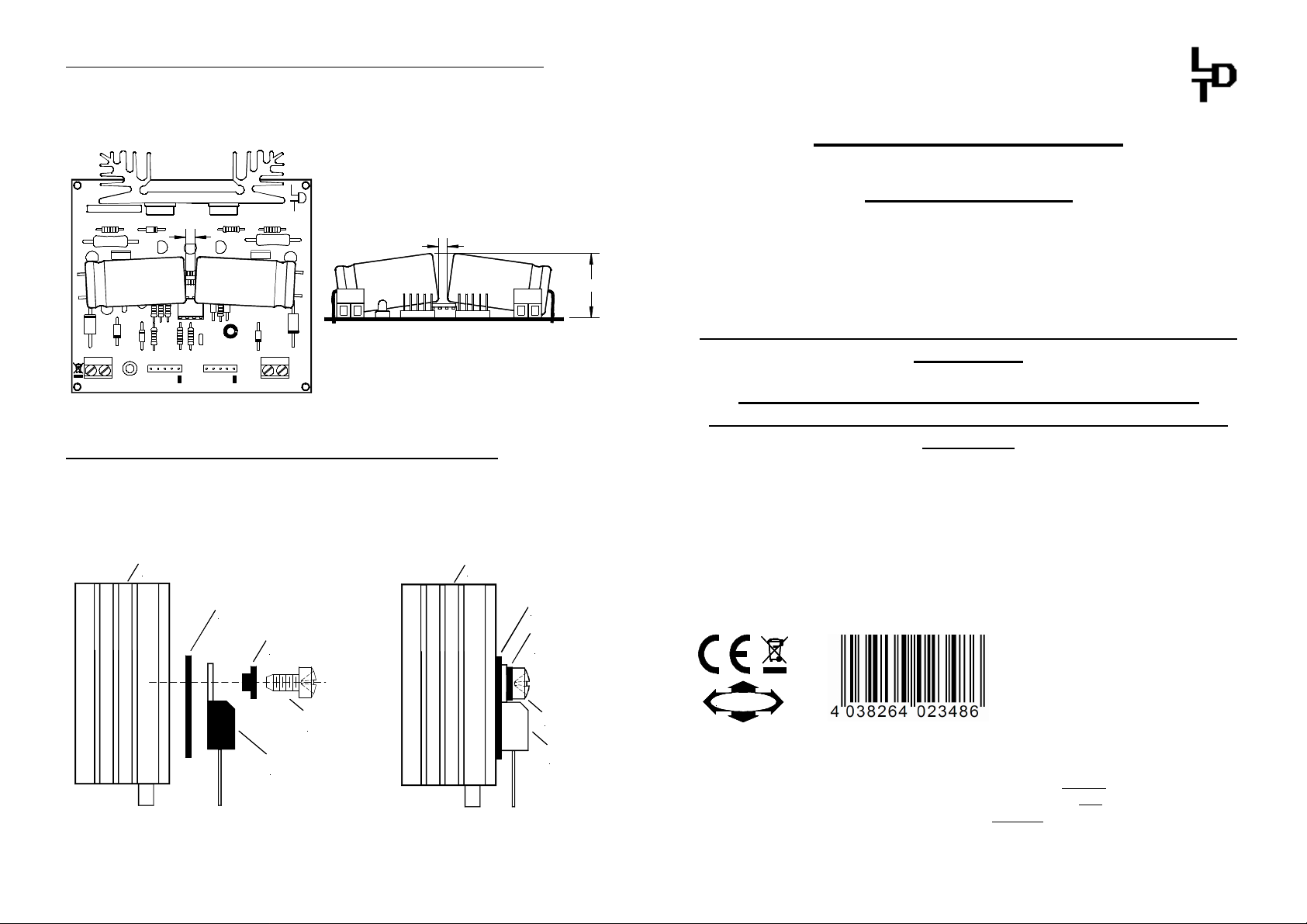
Assembly of the electrolytic capacitors C1 and C2:
The connection wires of capacitor C1 and C2 have to be bent by 90° before
assembly. The capacitors have to be soldered so that they are laying flat above the
components of the pc-board. The capacitors have to have a distance of 5mm. A
contact between the capacitors has to be prevented.
DB-2
Rev. 2.4
+
KL2
red brown
K J
ca. 5 mm
C1 C2
LED1
ST1 ST2
+
Littfinski DatenTechnik (LDT)
+
KL1
OUTIN
brown yellow
16...18V~
ca. 5 mm
C1 C2
max. 23 mm
Draft 1
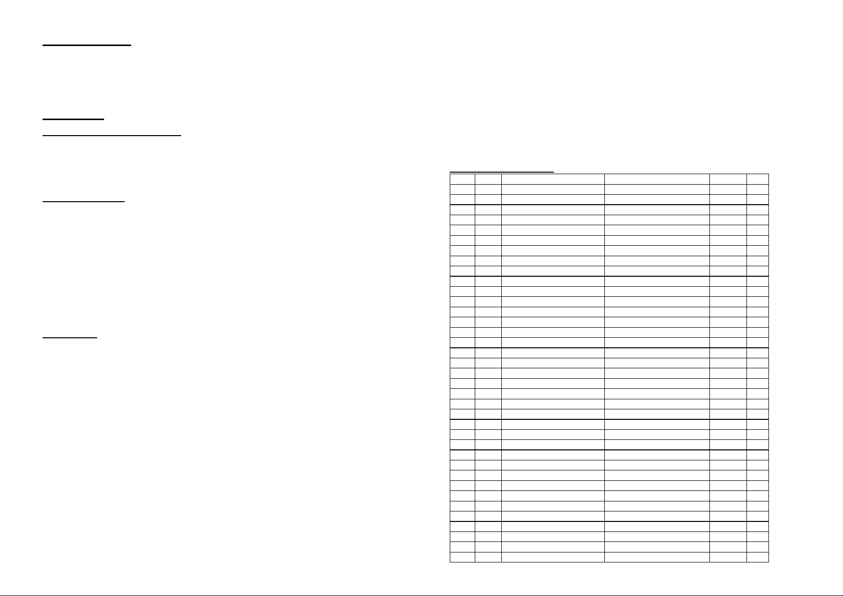
Assembly of the power transistors T1 and T2:
The power transistors T1 and T2 shall be assembled to the heat sink in accordance
to the drawing by using the insulator, isolating bushing and screw. Then insert the
complete pre-assembly into the bores of the pc-board and solder them.
Kühlkörper
heat sink
Isolator
insulator
Isolierbuchse
isolating bushing
Schraube
screw
Transistor
transistor
Draft 2 Draft 3
Kühlkörper
heat sink
Isolator
insulator
Isolierbuchse
isolating bushing
Schraube
screw
Transistor
transistor
Littfinski DatenTechnik (LDT)
Assembly Instruction
DigitalBooster DB-2
from the Digital-Professional-Series !
DB-2-B Part-No.: 080061
The DigitalBooster DB-2 is a short-circuit-proofed power
amplifier (booster) for digital model railway layouts.
Maximal power output: 2.5A.
The DB-2 amplifies the data formats Märklin-Motorola, mfx®,
M4 and DCC
The DB-2 can be directly operated on several digital
command stations by use of the attached 5-poles booster-
⇒ Control Unit (6021)
⇒ Central Station 1 and 2 (CS1 and CS2)
⇒ Intellibox, EasyControl, ECoS, DiCoStation, KeyCommander
⇒ TWIN-CENTER
This product is not a toy! Not suitable for children under 14 years of age! The kit contains small parts, which
should be kept away from children under 3! Improper use will imply danger of injuring due to sharp edges and
tips! Please store this instruction carefully.
Multi-Digital
CE Part-No.:
49 91 39
>> kit <<
bus cable:
Made in Europe by
Littfinski DatenTechnik (LDT)
Kleiner Ring 9
D-25492 Heist/Germany
Phone: 0049 4122 / 977 381
Fax: 0049 4122 / 977 382
Internet: http://www.ldt-infocenter.com
Subject to technical changes and errors. 05/2013 by LDT
Märklin and Motorola are registered trade marks.
Introduction:
Pos.
Qty.
Component
Remarks
Ref.
Done
You have purchased a kit for your model railway supplied within the assortment of
Littfinski DatenTechnik (LDT). These kits are of high quality and easy to assemble.
We are wishing you having a good time for assembling and application of this
product!
General:
Tools required for the assembly
Please assure that the following tools are available:
• a small side cutter
• a mini soldering iron with a small tip
• solder tin (if possible 0,5mm diameter)
Safety Instructions
• All electrical and electronic components included in this kit shall be used on low
voltage only by using a tested and approved voltage transducer (transformer). All
components are sensitive to heat. During soldering the heat shall be applied for a
very short period only.
• The soldering iron develops a heat up to 400°C. Please keep continual attention to
this tool. Keep sufficient distance to combustible material. Use a heat resistant pad
for this work.
• This kit consist of small parts which can possibly be swallowed from children.
Children (especially under 3 years) shall not participate on the assembly without
supervision.
Set-Up:
For the board assembly please follow exact the sequence of the below assembly list.
Cross each line off as done after completing the insertion and the soldering of the
respective part.
For the diodes please keep special attention the correct polarity (marked line for the
cathode).
With reason to different makes of electrolytic capacitors you will find different
markings of the polarity. Some are marked with "+" and some are marked with "-".
Each capacitor has to be assembled to the board that the marking on the capacitor is
in correspondence with the marking on the pc-board. The connection wires of
capacitor C1 and C2 have to be bent by 90° before assembly. The capacitors have to
be soldered so that they are laying flat above the components of the pc-board (shown
at draft 1). The capacitors have to have a distance of 5mm. A contact between the
capacitors has to be prevented.
For tantalum capacitors please attend to the connection wire marked "+". This wire
has to correspond to the printed mark on the pc-board.
Light emitting diodes have to be assembled that the long wire of the diode
corresponds to the mark "+" on the pc-board. Before assembly please slip the
distance spacer onto the connection wires.
At the transistor BC 5XX and the voltage regulator IC1 the flattened side has to be
observed.
The transistors T3 and T4 have to be assembled that way that the printed lettering
shows to the middle of the pc-board.
The power transistors T1 and T2 shall be assembled to the heat sink in accordance
to the drawing by using the insulator, isolating bushing and screw. Then insert the
complete pre-assembly into the bores of the pc-board and solder them (as shown in
draft 2 and 3).
Integrated circuits LM393 are either marked with a half round notch on one end or a
printed point for the correct mounting position. Push the IC`s into the correct socket
assuring that the notch or the printed point is corresponding to the half-rounded
marking on the pc-board.
Assembly List:
1 1 Printed circuit board
2 2 Resistors 0,18 Ohm marking:"R18" R1, R2
3 2 Resistors 2,2 Ohm red-red-black-silver R3, R4
4 2 Resistors 47 Ohm yellow-violet-black-gold R5, R6
5 2 Resistors 1KOhm brown-black-black-brown R7, R8
6 1 Resistor 2,7KOhm red-violet-black-brown R9
7 1 Resistor 3,3KOhm orange-orange-black-brown R10
8 2 Resistors 47KOhm yellow-violet-black-red R11, R12
9 1 Resistor 5,6KOhm green-blue-black-brown R13
10 4 Resistors 10KOhm brown-black-black-red R14...R17
11 1 Resistor 22KOhm red-red-black-red R18
12 1 Resistor 68KOhm blue-gray-black-red R19
13 2 Diodes BY251 attend to the polarity! D1, D2
14 1 Diodes 1N4003 attend to the polarity! D3
15 10 Diodes 1N4148 attend to the polarity! D4...D13
16 1 IC-Socket 8poles IC2
17 2 Capacitors 100nF 100nF = 104 C5, C6
18 1 Tantalum cap. 1uF/35V attend to the polarity! C4
19 1 Electrolytic cap. 47uF/50V attend to the polarity! C3
20 1 LED plus distance spacer attend to the polarity! LED1
21 1 78L06 attend to the polarity! IC1
22 2 Transistors BC 547 attend to the polarity! T5, T6
23 3 Transistors BC 557 attend to the polarity! T7...T9
24 1 Transistor BD139 attend to the polarity! T3
25 1 Transistor BD140 attend to the polarity! T4
26 2 Cross recess screws M3x6 for assembly of T1 and T2
27 2 Silicone insulators for assembly of T1 and T2
28 2 Isolating bushings for assembly of T1 and T2
29 1 Heat sink for assembly of T1 and T2
30 1 Transistor BD243 assembly on heat sink T1
31 1 Transistor BD244 assembly on heat sink T2
32 2 Pin plugs 5poles ST1, ST2
33 2 Clamps 2poles KL1, KL2
34 1 IC: LM393 attend to the polarity! IC2
35 2 Electrolytic cap.4700uF/35V attend to the polarity! C1, C2
36 1 Multi-Fuse MF1
37 Final control