

Page 1
L
Operating Instruction
ittfinski DatenTechnik (
LDT
)
Light-Signal Decoder
for light-signals with LED
from the Digital-Professional-Series !
LS-DEC-SBB-F
Suitable for the digital systems:
Märklin-Motorola and DCC
For digital control of:
⇒ up to two Swiss SBB signals with 5 or 7 lamps
⇒ signals can be switched together or independent
⇒ for LED-signals with common anode or cathode
Realistic operation of the signal aspects by implemented
dimming function and dark phase between the signal
aspects.
This product is not a toy! Not suitable for children under 14 years of age!
The kit contains small parts, which should be kept away from children under 3!
Improper use will imply danger of injuring due to sharp edges and tips! Please store
this instruction carefully.
44 40 52
Label:
white point
Multi-Digital
or SBB
Introduction/Safety instruction:
You have purchased the Light-Signal Decoder LS-DEC-SBB for your
model railway as a kit or as finished module.
The LS-DEC is a high quality product that is supplied within the
Professional-Series
We are wishing you having a good time using this product.
The Light-Signal Decoder LS-DEC of the
can be easily operated on your digital model railway.
By using a connector plug bridge you can choose if you want to
connect the decoder to a Märklin-Motorola system or to a digital system
with DCC standard.
The finished module comes with 24 month warranty.
• Please read the following instructions carefully. Warranty will expire
due to damages caused by disregarding the operating instructions.
LDT will also not be liable for any consequential damages caused by
improper use or installation.
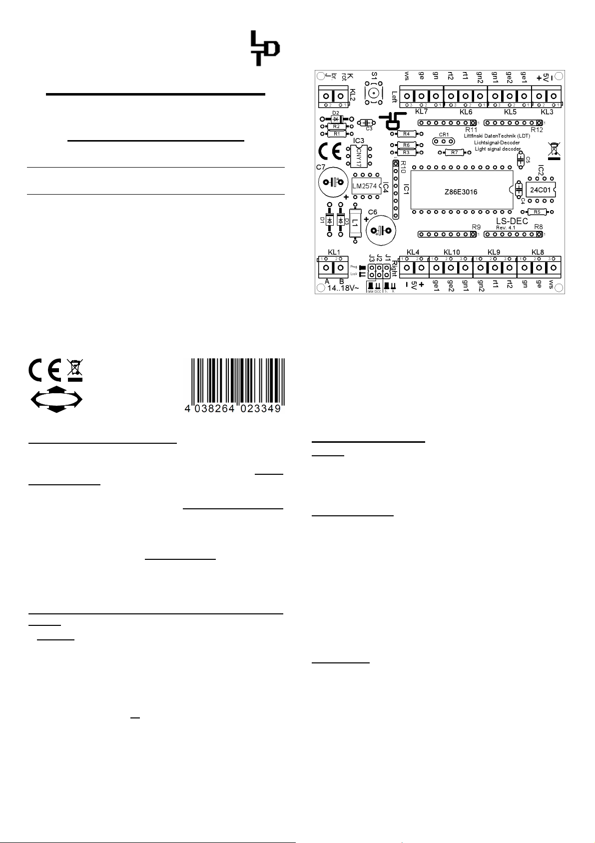
Connecting the decoder to your digital model railway
layout:
• Attention: Before starting the installation-work switch off the
layout voltage supply (switch-off the transformers or disconnect
the main supply).
The Light-Signal Decoder LS-DEC is suitable for the DCC data format
as used e.g. by Lenz-Digital Plus, Roco-Digital (switching via
Keyboard or multiMAUS only; switching via Lokmaus 2® and R3® is
not possible), Zimo, LGB-Digital, Intellibox, TWIN-CENTER,
DiCoStation, ECoS, EasyControl, KeyCom-DC and Arnold-Digital /
Märklin-Digital= whenever no connector plug bridge is inserted in
position J2.
The decoder is suitable for Märklin-Digital~ / Märklin Systems or
Märklin-Motorola (e.g. Control-Unit, Central Station, Intellibox,
DiCoStation, ECoS, EasyControl, KeyCom-MM) if you insert a
connector plug bridge on J2.
The decoder receives the digital information via the clamp KL2.
Connect the clamp with a rail or even better connect the
digital main ring supply assuring the supply of digital information free from
any interference.
>> finished module <<
CE Part-No.:
of Littfinski DatenTechnik (LDT).
Part-No.:
513012
Digital-Professional-Series
clamp to an own
Digital-
Please attend to the marking on clamp KL2. The colors 'red' and 'brown'
next to the clamp are usually used by Märklin-Motorola systems (e.g.
Märklin-Digital~ / Märklin Systems / Intellibox DiCoStation /
EasyControl)
Lenz-Digital systems are using the letters 'J' and 'K'.
.
In case you assemble the decoder to an Arnold-Digital (old) or Märklin-
Digital= system, you have to connect 'black' to 'K' and 'red' to 'J'.
The decoder receives the power supply via the two poles clamp KL1.
The voltage shall be in a range of 14...18V~ (alternate voltage output of
a model rail road transformer).
If you do not want to supply voltage separately from a transformer to
the LS-DEC decoder you can shorten the clamp KL1 and KL2 with two
wires. In this case the decoder will get the power supply completely from
the digital network.
Connecting the signals:
General:
Up to 2 signals with 5 or 7 lamps can be connected to the Light-Signal
Decoder LS-DEC. One signals per clamp block. The build up of the two
clamps is identical. The following description refers mainly to one clamp
only. As you can see on the identical marking the description is also valid
for the second clamp.
Common connection:
All LED-signals of any manufacturer are designed in accordance to the
same principle. One wire of all light emitting diodes of a signal will be
generally connected to a common wire. Depending if all anodes or all
cathodes are connected together the signals will be called as common
anodes- respectively common cathodes-signal.
If you use signals with common anodes (e.g. supplied from Viessmann
or alphamodell) you have to clamp this wire to the connection marked '+'.
In addition you shall not insert the connection plug bridge in J1 in this
case.
If you use signals with common cathodes you have to clamp this wire
to the connection marked '-'. In addition you shall insert the connection
plug bridge in J1 in this case.
The second connection of each light diode is separated and mostly color
marked at the end and contains a series resistor.
Series resistor:
Light emitting diodes have always to be operated with a suitable
series resistor to prevent that they will be destroyed. For this prevention
all outputs have already a series resistor of 330 Ohm integrated on
the printed circuit board of the Light-Signal Decoder LS-DEC. Is there
no further external resistor the diode-current will be about 10 mA.
This provides sufficient brightness.
For assigning the single cables of the light diodes to the correct
clamp connection please attend to the below signal images. The
marks next to signal light diodes are not corresponding to the actual
light color but to the marking of the connection at the Light-Signal
Decoder LS-DEC.
If you do not know the correct allocation of the single wires to the light
emitting diodes you can test the function by connecting the wires to
clamp RT1 or RT2. These outputs are active because the decoder
switches all signals to red after switching on.
Page 2
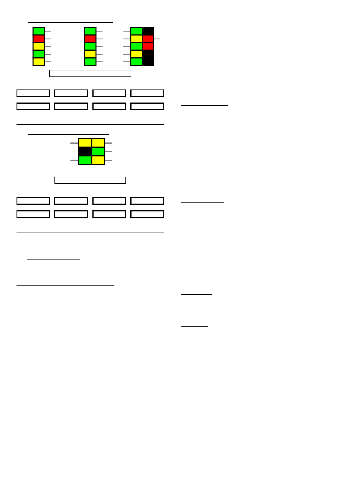
1. Home signal with 5 or 7 lamps:
train stop 40km/h 65km/h
round/red/- round/red/- round/red/- round/red/-
straight/green/+ straight/green/+ straight/green/+ straight/green/+
proceed 95km/h 40km/h
2. Advance signal with 5 lamps:
GN1
RT1
GE1
GN2
GE
home signal with 5 or 7 lamps
H 2 3
1 2 3 4
1 5 6
RT2 oder GN2
GN1
RT1
GN2
GE1
WS
GN1
GE
GN2
GE1
WS
RT1GE1 oder GE2
GN1 oder GN
WS
RT1
There are three wire bridges required. Connect GN1 with GN, RT2 with
GN2 and GE1 with GE2.
advance signal with 5 lamps
H 2 3
train stop 40km/h 65kmh (dark switch)
round/red/- round/red/- round/red/- round/red/-
1 2 3 4
straight/green/+ straight/green/+ straight/green/+ straight/green/+
proceed 95km/h 40km/h
1 5 6
Further sample connections are available at the internet on our WebSite (www.ldt-infocenter.com) at the section “Sample Connections”.
Additionally you can find detailed information about the Light-Signal
Decoder LS-DEC-SBB at our Web site within the section “Digital-
Compendium”.
Programming the decoder address:
• The jumper J3 has to be inserted for the programming of the decoder
addresses.
• Switch on the power supply of your model rail way.
• Activate the programming key S1.
• At least two light emitting diodes on a signal connected to the left
clamp block (on this decoder side is the programming key S1) will
be automatically switched over every 1.5 seconds in a flashing
mode. This indicates that the decoder is in the programming mode.
• The decoder addresses for magnet accessories also to be used for
switching the signal-aspects are combined into groups of four. The
address 1 to 4 build the first group. The address 5 to 8 build the
second group etc. In accordance to the operation mode 4 or 8
addresses will be assigned to the decoder. At the mode "single
function" both signals connected to the Light-Signal Decoder can
be operated absolute independent. The decoder requires for the
operation mode 8 addresses (4 addresses for each clamp bar).
At the "master/slave-function" both signals will be switched with
one command. Therefore will it be possible e.g. to switch home- and
advance signals together. In this operation mode the Light-Signal
Decoder requires only 4 addresses.
The operation mode has to be entered together with the decoder
address. If you activate during address-programming a key of the
required group of four which would switch a turnout straight or a
signal to green the decoder will go into the "single function mode".
If you activate a key which would switch a turnout round or switch a
signal to red you choose therefore the "function master/slave".
• If the decoder has recognized the assignment correctly the
connected light emitting diode will flash a little faster. Afterwards
the flashing slows down to the initial 1.5 seconds again.
In case the decoder will not recognize the address it could be that the
two digital information connections (clamp2) are wrong connected.
For testing this, switch off the power supply, exchange the connection
on KL2 and start addressing again.
• Press now the programming key S1 again. Have you chosen the
operation mode "master/slave function" the decoder will leave the
programming mode because the programming of the group of four
has been completed. All signals will be automatically switched to
stop. The "master/slave function" has now been completed.
Have you chosen the operation mode "single function" you have
assigned the address group of the left clamp bar with the first
programming step. Therefore two light emitting diodes will flash
at the signal connected to the right clamp bar. Now activate any
key of the address group assigned for this signal. The decoder will
confirm the programming with a faster flashing.
Then press the programming key S1 again. The programming for
the "single function" has now been completed. Both connected
signals will switched to STOP by the decoder.
Signal switching:
The opposite sample connections show how the fourfold addressgroup can be set by use of 8 keys of the push button panel for setting
the turnouts or signals. Between each pair of keys are e.g. the addresses
1 to 4. The two keys red and green for each address are assigned to
the turnout position round or straight respectively the corresponding
signal aspect which is indicated above or below key.
The actual address section is related to which fourfold address-group
has been selected during the programming.
If you use a remote control LH100 of Company Lenz Elektronik then
red will be the minus key and green the plus key.
If you have connected an advance- and an exit-signal to one of the two
clamp bars (as shown at the first sample) you can switch with the address
1 and the key green the exit signal to proceed (1).
The light emitting diode marked with GN will now indicate this at the
signal.
Dark switching:
In case a home- and an advance-signal are on one common signal
post the advance-signal can remain dark if the home-signal indicates
H or 6.
To activate the dark-switching-mode switch the home signal to H or 6.
If you press now the key 4 'red' you can switch the advance-signal-aspect
to 'on' respectively to 'off' with each keystroke. If the advance-signal is in
'off' position the dark-switching mode is activated.
The Light-Signal Decoder stores this mode permanently as well as
the programmed addresses. All programmed modes can be changed
at any time. The dark switching can be activated or deactivated only if the
jumper J3 has been inserted.
Advance signal aspects received during the signal has been switched to
dark will be indicated whenever the exit signal has been switched to 1, 2,
3 or 5.
Accessory:
For easy assembly of the printed circuit board below your model rail road
layout base plate we offer a set of assembly material under the order
identification: MON-SET. Under LDT-01 you can purchase a low priced
durable suitable case for the LS-DEC.
Attention:
The Light-Signal Decoder LS-DEC switches the signal aspect not just
quickly on and off but is dimming the light emitting diodes realistic up and
down. Even between the signal aspects a short off-phase is provided.
Further digital commands received during this switch-over-time of about
0.4 seconds will not be taken up from the decoder. Please take care that
the switching-commands are not in a to fast sequence. The impression
is absolutely realistic if the switching is considerable slow.
If the jumper J3 will be removed after programming of the decoder
addresses and after adjusting the dark switching mode the memory
storage of the Light-Signal Decoder LS-DEC will be protected against
any alteration.
Made in Europe by
Littfinski DatenTechnik (LDT)
Bühler electronic GmbH
Ulmenstraße 43
15370 Fredersdorf / Germany
Phone: +49 (0) 33439 / 867-0
Subject to technical changes and errors. 05/2019 by LDT
Internet: www.ldt-infocenter.com
Märklin and Motorola are registered trade marks.
 Loading...