

Page 1
Littfinski DatenTechnik (LDT)
Multi-Digital
Light emitting diodes have to be assembled that the long wire of the diode
corresponds to the mark "+" of the pc-board. Before assembly please slip the distance
spacer onto the connection wires.
The resistor-network RN1 is marked at one end for the assembly position with
“...103...” and additionally with a printed circle or a square. Assemble this component
that way that the marking corresponds with the marking at the first bore of the pcboard. Additionally is the first bore marked with “1”.
Integrated circuits (IC`s) are either marked with a half round notch on one end or a
printed point for the correct mounting position. Push the IC`s into the correct socket
assuring that the notch or the printed point is corresponding to the half-rounded
marking on the pc-board. The 4-poles integrated circuit LTV814 (IC6) shall be
soldered directly onto the pc-board.
Please attend to the sensitivity of the ICs to electrostatic discharge, which will cause
immediate damage of the IC. Before touching those components please discharge
yourself by contacting an earthed metal (e.g. earthed radiator) or work with an
electrostatic safety pad.
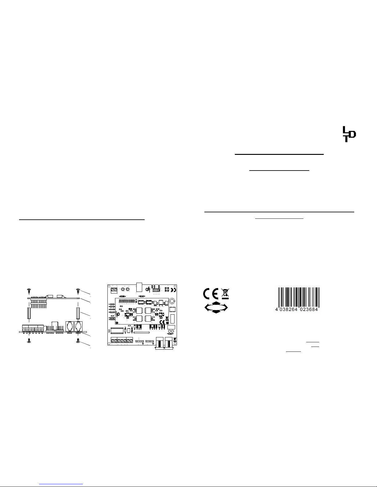
Assembly of the DB4-Power PC-Board:
After completing the DB-4 basic pc-board you can assemble the SMD-pre-assembled
and tested DB4-Power PC-Board.
Firstly please tighten the two distance spacer to the basic pc-board with two of the four
cross section screws.
Apply now the DB4-Power PC-Board into the socket bar BU4 of the basic pc-board.
Pay attention that there is no offset of the DB4-Power PC-Board to the socket. The
DB4-Power PC-Board is in correct position at the socket bar BU4 of the basic pc
board if you can screw the DB-Power PC Board to the distance bolts.
The following picture 1 show the assembly procedure from the side view and the
picture 2 show the assembled DB4-Power-PC Board onto the basic PC-Board with
sight from the top.
Schraube
screw
DB-4-Basis
Distanzbolzen
distance spacer
DB4-Power
Schraube
screw
DB4-Power
Rev. 1.4
Littfinski DatenTechnik (LDT)
IC4 IC5
ST1
C3
R6
R5
D7
D5
C11
R1
D3
D2
IC1
R3
C4
C7
C8
C1 C2
C10
IC3
C9
D6
C6
R2
IC2
D1
D4
R4
C5
T1
T3
T4
T2
1 3 5 7 9 11 131517 19
2 4 6 8
10 12 14 16 18 20
JP5
2,5
4,5
ShortReport
RailCom
GoAuto
ONOFF
JP4
JP3
JP2
JP1
MMDCC
BU1
DB-4
Rev. 1.4
JK
Littfinski DatenTechnik (LDT)
+
STOPGO
LED2LED1
red brown
S1
+
KL3KL4KL2
STOP/GO
EDC
BU2
BU3
ST2ST1
IN OUT
Feedback
A
T
KL1
Picture 1 Picture 2
DigitalBooster DB-4
from the Digital-Professional-Series !
DB-4-B Part-No.: 080071
>> kit <<
The DigitalBooster DB-4 is a short-circuit-proofed power
amplifier (booster) for digital model railway layouts.
It provides a maximum digital current of 2,5 or 4,5 Ampere.
The DB-4 amplifies the digital formats of Märklin-Motorola,
mfx®, M4 and DCC.
The DB-4 can operate on several digital command stations
by using the 5-poles booster bus, the CDE-booster bus or
the Roco-booster bus.
The DigitalBooster DB-4 receives the power supply not from
a classical model railway transformer but from the switched
mode mains power supply DB-4 PowerSupply. On this unit is
the stabilized digital track voltage adjustable between 15 and
24 Volt, suitable for all track gauges.
This product is not a toy! Not suitable for children under 14 years. Improper use will imply danger or injuries due
to sharp edges and tips! Please store this instruction carefully.
CE Part-No.:
1370364
Made in Europe by
Littfinski DatenTechnik (LDT)
Kleiner Ring 9
D-25492 Heist/Germany
Phone: 0049 4122 / 977 381
Fax: 0049 4122 / 977 382
Internet: http://www.ldt-infocenter.com
Subject to technical changes and errors. 07/2015 by LDT
Märklin, Motorola and mfx are registered trademarks.
Assembly Instruction
Page 2
Introduction:
You have purchased a kit for your model railway supplied within the assortment of
Littfinski DatenTechnik (LDT). These kits are of high quality and easy to assemble.
We are wishing you having a good time for assembling and application of this
product!
General:
Tools required for the assembly
Please assure that the following tools are available:
• a small side cutter
• a mini soldering iron with a small tip
• solder tin (if possible 0,5mm diameter)
Safety Instructions
• All electrical and electronic components included in this kit shall be used on low
voltage only by using a tested and approved voltage transducer (transformer). All
components are sensitive to heat. During soldering the heat shall be applied for a
very short period only.
• The soldering iron develops a heat up to 400°C. Please keep continual attention to
this tool. Keep sufficient distance to combustible material. Use a heat resistant pad
for this work.
• This kit contains small parts which can possibly be swallowed from children.
Children (especially under 3 years) shall not participate on the assembly without
supervision.
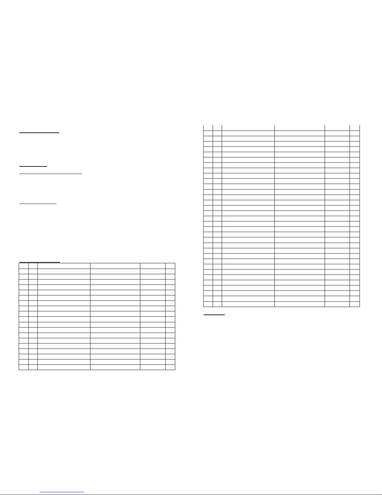
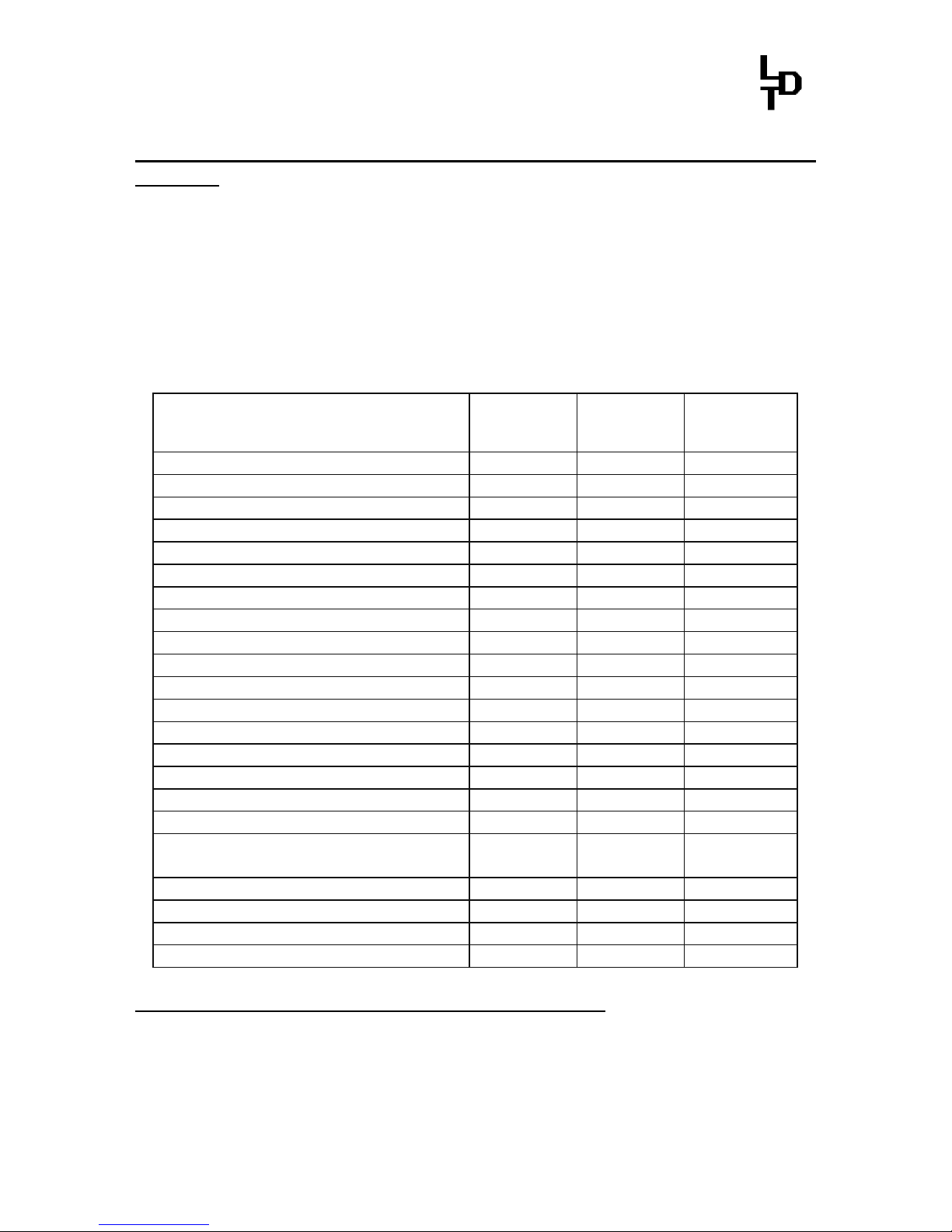
Assembly List:
Pos. Qty. Components Remarks Ref. Done
1 1 Printed circuit board DB-4 Rev. 1.4
2 2 Resistors 0,1 Ohm Marked: "R10" R1, R2
3 1 Resistor 10 Ohm brown-black-black-gold R3
4 1 Resistor 100 Ohm brown-black-black-black R4
5 1 Resistor 180 Ohm brown-gray-black-black R5
6 2 Resistors 220 Ohm red-red-black-black R6, R7
7 1 Resistor 330 Ohm orange-orange-black-black R8
8 1 Resistor 470 Ohm yellow-violet-black-black R9
9 1 Resistor 1 KOhm brown-black-black-brown R10
10 1 Resistor 2,2 KOhm red-red-black-brown R12
11 2 Resistors 3,3 KOhm orange -orange -black-brown R13, R14
12 2 Resistors 4,7 KOhm yellow-violet-black-brown R15, R16
13 4 Resistors 10 KOhm brown-black-black -red R11,R18...R20
14 1 Resistor 12 KOhm brown-red-black-red R21
15 1 Resistor 27 KOhm red-violet-black-red R22
16 3 Resistors 47 KOhm yellow-violet-black-red R17,R23,R24
17 1 Resistor 1 MOhm brown-black -black-yellow R25
18 1 Network 5*10 KOhm attend to polarity! RN1
19 10 Diodes 1N4003 attend to polarity! D1...4, D6...11
20 3 Diodes 1N5819 attend to polarity! D5, D12, D13
21 1 Z-Diode BZX ... 5V1 attend to polarity! D14
22 1 Z-Diode BZX ... 30V attend to polarity! D15
23 1 IC-socket 28poles attend to polarity marking! IC1
24 3 IC-sockets 8poles attend to polarity marking! IC2, 3, 5
25 1 IC-socket 16poles attend to polarity marking! IC7
26 1 IC: LTV814 attend to polarity! IC6
27 1 DC-DC Converter attend to polarity! IC4
28 1 Resonator 8MHz CR1
29 5 Capacitor 100nF 100nF = 104 C1...C5
30 1 Tantalum cap. 1uF/35V 1uF = 105; attend to polarity! C6
31 3 Tantalum cap. 10uF/10V 10uF = 106; attend to polarity! C7...C9
32 4 Electrolytic cap. 470uF/35V attend to polarity! C10...C13
33 1 Storage choke L1
34 1 DC-socket BU1
35 2 Sockets 4poles BU2, BU3
36 1 Socket bar 2x10poles BU4
37 1 Pin bar 2x5poles JP1 ... JP5
38 5 Jumpers set on pin bar 2x5poles JP1 ... JP5
39 2 Pin bars 5poles ST1, ST2
40 1 Push button S1
41 1 LED green plus distance sleeve attend to polarity! LED1
42 1 LED red plus distance sleeve attend to polarity! LED2
43 1 Clamp 2poles KL1
44 3 Clamps 2poles and 3poles build block prior to assembly KL2 ... KL4
45 1 IC: ATMEGA168-20 attend to polarity! IC1
46 1 IC: LM2574HVN-5 attend to polarity! IC2
47 1 IC: LM393 attend to polarity! IC3
48 1 IC: HCPL2631 attend to polarity! IC5
49 1 IC: LTV847 attend to polarity! IC7
50 4 Cross headed screws M3x6 for assembly "DB4-Power"
51 2 Distance spacer 18mm for assembly "DB4-Power"
52 1 DB4-Power assembly acc. instruction
53 final control
Set-Up:
For the board assembly please follow exact the sequence of the above assembly list.
Cross each line off as done after completing the insertion and the soldering of the
respective part.
For the diodes please keep special attention the correct polarity (marked line for the
cathode).
With reason to different makes of electrolytic capacitors you will find different
markings of the polarity. Some are marked with "+" and some are marked with "-".
Each capacitor has to be assembled to the board that the marking on the capacitor is
in correspondence with the marking on the pc-board.
For tantalum capacitors please attend to the connection wire marked "+". This wire
has to correspond to the printed mark on the pc-board.
Page 3
Littfinski DatenTechnik (LDT)
Kleiner Ring 9 • D-25492 Heist/Germany • Phone: 0049 4122 / 977 381 • Fax: 0049 4122 / 977 382
Multi-Digital
Manual
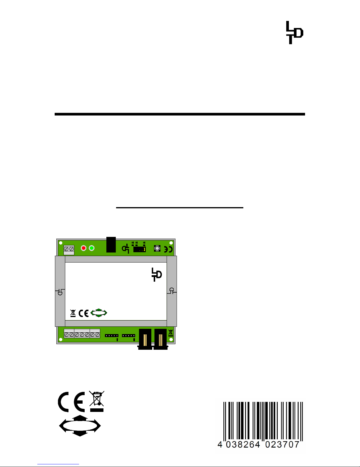
DigitalBooster DB-4
The DigitalBooster DB-4 is a short-circuit protected
Power-Amplifier (Booster) for digital Model Railway
Layouts from the Digital-Professional-Series!
The DB-4 amplifies the digital formats of Märklin-
Motorola, mfx®, M4 and DCC.
DB-4-G Part-No.: 080073
>> finished module in a case <<
BU1
+
S1
DCCMM
JP1
JP2
JP3
JP4
OFFON
Auto Go
RailCom
ShortReport
red brown
LED1 LED2
GO STOP
+
Littfinski DatenTechnik (LDT)
KL1
K J
4,52,5
JP5
OUTIN
ST1 ST2
Rev. 1.4
DB-4
BU3
BU2
C D E
STOP/GO
KL2 KL4 KL3
Feedback
A
T
2,5 / 4,5 Ampere Booster für die Digitalformate MärklinMotorola, mfx®, M4 und DCC.
2,5 / 4,5 ampere booster for Märklin-Motorola, mfx®, M4
and DCC.
DB-4
DigitalBooster
Multi-Digital
L
ittfinski DatenTechnik (
LDT
)
D-25492 Heist
www.ldt-infocenter.com
Digital-Profi werden!
The DigitalBooster DB-
4 provides a
maximum digital current of 2,5 or 4,5
Ampere and amplifies the digital
formats of Märklin-Motorola, mfx
®
, M4
and DCC.
The DB-
4 can operate with several
digital command stations by using the
5-
poles booster bus, the CDE booster
bus or the Roco-booster bus.
The DigitalBooster DB-4 receives the
power supply not from a classical
model railway transformer but from the
switched mode mains power supply
DB-4 PowerSupply. On this unit is the
stabilized digital track voltage
adjustable between 15 and 24 Volt,
suitable for all track gauges.
This product is not a toy! Not suitable for children under 14 years. Improper use will imply danger or injuries due to
sharp edges and tips! Please store this instruction carefully.
CE Part-No.:
1370365
Page 4

DigitalBooster DB-4 – Manual
- 1 -
Content: Page
1. Preface / Safety Instruction 2
2. DB-4 connection to the digital command station or to other
boosters 3
2.1. DB-4 connection via the 5-poles Boosterbus 3
2.2. DB-4 connection via the CDE-Boosterbus 5
2.3. DB-4 connection via the Roco-Boosterbus 5
3. DB-4 connection to the Switched Mode Mains Power
Supply DB-4 PowerSupply 6
4. DB-4 connection to an Own Track Section 6
4.1. 3-conductor Track System 7
4.2. 2-conductor Track System 9
5. Booster in Operation 10
6. Adjusting Operation Modes with Jumper 10
6.1. Select Maximum Digital Current to 2,5 or 4,5 Ampere 10
6.2. Select data format for WatchDog- and
On-/Off-switch function 11
6.3. RailCom®*-cutout Creation or Suppression 11
6.4. Short Circuit Report to the Command Station (Short Report) 11
6.5. Automatic Switch-On (Auto Go) 12
7. Addresses for WatchDog- and On-/Off switch function 12
7.1. Common Address Section 13
7.2. Own Address Sections 13
7.3. Programming address sections 14
8. WatchDog: Communication with the Model Railway Software 15
9. DB-4 switching On and Off via Accessory Address 16
10. DB-4 switching On and Off via external push button 16
11. Feedback Report for Booster-Management 18
12. Assembly Plan of the Basic PC-board 19
Page 5
DigitalBooster DB-4 – Manual
- 2 -
1. Preface / Safety Instruction:
You have purchased the DigitalBooster DB-4 within the assortment of Littfinski
DatenTechnik (LDT) for your model railway layout.
We are wishing you having a good time using this product!
The finished module in a case comes with 24 month warranty.
• Please read the following instructions carefully. Warranty will expire due to
damages caused by disregarding the operation instructions. LDT will not be
liable for any consequential damages caused by improper use or installation.
• You can download this manual from our Web-Site (www.ldt-infocenter.com) at the
section “Downloads“ as PDF-file with colored pictures. You can open the file with
the Acrobat Reader and you can make a print-out.
• Attention: Before starting the installation switch off the drive voltage by
disconnecting all model railway transformer from mains and/or switch off the
complete mains supply to the layout.
Vom DB-4-Power-Supply
From DB-4-Power-Supply
BU1
+
S1
DCCMM
JP1
JP2
JP3
JP4
OFFON
Auto Go
RailCom
ShortReport
red brown
LED1 LED2
GO STOP
+
Littfinski DatenTechnik (LDT)
KL1
K J
4,52,5
JP5
OUTIN
ST1 ST2
Rev. 1.4
DB-4
BU3
BU2
C D E
STOP/GO
KL2 KL4 KL3
Feedback
A
T
2,5 / 4,5 Ampere Booster für die Digitalformate MärklinMotorola, mfx®, M4 und DCC.
2,5 / 4,5 ampere booster for Märklin-Motorola, mfx®, M4
and DCC.
DB-4
DigitalBooster
Multi-Digital
L
ittfinski DatenTechnik (
LDT
)
D-25492 Heist
www.ldt-infocenter.com
Digital-Profi werden!
Rückmelden
feedback
PC mit USB-Schnittstelle
PC with USB interface
Littfinski DatenTechnik (LDT)
DiCoStation
Rev. 1.0
RIGHT MIDDLE LEFT
s88 Rückmeldebus
s88 feedback bus
14..18V~
br. gelb
ST5 ST4 ST3
Software by
Falkner
everytime up-to-date
USB
ST1
LED1 LED2
STOPGO
++
ST6 EXT-PORT
BOOSTER
ST2
Multi-Digital
Digital-Profi werden!
für die USB-Schnittstelle mit den Digitalformaten
DCC und Märklin-Motorola plus drei s88
Rückmeldestränge.
DiCoStation
DirectCommandStation
L
ittfinski DatenTechnik (
LDT
)
D-25492 Heist
www.ldt-infocenter.com
Fahren und Schalten
driving and switching
weiss
white
weiss
white
weiss
white
gelb
yellow
braun
brown
Vom Modellbahntrafo
From transformer
Bestellbezeichnung /
Order code: Kabel Booster 1m
Erzwagenzug
S-Bahn
ET 85
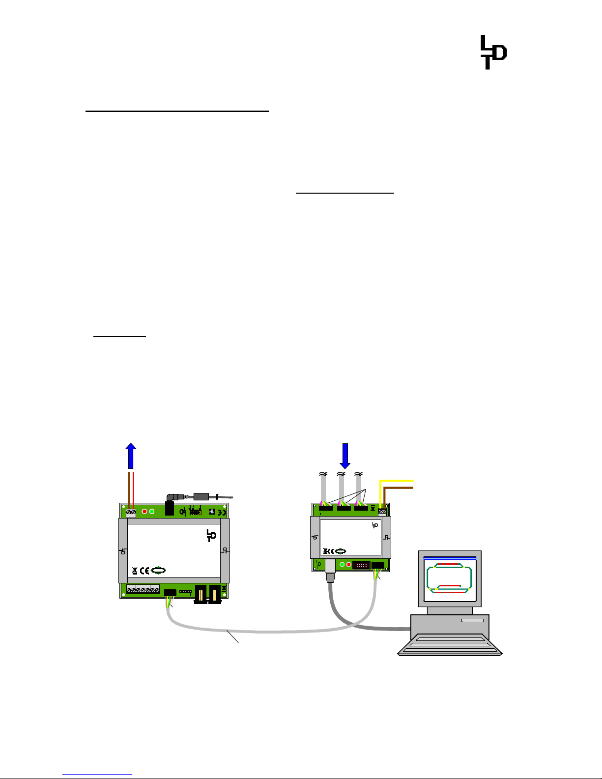
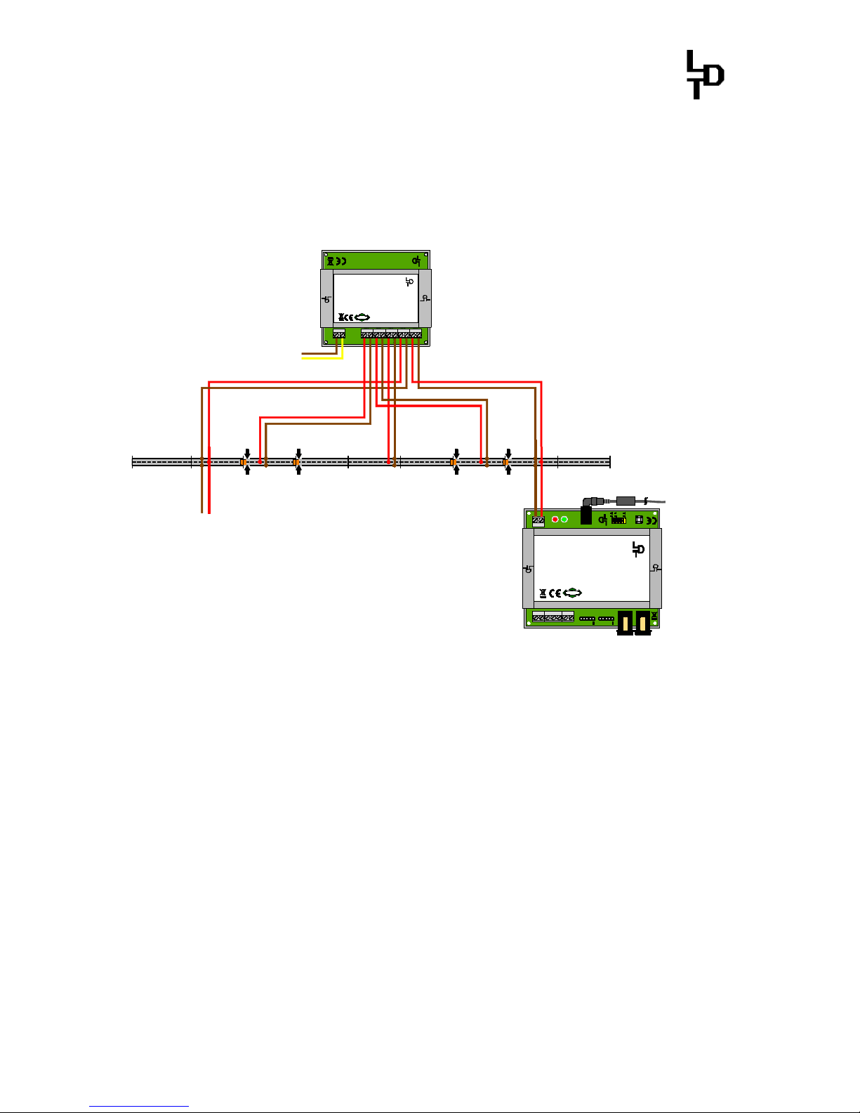
DigitalBooster DB-4 communication with the DiCoStation
Page 6
DigitalBooster DB-4 – Manual
- 3 -
2. DB-4 connection to the Digital-Command-Station or to other
Booster:
The galvanic separated boosterbus connections enables the application of the
DigitalBooster DB-4 in connection with several command stations by using the 5poles Boosterbus, the CDE-Boosterbus or the Roco-Boosterbus.
The DB-4 is no Booster-Adapter. A change of the bus-system is impossible. The
booster-bus used for the connection of the first DB-4 to the digital command
station has to be used furthermore.
The below table indicates the possible connections to the available command
station.
5-poles
Boosterbus
CDE-
Boosterbus
Roco-
Boosterbus
Control Unit X
Central Station 1 X X
Central Station 2 X
Mobile Station 2 with Track Box X
ECoS 1 (50 000) X X
ECoS 2 (50 200) X X
Intellibox 1 X X
IB-Basic X
IB-COM X
Intellibox 2 X X
EasyControl X X
DiCoStation X
KeyCommander X
TWIN-CENTER X X
Roco 10761 (multiMAUS) X
Roco 10764 (multiMAUS) X
Fleischmann 680801 (multiMAUS) X
Roco / Fleischmann
multiZENTRALEpro
X
Roco / Fleischmann z21 and Z21 X
Lenz Digital plus LZ100 X
Lenz Digital plus LZV200 X
Viessmann Commander X X
2.1. DB-4 connection via the 5-poles Boosterbus:
The DigitalBooster DB-4 can be connected by use of the 5-poles boosterbus cable
(order code: Kabel Booster 1m, Part-No.: 000123), to one of the command stations
as per above table or to other boosters (e.g. DB-4, DB-2, 6015, 6017, Power 2, Power
3). The first booster shall be always connected to the command station by use of a 5-
poles boosterbus cable. The second booster shall be connected to the first one and so
on.
Page 7
DigitalBooster DB-4 – Manual
- 4 -
Please connect a plug of the 5-poles boosterbus cable onto the command station or to
the previous booster. The connection of the plug is correct at the Control Unit,
Intellibox, TWIN-CENTER, Märklin Booster 6017, Power 2 and Power 3 if the
direction of the cable shows to the bottom. For the Märklin Booster 6015 is the
correct position of the Boosterbus-Cable showing to the top.
The second plug of the boosterbus cable has to be connected at the DigitalBooster
DB-4 to the pin bar ST1 with the marking “IN“.
Please attend that the white single wire of the 5-poles cable corresponds to the
white marking at the pin bar ST1.
The plug position of the 5-poles boosterbus cable is correct on the DigitalBooster
DB-4 if the twisted cable has a direction away from the booster.
If a following booster shall be connected with a 5-poles boosterbus cable to the
DigitalBooster DB-4 this has to be done via the pin bar ST2 (“OUT”).
BU1
+
S1
DCC
MM
JP1
JP2
JP3
JP4
OFFON
Auto Go
RailCom
ShortReport
red brown
LED1 LED2
GO STOP
+
Littfinski DatenTechnik (LDT)
KL1
K J
4,52,5
JP5
OUTIN
ST1 ST2
Rev. 1.4
DB-4
BU3
BU2
C D E
STOP/GO
KL2 KL4 KL3
Feedback
A
T
2,5 / 4,5 Ampere Booster für die Digitalformate MärklinMotorola, mfx®, M4 und DCC.
2,5 / 4,5 ampere booster for Märklin-Motorola, mfx®, M4
and DCC.
DB-4
DigitalBooster
Multi-Digital
L
ittfinski DatenTechnik (
LDT
)
D-25492 Heist
www.ldt-infocenter.com
Digital-Profi werden!
braun
brown
J
rot
red
K
Vom DB-4-PowerSupply 2
From DB-4-PowerSupply 2
Gleisbereich 2
Track section 2
weiss
white
BU1
+
S1
DCCMM
JP1
JP2
JP3
JP4
OFFON
Auto Go
RailCom
ShortReport
red brown
LED1 LED2
GO STOP
+
Littfinski DatenTechnik (LDT)
KL1
K J
4,52,5
JP5
OUTIN
ST1 ST2
Rev. 1.4
DB-4
BU3
BU2
C D E
STOP/GO
KL2 KL4 KL3
Feedback
A
T
2,5 / 4,5 Ampere Booster für die Digitalformate MärklinMotorola, mfx®, M4 und DCC.
2,5 / 4,5 ampere booster for Märklin-Motorola, mfx®, M4
and DCC.
DB-4
DigitalBooster
Multi-Digital
L
ittfinski DatenTechnik (
LDT
)
D-25492 Heist
www.ldt-infocenter.com
Digital-Profi werden!
braun
brown
J
rot
red
K
Vom DB-4-PowerSupply 1
From DB-4-PowerSupply 1
Gleisbereich 1
Track section 1
weiss
white
Bestellbezeichnung /
Order code: Kabel Booster 1m
Von Digitalzentrale
From command station
Zu weiteren Boostern
To further boosters
DigitalBooster DB-4 connection to the command station and between each other via the 5-poles
boosterbus.
Page 8
DigitalBooster DB-4 – Manual
- 5 -
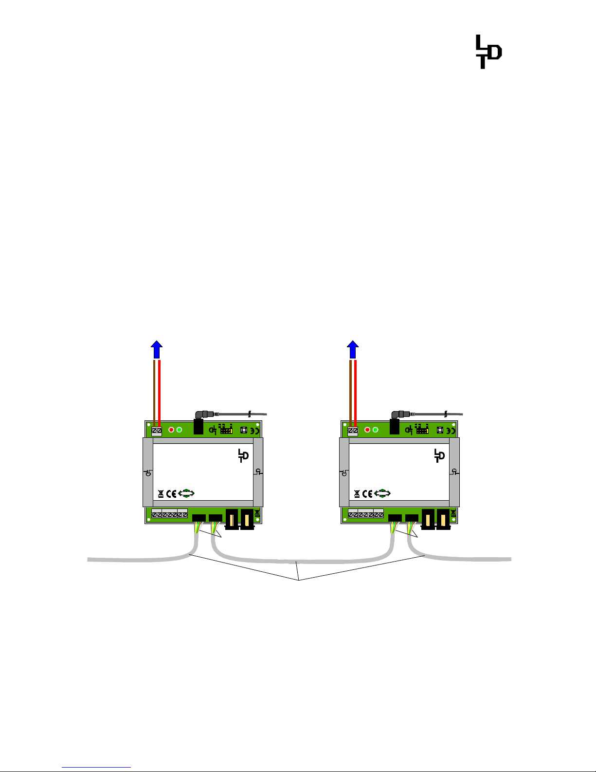
2.2. DB-4 connection via the CDE-Boosterbus:
If your Command Station contains a CDE-Boosterbus the connection to the
DigitalBoosters DB-4 can be realized with three cables. Connect the connection
wires C, D and E of the Command Station with the clamps C, D and E of the
following DigitalBooster DB-4.
BU1
+
S1
DCC
MM
JP1
JP2
JP3
JP4
OFFON
Auto Go
RailCom
ShortReport
red brown
LED1 LED2
GO STOP
+
Littfinski DatenTechnik (LDT)
KL1
K J
4,52,5
JP5
OUTIN
ST1 ST2
Rev. 1.4
DB-4
BU3
BU2
C D E
STOP/GO
KL2
KL4 KL3
Feedback
A
T
2,5 / 4,5 Ampere Booster für die Digitalformate MärklinMotorola, mfx®, M4 und DCC.
2,5 / 4,5 ampere booster for Märklin-Motorola, mfx®, M4
and DCC.
DB-4
DigitalBooster
Multi-Digital
L
ittfinski DatenTechnik (
LDT
)
D-25492 Heist
www.ldt-infocenter.com
Digital-Profi werden!
braun
brown
J
rot
red
K
Vom DB-4-PowerSupply 2
From DB-4-PowerSupply 2
Gleisbereich 2
Track section 2
BU1
+
S1
DCCMM
JP1
JP2
JP3
JP4
OFFON
Auto Go
RailCom
ShortReport
red brown
LED1 LED2
GO STOP
+
Littfinski DatenTechnik (LDT)
KL1
K J
4,52,5
JP5
OUTIN
ST1 ST2
Rev. 1.4
DB-4
BU3
BU2
C D E
STOP/GO
KL2
KL4 KL3
Feedback
A
T
2,5 / 4,5 Ampere Booster für die Digitalformate MärklinMotorola, mfx®, M4 und DCC.
2,5 / 4,5 ampere booster for Märklin-Motorola, mfx®, M4
and DCC.
DB-4
DigitalBooster
Multi-Digital
L
ittfinski DatenTechnik (
LDT
)
D-25492 Heist
www.ldt-infocenter.com
Digital-Profi werden!
braun
brown
J
rot
red
K
Vom DB-4-PowerSupply 1
From DB-4-PowerSupply 1
Gleisbereich 1
Track section 1
Von Digitalzentrale
From command station
Zu weiteren Boostern
To further boosters
C
D
E
C
D
E
Connecting the DigitalBooster DB-4 with the Command Station via CDE-Boosterbus and between
each other
2.3. DB-4 connection via the Roco-Boosterbus:
With the Roco Boosterbus-Cable (Order Code: Kabel Roco 1m, Part -No.: 000136),
is it possible to connect the DigitalBooster DB-4 with the multiMAUS,
multiZENTRALEpro or z21 and Z21 command stations according to the table or to
connect the DB-4 to a Roco Booster. The first booster has to be connected always to
the command station by using a Roco Boosterbus-Cable. The second booster has to
be connected to the first one etc.
Page 9

DigitalBooster DB-4 – Manual
- 6 -
BU1
+
S1
DCCMM
JP1
JP2
JP3
JP4
OFF
ON
Auto Go
RailCom
ShortReport
red brown
LED1 LED2
GO STOP
+
Littfinski DatenTechnik (LDT)
KL1
K J
4,52,5
JP5
OUTIN
ST1 ST2
Rev. 1.4
DB-4
BU3
BU2
C D E
STOP/GO
KL2 KL4 KL3
Feedback
A
T
2,5 / 4,5 Ampere Booster für die Digitalformate MärklinMotorola, mfx®, M4 und DCC.
2,5 / 4,5 ampere booster for Märklin-Motorola, mfx®, M4
and DCC.
DB-4
DigitalBooster
Multi-Digital
L
ittfinski DatenTechnik (
LDT
)
D-25492 Heist
www.ldt-infocenter.com
Digital-Profi werden!
braun
brown
J
rot
red
K
Vom DB-4-PowerSupply 2
From DB-4-PowerSupply 2
Gleisbereich 2
Track section 2
BU1
+
S1
DCCMM
JP1
JP2
JP3
JP4
OFFON
Auto Go
RailCom
ShortReport
red brown
LED1 LED2
GO STOP
+
Littfinski DatenTechnik (LDT)
KL1
K J
4,52,5
JP5
OUTIN
ST1 ST2
Rev. 1.4
DB-4
BU3
BU2
C D E
STOP/GO
KL2 KL4 KL3
Feedback
A
T
2,5 / 4,5 Ampere Booster für die Digitalformate MärklinMotorola, mfx®, M4 und DCC.
2,5 / 4,5 ampere booster for Märklin-Motorola, mfx®, M4
and DCC.
DB-4
DigitalBooster
Multi-Digital
L
ittfinski DatenTechnik (
LDT
)
D-25492 Heist
www.ldt-infocenter.com
Digital-Profi werden!
braun
brown
J
rot
red
K
Vom DB-4-PowerSupply 1
From DB-4-PowerSupply 1
Gleisbereich 1
Track section 1
Von Digitalzentrale
From command station
Zu weiteren Boostern
To further boosters
Bestellbezeichnung/
Order code: Kabel Roco 1m
Connect the DigitalBooster DB-4 via the Roco-Boosterbus to the digital command station and
between each other
3. DB-4 connection to the Switched Mode Mains Power Supply DB-4-
PowerSupply:
The DigitalBooster DB-4 shall not get the power supply over the socket BU1 from a
classical model railway transformer but from the Switched Mode Mains Power
Supply DB-4-PowerSupply.
The DigitalBooster DB-4 has been matched to the Switched Mode Mains
Power Supply DB-4-PowerSupply and should be operated only together with this
particular unit.
At first adjust the voltage selection switch of the DB-4-PowerSupply to a voltage
between 15 and 24 Volt. This voltage is corresponding to the digital voltage of the
DigitalBooster DB-4 for the supply to the rails.
If there are several output plugs supplied with the Switched Mode Mains Power
Supply DB-4-PowerSupply please select the plug 5,5X2,1. This plug has an outside
diameter of 5,5mm and a bore diameter of 2,1mm. The outside pole is negative
and the inner pole is positive.
Please attend as well to the instruction supplied together with the DB-4-
PowerSupply.
4. DB-4 connection to an Own Track Section:
The DigitalBooster DB-4 is a power amplifier for your digital model railway layout.
Page 10
DigitalBooster DB-4 – Manual
- 7 -
The digital current of the DigitalBooster DB-4 is available at the clamp KL1 next to
the two light emitting diodes.
The DB-4 supplies digital current to the own track section via this clamp. This
section has to be electrical separated from the adjoining track sections because
those receive their supply from the digital command station with integrated
booster or from further booster.
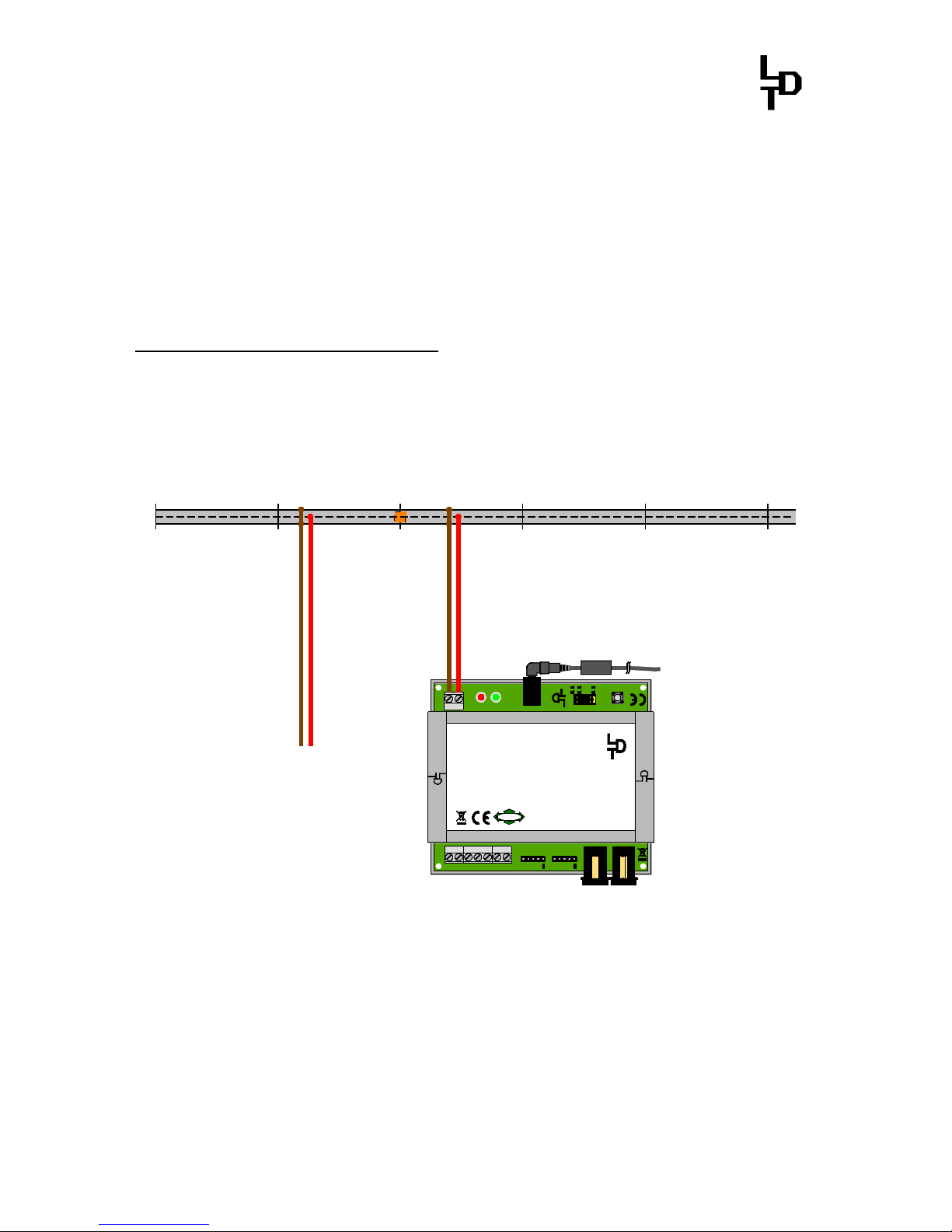
4.1. 3-Conductor Track System:
If the manufacturer of your digital command station permits a common layout ground
(“brown”) the center conductor of the 3-conductor track has to be isolated at the
cross over joints from one to the next booster electrical circuit. The isolated center
conductor gets the supply from the connection “red” of the clamp KL1 of the
DigitalBooster DB-4.
È
BU1
+
S1
DCCMM
JP1
JP2
JP3
JP4
OFFON
Auto Go
RailCom
ShortReport
red brown
LED1 LED2
GO STOP
+
Littfinski DatenTechnik (LDT)
KL1
K J
4,52,5
JP5
OUTIN
ST1 ST2
Rev. 1.4
DB-4
BU3
BU2
C D E
STOP/GO
KL2 KL4 KL3
Feedback
A
T
2,5 / 4,5 Ampere Booster für die Digitalformate MärklinMotorola, mfx®, M4 und DCC.
2,5 / 4,5 ampere booster for Märklin-Motorola, mfx®, M4
and DCC.
DB-4
DigitalBooster
Multi-Digital
L
ittfinski DatenTechnik (
LDT
)
D-25492 Heist
www.ldt-infocenter.com
Digital-Profi werden!
braun
brown
rot
red
Vom DB-4-Power-Supply
From DB-4-Power-Supply
rot
red
braun
brown
Von Digitalzentrale
oder Booster
From command station
or booster
J K J K
Booster separation by common layout ground with isolated center conductor
If the manufacturer of the digital command station does not permit a common layout
ground (“brown”) it is required additionally to isolate the rails at the cross over
joints.
If the manufacturer of the digital command station stipulates mandatory the
installation of a rocker switch at the cross sections of the center conductor this
switch has to be installed.
Page 11
DigitalBooster DB-4 – Manual
- 8 -
Alternative is it possible to use our Booster Keep Separate Module BTM-SG for the
cross over joints. This module separates electrically definite the booster sections
without rocker switch and provides the possibility to drive at slow speed at the cross
over sections.
BU1
+
S1
DCCMM
JP1
JP2
JP3
JP4
OFFON
Auto Go
RailCom
ShortReport
red brown
LED1 LED2
GO STOP
+
Littfinski DatenTechnik (LDT)
KL1
K J
4,52,5
JP5
OUTIN
ST1 ST2
Rev. 1.4
DB-4
BU3
BU2
C D E
STOP/GO
KL2
KL4 KL3
Feedback
A
T
2,5 / 4,5 Ampere Booster für die Digitalformate MärklinMotorola, mfx®, M4 und DCC.
2,5 / 4,5 ampere booster for Märklin-Motorola, mfx®, M4
and DCC.
DB-4
DigitalBooster
Multi-Digital
L
ittfinski DatenTechnik (
LDT
)
D-25492 Heist
www.ldt-infocenter.com
Digital-Profi werden!
braun
brown
rot
red
braun
brown
gelb
yellow
Vom Modellbahntrafo
From transformer
KL1KL2KL3KL4
BTM-SG
16...18V
Rev. 1.1
Littfinski DatenTechnik (LDT)
Booster Trennstellen Modul
Booster Keep Separate Module
~ ~
KL6
Sensor2
rot br. rot br.
Track
rot br.
Booster1
rot br.
Booster2
KL5
Sensor1
rot br.
Multi-Digital
Trennstellenisolierung mit automatischer Boosterumschaltung über Sensorgleise.
Booster Keep Separate Module.
Digital-Profi werden!
L
ittfinski DatenTechnik (
LDT
)
D-25492 Heist
www.ldt-infocenter.com
Booster Trennstellen Modul
BTM-SG
braun
brown
rot
red
braun
brown
rot
red
braun
brown
rot
red
Booster 2Sensor 2Sensor 1Booster 1
Von Digitalzentrale
oder Booster 1
From command station
or booster 1
Track
Umschaltgleis
Vom DB-4-Power-Supply
From DB-4-Power-Supply
J K
rot
red
braun
brown
Definite electrical separation of booster sections by implementing the Booster Keep Separate
Module BTM-SG.
Page 12

DigitalBooster DB-4 – Manual
- 9 -
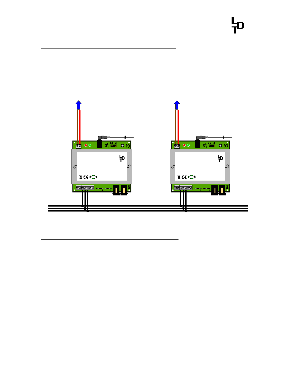
4.2. 2-Conductor Track System:
If the manufacturer of your digital command station permits a common layout ground
(“brown” or “J”) one rail of the 2-conductor track has to be isolated at the cross
over joints from one to the next booster electrical circuit.
If the manufacturer of your digital command station does not permit a common
layout ground („brown“) both rails have to be isolated at the cross over joints.
Ç
Ç
BU1
+
S1
DCC
MM
JP1
JP2
JP3
JP4
OFFON
Auto Go
RailCom
ShortReport
red brown
LED1 LED2
GO STOP
+
Littfinski DatenTechnik (LDT)
KL1
K J
4,52,5
JP5
OUTIN
ST1 ST2
Rev. 1.4
DB-4
BU3
BU2
C D E
STOP/GO
KL2 KL4 KL3
Feedback
A
T
2,5 / 4,5 Ampere Booster für die Digitalformate MärklinMotorola, mfx®, M4 und DCC.
2,5 / 4,5 ampere booster for Märklin-Motorola, mfx®, M4
and DCC.
DB-4
DigitalBooster
Multi-Digital
L
ittfinski DatenTechnik (
LDT
)
D-25492 Heist
www.ldt-infocenter.com
Digital-Profi werden!
Vom DB-4-Power-Supply
From DB-4-Power-Supply
Von Digitalzentrale
oder Booster
From command station
or booster
J K J K
rot
red
braun
brown
rot
red
braun
brown
Booster separation without common layout ground (both rails isolated)
Alternative is it possible to use our Booster Keep Separate Module BTM-SG for the
cross over joints. This module separates electrically definite the booster sections.
braun
brown
rot
red
J K
Vom DB-4-Power-Supply
From DB-4-Power-Supply
BU1
+
S1
DCCMM
JP1
JP2
JP3
JP4
OFFON
Auto Go
RailCom
ShortReport
red brown
LED1 LED2
GO STOP
+
Littfinski DatenTechnik (LDT)
KL1
K J
4,52,5
JP5
OUTIN
ST1 ST2
Rev. 1.4
DB-4
BU3
BU2
C D E
STOP/GO
KL2
KL4 KL3
Feedback
A
T
2,5 / 4,5 Ampere Booster für die Digitalformate MärklinMotorola, mfx®, M4 und DCC.
2,5 / 4,5 ampere booster for Märklin-Motorola, mfx®, M4
and DCC.
DB-4
DigitalBooster
Multi-Digital
L
ittfinski DatenTechnik (
LDT
)
D-25492 Heist
www.ldt-infocenter.com
Digital-Profi werden!
braun
brown
rot
red
braun
brown
gelb
yellow
Vom Modellbahntrafo
From transformer
KL1KL2KL3KL4
BTM-SG
16...18V
Rev. 1.1
Littfinski DatenTechnik (LDT)
Booster Trennstellen Modul
Booster Keep Separate Module
~ ~
KL6
Sensor2
rot br. rot br.
Track
rot br.
Booster1
rot br.
Booster2
KL5
Sensor1
rot br.
Multi-Digital
Trennstellenisolierung mit automatischer Boosterumschaltung über Sensorgleise.
Booster Keep Separate Module.
Digital-Profi werden!
L
ittfinski DatenTechnik (
LDT
)
D-25492 Heist
www.ldt-infocenter.com
Booster Trennstellen Modul
BTM-SG
braun
brown
rot
red
braun
brown
rot
red
braun
brown
rot
red
Von Digitalzentrale
oder Booster 1
From command station
or booster 1
Booster 2Sensor 2
Sensor 1
Booster 1
Track
Umschaltgleis
Definite electrical separation of booster sections by implementing the Booster Keep Separate
Module BTM-SG.
Page 13

DigitalBooster DB-4 – Manual
- 10 -
5. Booster in Operation:
All jumpers of the DB-4 are set ex-factory. The DigitalBooster DB-4 can be used
immediately at the supplied condition. The factory setting is recommended for the
first implementation of the unit.
For selecting different operation modes after the first implementation please attend
to the chapter “Adjusting Operation Modes with Jumpers”.
After switching-on the model railway layout at first the red LED of the DigitalBooster
DB-4 will glow. If the red and the green LED will alternate flash the supply voltage
has not been set correctly at the range of 15 to 24 Volt. Please check and correct
the voltage setting at the DB-4-PowerSupply.
If the red LED of the DigitalBooster DB-4 will glow constantly after switching-on
the layout the DB-4 is in operation mode and can be switched-on with the key “Go” of
the digital command station. After switching-on the green LED of the DB-4 will
glow and the unit will supply digital current to the connected track section.
The DigitalBooster DB-4 will be automatically switched-off if a short circuit will
occur at the track. The green LED switches off and the red LED will glow constant.
The DB-4 will report the short circuit via the employed booster bus to the digital
command station. Those will switch to ”Stop”.
After removing the short circuit you can switch-on again the digital current to the
track with the key “Go”.
If the current exceeds 2,5 Ampere within the track section the DigitalBooster DB-4
will switch-off as well and is reporting this overload to the digital command station
which will switch to “Stop”.
6. Adjusting Operation Modes with Jumper:
The various operation modes and functions of the DigitalBooster DB-4 can be
adjusted with the jumpers J1 to J5.
6.1. Select the Maximum Digital Current to 2,5 or 4,5 Ampere:
The Jumper J5 has been set ex factory. The DigitalBooster DB-4 supplies with this
setting a maximum output current of 2,5 Ampere to the track.
This limitation is suitable for the gauge N to prevent the excessive overload to
tracks, vehicle wheels and current transmittal in case of a short circuit.
Page 14

DigitalBooster DB-4 – Manual
- 11 -
If you use a larger and therefore mechanically and electrically more rugged gauge
you can remove the jumper J5. The DigitalBooster DB-4 will now supply a
maximum digital current of 4,5 Ampere to the connected track.
6.2. Select the Data Format for WatchDog- and On-/Off switch function:
The jumper J4 has been set ex-factory.
With this setting can be the WatchDog- and On-/Off switch function controlled by
your model railway software respectively via your digital command station by using the
Märklin-Motorola-Data Format.
If you want to use the DCC-Data Format for the WatchDog- and the On-/Off switch
function please remove the jumper J4.
6.3. RailCom®*-cutout Creation or Suppression:
The RailCom®*-cutout will be created if the jumper J3 has been set. If the Jumper
J3 has been removed there will be no RailCom®*-cutout created.
The selection with jumper J3 if the DigitalBooster DB-4 shall create or
suppress a RailCom®*-cutout is only possible if the data format for the WatchDogand On-/Off switch function has been set to DCC (Jumper J4 removed).
6.4. Short Circuit Report to the Command Station (Short Report):
If the Jumper J1 "Short Report " has been set the DigitalBooster DB-4 will report a
short circuit within the connected track section via the used booster bus to the digital
command station. In this case the digital command station will switch-off all
boosters.
If your model railway software includes a so called Booster-Management this
gadget can prevent that the digital command station will switch-off the complete
layout if a short circuit occurs within a booster section.
The trains will therefore stop only inside the booster section where the short circuit has
been occurred. All other booster sections will remain in function.
To initiate that the DigitalBooster DB-4 shall not report a short circuit to the digital
command station please remove the jumper J1.
Page 15

DigitalBooster DB-4 – Manual
- 12 -
With the output “Feedback“ of the DigitalBoosters DB-4 is it possible to inform your
model railway software if the tracks receive presently digital current from the DB-4 or
if the tracks are switched voltage-free caused by a short-circuit.
6.5. Automatic Switch-On (Auto Go):
With the jumper J2 “Auto Go” is it possible to adjust the DigitalBooster DB-4 that the
unit perform a continuous check every 5 seconds if a short-circuit is still present .
The DigitalBooster DB-4 will supply current to the connected track section
automatically if the short-circuit has been eliminated. The jumper J2 has be set for
this function.
The automatic switch-on function is not activated if the jumper J2 has been
removed.
For activating the automatic switch-on function “Auto Go” has the jumper J1
“Short Report” to be removed and therefore is the DigitalBooster DB-4 not reporting
recognized short circuits to the digital command station.
7. Addresses for WatchDog- and On-/Off switch function:
The WatchDog- and the On-/Off switch function of the DigitalBooster DB-4 will be
controlled via accessory addresses (turnout addresses) which are used as well for
the switching of turnouts or signals.
Accessory addresses are combined at groups of four. The addresses 1 to 4 are
forming the first group the addresses 5 to 8 the second group etc. The highest
valid four-fold address group for the programming of the DigitalBooster DB-4 is for
Märklin-Motorola data format the group 313 to 316 and for the DCC-data format the
group 1021 to 1024.
From our Web-Site you can download at the section ”Downloads” the file “FourFold-Address Blocks” for listing all valid four-fold address groups.
The WatchDog- and the On-/Off switch-function can be assigned to an own or as
well to a common four-fold address group. Separated address sections for the
WatchDog- and for the On-/Off switch-function are recommended if you use several
DigitalBooster DB-4. Then is it possible to release the WatchDog-Function of all
boosters via one common address.
For the On-/Off switch function is it possible to assign for this case for each
DigitalBooster DB-4 an individual address over an own four-fold address group.
The address for the WatchDog-Function is always the first address (basic address)
of a four-fold group. The address for the On-/Off switch-function is always the third
address (basic address + 2) of the programmed four-fold group.
Page 16

DigitalBooster DB-4 – Manual
- 13 -
The following programming samples are indicating how to employ four-fold
address groups with 8 keys of a switch board.
The address has been indicated between the respective pair of keys.
The two keys red and green for each address are the two possible switch
directions of this address with reference to the turnout direction round and straight.
If you use a remote control LH100 of company Lenz Elektronik there will be red the
minus- and green the plus key.
round / red / - round / red / - round / red / - round / red / -
1 2 3 4
straight / green / + straight / green / + straight / green / + straight / green / +
7.1. Common Address Section:
If there will be a common four-fold address block programmed for the WatchDog-
and the On-/Off switch function the DigitalBooster DB-4 will occupy 4 accessory-
or turnout addresses.
WatchDog On-/Off sw. Funktion
inactivated not used Stop not used
round / red / - round / red / - round / red / - round / red / -
1 2 3 4
straight / green / + straight / green / + straight / green / + straight / green / +
activated not used Go not used
WatchDog On-/Off sw. Function
With the above table has been the DigitalBooster DB-4 programmed for the
WatchDog- and the On-/Off switch function for a common address section of 1 to
4.
With the basic address 1 of the four-fold address block will be the WatchDog-
Function controlled. With the basic address + 2 and the address 3 as per sample
will be the On-/Off switch function controlled.
The addresses 2 and 4 will not be used.
7.2. Own Address Sections:
If there will be own four-fold address groups programmed for the WatchDog- and
On-/Off switch function there will be 8 accessory- or turnout addresses assigned
by the DigitalBooster DB-4.
Page 17

DigitalBooster DB-4 – Manual
- 14 -
At the following sample the On-/Off switch function assign the four-fold address
block 1 to 4 and the WatchDog-Function the addresses 5 to 8.
The On-/Off switch function will be controlled by the address 3 and the WatchDogFunction with the address 5.
On-/Off sw. Function
not used not used Stop not used
round / red / - round / red / - round / red / - round / red / -
1 2 3 4
straight / green / + straight / green / + straight / green / + straight / green / +
not used not used Go not used
On-/ Off sw. Function
WatchDog
inactive not used not used not used
round / red / - round / red / - round / red / - round / red / -
5 6 7 8
straight / green / + straight / green / + straight / green / + straight / green / +
active not used not used not used
WatchDog
7.3. Address Section Programming:
1. Switch-on your digital layout incl. DigitalBooster DB-4 (the green LED of the
DB-4 will glow).
Depress 1x short the key S1 next to the jumpers of the DB-4. Now the green
LED flashes. This indicates that the DB-4 is in the programming mode for the
address-section of the On-/Off switch-function. During the programming
process is the track section which is connected to the DB-4 switched voltage
free.
2. Switch now one turnout from the group of four which has been selected for
the address section of the On-/Off switch function via the keyboard of the
digital command station or the remote control. For programming the
address section you can send as well a turnout signal via your model
railway software. The transmitted data format (DCC or Märklin-Motorola)
has to match the data format you have selected with the jumper J4.
Remarks: It does not matter which of the four addresses from a group you
will use for programming.
If the DigitalBooster DB-4 understands the address the DB-4 will confirm the
assignment by flashing the green LED a little faster. Following the green
LED will flash slower again.
Page 18

DigitalBooster DB-4 – Manual
- 15 -
The programming for the on-/off switch function is now completed but can
repeated at any time.
3. Depress now again the key S1 to come into the programming mode for the
address section of the WatchDog-Function. The red LED flashes.
4. Switch now one turnout from the group of four which has been selected for
the address section of the WatchDog-Function via the keyboard of the
digital command station or the remote control. For programming the
address section you can send as well a turnout signal via your model
railway software.
Remarks: It is possible to select for the WatchDog-Function the same
address section as you used already for programming the On-/Off switch
function. But you can select as well an own four-fold address block for the
WatchDog-Function.
If the DigitalBooster DB-4 understands the address the DB-4 will confirm the
assignment by flashing the red LED a little faster. Following the red LED will
flash slower again. The programming for the On-/Off switch function is now
completed but can be repeated at any time.
Leave now the programming mode of the DB-4 by depressing again the
programming key S1. The programmed addresses are now permanently stored
but can be changed at any time by repeating the programming process. Now the
green LED will glow and the track section which is connected to the DB-4 will get
supply of digital voltage.
8. WatchDog: Communication with the Model Railway Software:
If your model railway software supports the WatchDog-Function of the DB-4
respectively our WatchDog-Decoder WD-DEC please register in your model railway
software your selected address for the WatchDog-Function. It is always the first
address (basic address) of the selected group of four.
Function:
After switching-on the DigitalBooster DB-4 is the WatchDog-Function not
activated to enable the operation of the model railway layout eventually without
PC-control via the digital command station.
The model railway software can activate the WatchDog-Function with the
command basic address “straight” and has to confirm always within 5 seconds with
a new command basic address “straight”. If there is no confirmation within 5
seconds the model railway software has lost control over the model railway
layout. The Digital Booster DB-4 will switch the track voltage free and all trains will
stop immediately. The red LED of the DB-4 will flash and indicates therefore the
switch-off situation.
Page 19

DigitalBooster DB-4 – Manual
- 16 -
After a new start of the digital command station, PC and model railway software
the DigitalBooster DB-4 will react immediately to the received commands and will
supply again digital current to the tracks.
If the model railway software will be finalized the software will deactivate at first the
WatchDog-Function with the command basic address “round” and the layout can
now operate without PC via the digital command station.
9. DB-4 switching On and Off via Accessory Address:
The DigitalBooster DB-4 can be switched On and Off via an accessory address
(turnout command). Address programming explained in chapter 6.
The DigitalBooster DB-4 can be switched Off via the basic address + 2 “round” of
the address block programmed for the On/Off-switch function. The DigitalBooster
DB-4 can be switched On via the basic address + 2 “straight”.
WatchDog or On-/Off sw. Function
inactive not used Stop not used
round / red / - round / red / - round / red / - round / red / -
1 2 3 4
straight / green / + straight / green / + straight / green / + straight / green/ +
WatchDog or not used Go not used
inactive On-/ Off sw. Funktion
The On-/Off switch function via Accessory- or Turnout Address has no function if
the Jumper J1 “Short Report” has been set.
via command station via accessory address
Jumper J1 "Short Report"
Stop Go Stop Go
set X X - removed X X X X
“X” indicates switching possible
“-“ indicates switching not possible
10. DB-4 switching On and Off via external push button:
The DigitalBooster DB-4 can be switched on and off with the external Stop/Go
Keys. These keys can be installed at the layout rim and used as emergency switchoff keys.
Page 20

DigitalBooster DB-4 – Manual
- 17 -
The external Stop/Go keys are only emergency shut-down keys if the jumper J1
“Short Report” has been set. In this function can be all boosters (as well as
eventually integrated booster of the digital command station) all together switched-off.
The switching-on of all boosters can be done only with the Go-Key of the digital
command station.
If the jumper J1 “Short Report” has been removed is it possible to switch the
DigitalBooster DB-4 which is connected to the external Stop/Go keys individually
On and Off.
Stop/Go
BU1
+
S1
DCCMM
JP1
JP2
JP3
JP4
OFF
ON
Auto Go
RailCom
ShortReport
red brown
LED1 LED2
GO STOP
+
Littfinski DatenTechnik (LDT)
KL1
K J
4,52,5
JP5
OUTIN
ST1 ST2
Rev. 1.4
DB-4
BU3
BU2
C D E
STOP/GO
KL2
KL4 KL3
Feedback
A
T
2,5 / 4,5 Ampere Booster für die Digitalformate MärklinMotorola, mfx®, M4 und DCC.
2,5 / 4,5 ampere booster for Märklin-Motorola, mfx®, M4
and DCC.
DB-4
DigitalBooster
Multi-Digital
L
ittfinski DatenTechnik (
LDT
)
D-25492 Heist
www.ldt-infocenter.com
Digital-Profi werden!
braun
brown
J
rot
red
K
Vom Modellbahntrafo
From transformer
Vom DB-4-PowerSupply
From DB-4-PowerSupply
Stop/Go
Fahren und Schalten
driving and switching
External Stop/Go-Key connection
via command station via ext. Stop/Go-Key
Jumper J1 "Short Report"
Stop Go Stop Go
set X X X removed X X X X
“X” indicates switching possible
“-“ indicates switching not possible
Page 21

DigitalBooster DB-4 – Manual
- 18 -
11. Feedback Report for Booster-Management:
The DigitalBooster DB-4 contains a Feedback Output for the information to the
model railway software if the tracks receive digital current from the DB-4 or if this
has been temporarily interrupted caused e.g. by a short circuit or by an emergency
shutdown.
BU1
+
S1
DCCMM
JP1
JP2
JP3
JP4
OFFON
Auto Go
RailCom
ShortReport
red brown
LED1 LED2
GO STOP
+
Littfinski DatenTechnik (LDT)
KL1
K J
4,52,5
JP5
OUTIN
ST1 ST2
Rev. 1.4
DB-4
BU3
BU2
C D E
STOP/GO
KL2
KL4 KL3
Feedback
A
T
2,5 / 4,5 Ampere Booster für die Digitalformate MärklinMotorola, mfx®, M4 und DCC.
2,5 / 4,5 ampere booster for Märklin-Motorola, mfx®, M4
and DCC.
DB-4
DigitalBooster
Multi-Digital
L
ittfinski DatenTechnik (
LDT
)
D-25492 Heist
www.ldt-infocenter.com
Digital-Profi werden!
braun
brown
J
rot
red
K
Vom DB-4-PowerSupply
From DB-4-PowerSupply
Fahren und Schalten
driving and switching
IN
10911
8765432
1
1213141516
KL6KL5KL4KL3KL2KL1
Littfinski DatenTechnik (LDT)
ST2ST1
Rückmeldemodul RM-88-N
16 - channel feedback module
Rev. 1.0
BU1 BU2
s88-N
OUT
IN
s88-N
OUT
Digital-Profi werden!
16 Rückmeldeeingänge für den
s88-Rückmeldebus.
Rückmeldemodul
RM-88-N
L
ittfinski DatenTechnik (
LDT
)
D-25492 Heist
www.ldt-infocenter.com
s88-N
Feedback report for Booster-Management via RM-88-N (s88-feedback bus)
BU1
+
S1
DCCMM
JP1
JP2
JP3
JP4
OFFON
Auto Go
RailCom
ShortReport
red brown
LED1 LED2
GO STOP
+
Littfinski DatenTechnik (LDT)
KL1
K J
4,52,5
JP5
OUTIN
ST1 ST2
Rev. 1.4
DB-4
BU3
BU2
C D E
STOP/GO
KL2 KL4 KL3
Feedback
A
T
2,5 / 4,5 Ampere Booster für die Digitalformate MärklinMotorola, mfx®, M4 und DCC.
2,5 / 4,5 ampere booster for Märklin-Motorola, mfx®, M4
and DCC.
DB-4
DigitalBooster
Multi-Digital
L
ittfinski DatenTechnik (
LDT
)
D-25492 Heist
www.ldt-infocenter.com
Digital-Profi werden!
braun
brown
J
rot
red
K
Vom DB-4-PowerSupply
From DB-4-PowerSupply
Fahren und Schalten
driving and switching
10911
8765432
1
1213141516
Littfinski DatenTechnik (LDT)
RS-16-O
Rev. 2.0
LED1
S1
Ref
K RJ S
14 .. 18V~
L
ittfinski DatenTechnik (
LDT
)
D-25492 Heist
www.ldt-infocenter.com
Digital-Profi werden!
16 galvanisch getrennte Rückmeldeeingänge
für den RS-Rückmeldebus.
Rückmeldemodul
RS-16 Opto
+ -
12...24VDC
Feedback report for Booster-Management via RS-16-O (RS-feedback bus)
Page 22

DigitalBooster DB-4 – Manual
- 19 -
12. Assembly Plan of the Basic PC-board:
Made in Europe by
Littfinski DatenTechnik (LDT)
Kleiner Ring 9
D-25492 Heist/Germany
Phone: 0049 4122 / 977 381
Fax: 0049 4122 / 977 382
Internet: http://www.ldt-infocenter.com
Subject to technical changes and errors. 07/2015 by LDT
Märklin and Motorola are registered trademarks.
*RailCom® is a registered trademark from the company Lenz Elektronik, Giessen, Germany.
 Loading...