

Page 1
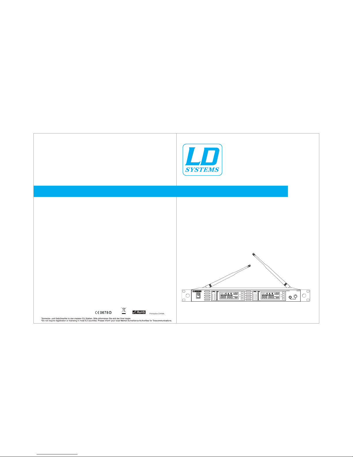
160 CHN UHF PLL True Diversity Wireless System
790,850 - 813,800 MHz* (838,850 - 861,800 MHz* X-Version)
Teleko mmuni katio nsbeh örde.
n
WS1000 - 2 (X) User Manualwww.ld-systems.com
A A
B B
6
5
4
3
2
1
6
5
4
3
2
1
-5 -5
-3 -3
0 0
+3 +3
+6 +6
AF AFRF RF
V V
SET
IR
GROUP CHANNEL
SCAN
FREQ
GROUP CHANNEL
SCAN
FREQ
POWER
-20 -20
-10 -10
ASC ASC
SET
WS 1000 R2
PHONESPHONES
UHF PLL Diversi ty
Dual Channel Wirel ess Receiver
Page 2

WS- 1000 Sy stem
Fre quenc y Band Se lecti on
Congra tulations! We lcome to the WS- 1000-2 wirel ess system. To users w ho need to build a n advanced
UHF radi o system, WS-1 000-2 provid es an excellen t solution. Wi th 160 frequen cy bands, WS-1 000 is
applic able for vario us occasions o f radio-cast s uch as live show s, broadcast , meetings, in strument
pickup s etc. Touch buttons an d liquid cryst al displays ar e equipped wit hin all the comp onents for fas t and
simple s ystem setup.
The “User Gu ide” and “ Quick Se tting Guide i ncluding in yo ur system will t ell you all the de tails
you need t o operate the sy stem efficien tly.
”
Most cou ntries close ly regulate th e radio freque ncies used in th e transmissi on of wireless i nformation .
These re gulations st ate which devi ses can use whic h frequencie s, and help to lim it the amount of R F
(radio f requency) in terference i n all wireless c ommunicati ons.
To be flexible en ough to operat e worldwide, W -1000 system o ffers a number of f requency ran ges. You
can choo se an apprecia te one accordi ng to the wirele ss regulatio n in your area.Av ailable band s are:
S -2
To facilitate s ystem setup an d protect agai nst RF interfe rence, each sy stem comes wit h multiple
predef ined frequen cy groups and ch annels.
When usi ng a double WS-1 000 system, th e operating fr equency will g enerally not h ave to be change d.
In an inst allation wit h multiple rec eiver/tran smitter syst ems, each syst em must operat e on a separate
channe l. The group and ch annel system p rovides an opt imum frequen cy spread when u sing multipl e
receiv er/transmi tter systems .
Within a s ingle freque ncy band, up to 8 in dividual rec eiver/tran smitter syst ems may be used in
a single i nstallatio n.
The Table of the Co ntent s
System Components
WS-1000-R2 Receiv er Features
WS-1000MD(C) Hand held Transmitter
WS-1000BP Body Pack Transmitter
System Setup
Rack-Mounting the R eceivers
Tips for Im proving System Performance
Troubleshooting
Specifications
CATALOGUE
1 2
3
4
5
6
7
8
9
9
10
790,850 - 813,800 MHz
838,850 - 861,800 MHz (X-Version)
Page 3

-
+
-
+
WS1 00ML
WS1 00MH
UHF PLL BodyPack Transmitter
UHF PLL BodyPack Transmitter
WS- 1000 R2 r eceiv er
2 “AA” ba tteri es
A 1/4” RF c onnec tor
Pow er supp ly
19” r ack ear s
Two an tenna s
Use r guide
WS1 000MD h andhe ld tran smitt er or WS 10 00MC (C onden ser)
WS- 1000B P bodyp ack tra nsmit ter
Mic ropho ne (cho ice of Ws 100ML La valie r
or WS 100MH H eadse t)
WS- 1000B P bodypa ck tra nsmit ter
1/4” t o mini 3- pin gui tar cab le
System Components
All s ystem s inclu de:
Voca list sy stem in clude s:
Lav alier / Heads et syst em incl udes:
Gui tar sys tem inc ludes
3 4
OFF
ON
GROUP CHANNEL
INFRARED
BATT
160 CHN UHF PLL True Diversity Wireless System
790,850 - 813,800 MHz* (838,850 - 861,800 MHz* X-Version)
WS1000-2 (X)
1/4 inch mi x outpu t jack
XLR m ix outp ut jack
Cha nnel 2 XL R outpu t jack
Cha nnel 1 XL R outpu t jack
Cha nnel 1 Fi ne adju stmen t
of mu te thre shold l evel
AC ad apter j ack
Ant enna ja ck A
WS 1000R2 Receiver Features
Fro nt Pane l
Rea r Panel
1
2
3
4
5
6
5
Sys tem men u upwar d butto n
Ple ase see “S ystem S etup” on P age 8
Sys tem set up butt on
Ple ase see “S ystem S etup” on P age 8
Sys tem men u downw ard but ton
Ple ase see “ S ystem S etup” on P age 8
Syn c Butto n
Pre ss to ini tiate I R conne ction b etwee n
rec eiver a nd tran smitt er.
Inf rared ( IR)
Mon itor ea rphon e jack
Mon itor vo lume
win dow
On/ Off swit ch
Ant enna A rece iver in dicat or ligh t
Lig ht glow s when Ant enna A is on .
Ant enna A RF ind icato r light
Ant enna B RF i ndica tor lig ht
Ant enna B re ceive r indic ator li ght
Lig ht glow s when Ant enna B is o n .
Cha nnel 1 au dio ind icato r light
Cha nnel 1 LC D panel
Ple ase see “S ystem S etup” on P age 8
Ant enna ja ck B
Dat a input j ack
Con nect to c omput er cont rol
Dat a outpu t jack
Con nect to c omput er cont rol
Cha nnel 2 Fi ne adju stmen t of mute t hresh old lev el
It is t he mute e nabli ng thre shold v alue, w hich is f actor y
def ault an d usual ly no nee d to adju st, if th ere are a ny
int erfer ence si gnals , this th resho ld valu e can be in creas ed
by tu rning t he knob c lockw ise unt il RF sig nal lam p goes ou t.
11
10
7
8
9
12
13
14
6
7
9
8
POWER
A A
B B
6
5
4
3
2
1
6
5
4
3
2
1
-20
-10
-5
-3
0
+3
+6
AF
RF RF
V
ASC
SET
IR
GROUP CHANNEL
SCAN
FREQ
-20
-10
-5
-3
0
+3
+6
AF
V
ASC
SET
WS 1000 R2
PHONESPHONES
UHF PLL Diversi ty
Dual Channel W irele ss Rece iver
GROUP CHANNEL
SCAN
FREQ
1
2
3
1110
4
5
6
7
8 9
12 13 14
ANTENNA-AANTENNA-B
2 IN 1 MIX
UNBAL OUTPUT
CHANNEL1
XLR BALANCED -1 2dBV
CHANNEL2
XLR BALANCED -1 2dBV
2 IN 1 MIX
XLR BALANCED -1 2dBV
AF OUTPUT
MADE IN CHINA
Data Input
Data Output
CHANNEL 2
MUTE LEVEL
CHANNEL 1
MUTE LEVEL
D.C.12-18V I N
500mA
+ +
--
11101
2
3 4 5 6 7 8 9
2
3
4
1
11
10
A A
B B
6
5
4
3
2
1
6
5
4
3
2
1
-5 -5
-3 -3
0 0
+3 +3
+6 +6
AF AFRF RF
V V
SET
IR
GROUPCHANNEL
SCAN
FREQ
GROUPCHANNEL
SCAN
FREQ
POWER
-20 -20
-10 -10
ASC ASC
SET
WS 1000 R2
PHONESPHONES
UHF PLL Diversity
Dual Channel Wireless Receiver
A A
B B
6
5
4
3
2
1
6
5
4
3
2
1
-5 -5
-3 -3
0 0
+3 +3
+6 +6
AF AFRF RF
V V
SET
IR
GROUPCHANNEL
SCAN
FREQ
GROUPCHANNEL
SCAN
FREQ
POWER
-20 -20
-10 -10
ASC ASC
SET
WS 1000 R2
PHONESPHONES
UHF PLL Diversity
Dual Channel Wireless Receiver
Page 4
6
7
1
2
3
4
5
1
2
3
4
5
6 7
8
8
Ope n
Clo se
2
1
select
9
9
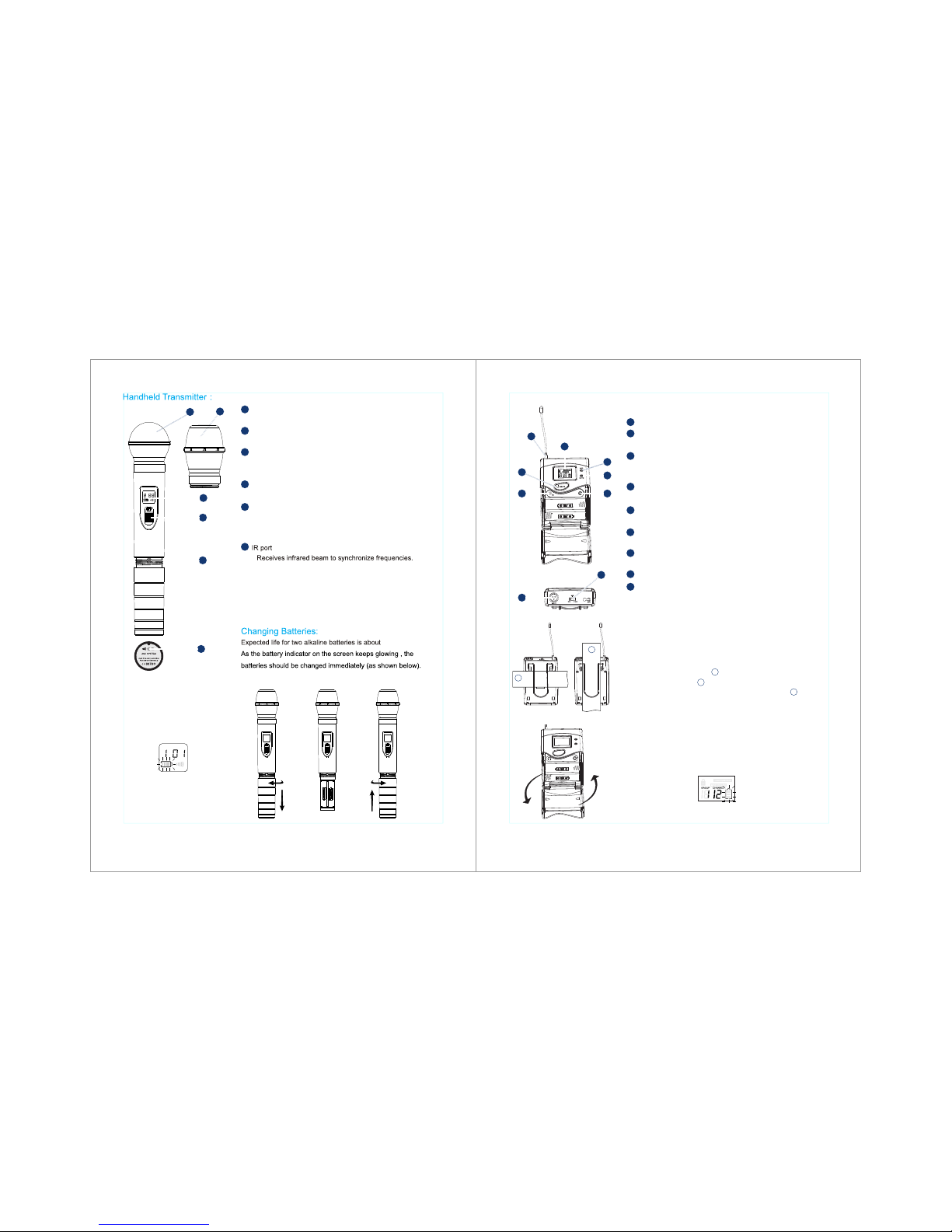
Wearing the Back pack Tra nsmit ter:
Cha nging b atter ies:
Expected life for Two Alkaline batteries is approximately 13 hours.
When the transmitter light glows red, the batteries should be
changed immediately, as shown on the left.
Cli p the tra nsmit ter to be lt , or sli de a guit ar stra p throu gh
the t ransm itter c lip ,as s hown
For b est res ults, s lide th e trans mitte r until t he belt i s
pre ssed ag ainst t he base f or the cl ip.
1
1
2
WS- 1000B P Bodyp ack Tran smitt er
Antenn a
LCD pane l
Please s ee “System Setu p” on Page 7.
IR
Receiv e IR signals to sy nchronize fr equencies.
window
Select b utton
Please s ee “System Setu p” on Page 7
3-pin Mi crophone Inp ut Jack
Gain adj ustment swit ch and mute indi cator
Two gain set tings are avai lable on WS-10 00BP,
choose t he appropria te setting for y our instrume nt
Mic: mic rophone
0: Guita r with passive p ickups
-10dB: G uitar with act ive pickups
Power/ ASC indicato r
Glowin g green: batte ry power low
Flash gr een: IR transm ission in proc ess
Features:
Mute Ind icator
Red ligh t on indicate Mu te mode
Power/ Mute switch
Push for 3 s econd to turn on /off
5 6
BATT
1
2
3
4
1
2
3
4
GROUP CHANNEL
INFRARED
GROUP CHANNEL
INFRARED
BATT
5
5
6
6
Con denso r mic (WS -1000 MC)
Dyn amic mi c (WS-1 000MD )
LCD s creen
Pow er sour ce cont rolli ng swit ch
Mic ropho ne inpu t sensi tivit y adjus tment .
Lef t turn fo r outpu t level d ecrea se, rig ht
tur n for out put lev el incr ease.
Ple ase Se e “sy stem s etup ” on page 7 .
Functions:
14
hours
Page 5
1
2
3
Sys tem Set up
GROUP
GROUP
GROUP
GROUP
CHANNE L
CHANNE L
CHANNE L
CHANNE L
SCAN
SCAN
SCAN
SCAN
FREQ
FREQ
FREQ
FREQ
1
2
3
4
GROUP CHANNE L
SCAN
FREQ
6
GROUP CHANNE L
SCAN
FREQ
5
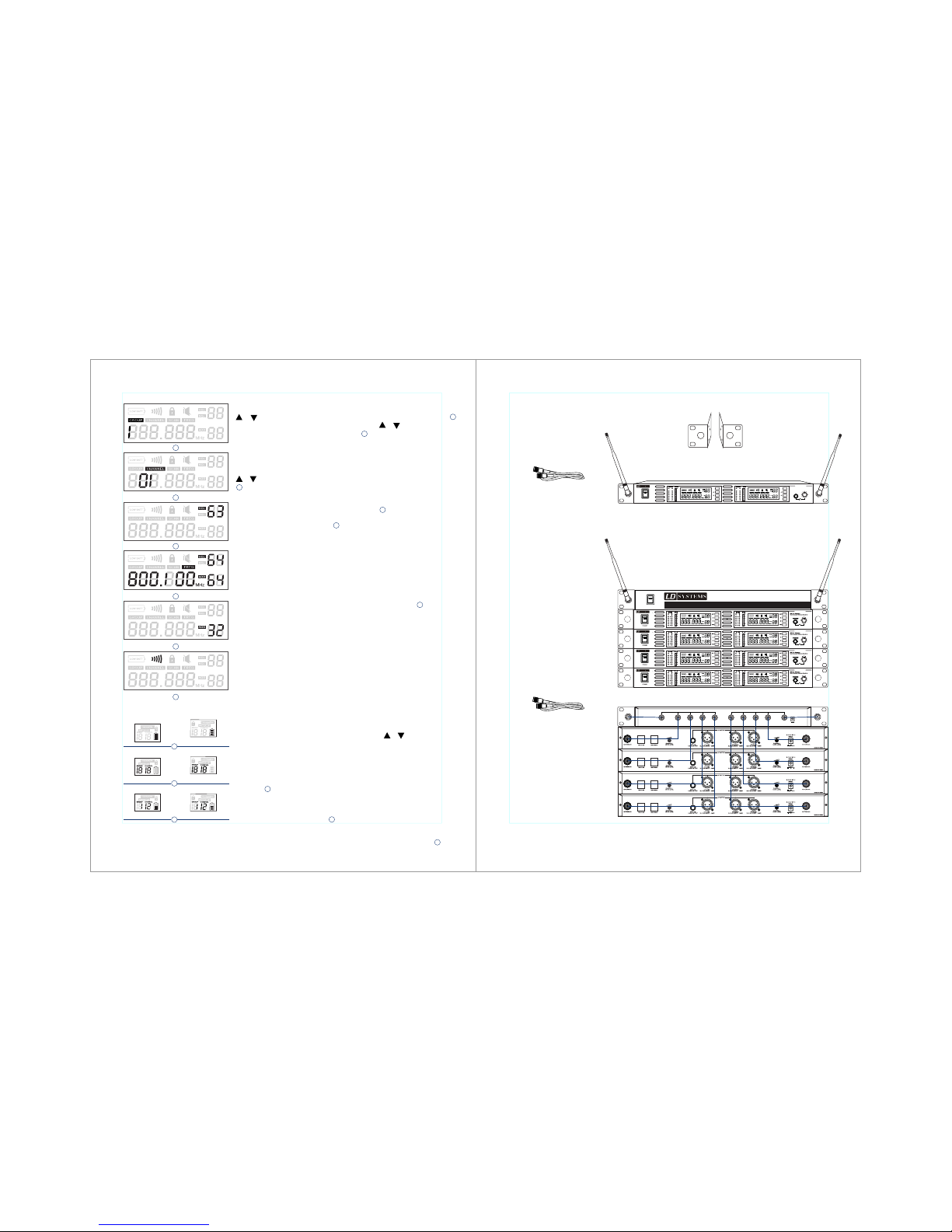
Group and Channel Selection:Press “set” button, “Group” flash, press
or to choose the appreciate frequency group, as shown on the left ;
press “ SET” again , “CHANNEL” flashes,press or to choose the
appreciate channel, as shown on the left shown.
For best results when operating multiple systems, set all systems to a
single group: then set each system to a unique channel within that group.
Receiver Volume Setting:
The receiver has electric volume control, as on the normal display, press
or directly to control the output volume (altogether 64 steps) as
shown on the left. We recommend a Set-Up between level 42 to 45.
Normal Display:
RF level,group no,channel no,frequenay as left .
Infrared Frequency Scanning :
Note:In multiple receivers system, every receiver's address must be
different!
Turn off the transmitter and open the battery canister (only at bodypack handheld has the IR receiver at the bottom of the mic see page 5 point 6)
turn the IR window on the receiver IR window, press “ASC” button,
and turn on the transmitter again.
Turn the Bodypack receiver IR port on the receiver IP window,then press
“ASC” button, and then press the “ASC” button on the bodypack transmitter.
The receiver keeps transmitting sync frequencies each time you press
the “ASC”button, and the sign “INFRARED” flash as shown on the left.
Each time turn on the transmitter and press the “ASC” button at the
receiver, the reiceiver will start the IR receiving system for 25 seconds.
The handheld transmitter lights up when the IR receiver system starts,
the whole display within the backpack transmitter flashes
(the IR indicator light also flashes at the same time)
Attention: The distance of the receiver and the transmitter should be
less than 0.5m as the IR connection is setting; only can turn one
transmitter IR window on the receiver at each IR connection when
multi-system is using.
Auto-Scan Function:
The WS1000 Series has a frequency Auto-Scan Function which makes
it easier to find the next interference free Channel within 1 group.
It may can happen that you still have to find the next interference free
channel manual.
Press “SET” Button 3x until “SCAN” flash. Press or to start the Auto
Scan Run, which may will find the next next interference free Channel
within the selected group.
Battery Status:
The handheld transmitter and the bodypack transmitter had six
levels,as shown on the left.
Group and Channel Display:
After the finishing the connection of the receiver and the transmitter,
the transmitters receiver keeps displaying the numbers of the group
and channel for 5 seconds, as shown on the left, then back to the
normal status display.
Normal Display:
The transmitters shows battery power and working frequency, as
shown on the left.
Rec eiver P rogra mming
1
1
2
2
3
4
3
6
Transmitter Status Display
5
Handheld
Transmitter
Bodypack
Transmitter
Rac k-Mou nting t he Rece iver
7 8
Two TNC connecting cable (included)
Two TNC connector (inlcuded)
One R eceiv er
(wi th 19” Ra ck Ears )
Ten TNC connecting cable (included)
Two TNC connector (included)
Four receivers
WS100DA Antenna Distributor
(optional)
(19 ” Rack Ea rs Incl uded)
A A
B B
6
5
4
3
2
1
6
5
4
3
2
1
-5 -5
-3 -3
0 0
+3 +3
+6 +6
AF AF
RF RF
V V
SET
IR
GROUP CHANNEL
SCAN
FREQ
GROUP CHANNEL
SCAN
FREQ
POWER
-20 -20
-10 -10
ASC ASC
SET
WS 1000 R2
PHONESPHONES
UHF PLL Diversity
Dual Channel Wireless Re ceive r
POWER
UHF ANTENNA DISTRIBUTE IMPLEMENT
WS100ADWS100AD
ANTENNA-B
ANT-1 ANT-1 ANT-2 ANT-2 ANT-3 ANT-3 ANT-4 ANT-4 ANTENNA-A
D.C.12-18V IN
200mA
+
-
Mai ntain a l ine of si ght bet ween
tra nsmit ter and a ntenn a.
WS 1000 R2
WS 1000 R2
WS 1000 R2
WS 1000 R2
Page 6
Mainta in a line of sight b etween trans mitter and ant enna.
Avoid pla cing the recei ver near meta l surfaces or an y digital equi pment (CD play ers, compute s, etc)
Keep the r eceiver away f rom the wall and o ver 1m to the grou nd
Cellul ar telephone s and two-way ra dio and so on can in terfering th e transmitti ng frequenci es,
mainta in a distance fr om the interfe ring equipme nts or any cause i nterfering .
Iss ue Indi cator S tatus So lutio n
Trip s for imp rovin g Syste m Perfo rmanc e
Trou bles Sh ootin g
Tran smitt er LCD of f
Turn o n trans mitte r
Mak e sure th e +/- ind icato r on batt ery
mat ch the tr ansmi tter te rmina ls
No so und or fa int
sou nd
Rec eiver L CD off Mak e sure AC ad apter i s secur ely
plu gged in to elec trica l outle t and int o
DC in put con necto r on rear p anel of
rec eiver.
Rec eiver R F indic ator gl ows Tu rn the re ceive r up
Turn u p the Gai n adjus tment s witch i n
the t ransm itter
Che ck the po wer con necti on of the
rec eiver a nd ampl ifier o r mixer
Rec eiver R F indic ator off ,
tra nsmit ter LCD o n
Take the r eceiv er awa y from th e metal
obj ects
Che ck whet her the re is ham per bet ween
rec eiver a nd tran smitt er
Mov e the tra nsmit ter nea r the rec eiver
Che ck the re ceive r and tra nsmit ter
whe ther us e the sam e frequ ency
The ba ttery p ower in dicat or
lig ht on LCD f lashe s
Cha nge the b atter ies in tr ansmi tter
Dis torti on or
unw anted n oise bu rsts
Rec eiver d ispla y indic ators
ant enna ac tivit y
Rem ove nea rby sou rces of R F inte
rfe rence (CD pla yers, c omput ers , dig ital
effe cts ,in -ear mo nitor s ystem s, etc. )
Dis torti on leve l
inc rease s gradu ally
Sou nd leve l differ ent
fro m cable d guita r or
mic ropho ne, or wh en
usi ng diffe rent gu itars
Adju st tran smitt er agai n and rec eiver
vol ume as ne cessa ry
Tran smitt er powe r indic ator
lig ht flas hing on t he LCD
Rep lace tr ansmi tter ba tteri es
Spe cific ation s
Frequency Range and Transmitter Output level
Operating Range under Typical Condition:
80m (240 ft.)
Note: actual range depends on RF signals
absorption,reflection, and interference.
Audio Frequency Response (+/-3 dB):
60Hz~16KHz
Total Harmonic Distortion
( +/- 30 KHz deviation,1 KHz tone):
<1%
Dynamic Range:
>90 dB (A –weighted)
Operating Temperature Range:
-10 C to +50 C
Note: battery characteristics may limit
the range
Audio Input Level Maximum:
0 dBV maximum at mic again position
+10 dBV maximum at 0 dB gain position
+20 dBV maximum at –10 dB gain position
Gain adjustment Range:
30 dB
Input Impedance:
470 kohm
Dimensions:
89mm H × 65mm W × 24mm D
Weight:
85 g without batteries
Power Requirement:
Two “AA” size alkaline or rechargeable batteries
Battery life:
Up to 13 hours (Alkaline)
Band Range Transmitter RF level
UA 518-548 MHz 13dBm
UB 630-660 MHz 13dBm
UC 740-770 MHz 10dBm
UD 800-822 MHz 10dBm
UE 838-865 MHz 10dBm
Sys tem
Bod y pack Tra nsmit ter
Dimens ions (includ ing the microp hone):
243mm × 50 mm Diameter
Weight:
300 g
Batter y Requiremen ts:
2 “AA” alkal ine batterie s or rechargea ble batterie s
Batter y Life:
Up to 14 hou rs (Alkaline )
Audio Ou tput Level Max imum (ref. +/- 30 KHz, 1 KHz):
XLR conn ector (into 60 0 load): - 12 dBV
1/4inc h connector (i nto 3000 l oad): -18 dBV
Output I mpedance:
XLRcon nector 200oh ms
1/4inc h connector 1k ohm
XLR Outp ut:
Impeda nce balanced
Pin 1: Gro und
Pin 2: (+)
Pin 3: (-)
:
:
5 410 8
:
25
Power Re quirements
12-18 Vd c at 1000mA, sup plied by exter nal power supp ly
Ω
Ω
Sensit ivity (inter mediate freq uency adjust ment
audio no ise output <-9 3 dBm)
Image Re jection
> 90 dB
Dimens ions
4 mm H × mm W × 1 0mm D
Weight
00 g
Rec eiver
Han dheld Tr ansmi tter
9 10
Page 7
(Applicable in the European Union and other European countries with separate
collection systems)
This marking shown on the product or its literature, indicates that it should not be
Disposed with other household wastes at the end of its working life. To prevent possible
harm to the environment or human health from uncontrolled waste disposal, please
Seperate this from other types of wastes and recycle it responsibly to promote the
sustainable reuse of material resources.
Household users should contact either the retailer where they purchased this product, or
their local government office, for details of where and how they can take this item for
environmentally safe recycling.
Business users should contact their supplier and check the terms and conditions of the
purchase contract. This product should not be mixed with other commercial wastes for
disposal.
(Waste Electrical & Electronic Equipment)
Correct Disposal of This Product
Recycling
(Batteries or rechargeable batteries)
The supplied batteries or rechargeable batteries can be recycled. Please dispose of them as special
waste or return them to your specialist dealer. In order to protect the environment, only dispose
exhausted batteries. Together for a good nature.
EG-Konformitätserklärung
Diese Geräte entsprechen den grundlegenden Anforderungen und den weiteren Vorgaben der Richtlinien 1999/5/EU, 89/336/EU und
73/23/EU. Die Erklärung steht im Internet unter zum Download zur Verfügung.
CE Declaration of Conformity
This equipment is in compliance with the essential requirement and other relevant provisions of Directives 1999/5/EC, 89/336/ES or
73/23/EC. The declaration is available for donwload on the internet site at www.adamhall.com. Before Putting the device into
operation, please observe the respective country-specific regulations!
Déclaration de conformité pour la CEE
Ces appareils sont conformes aux exigencies essentielles et aux autres dispositions pertinentes de les Directives 1999/5/EC,
89/336/EC et 73/23/EC. Vous trouvez cette
declaration dans la internet sous www.adamhall.com. Avant d'utiliser l'appareil, veuillez observer les dispositions légales en vigueur
dans votre pays.
Dichiarazione di vonformità UE
I presenti apparecchi sono conformi ai requisiti fondamentali e alle ulteriori prescrizioni delle normative 1999/5/EU, 89/336/UE e
73/23/UE. Il dichiarazione disponibile sul sito Internet
. Prima della messa in funzione seguite le prescrizioni vigenti nel paese nel quale viene utilizzato!
Declaración de Conformidad
Este equipo cumple tanto los requisitos esenciales como otras disposiciones de las Directivas 1999/5/CE, 89/336/CE y 73/23/CE. Si
desea leer el declaración, visite la página www.adamhall.com. Anterior a la puesta en funcionamiento deberán observarse las
correspondientes ordenanzas nacionales!
EU-verklaring van overeenstemming
Deze apparaten voldoen aan de fundamentele eisen en overige voorschriften van de richtlijnen 1999/5/EU, 89/336/EU en 73/23/EU.
Het verklaring is op internet onder www.adamhall.com beschikbaar. Voor inbedrijfstelling dient u de afzonderlijke landspecifieke
voorschriften in acht te nemen!
www.adamhall.com
www.adamhall.com
Safety instructions
No user serviceable parts inside! Never open the transmitter, otherwise you can receive an
electric shock. If units are opened by customers in breach of this instruction, the warranty
Becomes null and void.
Use the transmitter in dry rooms only. Never expose it to water (eg: never place it in a
position where it could be subjected to water splashes). Do not place any objects containing
liquids on the top of the unit.
Keep the transmitter away from direct sunlight, central heating radiators, electric heaters and
similar sources of heat. Ensure sufficient ventilation, especially when it is mounted into a 19”
rack.
Use a damp cloth for cleaning the unit. Do not use any cleansing agents or solvents.
11 12
 Loading...