

Page 1
USER´S MANUAL
BEDIENUNGSANLEITUNG
MANUEL D`UTILISATION
MANUAL DE USUARIO
INSTRUKCJA OBSŁUGI
MANUALE D‘ USO
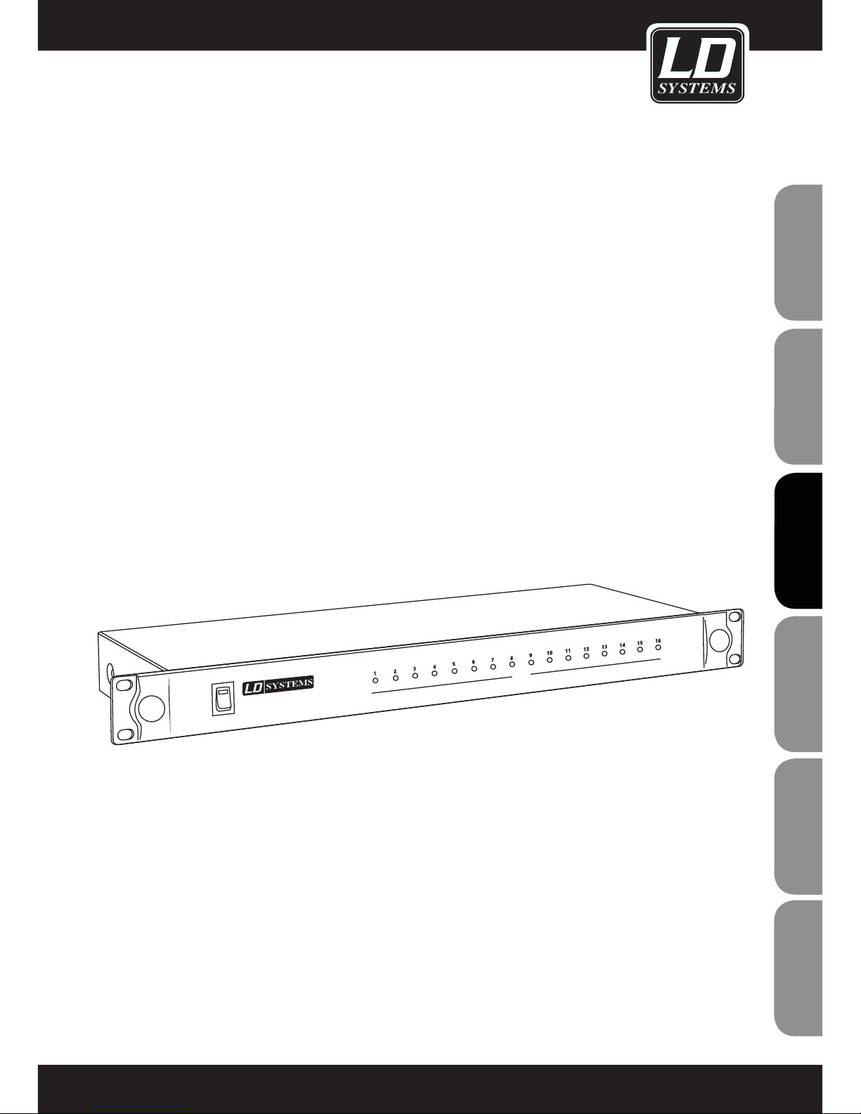
LD WIN42 CONTROLLER HUB
WIN42HUB
POWER
WIN42 CONTROLLER HUB
COM
Page 2

2
ENGLISHDEUTSCHFRANCAIS
FRANCAISFRANCAIS FRANCAISFRANCAIS
ESpAñoLpoLSKIITALIANo
Thank you for choosing LD-Systems!
We have designed this product to operate reliably over many years. Therefore LD-Systems guarantees for high
quality products with its name and many years of experience as a producer.
Please, take a few moments to read these instructions carefully, as we want you to enjoy your new LD-Systems
products quickly and to the fullest.
For information about LD-Systems check out our website WWW.LD-SYSTEMS.COM
Introduction
The LD Systems WIN42HUB and the associated WIN42 CONTROL CENTER software enable you to monitor and
control up to 16 WIN42 wireless systems. Clearly arranged graphics give you control over the radio frequency,
battery status, audio level, and much more for each individual WIN42 wireless systems connected. In addition,
the software has an "environment scan" feature with the help of which you can scan the respective location for
unused frequencies.
Page 3

3
ITALIANOPOLSKIESPAÑOL
FRANCAISFRANCAIS FRANCAISFRANCAIS
FRANCAISDEUTSCHENGLISH
POWER
WIN42 CONTROLLER HUB
COM
LD WIN42HUB
WIN42HUB
Page 4

4
ENGLISHDEUTSCHFRANCAIS
FRANCAISFRANCAIS FRANCAISFRANCAIS
ESpAñoLpoLSKIITALIANo
1. Please read this information carefully.
2. Keep all information and instructions in a safe place.
3. Please follow the instructions.
4. Please observe all warnings. Don‘t remove safety instructions or any other information located on the device.
5. Use the device only in the intended manner.
6. Use only stable and appropriate stands and/or mounts when the device is permanently installed. Make certain
that wall brackets are firmly secured. Make certain that the unit is installed securely and cannot fall down.
7. When installing please observe the corresponding safety standards for your country.
8. Do not install the device near radiators, heat accumulators, ovens or other sources of heat. Make certain that
the device is always installed so that is cooled sufficiently and cannot overheat.
9. Do not place open sources of ignition, e.g., burning candles, on the device.
10. Do not cover ventilation slots.
11. Do not operate the device in the immediate vicinity of water. Do not expose this equipment to combustible
materials, liquids or gases.
12. Please make certain that dripping or splashing water cannot get inside the device. Do not put objects filled
with fluids, such as vases or drinking vessels, on top of the device.
13. Make certain that objects cannot fall into the device.
14. Use the device only with accessories with which the manufacturer intends the device to be used.
15. CAUTION: If this device has a mains connector equipped with protective earth, it must be connected to a
mains socket with a protective ground connection. Never disable the function of the protective ground connection
of the included power cord.
16. Do not turn on the device immediately if it was exposed to strong temperature fluctuations (for example after
transportation). Moisture and condensation may damage the device. Leave the device switched off until it has
reached room temperature.
17. Do not open the device and do not make any changes to the device.
18. Before connecting to mains power, make certain that the mains voltage and the mains frequency are the
same as the operating values of the device (see type label). If the device is equipped with a supply voltage selector switch, make certain that the values of the device match the values of the mains power before connecting.
If the plug on the included cord does not fit your mains outlet, contact your electrician.
19. Make certain that the power cord is not stepped on. Protect the power cord against pinching, especially at
the device plug and the power plug.
20. In order to prevent damage or accidents, for example, due to tripping hazards, check all connections once
you have connected the device.
21. When connecting the device, make certain that the power plug remains readily accessible.
Always pull out the power plug when the device is not in use or when you clean the device. Disconnect the
power cord by pulling the plug not the cable. Never touch the power cable and power adapter with wet hands.
22. Avoid switching the device on and off at short intervals, because it may shorten the durability of the device.
23. IMPORTANT: Replace fuse only by fuse of same type and rating! If fuse blows repeatedly please contact
authorized service center!
24. In order to disconnect the device completely from the mains voltage, the power plug must be unplugged.
25. If your device is equipped with a Volex power connector, the matching Volex device plug must be unlocked
in order to disconnect it. This also means that a tug on the power cord can pull the device out of place, thus
causing personal injuries and/or property damage. Thus please make certain to route your cables carefully.
PREVENTIVE MEASURES:
Page 5

5
ITALIANOPOLSKIESPAÑOL
FRANCAISFRANCAIS FRANCAISFRANCAIS
FRANCAISDEUTSCHENGLISH
ENGLISH
ITALIANOPOLSKIESPAÑOL
FRANCAIS
5
26. If there is a risk of lightning strike or during extended periods of disuse, unplug the power plug.
27. During transport, make certain that the equipment being transported cannot fall down and possibly
cause personal injuries and/or property damage.
28. If your device no longer works properly, if it has been exposed to liquids or an object has fallen inside it or
if it has been damaged in some other manner, turn the device off immediately und unplug the power plug. This
device should be repaired only by authorized experts.
29. Use only a dry cloth to clean the device.
30. Comply with all of the disposal laws that are applicable in your country. During disposal, please separate
plastic and paper/cardboard.
31. Plastic bags must be kept out of the reach of children.
CAUTION
RISK OF ELECTRIC SHOCK
DO NOT OPEN
PREVENTIVE MEASURES:
CAUTION:
To reduce the risk of electric shock, do not remove cover (or back). No user serviceable parts inside. Refer
servicing to qualified personnel.
The lightning flash with arrowhead symbol within an equilateral triangle is intended to alert the
user to the presence of uninsulated “dangerous voltage” within the product´s enclosure that may be
of sufficient magnitude to constitute a risk to persons.
The exclamation mark within an equilateral triangle is intended to alert the user to the presence of
important operating and maintenance (servicing) instructions in the literature accompanying the
appliance.
CAUTION! HIGH VOLUME!
You will operate this transmission system for professional use. Therefore the commercial use of this equipment
is liable to the rules and regulations of the Accident Prevention & Insurance Association of your industry sector.
Adam Hall as a manufacturer is bound to inform you formally about the existence of eventual sanitary risks.
Risk of hearing damage due to prolonged exposure to excessive volumes: The loudspeaker is easily capable of
generating sound pressure levels (SPL) sufficient to cause permanent hearing damage to performers, production
crew and audience members. Caution should be taken to avoid prolonged exposure SPL in excess of 90 dB.
ENGLISH
Page 6

6
ENGLISHDEUTSCHFRANCAIS
FRANCAISFRANCAIS FRANCAISFRANCAIS
ESpAñoLpoLSKIITALIANo
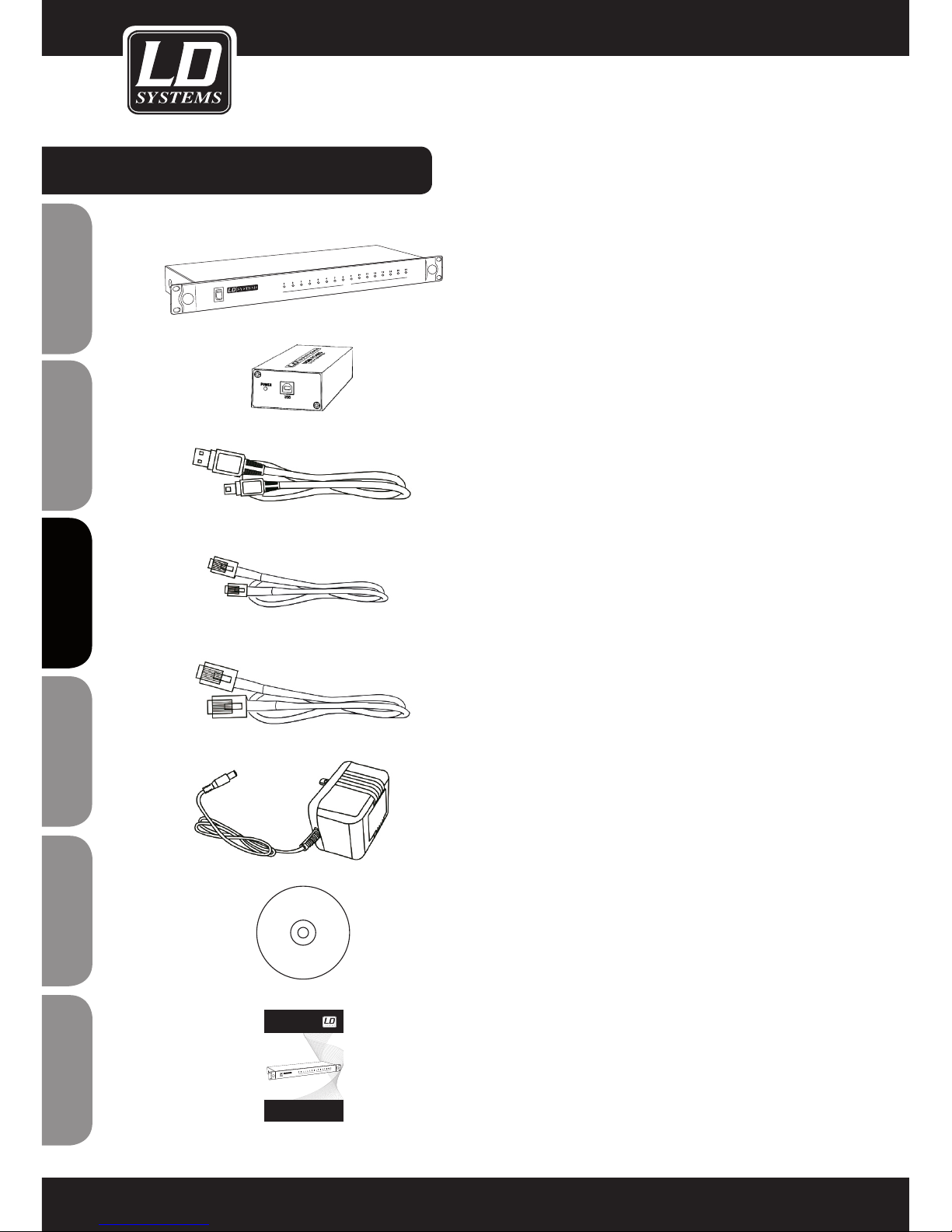
PACKAGE CONTENTS:
1 x WIN42 CONTROLLER HUB
1 x WIN42 USB to RS485 converter
1 x USB cable
16 x RJ11 cable
1 x RJ45 cable
1 x power adapter
1 x software CD
1 x User's Manual
POWER
WIN42 CONTROLLER HUB
COM
USER´S MANUAL
BEDIENUNGSANLEITUNG
MANUEL D`UTILISATION
MANUAL DE USUARIO
INSTRUKCJA OBSŁUGI
MANUALE D‘ USO
LD WIN42 CONTROLLER HUB
WIN42HUB
POWER
WIN42 CONTROLLER HUB
COM
Page 7

7
ITALIANOPOLSKIESPAÑOL
FRANCAISFRANCAIS FRANCAISFRANCAIS
FRANCAISDEUTSCHENGLISH
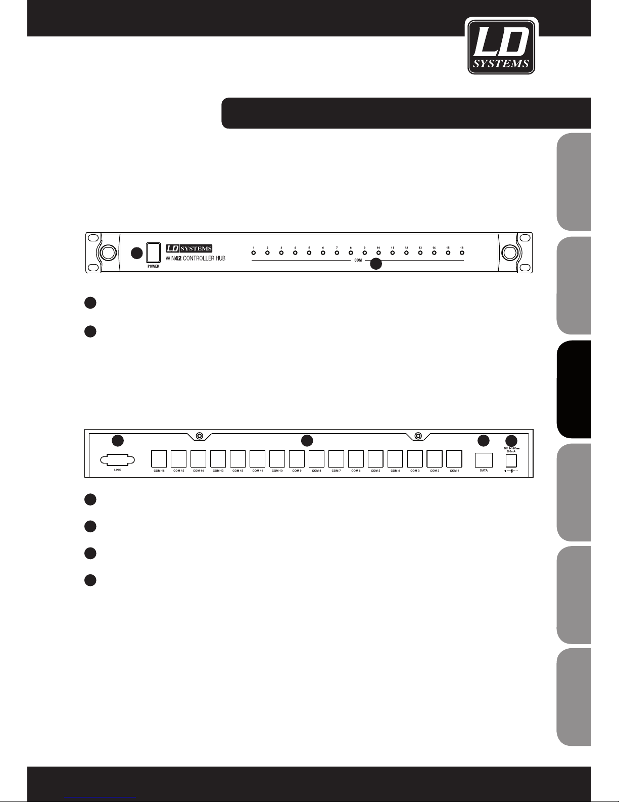
FRONT / REAR PANEL:
1
ON / OFF SWITCH
2
INDICATOR LEDS 1-16 FOR WIN42 RECEIVERS 1-16
1
AC ADAPTER CONNECTOR (9 - 18 V DC, 300 MA)
2
DATA PORT FOR USB TO RS485 CONVERTER
3
DATA CONNECTORS (COM 1 - 16) FOR WIN42 RECEIVERS
4
PROVISION FOR PORT EXPANSION (CURRENTLY UNAVAILABLE)
FRONT PANEL
REAR PANEL
1
1
2
234
Page 8
8
ENGLISHDEUTSCHFRANCAIS
FRANCAISFRANCAIS FRANCAISFRANCAIS
ESpAñoLpoLSKIITALIANo
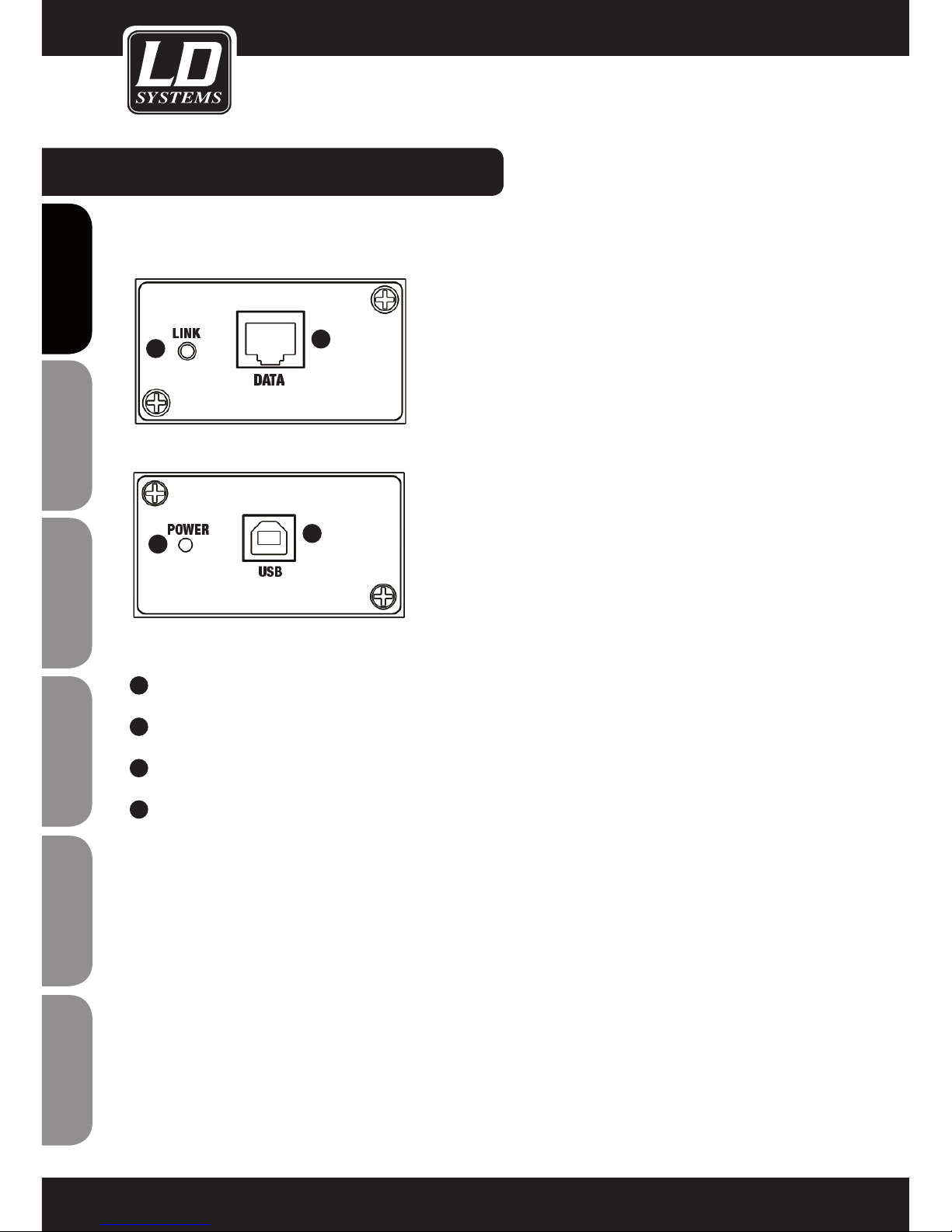
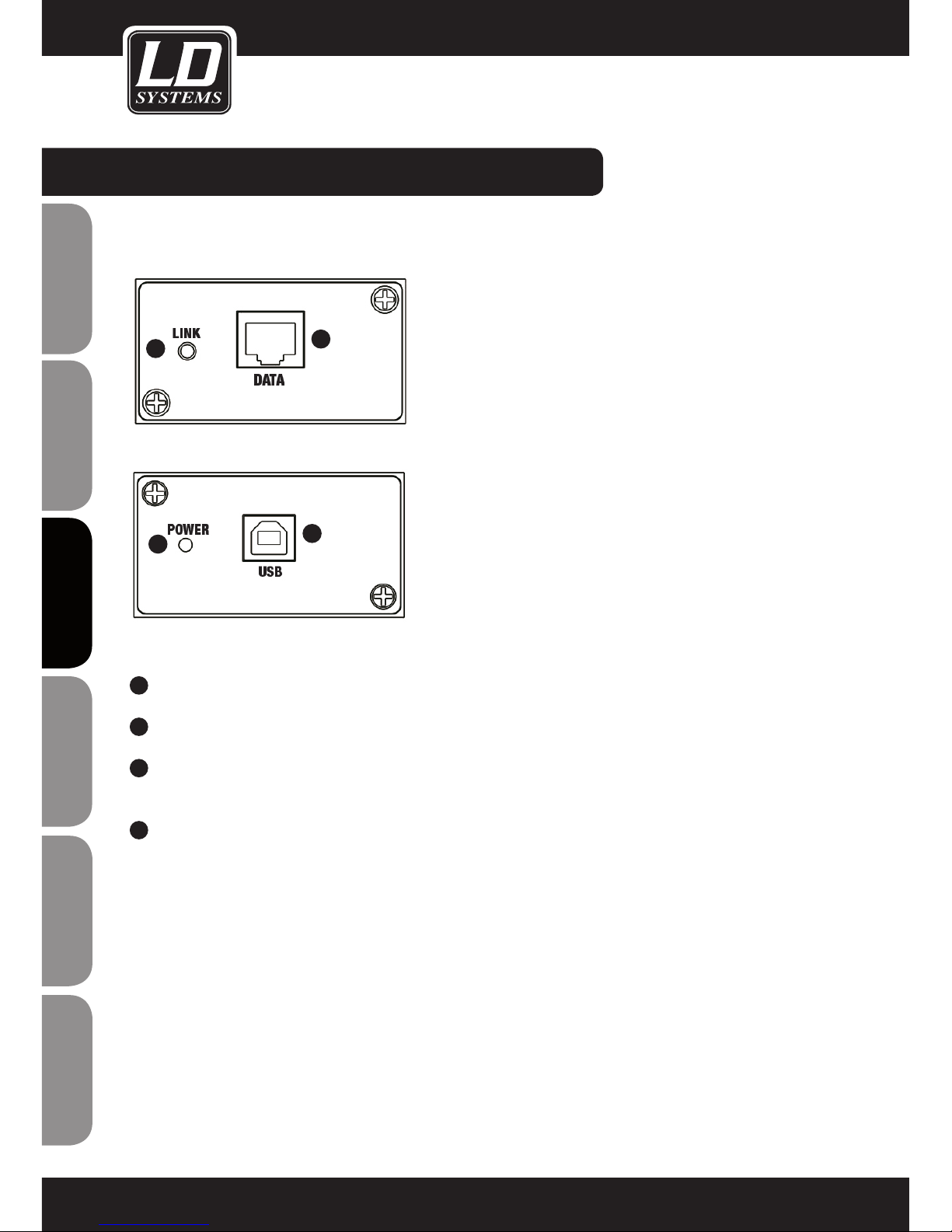
USB TO RS485 CONVERTER:
1
RJ45 PORT, CONNECTION TO THE WIN42HUB
2
USB PORT, CONNECTION TO A WINDOWS PC
3
POWER LED: LIGHTS UP WHEN THE CONVERTER IS CONNECTED CORRECTLY VIA USB.
4
LINK LED: LIGHTS UP WHEN THE CONNECTION BETWEEN CONVERTER AND CONTROLLER
HUB HAS BEEN MADE CORRECTLY.
2
1
4
3
Page 9
9
ITALIANOPOLSKIESPAÑOL
FRANCAISFRANCAIS FRANCAISFRANCAIS
FRANCAISDEUTSCHENGLISH
SOFTWARE INSTALLATION:
SYSTEM REQUIREMENTS
for the WIN42 CONTROL CENTER software and the driver for the WIN42 CONTROLLER HUB: Windows XP,
Windows Vista, Windows 7 and Windows 8, an unused USB 2.0 port, and a recommended monitor resolution of
at least 1366 x 768.
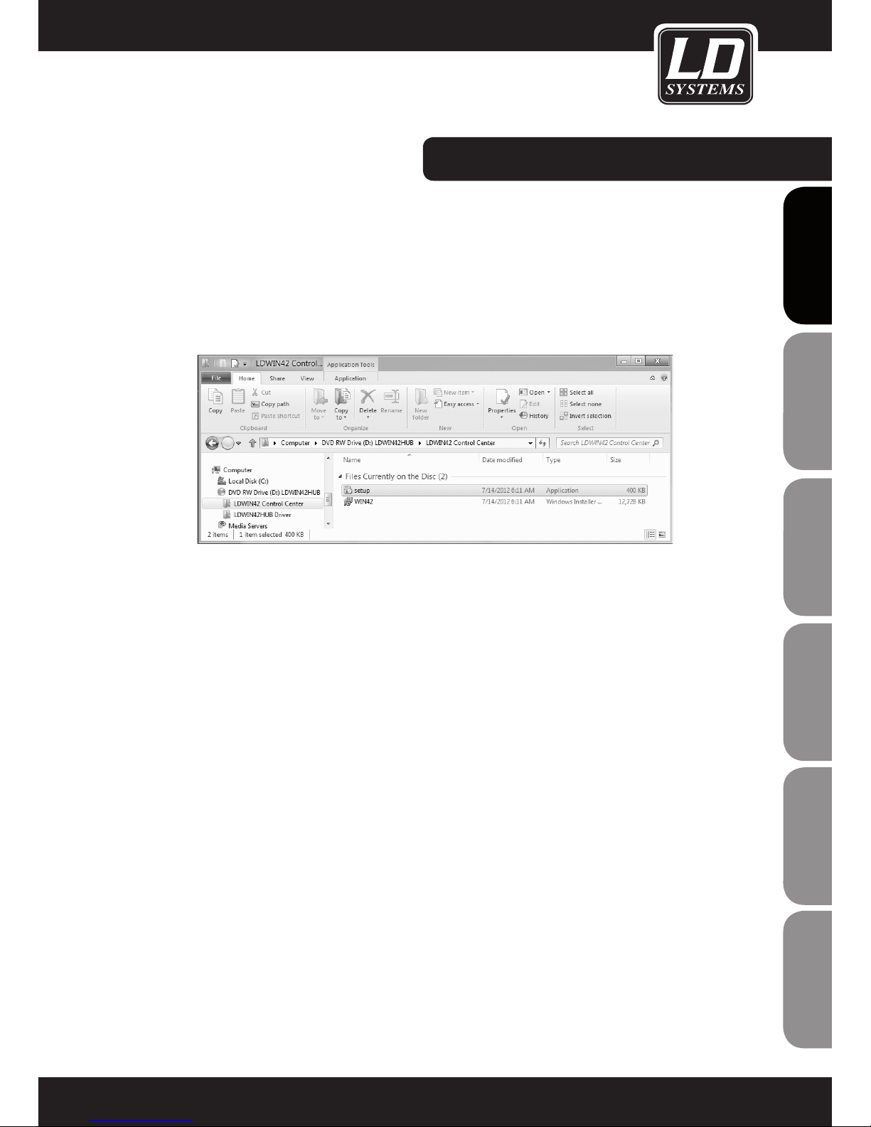
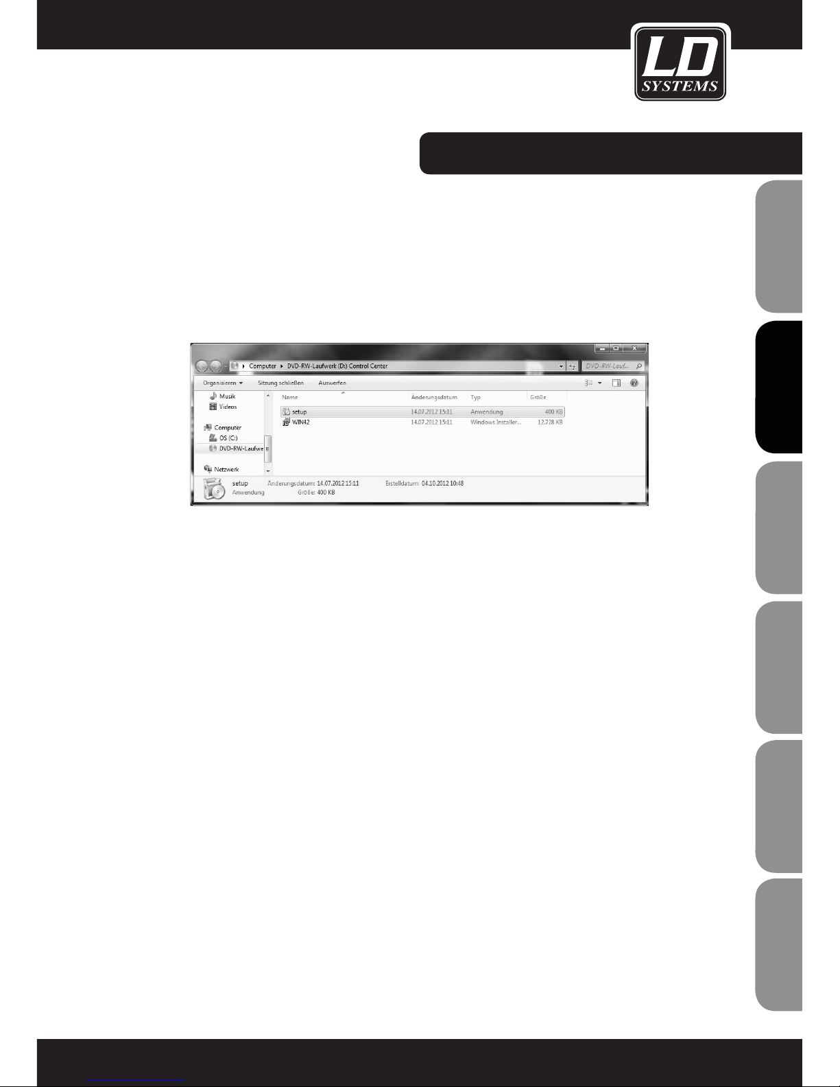
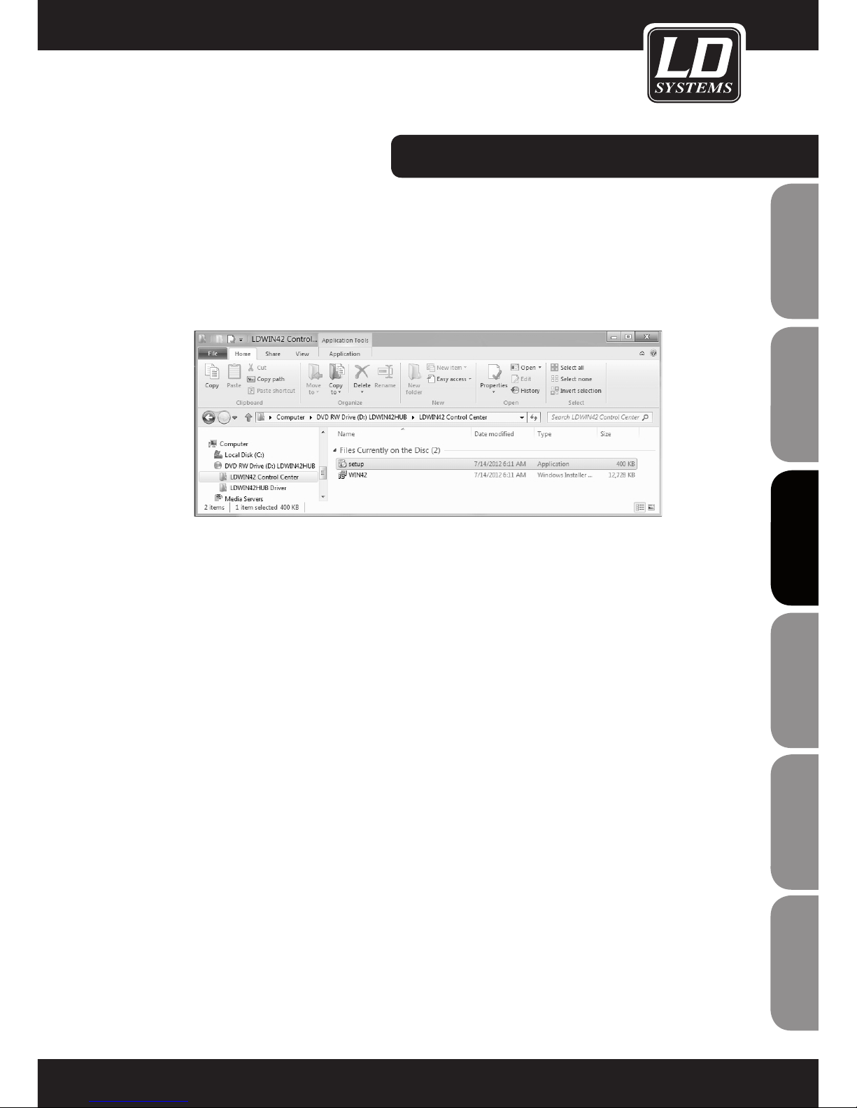
1. Insert the included software CD in the optical drive of your computer, open it, and double-click on the "Setup" file, then follow
the instructions to install the WIN42 CONTROL CENTER software on your computer.
Page 10

10
ENGLISHDEUTSCHFRANCAIS
FRANCAISFRANCAIS FRANCAISFRANCAIS
ESpAñoLpoLSKIITALIANo
SOFTWARE INSTALLATION:
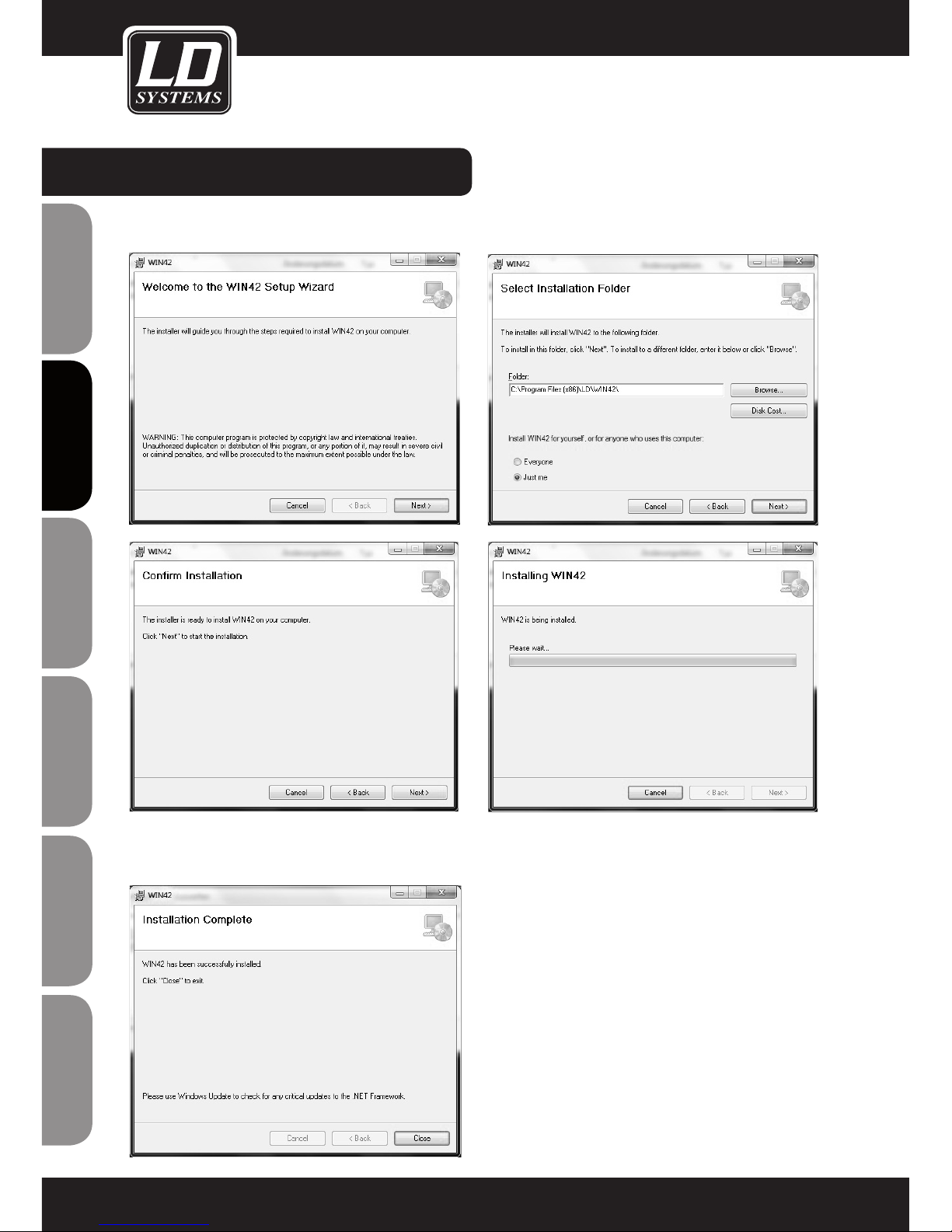
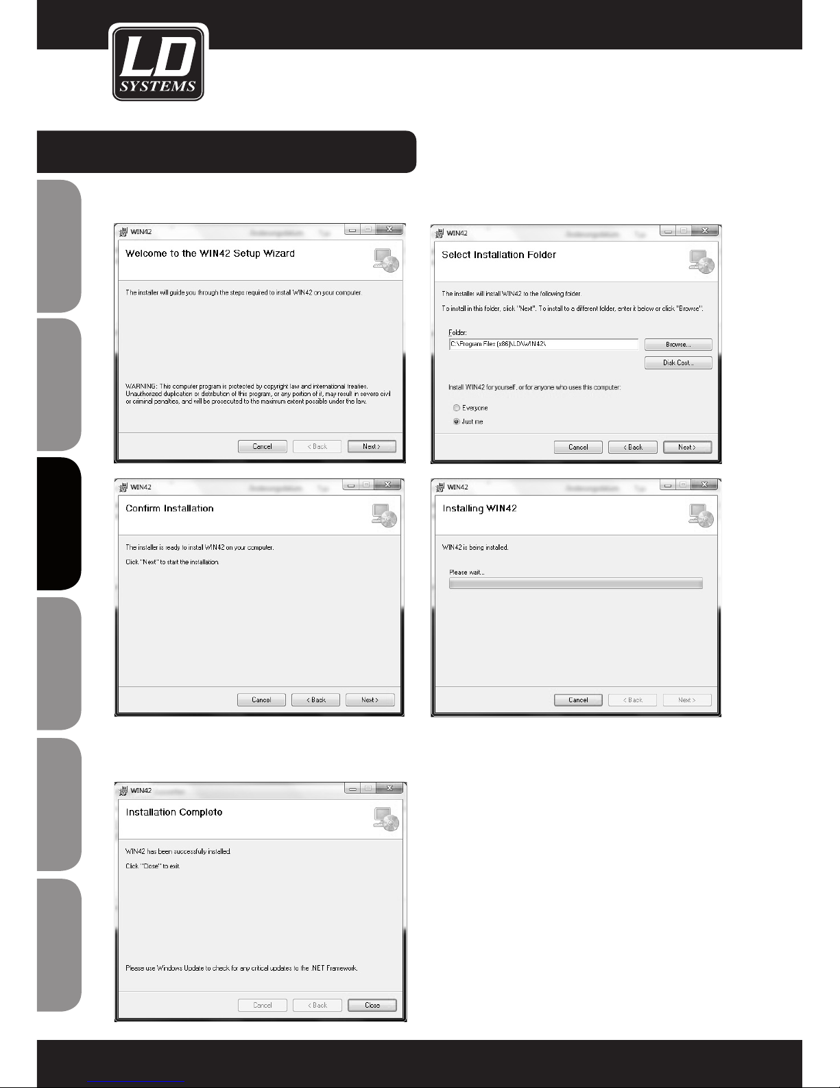
2. You now be prompted to click "Next" multiple times in order to carry out the installation.
Click on "Close" to complete installation.
Page 11

11
ITALIANOPOLSKIESPAÑOL
FRANCAISFRANCAIS FRANCAISFRANCAIS
FRANCAISDEUTSCHENGLISH
Connect the included USB to RS485 converter to an unused USB port on your computer.
DRIVER INSTALLATION:
Page 12

12
ENGLISHDEUTSCHFRANCAIS
FRANCAISFRANCAIS FRANCAISFRANCAIS
ESpAñoLpoLSKIITALIANo
DRIVER INSTALLATION:
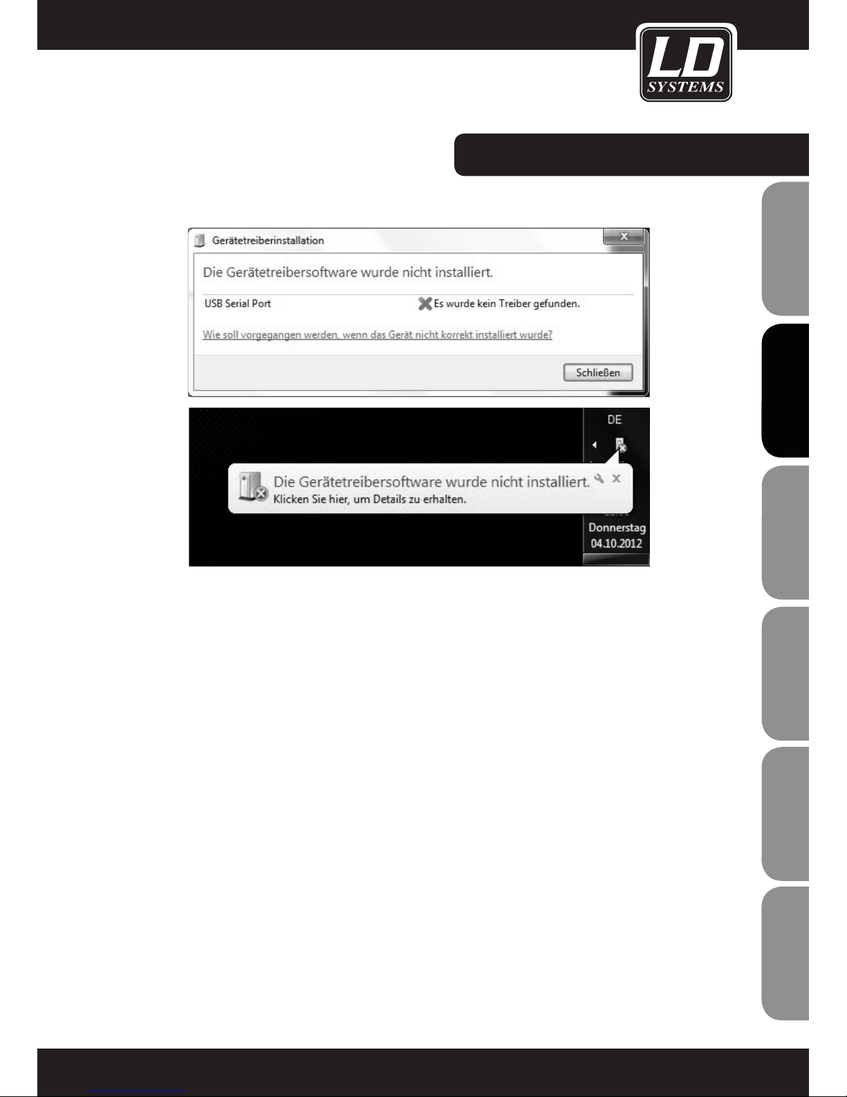
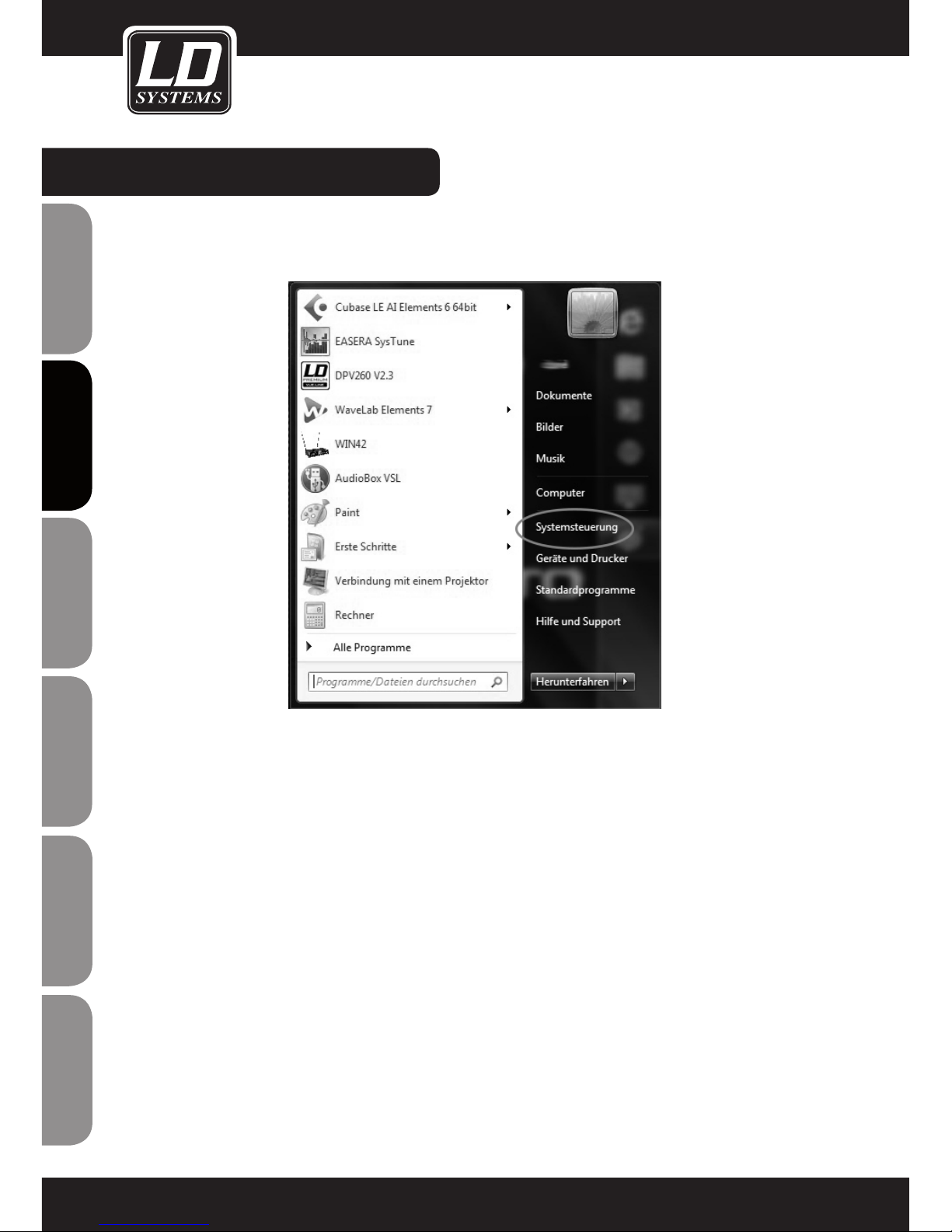
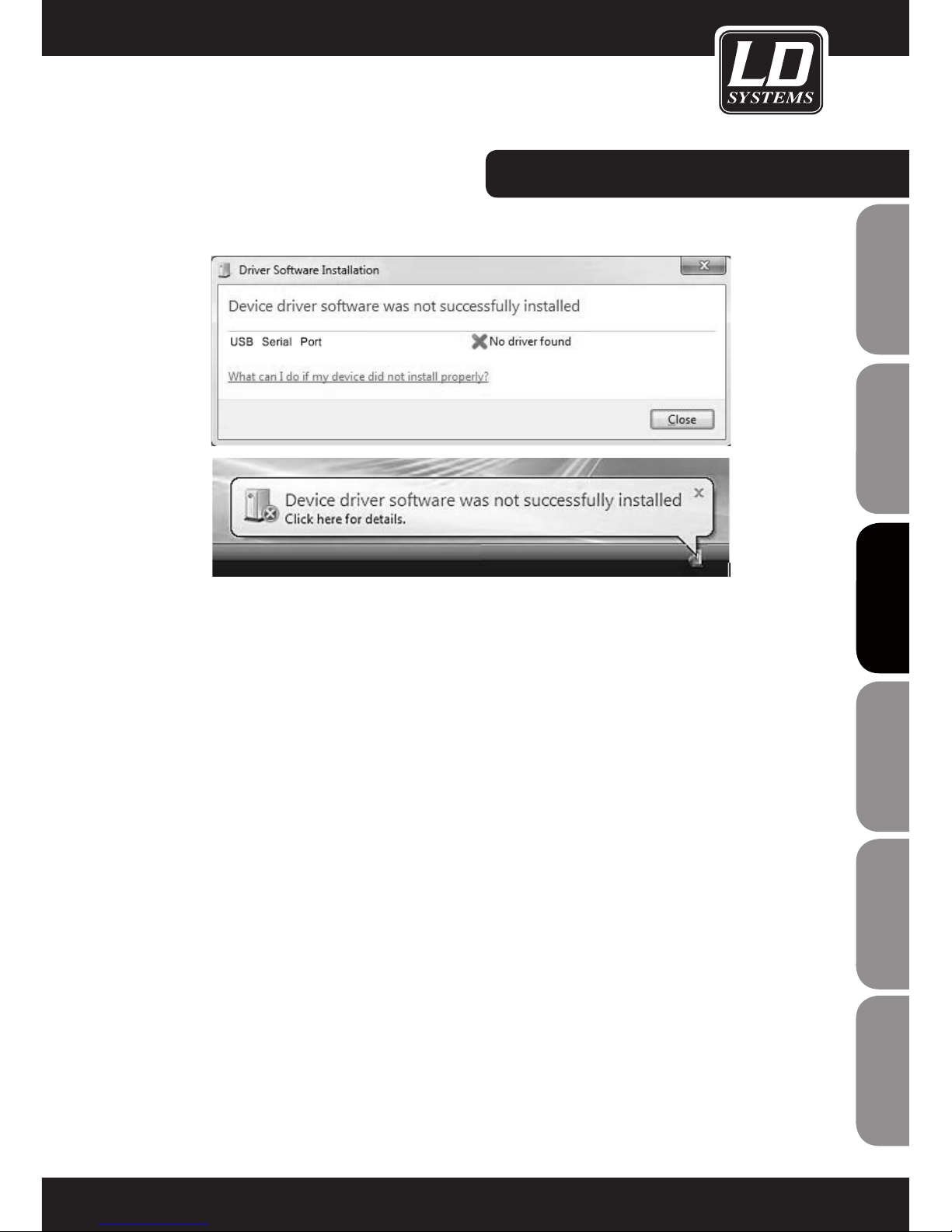
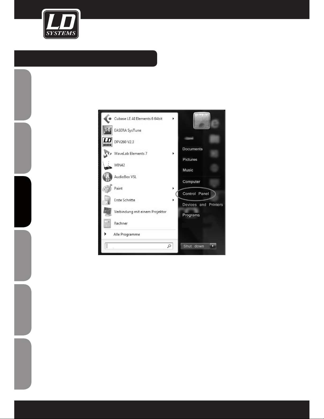
If you see the system messages depicted on the preceding page, install the associated driver by pressing the Windows key on
your keyboard and clicking on "Control Panel".
Page 13

13
ITALIANOPOLSKIESPAÑOL
FRANCAISFRANCAIS FRANCAISFRANCAIS
FRANCAISDEUTSCHENGLISH
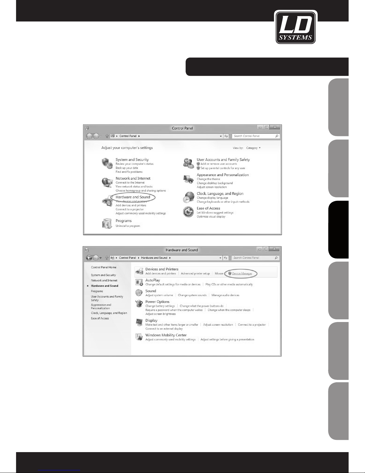
The "Control Panel" window will open. Now click on "Hardware and Sound" and then on "Device Manager".
DRIVER INSTALLATION:
Page 14
14
ENGLISHDEUTSCHFRANCAIS
FRANCAISFRANCAIS FRANCAISFRANCAIS
ESpAñoLpoLSKIITALIANo
DRIVER INSTALLATION:
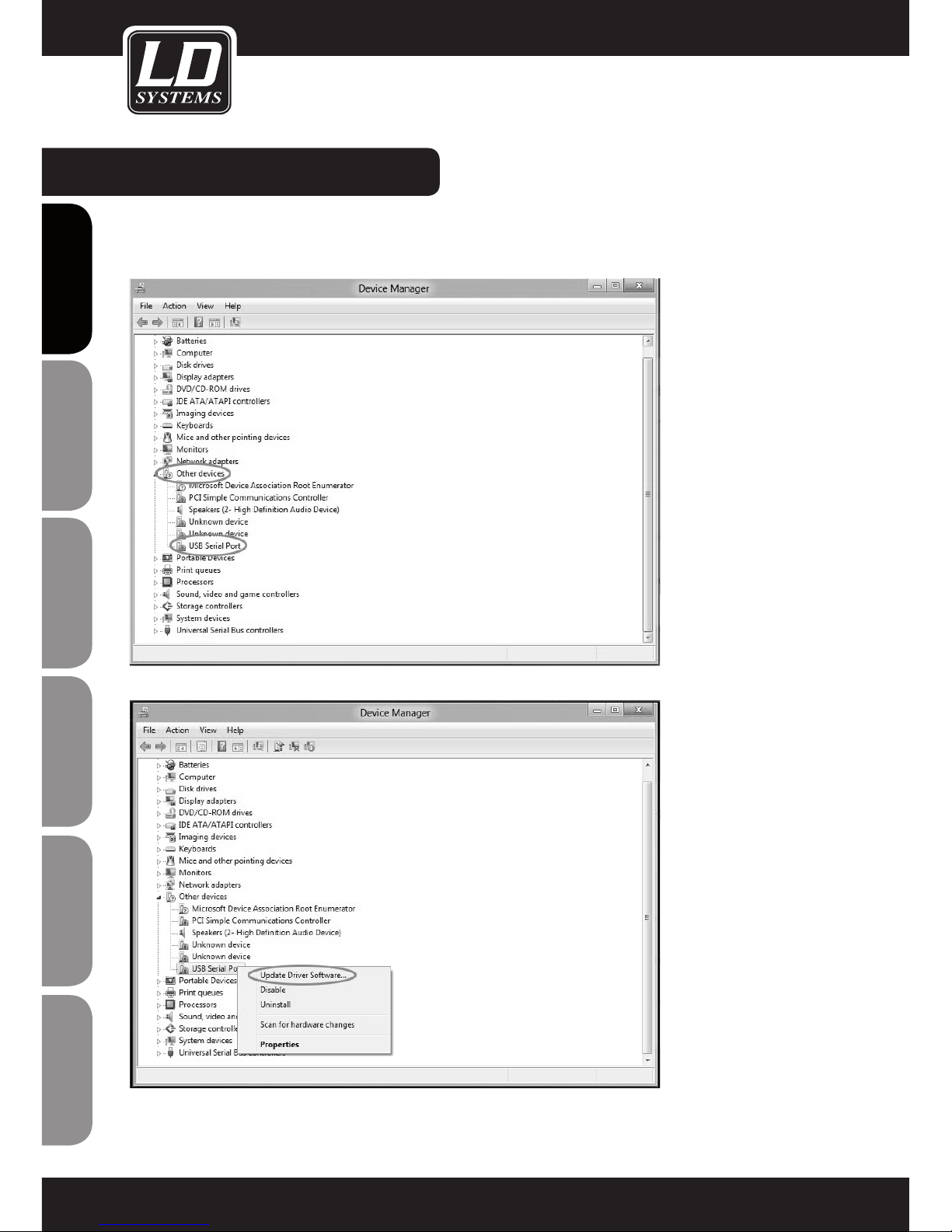
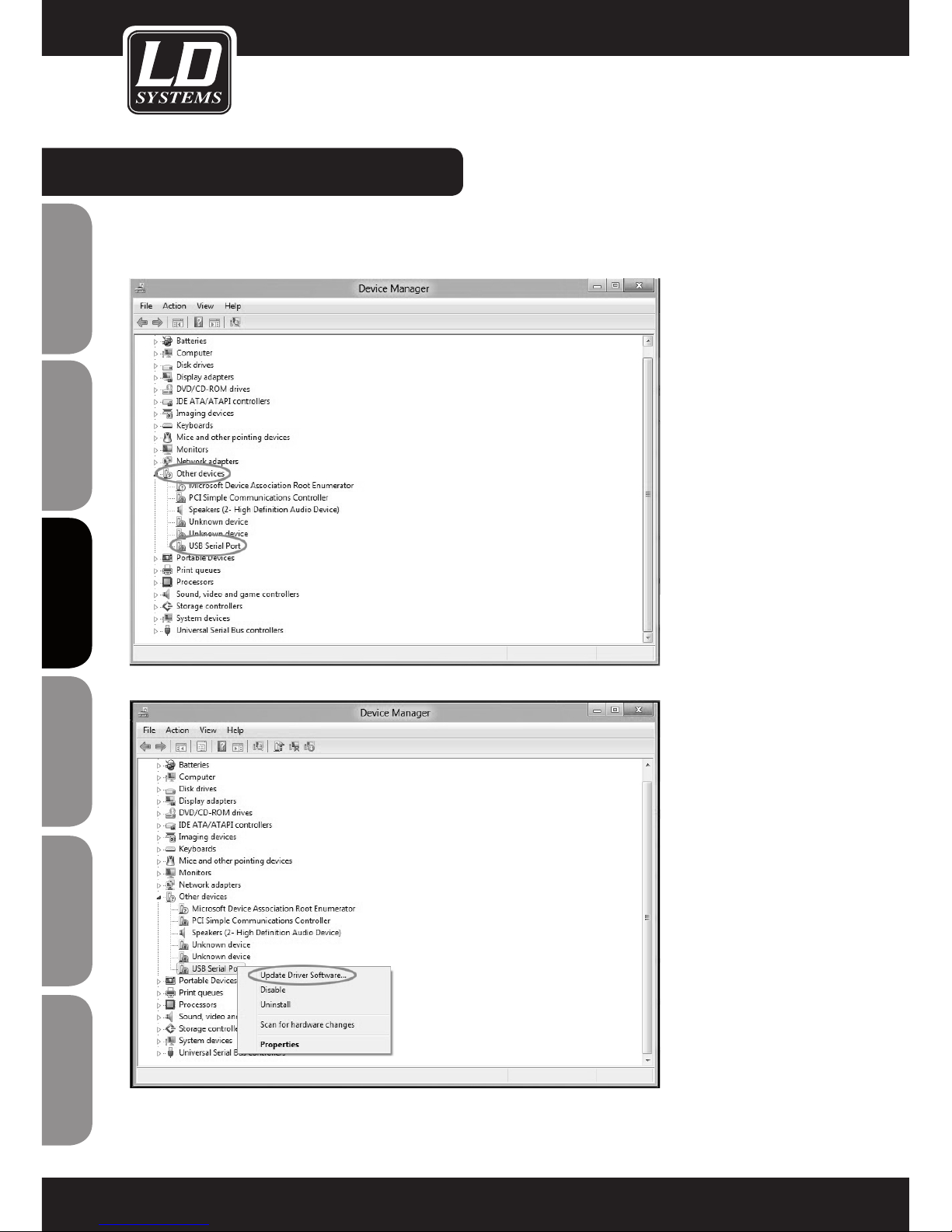
Once the Device Manager window has opened, click on the arrow next to "Other devices". Now click the right mouse button on
"USB serial port" and then click on "Update driver software".
Page 15

15
ITALIANOPOLSKIESPAÑOL
FRANCAISFRANCAIS FRANCAISFRANCAIS
FRANCAISDEUTSCHENGLISH
Now click with the left mouse key on "Browse the computer for driver software".
Select the optical drive of your computer containing the included software and driver CD, click on "Include subfolders", and
continue the process by clicking on "Next".
DRIVER INSTALLATION:
Page 16

16
ENGLISHDEUTSCHFRANCAIS
FRANCAISFRANCAIS FRANCAISFRANCAIS
ESpAñoLpoLSKIITALIANo
DRIVER INSTALLATION:
If the following message appears, click on "Install this driver software anyway".
The driver is now installed. Click on "Close" to exit the installation procedure.
Page 17

17
ITALIANOPOLSKIESPAÑOL
FRANCAISFRANCAIS FRANCAISFRANCAIS
FRANCAISDEUTSCHENGLISH
Now the COM port number of the "USB serial port" will be displayed in Device Manager.
Note: The COM port number of the "USB serial port" must be between 1 and 16.
Now, using the included RJ45 cable, connect the WIN42 CONTROLLER HUB to the USB to RS485 converter and start the WIN42
CONTROL CENTER SOFTWARE. Now select the command "Communication" in the "Tools" menu to see whether the port number
of the USB serial port and the port number in the WIN42 CONTROL CENTER match (COM16 in our example).
DRIVER INSTALLATION:
Page 18

18
ENGLISHDEUTSCHFRANCAIS
FRANCAISFRANCAIS FRANCAISFRANCAIS
ESpAñoLpoLSKIITALIANo
CONNECTING THE WIN42 CONTROLLER HUB:
Note: The cables (16 included in the package contents) for connecting the WIN42 CONTROLLER HUB to the WIN42 receivers have
plugs of two different sizes on each cable. The larger plug is inserted in the COM connector (1 - 16) of the WIN42 CONTROLLER
HUB, while the smaller of the two is plugged into the Data Output connector of the WIN42 receiver.
CHANNEL2
XLR BALANCED
UNBAL
OUTPUT
Data Output
ANTENNA-AANTENNA-B
CHANNEL1
XLR BALANCED
D.C 12-18V
1000mA
UNBAL
OUTPUT
Data Output
CHANNEL2
XLR BALANCED
UNBAL
OUTPUT
Data Output
ANTENNA-AANTENNA-B
CHANNEL1
XLR BALANCED
D.C 12-18V
1000mA
UNBAL
OUTPUT
Data Output
CHANNEL2
XLR BALANCED
UNBAL
OUTPUT
Data Output
ANTENNA-AANTENNA-B
CHANNEL1
XLR BALANCED
D.C 12-18V
1000mA
UNBAL
OUTPUT
Data Output
CHANNEL2
XLR BALANCED
UNBAL
OUTPUT
Data Output
ANTENNA-AANTENNA-B
CHANNEL1
XLR BALANCED
D.C 12-18V
1000mA
UNBAL
OUTPUT
Data Output
1
1
3
5
7
2
4
682345678
USB RS485
DATA CONVERTER
DATA
USB
Page 19

19
ITALIANOPOLSKIESPAÑOL
FRANCAISFRANCAIS FRANCAISFRANCAIS
FRANCAISDEUTSCHENGLISH
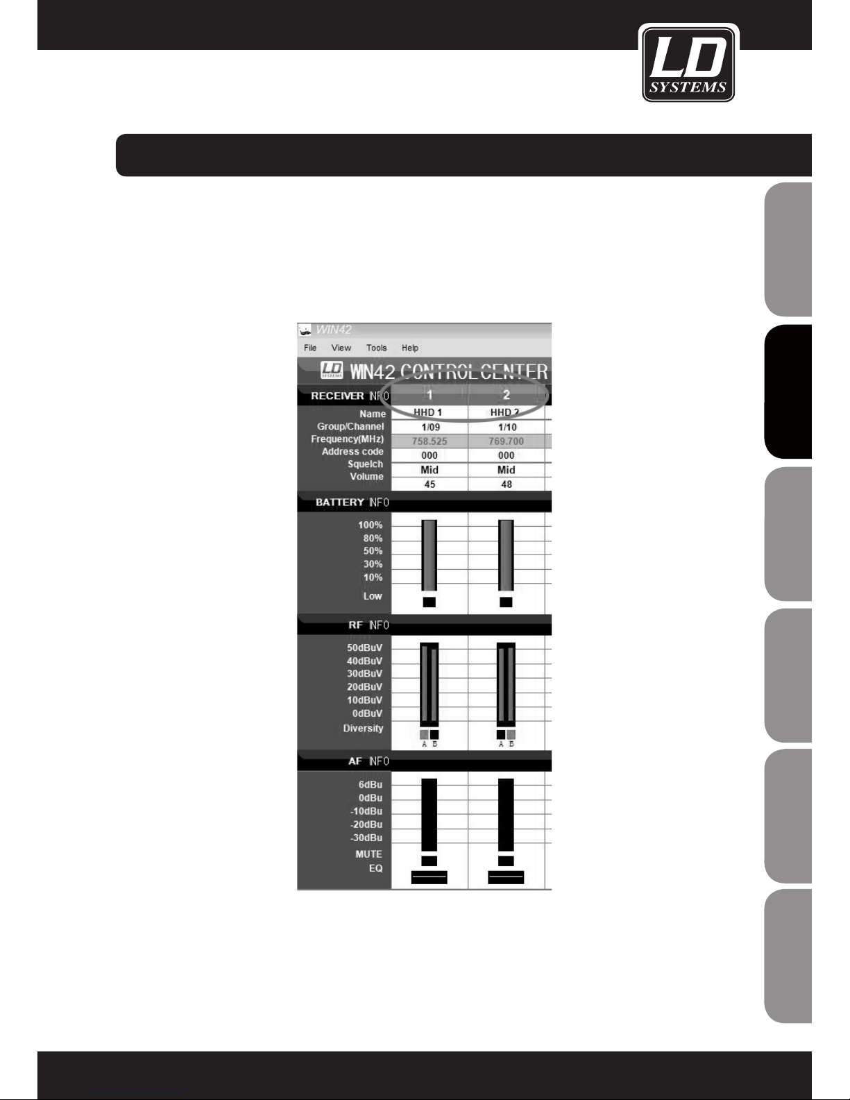
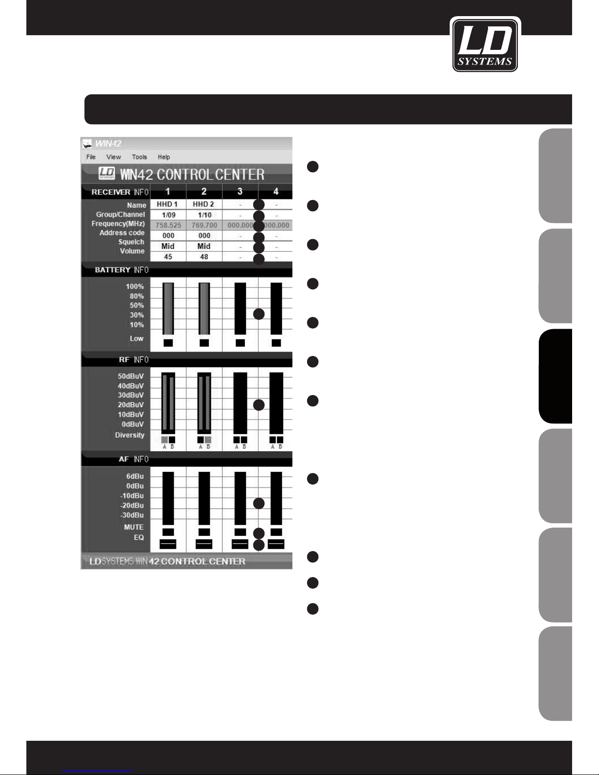
RECEIVER INFO
1
NAME
Click here to assign a name to the receiver
2
GROUP/CHANNEL
Click here to assign the frequency and channel.
3
FREQUENCY
Displays the Group/Channel allocation assigned
under (2)
4
ADDRESS CODE
Click here to assign an address to the receiver
(0-244)
5
SQUELCH
Click here to adjust the squelch setting of the
receiver (Low/Mid/High)
6
RECEIVER VOLUME ADJUSTMENT (03-48)
BATTERY INFO
7
BATTERY STATUS DISPLAY (0-100%)
If the battery status of the transmitter nears a
critical state, the "LOW" indicator lights up.
RF INFO
8
RECEIVER RF FIELD STRENGTH INDICATOR
The active receiver of the diversity system is
indicated by the (A/B) indicators.
AF INFO
9
RECEIVER SIGNAL LEVEL INDICTOR
10
RECEIVER MUTE STATUS INDICATOR
11
EQ
Click here to change the equalizer settings of
the receiver (Flat/Low-cut/Low-cut+High-boost/
High-boost)
USING THE WIN42 CONTROL CENTER SOFTWARE:
1
2
3
4
5
6
7
8
9
10
11
Page 20

20
ENGLISHDEUTSCHFRANCAIS
FRANCAISFRANCAIS FRANCAISFRANCAIS
ESpAñoLpoLSKIITALIANo
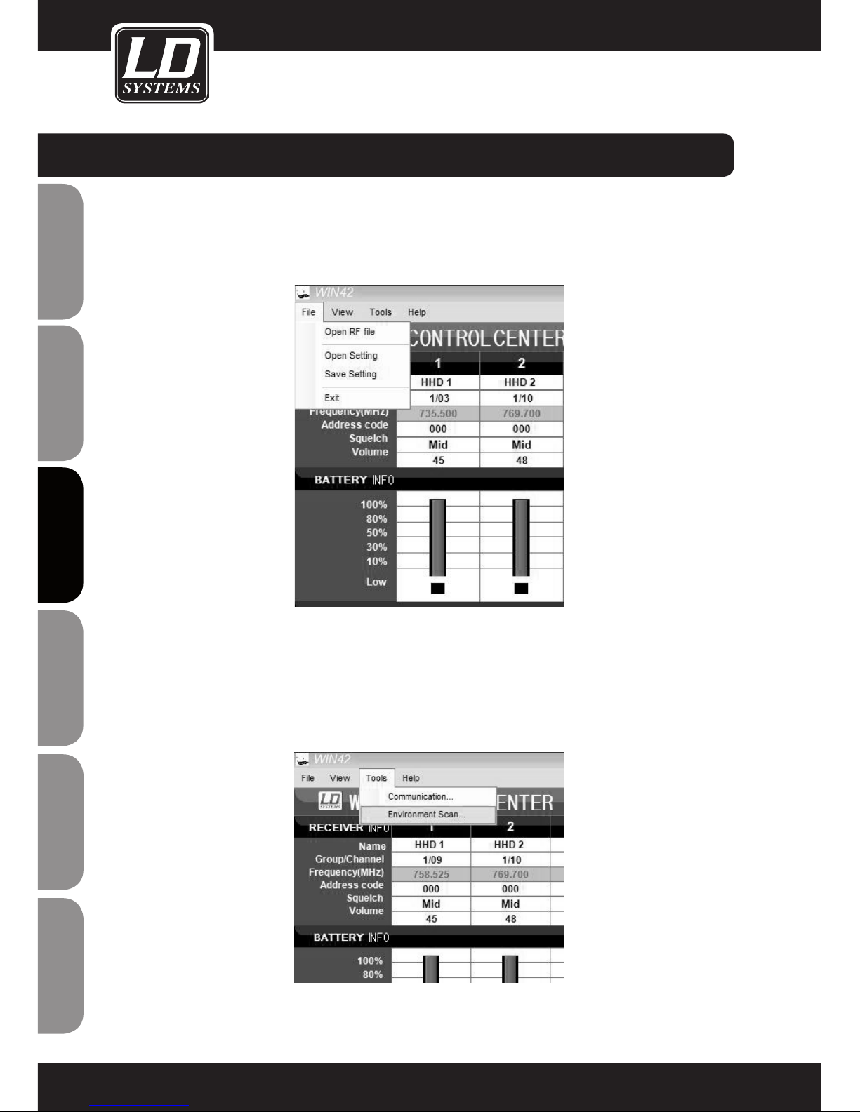
SAVING AND RETRIEVING SETTINGS
All settings that you make in the main window can be saved on your computer and retrieved at a later point in
time.
To do this, select the menu item Open Setting or Save Setting in the File menu in the main window
ENVIRONMENT SCAN
The Environment Scan function lets you scan the entire frequency spectrum of the LD Systems WIN42 system
and find unused frequencies simply and easily.
Please follow these instructions step by step in order to utilize the full scope of functionality of the software.
Select the Environment Scan function in the Tools menu
USING THE WIN42 CONTROL CENTER SOFTWARE:
Page 21

21
ITALIANOPOLSKIESPAÑOL
FRANCAISFRANCAIS FRANCAISFRANCAIS
FRANCAISDEUTSCHENGLISH
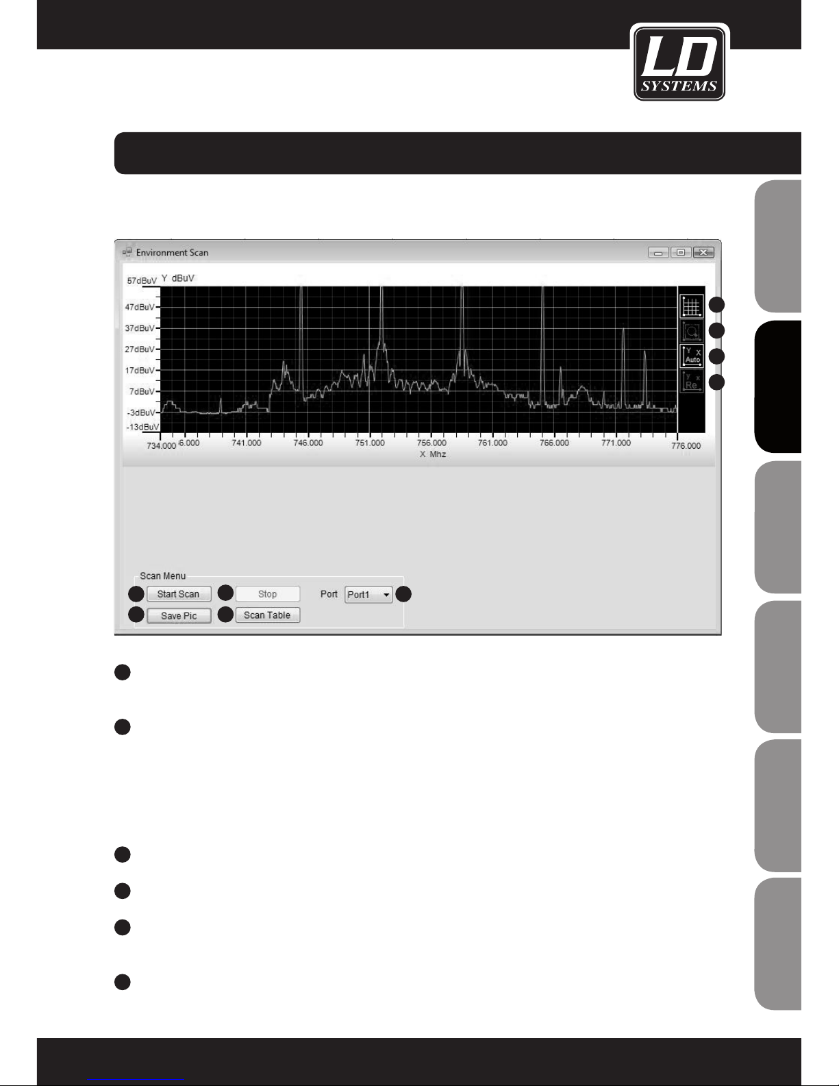
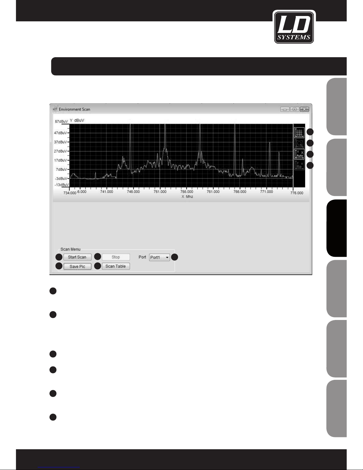
The following functions are available in the Environment Scan window (sample depiction of environment scan)
1
6
7
8
9
3
5
2
4
SCAN MENU
1
PORT
Select the port of one of the connected receivers that is to be used for scanning. Note: This receiver cannot
be used for any other function during scanning.
2
START SCAN
Starts the scanning procedure. The receiver defined in the port selection is used to scan the environment.
The receiver RF field strength is displayed directly in the graph. The entire procedure may take several
minutes.
If the scanning procedure cannot be started, then the message "Scan timeout" appears. In this case, make
certain that the proper port (1) is selected and the receiver is correctly connected and working.
3
STOP
Stops the scanning procedure.
4
SAVE PIC
Click here to save the scan results as a graphics file (*.jpg) on your computer.
5
SCAN TABLE
Click here to view the scan results in tabular form and allocate unused frequencies to the connected
receivers. See also the section "Scan Table".
6
SHOW GRID
Toggles the coordinate grid in the display on and off.
USING THE WIN42 CONTROL CENTER SOFTWARE:
Page 22

22
ENGLISHDEUTSCHFRANCAIS
FRANCAISFRANCAIS FRANCAISFRANCAIS
ESpAñoLpoLSKIITALIANo
7
ZOOM IN
Click here to zoom in on a section of the scan results. Use the mouse to mark the area to be enlarged.
8
AUTO COORDINATE
Click here to toggle the automatic adjustment of the coordinates on or off.
9
DEFAULT COORDINATE
Click her to leave the zoom view and return to the default view.
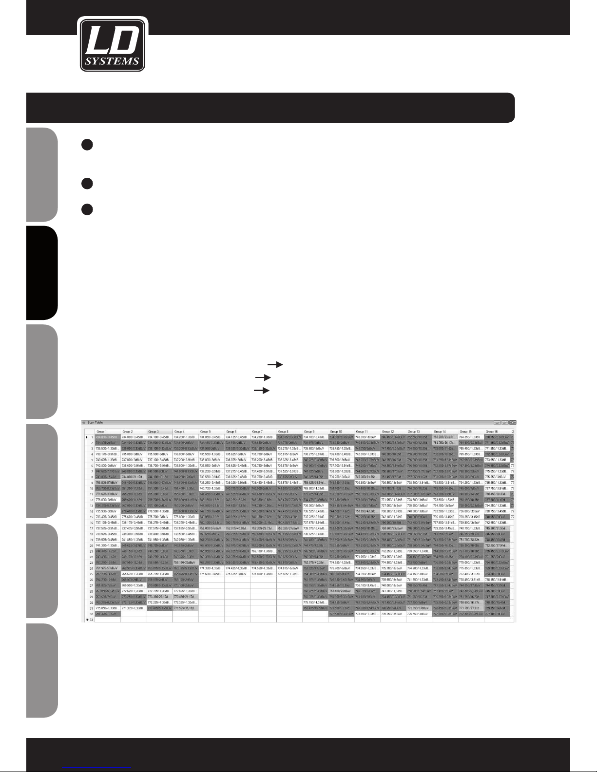
SCAN TABLE
(Sample depiction of scan table)
In this view, you can find frequencies and assign them to the connected receivers.
Carry out the environment scan as described above and click on Scan Table to view the scan results in tabular
form. Here you will find all available frequency groups with the associated frequencies. The results of the
environment scan are shown for each frequency as the value of the measured field strength. The available
frequencies in the desired group are also identified by coloured markings.
White: Receiver field strength 0dBuV or less unused frequency
Yellow: receiver field strength 0dBuV to 20dBuV frequency possibly in use
Red: Receiver field strength 20dBuV or greater frequency in use
To be able to access the results at a later point in time, save the scan table by clicking on the Save button at the
lower right edge of the screen.
To open a previously saved scan table , select the menu item Open RF File in the File menu in the main menu.
FREQUENCY ALLOCATION
Double-click on a frequency that you want to assign to one of the connected receivers. Afterwards, you will be
returned to the main screen automatically.
USING THE WIN42 CONTROL CENTER SOFTWARE:
Page 23

23
ITALIANOPOLSKIESPAÑOL
FRANCAISFRANCAIS FRANCAISFRANCAIS
FRANCAISDEUTSCHENGLISH
The blinking of the receiver number indicates to which receiver the selected frequency can be assigned. Select
a receiver by clicking on the corresponding receiver number. The selected frequency from the scan table will be
assigned to the desired receiver.
Repeat this operation until frequencies have been allocated to all available receivers. To synchronize the
receivers that you have now programmed with their transmitters, use the sync function of the receiver or set the
frequency manually at the transmitter.
USING THE WIN42 CONTROL CENTER SOFTWARE:
Page 24

24
ENGLISHDEUTSCHFRANCAIS
FRANCAISFRANCAIS FRANCAISFRANCAIS
ESpAñoLpoLSKIITALIANo
Product type Controller for WIN42 wireless systems
Type software-based
Number of supported wireless systems 16
Indicators 16 x LED activation indicator
Operating voltage 9 V - 18 V DC, 300 mA
Width 482 mm
Height 44 mm
Depth 160 mm
Weight 1850 g
Included accessories USB to RS485 converter, 1 x USB cable, 16 x RJ11 cable, 1 x RJ45 cable, 1 x
power adapter, software CD
SPECIFICATIONS:
Page 25

25
ITALIANOPOLSKIESPAÑOL
FRANCAISFRANCAIS FRANCAISFRANCAIS
FRANCAISDEUTSCHENGLISH
LIMITED WARRANTY
This Limited Warranty applies to the Adam Hall, LD Systems, LD Premium, Defender, Palmer, Cameo and Eminence
branded products.
The statutory warranty rights towards the seller are not affected by this guarantee. In fact, it justifies, additional
independent warranty claims towards Adam Hall.
Adam Hall warrants that the Adam Hall product you have purchased from Adam Hall or from an Adam Hall authorized reseller is free from defects in materials or workmanship under normal use for a period of 2 or 5 years from
the date of purchase.
The Limited Warranty Period starts on the date of purchase. In order to receive warranty services you are required
to provide proof of the purchase date. Your dated sales or delivery receipt, showing the date of purchase, is your
proof of the purchase date. Should products of the brands named above be in need of repair within the limited warranty period, you are entitled to warranty services according to the terms and conditions stated in this document.
This Limited Warranty extends only to the original purchaser of this Adam Hall branded product and is not transferable to anyone who obtains ownership of the Adam Hall branded product from the original purchaser. During
the Limited Warranty Period, Adam Hall will repair or replace the defective component parts or the product. All
component parts or hardware products removed under this Limited Warranty become the property of Adam Hall.
In the unlikely event that your Adam Hall product has a recurring failure, Adam Hall, at its discretion, may elect to
provide you with a replacement unit of Adam Hall´s choice that is at least equivalent to your Adam Hall branded
product in hardware performance.
Adam Hall does not warrant that the operation of this product will be uninterrupted or error-free. Adam Hall is not
responsible for damage that occurs as a result of your failure to follow the instructions included with the Adam
Hall branded product.
This Limited Warranty does not apply,
- to wear parts (e.g. accumulator)
- to any product from which the serial number has been removed or that has been damaged or rendered defective as the result of an accident
- in case of, misuse, abuse, or other external causes
- by operation outside the usage parameters stated in the user´s documentation shipped with the product by use
of spare parts not manufactured or sold by Adam Hall
- by modification or service by anyone other than Adam Hall
These terms and conditions constitute the complete and exclusive warranty agreement between you and Adam
Hall regarding the Adam Hall branded product you have purchased.
MANUFACTURER´S DECLARATIONS:
Page 26

26
ENGLISHDEUTSCHFRANCAIS
FRANCAISFRANCAIS FRANCAISFRANCAIS
ESpAñoLpoLSKIITALIANo
MANUFACTURER´S DECLARATIONS:
LIMITATION OF LIABILITY
If your Adam Hall branded hardware product fails to work as warranted above, your sole and exclusive remedy
shall be repair or replacement. Adam Halls’ maximum liability under this limited warranty is expressly limited
to the lesser of the price you have paid for the product or the cost of repair or replacement of any hardware
components that malfunction in conditions of normal use.
Adam Hall is not liable for any damages caused by the product or the failure of the product, including any lost
profits or savings or special, incidental, or consequential damages. Adam Hall is not liable for any claim made by
a third party or made by you for a third party.
This limitation of liability applies whether damages are sought, or claims are made, under this Limited Warranty
or as a tort claim (including negligence and strict product liability), a contract claim, or any other claim. This limitation of liability cannot be waived or amended by any person. This limitation of liability will be effective even if
you have advised Adam Hall of an authorized representative of Adam Hall of the possibility of any such damages.
This limitation of liability however, will not apply to claims for personal injury.
This Limited Warranty gives you specific legal rights. You may also have other rights that may vary from state to
state or from country to country. You are advised to consult applicable state or country laws for a full determination of your rights.
REQUESTING WARRANTY-SERVICE
To request warranty service for the product, contact Adam Hall or the Adam Hall authorized reseller from which
you purchased the product.
EC DECLARATION OF CONFORMITY
These devices meet the essential requirements and further relevant specifications of Directives 2004/108/EC
(EMC) and 2006/95/EC (LVD). For more information, see www.adamhall.com.
CORRECT DISPOSAL OF THIS PRODUCT (ELECTRICAL WASTE)
(Applicable in the European Union and other European countries with separate collection systems)
This marking shown on the product or its literature, indicates that it should not be disposed with other household
wastes at the end of its working life. To prevent possible harm to the environment or human health from uncontrolled waste disposal, please separate this from other types of wastes and recycle it responsibly to promote the
sustainable reuse of material resources.
Household users should contact either the retailer where they purchased this product, or their local government
office, for details on where and how they can recycle this item in an enviromentally friendly manner.
Business users should contact their supplier and check the terms and conditions of the purchase contract. This
product should not be mixed with other commercial wastes for disposal.
Page 27

27
ITALIANOPOLSKIESPAÑOL
FRANCAISFRANCAIS FRANCAISFRANCAIS
FRANCAISDEUTSCHENGLISH
WEEE-DECLARATION
Your LD-Systems product was developed and manufactured with high quality materials and components wich
can be recycled and/or reused. This symbol indicates that electrical and electronic equipment must be disposed
of separately from normal waste at the end of its operational lifetime.
Please dispose of this product by bringing it to your local collection point or recycling centre for such equipment.
This will help to protect the environment in which we all live.
BATTERIES AND ACCUMULATORS
The supplied batteries or rechargeable batteries can be recycled. Please dispose of them as special waste or
return them to your specialist dealer. In order to protect the environment, only dispose exhausted batteries.
ECOLOGY AND ENERGY SAVING
Saving electric energy helps to protect the environment. Please turn off all electrical equipment when it is not in
use. To avoid power consumption in idle mode, disconnect all electrical equipment from mains when not in use.
Adam Hall GmbH, all rights reserved. The technical data and the functional product characteristics can be subject
to modifications. The photocopying, the translation, and all other forms of copying of fragments or of the integrality of this user’s manual is prohibited.
MANUFACTURER´S DECLARATIONS:
Page 28

ENGLISHDEUTSCHFRANCAIS
FRANCAISFRANCAIS FRANCAISFRANCAIS
ESpAñoLpoLSKIITALIANo
28
Sie haben die richtige Wahl getroffen!
Dieses Gerät wurde unter hohen Qualitätsanforderungen entwickelt und gefertigt, um viele Jahre einen reibungslosen Betrieb zu gewährleisten. Dafür steht LD Systems mit seinem Namen und der langjährigen Erfahrung als
Hersteller hochwertiger Audioprodukte.
Bitte lesen Sie diese Bedienungsanleitung sorgfältig, damit Sie Ihr neues Produkt von LD Systems schnell optimal
einsetzen können.
Mehr Informationen zu LD-SYSTEMS finden Sie auf unserer Internetseite WWW.LD-SYSTEMS.COM
Einführung
Der LD Systems WIN42HUB und die dazugehörige Software WIN42 CONTROL CENTER bietet Ihnen die
Möglichkeit, bis zu 16 WIN42 Funkstrecken zu überwachen und zu steuern. In übersichtlichen Grafiken haben
Sie Funkfrequenz, Batteriestatus, Funksignal, Audiopegel und vieles mehr jeder einzelnen angeschlossenen
WIN42 Funkstrecke unter Kontrolle. Darüber hinaus bietet die Software einen "Environment Scan" mit dessen
Hilfe der jeweilige Standort nach freien Empfangsfrequenzen abgesucht werden kann.
Page 29

ITALIANOPOLSKIESPAÑOL
FRANCAISFRANCAIS FRANCAISFRANCAIS
FRANCAISDEUTSCHENGLISH
29
POWER
WIN42 CONTROLLER HUB
COM
LD WIN42HUB
WIN42HUB
Page 30

ENGLISHDEUTSCHFRANCAIS
FRANCAISFRANCAIS FRANCAISFRANCAIS
ESpAñoLpoLSKIITALIANo
30
SICHERHEITSHINWEISE:
1. Lesen Sie diese Anleitung bitte sorgfältig durch.
2. Bewahren Sie alle Informationen und Anleitungen an einem sicheren Ort auf.
3. Befolgen Sie die Anweisungen.
4. Beachten Sie alle Warnhinweise. Entfernen Sie keine Sicherheitshinweise oder andere Informationen vom Gerät.
5. Verwenden Sie das Gerät nur in der vorgesehenen Art und Weise.
6. Verwenden Sie ausschließlich stabile und passende Stative bzw. Befestigungen (bei Festinstallationen). Stellen
Sie sicher, dass Wandhalterungen ordnungsgemäß installiert und gesichert sind. Stellen Sie sicher, dass das
Gerät sicher installiert ist und nicht herunterfallen kann.
7. Beachten Sie bei der Installation die für Ihr Land geltenden Sicherheitsvorschriften.
8. Installieren und betreiben Sie das Gerät nicht in der Nähe von Heizkörpern, Wärmespeichern, Öfen oder
sonstigen Wärmequellen. Sorgen Sie dafür, dass das Gerät immer so installiert ist, dass es ausreichend gekühlt
wird und nicht überhitzen kann.
9. Platzieren Sie keine Zündquellen wie z.B. brennende Kerzen auf dem Gerät.
10. Lüftungsschlitze dürfen nicht blockiert werden.
11. Betreiben Sie das Gerät nicht in unmittelbarer Nähe von Wasser. Bringen Sie das Gerät nicht mit brennbaren
Materialien, Flüssigkeiten oder Gasen in Berührung.
12. Sorgen Sie dafür, dass kein Tropf- oder Spritzwasser in das Gerät eindringen kann. Stellen Sie keine mit
Flüssigkeit gefüllten Behältnisse wie Vasen oder Trinkgefäße auf das Gerät.
13. Sorgen Sie dafür, dass keine Gegenstände in das Gerät fallen können.
14. Betreiben Sie das Gerät nur mit dem vom Hersteller empfohlenen und vorgesehenen Zubehör.
15. ACHTUNG: Wenn das Netzkabel des Geräts mit einem Schutzkontakt ausgestattet ist, muss es an einer
Steckdose mit Schutzleiter angeschlossen werden. Deaktivieren Sie niemals den Schutzleiter eines Netzkabels.
16. Schalten Sie das Gerät nicht sofort ein, wenn es starken Temperaturschwankungen ausgesetzt war (beispielsweise nach dem Transport). Feuchtigkeit und Kondensat könnten das Gerät beschädigen. Schalten Sie das
Gerät erst ein, wenn es Zimmertemperatur erreicht hat.
17. Öffnen Sie das Gerät nicht und verändern Sie es nicht.
18. Bevor Sie das Gerät an die Steckdose anschließen, prüfen Sie zuerst, ob die Spannung und die Frequenz
des Stromnetzes mit den auf dem Gerät angegebenen Werten übereinstimmen. Verfügt das Gerät über einen
Spannungswahlschalter, schließen Sie das Gerät nur an die Steckdose an, wenn die Gerätewerte mit den Werten
des Stromnetzes übereinstimmen.
Wenn das mitgelieferte Netzkabel bzw. der mitgelieferte Netzadapter nicht in Ihre Netzsteckdose passt, wenden
Sie sich an Ihren Elektriker.
19. Treten Sie nicht auf das Netzkabel. Sorgen Sie dafür, dass spannungsführende Kabel speziell an der Netzbuchse bzw. am Netzadapter und der Gerätebuchse nicht geknickt werden.
20. Überprüfen Sie nach dem Anschluss des Geräts alle Kabelwege, um Schäden oder Unfälle, z. B. durch
Stolperfallen zu vermeiden.
21. Achten Sie bei der Verkabelung des Geräts immer darauf, dass das Netzkabel bzw. der Netzadapter stets frei
zugänglich ist. Trennen Sie das Gerät stets von der Stromzuführung, wenn das Gerät nicht benutzt wird, oder Sie
das Gerät reinigen möchten.
Ziehen Sie Netzkabel und Netzadapter immer am Stecker bzw. am Adapter und nicht am Kabel aus der Steckdose. Berühren Sie Netzkabel und Netzadapter niemals mit nassen Händen.
22. Schalten Sie das Gerät möglichst nicht schnell hintereinander ein und aus, da sonst die Lebensdauer des
Geräts beeinträchtigt werden könnte.
Page 31
ITALIANOPOLSKIESPAÑOL
FRANCAISFRANCAIS FRANCAISFRANCAIS
FRANCAISDEUTSCHENGLISH
31
ENGLISH
ITALIANOPOLSKIESPAÑOL
FRANCAISFRANCAIS
FRANCAISDEUTSCH
31
23. WICHTIGER HINWEIS: Ersetzen Sie Sicherungen ausschließlich durch Sicherungen des gleichen Typs
und Werten. Sollte eine Sicherung wiederholt auslösen, wenden Sie sich bitte an ein autorisiertes Servicezentrum.
24. Um das Gerät vollständig vom Stromnetz zu trennen, entfernen Sie das Netzkabel bzw. den Netzadapter aus
der Steckdose.
25. Wenn Ihr Gerät mit einem Volex-Netzanschluss bestückt ist, muss der passende Volex-Gerätestecker
entsperrt werden, bevor er entfernt werden kann. Das bedeutet aber auch, dass das Gerät durch eine Ziehen
am Netzkabel verrutschen und herunterfallen kann, wodurch Personen verletzt werden und/oder andere Schäden
auftreten können. Verlegen Sie Ihre Kabel daher immer sorgfältig.
26. Entfernen Sie Netzkabel und Netzadapter aus der Steckdose bei Gefahr eines Blitzschlags oder wenn Sie das
Gerät länger nicht verwenden.
27. Achten Sie beim Transport darauf, dass das Gerät nicht herunterfallen und dabei möglicherweise Sach- und
Personenschäden verursachen kann.
28. Wenn Ihr Gerät nicht mehr ordnungsgemäß funktioniert, Flüssigkeiten oder Gegenstände in das Geräteinnere gelangt sind, oder das Gerät anderweitig beschädigt wurde, schalten Sie es sofort aus und trennen es von
der Netzsteckdose. Dieses Gerät darf nur von autorisiertem Fachpersonal repariert werden.
29. Verwenden Sie zur Reinigung des Geräts ein trockenes Tuch.
30. Beachten Sie alle in Ihrem Land geltenden Entsorgungsgesetze. Trennen Sie bei der Entsorgung bitte Kunststoff und Papier bzw. Kartonagen voneinander.
31. Kunststoffbeutel müssen außer Reichweite von Kindern aufbewahrt werden.
CAUTION
RISK OF ELECTRIC SHOCK
DO NOT OPEN
ACHTUNG:
Entfernen Sie niemals die Abdeckung, da sonst das Risiko eines elektrischen Schlages besteht. Im Inneren des
Geräts befinden sich keine Teile, die vom Bediener repariert oder gewartet werden können. Lassen Sie Reparaturen ausschließlich von qualifiziertem Service-Personal durchführen.
Das gleichschenkelige Dreieck mit dem Blitzsymbol kennzeichnet
nicht-isolierte, „gefährliche“ Spannungen im Gerät,
die einen für die Gesundheit gefährlichen Stromschlag verursachen können.
Das gleichschenkelige Dreieck mit dem Ausrufezeichen kennzeichnet wichtige Bedienungs- und
Wartungshinweise.
ACHTUNG! HOHE LAUTSTÄRKEN!
Dieses Gerät ist für den professionellen Einsatz vorgesehen. Der kommerzielle Betrieb dieses Geräts unterliegt
den jeweils gültigen nationalen Vorschriften und Richtlinien zur Unfallverhütung. Als Hersteller ist Adam Hall
gesetzlich verpflichtet, Sie ausdrücklich auf mögliche Gesundheitsrisiken hinzuweisen.
Gehörschäden durch hohe Lautstärken und Dauerbelastung: Bei der Verwendung dieses Produkts können hohe
Schalldruckpegel (SPL) erzeugt werden, die bei Künstlern, Mitarbeitern und Zuschauern zu irreparablen Gehörschäden führen können. Vermeiden Sie länger anhaltende Belastung durch hohe Lautstärken über 90 dB.
Page 32
ENGLISHDEUTSCHFRANCAIS
FRANCAISFRANCAIS FRANCAISFRANCAIS
ESpAñoLpoLSKIITALIANo
32
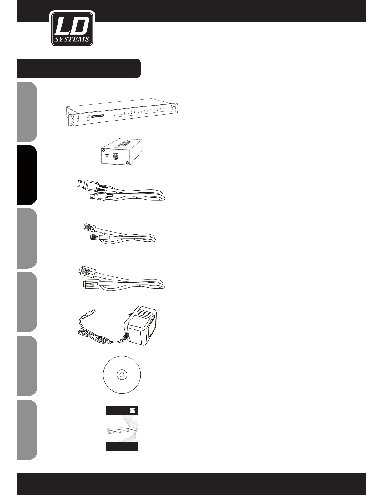
LIEFERUMFANG:
1 x WIN42 CONTROLLER HUB
1 x WIN42 USB zu RS485 Konverter
1 x USB-Kabel
16 x RJ11-Kabel
1 x RJ45-Kabel
1 x Netzadapter
1 x Software CD
1 x Bedienungsanleitung
POWER
WIN42 CONTROLLER HUB
COM
USER´S MANUAL
BEDIENUNGSANLEITUNG
MANUEL D`UTILISATION
MANUAL DE USUARIO
INSTRUKCJA OBSŁUGI
MANUALE D‘ USO
LD WIN42 CONTROLLER HUB
WIN42HUB
POWER
WIN42 CONTROLLER HUB
COM
Page 33
ITALIANOPOLSKIESPAÑOL
FRANCAISFRANCAIS FRANCAISFRANCAIS
FRANCAISDEUTSCHENGLISH
33
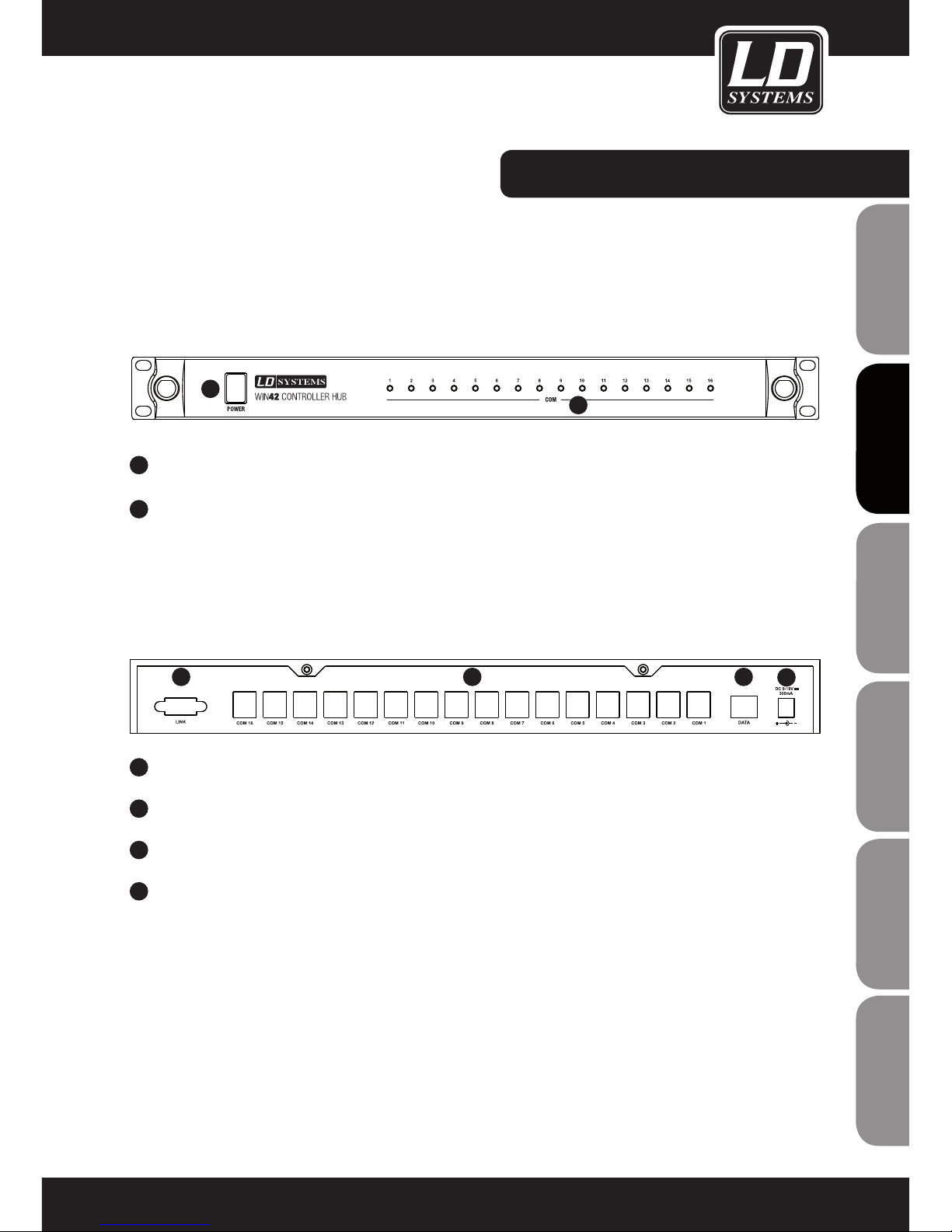
VORDER- / RÜCKSEITE:
1
EIN- / AUSSCHALTER
2
BETRIEBSANZEIGE LEDS 1-16 FÜR WIN42 EMPFÄNGER 1-16
1
KLEINSPANNUNGSBUCHSE FÜR NETZADAPTER (9 - 18 V DC, 300 MA)
2
DATA-ANSCHLUSS FÜR USB ZU RS485 KONVERTER
3
DATA-ANSCHLÜSSE (COM 1 - 16) FÜR WIN42 EMPFÄNGER
4
VORBEREITUNG FÜR PORT-ERWEITERUNG (Z. ZT. NICHT VERFÜGBAR)
VORDERSEITE
RÜCKSEITE
1
1
2
234
Page 34
ENGLISHDEUTSCHFRANCAIS
FRANCAISFRANCAIS FRANCAISFRANCAIS
ESpAñoLpoLSKIITALIANo
34
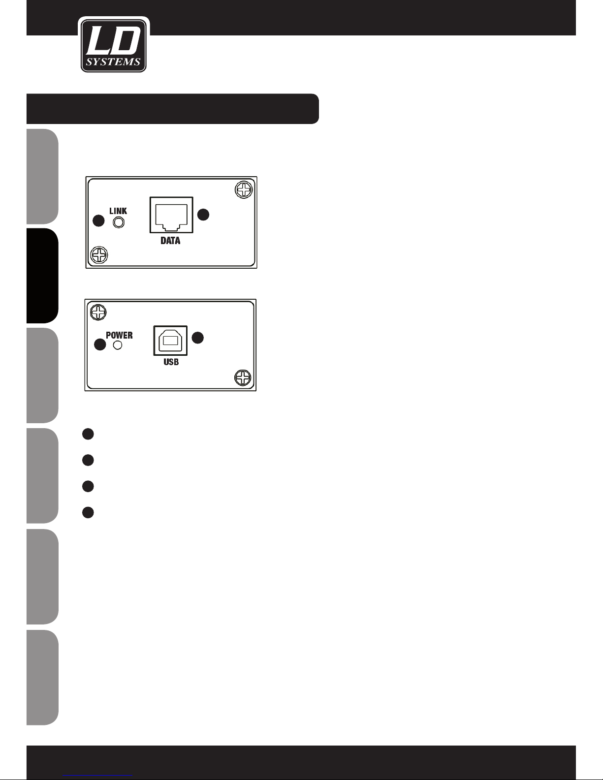
USB ZU RS485 KONVERTER:
1
RJ45-BUCHSE, ANSCHLUSS AN DEN WIN42HUB
2
USB-BUCHSE, ANSCHLUSS AN EINEN WINDOWS PC
3
POWER LED: LEUCHTET, WENN DER KONVERTER KORREKT ÜBER USB VERBUNDEN IST.
4
LINK LED: LEUCHTET, WENN DIE VERBINDUNG ZWISCHEN KONVERTER UND CONTROLLER HUB
KORREKT HERGESTELLT IST.
2
1
4
3
Page 35
ITALIANOPOLSKIESPAÑOL
FRANCAISFRANCAIS FRANCAISFRANCAIS
FRANCAISDEUTSCHENGLISH
35
SOFTWAREINSTALLATION:
SYSTEMANFORDERUNGEN
für die Software WIN42 CONTROL CENTER und den Treiber für den WIN42 CONTROLLER HUB: Windows
XP, Windows Vista, Windows 7 und Windows 8, einen freien USB 2.0 Anschluss und eine empfohlene
Monitorauflösung von mindestens 1366 x 768.
1. Legen Sie die mitgelieferte Software-CD in das optische Laufwerk Ihres Computers, öffnen diese und doppelklicken auf die
Datei „Setup“ und folgen den Anweisungen, um die Software WIN42 CONTROL CENTER auf Ihrem Computer zu installieren.
Page 36
ENGLISHDEUTSCHFRANCAIS
FRANCAISFRANCAIS FRANCAISFRANCAIS
ESpAñoLpoLSKIITALIANo
36
2. Sie werden nun mehrmals dazu aufgefordert „Next“ anzuklicken, um die Installation durchzuführen.
Klicken Sie auf „Close“ um die Installation abzuschließen.
SOFTWAREINSTALLATION:
Page 37
ITALIANOPOLSKIESPAÑOL
FRANCAISFRANCAIS FRANCAISFRANCAIS
FRANCAISDEUTSCHENGLISH
37
Schließen Sie den mitgelieferten USB zu RS485 Konverter an einen freien USB Anschluss Ihres Computers an.
TREIBERINSTALLATION:
Page 38
ENGLISHDEUTSCHFRANCAIS
FRANCAISFRANCAIS FRANCAISFRANCAIS
ESpAñoLpoLSKIITALIANo
38
TREIBERINSTALLATION:
Im Falle der auf der vorigen Seite abgebildeten Systemmeldungen installieren Sie den dazugehörigen Treiber, in dem Sie die
Windows-Taste Ihrer Tastatur drücken und auf „Systemsteuerung“ klicken.
Page 39
ITALIANOPOLSKIESPAÑOL
FRANCAISFRANCAIS FRANCAISFRANCAIS
FRANCAISDEUTSCHENGLISH
39
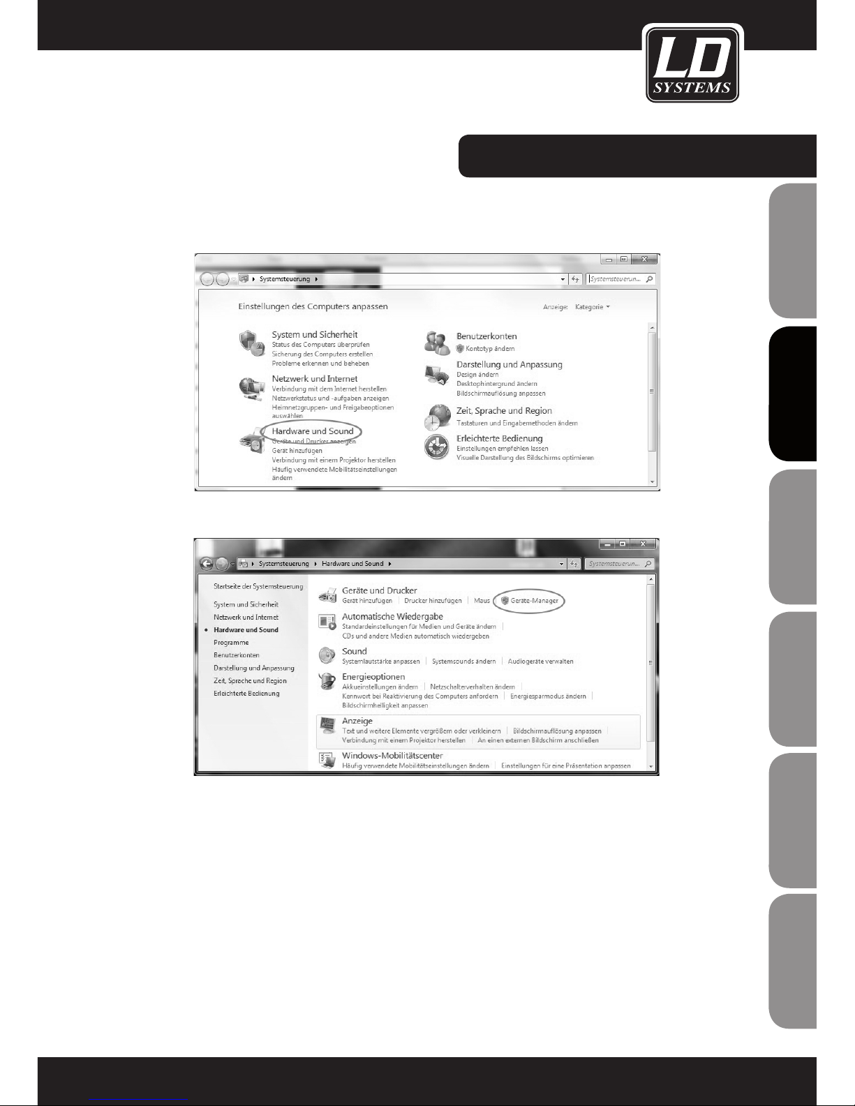
Das Fenster „Systemsteuerung“ öffnet sich. Klicken Sie nun auf „Hardware und Sound“ und dann auf „Geräte-Manager“.
TREIBERINSTALLATION:
Page 40
ENGLISHDEUTSCHFRANCAIS
FRANCAISFRANCAIS FRANCAISFRANCAIS
ESpAñoLpoLSKIITALIANo
40
TREIBERINSTALLATION:
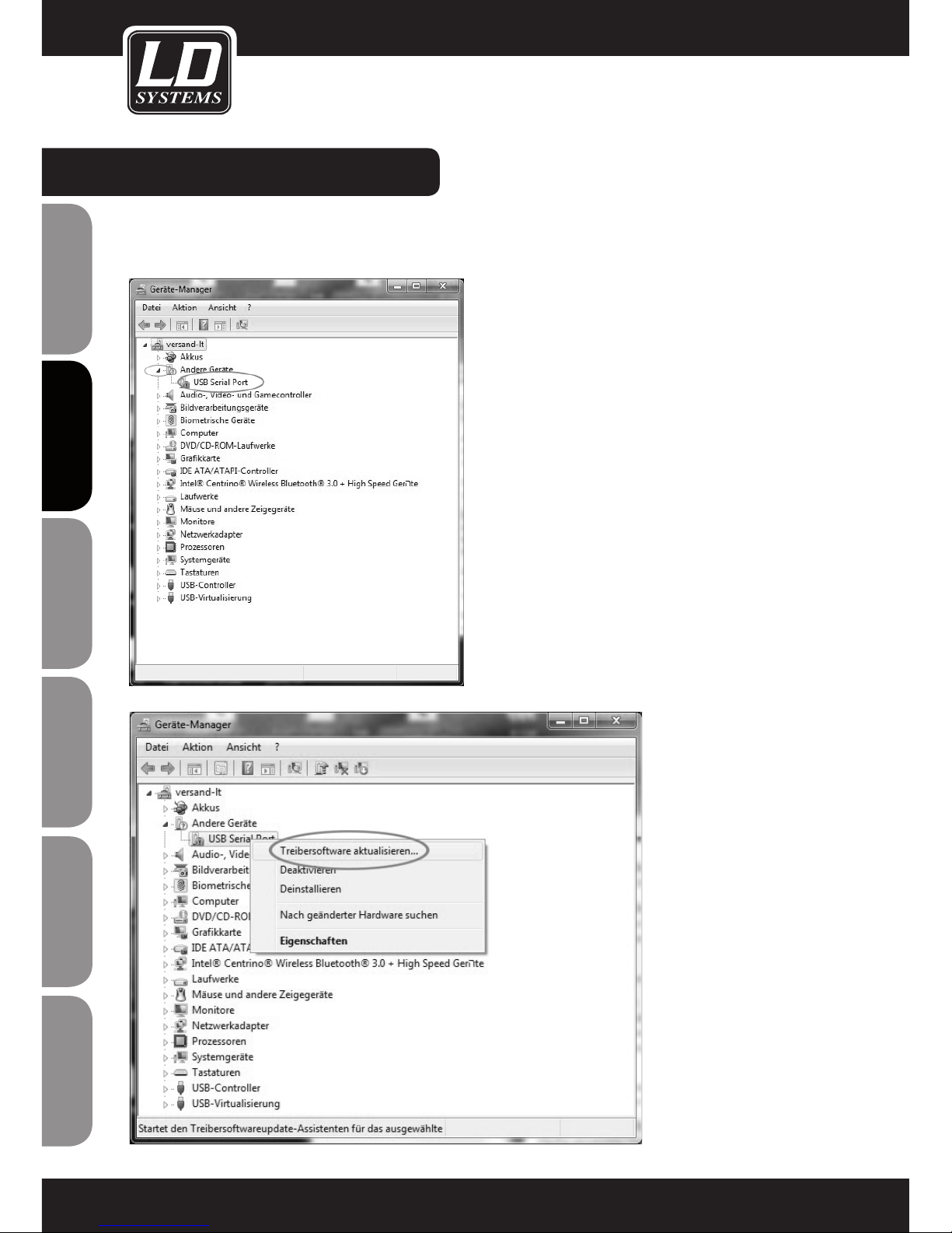
Wenn sich das Fenster für den Geräte-Manager geöffnet hat, klicken Sie auf den Pfeil neben „Andere Geräte“. Klicken Sie nun
mit der rechten Maustaste auf „USB Serial Port“ um danach auf „Treibersoftware aktualisieren“ zu klicken.
Page 41
ITALIANOPOLSKIESPAÑOL
FRANCAISFRANCAIS FRANCAISFRANCAIS
FRANCAISDEUTSCHENGLISH
41
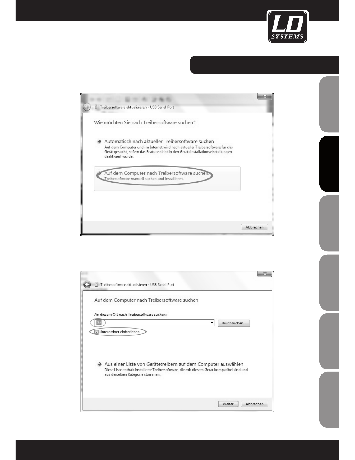
Klicken Sie nun mit der linken Maustaste auf „Auf dem Computer nach Treibersoftware suchen“.
Wählen Sie das optische Laufwerk Ihres Computers aus, in dem sich die mitgelieferte Software- und Treiber-CD befindet, klicken
„Unterordner einbeziehen“ an und setzen den Vorgang fort, indem Sie auf „Weiter“ klicken.
TREIBERINSTALLATION:
Page 42
ENGLISHDEUTSCHFRANCAIS
FRANCAISFRANCAIS FRANCAISFRANCAIS
ESpAñoLpoLSKIITALIANo
42
TREIBERINSTALLATION:
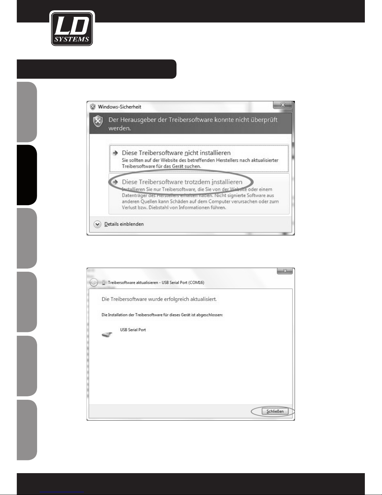
Falls folgende Meldung erscheint, klicken Sie auf „Diese Treibersoftware trotzdem installieren“.
Der Treiber ist nun installiert. Klicken Sie auf „Schließen“, um den Installationsvorgang zu verlassen.
Page 43
ITALIANOPOLSKIESPAÑOL
FRANCAISFRANCAIS FRANCAISFRANCAIS
FRANCAISDEUTSCHENGLISH
43
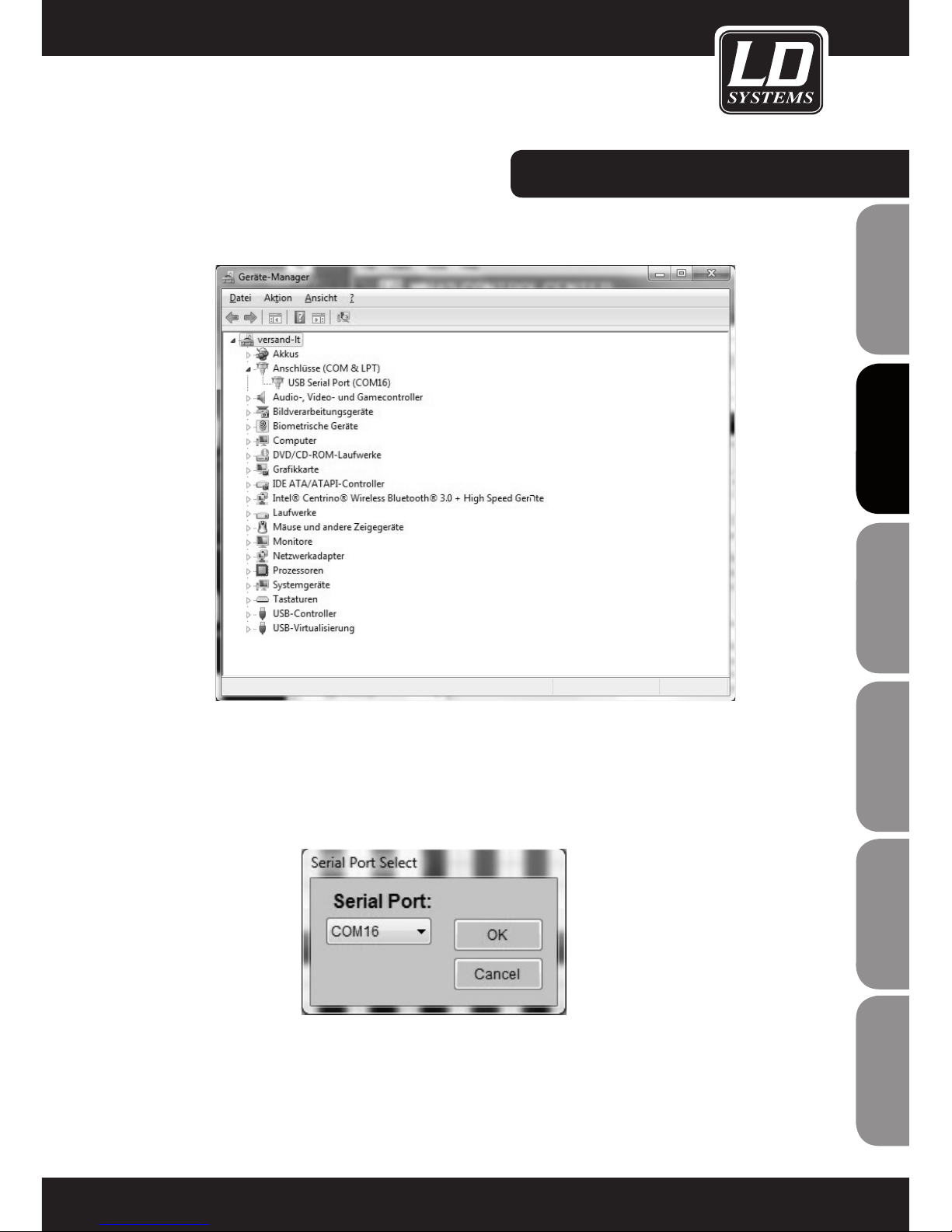
Sie sehen nun im Geräte-Manager die COM-Anschlussnummer des „USB Serial Port“.
Hinweis: Die COM-Anschlussnummer des „USB Serial Port“ muss zwischen 1 und 16 liegen.
Schließen Sie nun den WIN42 CONTROLLER HUB mit Hilfe des mitgelieferten RJ45-Kabels an den USB zu RS485 Konverter an
und öffnen die Software WIN42 CONTROL CENTER. Wählen Sie im Tools-Menü den Befehl „Communication“ aus, um zu sehen,
ob die Anschlussummer des „USB Serial Port“ und die Anschlussnummer im Programm WIN42 CONTROL CENTER übereinstimmen (in unserem Beispiel COM16).
TREIBERINSTALLATION:
Page 44
ENGLISHDEUTSCHFRANCAIS
FRANCAISFRANCAIS FRANCAISFRANCAIS
ESpAñoLpoLSKIITALIANo
44
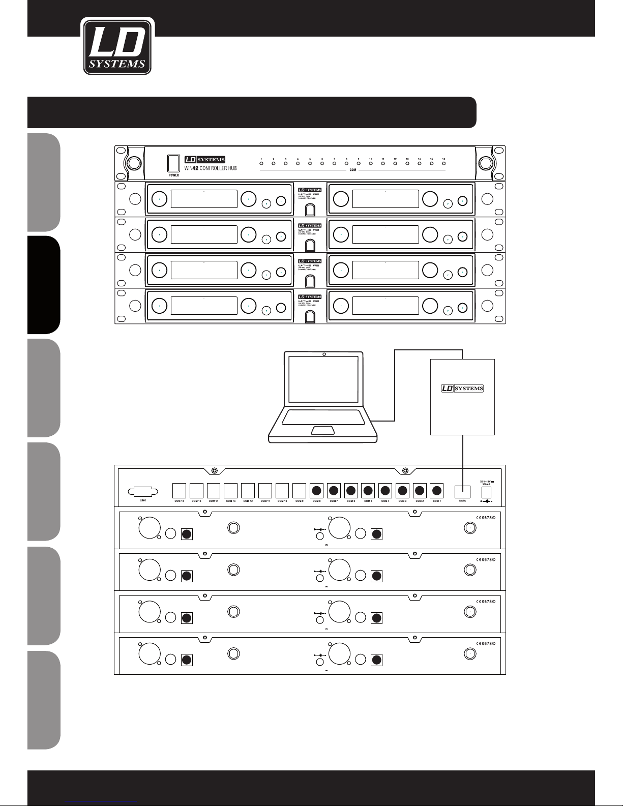
ANSCHLIESSEN DES WIN42 CONTROLLER HUB:
Hinweis: Das Kabel (16 Stück im Lieferumfang) zum Verbinden des WIN42 CONTROLLER HUB mit dem WIN42 Empfänger hat
zwei verschieden große Stecker. Der größere Stecker wird in die COM-Buchse (1 - 16) des WIN42 CONTROLLER HUB gesteckt,
der kleinere Stecker in die Data Output-Buchse des WIN42 Empfängers.
CHANNEL2
XLR BALANCED
UNBAL
OUTPUT
Data Output
ANTENNA-AANTENNA-B
CHANNEL1
XLR BALANCED
D.C 12-18V
1000mA
UNBAL
OUTPUT
Data Output
CHANNEL2
XLR BALANCED
UNBAL
OUTPUT
Data Output
ANTENNA-AANTENNA-B
CHANNEL1
XLR BALANCED
D.C 12-18V
1000mA
UNBAL
OUTPUT
Data Output
CHANNEL2
XLR BALANCED
UNBAL
OUTPUT
Data Output
ANTENNA-AANTENNA-B
CHANNEL1
XLR BALANCED
D.C 12-18V
1000mA
UNBAL
OUTPUT
Data Output
CHANNEL2
XLR BALANCED
UNBAL
OUTPUT
Data Output
ANTENNA-AANTENNA-B
CHANNEL1
XLR BALANCED
D.C 12-18V
1000mA
UNBAL
OUTPUT
Data Output
1
1
3
5
7
2
4
682345678
USB RS485
DATA CONVERTER
DATA
USB
Page 45
ITALIANOPOLSKIESPAÑOL
FRANCAISFRANCAIS FRANCAISFRANCAIS
FRANCAISDEUTSCHENGLISH
45
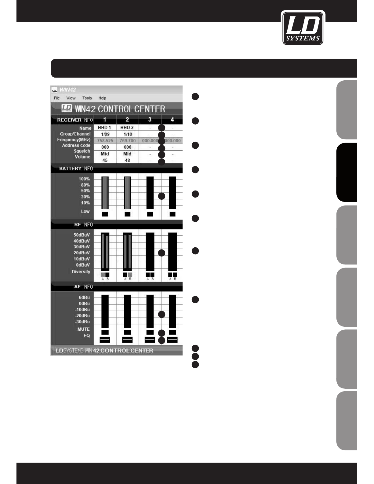
RECEIVER INFO
1
NAME
Klicken Sie hier, um den Namen des Empfängers
zu vergeben
2
GROUP/CHANNEL
Klicken Sie hier um die Frequenzgruppe und den
Kanal zu vergeben.
3
FREQUENCY
Anzeige der unter (2) eingestellten Group/Channel
Zuweisung
4
ADDRESS CODE
Klicken Sie hier, um die Adresse des Empfängers
zu vergeben (0-224)
5
SQUELCH
Klicken Sie hier, um die Squelch Einstellung des
Empfängers vorzunehmen (Low/Mid/High)
6
EINSTELLUNG DER EMPFÄNGER-LAUTSTÄRKE
(03-48)
BATTERY INFO
7
ANZEIGE DES BATTERIEZUSTANDS (0-100%)
Wenn sich der Batteriezustand des Senders einem
kritischen Zustand neigt, leuchtet die Anzeige
„LOW“ auf.
RF INFO
8
ANZEIGE DER EMPFANGSFELDSTÄRKE DES
EMPFÄNGERS
Der aktive Empfänger des Diversity Systems wird
mit den Anzeigen (A/B) signalisiert.
AF INFO
9
ANZEIGE DES SIGNALPEGELS AM EMPFÄNGER
10
ANZEIGE DES MUTE-STATUS AM EMPFÄNGER
11
EQ
Klicken Sie hier um die Equalizer-Einstellungen
des Empfängers zu ändern (Flat/Lowcut/
Lowcut+Highboost/Highboost)
BEDIENUNG DER WIN42 CONTROL CENTER SOFTWARE:
1
2
3
4
5
6
7
8
9
10
11
Page 46
ENGLISHDEUTSCHFRANCAIS
FRANCAISFRANCAIS FRANCAISFRANCAIS
ESpAñoLpoLSKIITALIANo
46
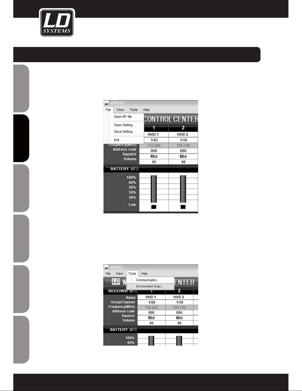
SETTINGS SPEICHERN UND AUFRUFEN
Alle Einstellungen, die Sie im Hauptfenster vornehmen, können Sie auf Ihrem Computer speichern und zu einem
späteren Zeitpunkt wieder aufrufen.
Wählen Sie dazu die Menüpunkte Open Setting oder Save Setting aus dem File Menü im Hauptfenster
ENVIRONMENT SCAN
Die Funktion Environment Scan bietet Ihnen die Möglichkeit, das gesamte Frequenzspektrum des LD Systems
WIN42 Systems zu scannen und auf einfache Art und Weise freie Frequenzen zu finden.
Bitte folgen sie dieser Anleitung Schritt für Schritt, um den vollen Funktionsumfang der Software auszunutzen.
Wählen Sie die Funktion Environment Scan im Tools Menü
BEDIENUNG DER WIN42 CONTROL CENTER SOFTWARE:
Page 47
ITALIANOPOLSKIESPAÑOL
FRANCAISFRANCAIS FRANCAISFRANCAIS
FRANCAISDEUTSCHENGLISH
47
Im Environment Scan Fenster stehen Ihnen folgende Funktionen zur Verfügung (Darstellung Environment Scan
beispielhaft)
1
6
7
8
9
3
5
2
4
SCAN MENÜ
1
PORT
Wählen Sie den Port eines der angeschlossenen Empfängers aus, der zum Scannen verwendet werden soll.
Hinweis: Dieser Empfänger kann während des Scannens für keine weitere Funktion genutzt werden.
2
START SCAN
Startet den Scan Vorgang. Der in der Port Auswahl definierte Empfänger wird zum Scannen der Umgebung
verwendet. Die Empfangsfeldstärke wird unmittelbar in der Grafik dargestellt. Der gesamte Vorgang kann
einige Minuten dauern.
Sollte der Scan-Vorgang nicht gestartet werden können, erscheint die Meldung „Scan Timeout“.
Vergewissern Sie sich in diesem Fall, dass der richtige Port (1) ausgewählt ist und der Empfänger korrekt
angeschlossen ist und funktioniert.
3
STOP
Stoppt den Scan-Vorgang
4
SAVE PIC
Klicken Sie hier, um das Scan Ergebnis als Bilddatei (*.jpg) auf Ihrem Computer zu speichern
5
SCAN TABLE
Klicken Sie hier, um das Scan Ergebnis als Tabelle anzuzeigen und die Zuweisung von freien Frequenzen zu
den angeschlossenen Empfängern vorzunehmen. Siehe auch Abschnitt „Scan Table“.
6
SHOW GRID
Blendet das Koordinaten-Gitter in der Darstellung ein und aus.
Page 48
ENGLISHDEUTSCHFRANCAIS
FRANCAISFRANCAIS FRANCAISFRANCAIS
ESpAñoLpoLSKIITALIANo
48
7
ZOOM IN
Klicken Sie hier, um einen Ausschnitt zu vergrößern. Markieren Sie mit der Maus den Bereich der vergrößert
dargestellt werden soll.
8
AUTO COORDINATE
Klicken Sie hier, um die automatische Anpassung der Koordinaten ein- oder auszuschalten.
9
DEFAULT COORDINATE
Klicken Sie hier, um aus der Zoom-Darstellung zurückzukehren und um die gesamte Grafik anzuzeigen.
SCAN TABLE
(Darstellung Scan Table beispielhaft)
In dieser Darstellung haben Sie die Möglichkeit, freie Frequenzen zu finden und den angeschlossenen
Empfängern zuzuweisen.
Führen Sie den Environment Scan wie beschrieben durch und klicken Sie auf Scan Table um das Scan-Ergebnis
in Tabellenform darzustellen. Hier finden Sie alle verfügbaren Frequenzgruppen mit den dazugehörigen
Frequenzen. Die Ergebnisse des Environment Scans sind für jede Frequenz als Wert der gemessenen Feldstärke
dargestellt. Welche Frequenzen in der gewünschten Gruppe verfügbar sind, wird zudem farblich markiert.
Weiß: Empfangsfeldstärke 0dBuV oder niedriger freie Frequenz
Gelb: Empfangsfeldstärke 0dBuV bis 20dBuV Frequenz möglicherweise belegt
Rot: Empfangsfeldstärke 20dBuV oder höher Frequenz belegt
Speichern Sie die Scan-Tabelle durch einen Klick auf den Save-Button am unteren rechten Bildschirmrand ab,
um zu einem späteren Zeitpunkt auf die Ergebnisse zurückgreifen zu können.
Um eine gespeicherte Scan-Tabelle aufzurufen, wählen Sie den Menüpunkt Open RF File aus dem File-Menu im
Hauptfenster.
BEDIENUNG DER WIN42 CONTROL CENTER SOFTWARE:
Page 49
ITALIANOPOLSKIESPAÑOL
FRANCAISFRANCAIS FRANCAISFRANCAIS
FRANCAISDEUTSCHENGLISH
49
ZUWEISEN VON FREQUENZEN
Doppelklicken Sie auf eine Frequenz, die Sie einem der angeschlossenen Empfänger zuweisen möchten.
Daraufhin gelangen Sie automatisch in den Hauptbildschirm zurück.
Durch Blinken der Empfänger-Nummer wird Ihnen signalisiert, welchem Empfänger die gewählte Frequenz
zugewiesen werden kann. Wählen Sie einen Empfänger aus, in dem Sie auf die entsprechende EmpfängerNummer klicken. Die gewählte Frequenz aus der Scan Table wird dem gewünschten Empfänger zugewiesen.
Wiederholen Sie den Vorgang so lange, bis allen verfügbaren Empfängern Frequenzen zugewiesen wurden. Um
die nun programmierten Empfänger mit ihren Sendern zu synchronisieren, verwenden Sie die Sync-Funktion des
Empfängers oder stellen Sie die Frequenz manuell am Sender ein.
BEDIENUNG DER WIN42 CONTROL CENTER SOFTWARE:
Page 50
ENGLISHDEUTSCHFRANCAIS
FRANCAISFRANCAIS FRANCAISFRANCAIS
ESpAñoLpoLSKIITALIANo
50
Produktart Kontrolleinheit für WIN42 Funksysteme
Typ softwaregestützt
Anzahl unterstützter Funksysteme 16
Anzeigeelemente 16 x Betriebsanzeige LED
Betriebsspannung 9 V - 18 V DC, 300 mA
Breite 482 mm
Höhe 44 mm
Tiefe 160 mm
Gewicht 1.850 g
Mitgeliefertes Zubehör USB zu RS485 Konverter, 1 x USB-Kabel, 16 x RJ11-Kabel, 1 x RJ45-Kabel, 1 x
Netzadapter, Software CD
TECHNISCHE DATEN:
Page 51
ITALIANOPOLSKIESPAÑOL
FRANCAISFRANCAIS FRANCAISFRANCAIS
FRANCAISDEUTSCHENGLISH
51
GARANTIEBESTIMMUNGEN
Diese Garantie erstreckt sich auf die Marken Adam Hall, LD Systems, LD Premium, Defender, Palmer, Cameo und
Eminence.
Die gesetzlichen Gewährleistungsrechte gegenüber dem Verkäufer werden von dieser Garantie nicht berührt. Vielmehr begründet diese Garantie zusätzliche selbständige Ansprüche gegenüber Adam Hall.
Mit dieser Garantie stellt Adam Hall sicher, dass das von Ihnen bei Adam Hall oder einem Adam Hall Partner
erworbene Produkt bei normalem Gebrauch während des Zeitraums von 2 bzw. 3 Jahren ab Kaufdatum frei von
Material- oder Verarbeitungsfehlern ist.
Der Garantiezeitraum beginnt mit dem Datum des Kaufs.
Der Geltendmachung eines Anspruchs auf Garantieleistungen erforderliche Nachweis des Kaufdatums, erfolgt
durch die mit dem Kaufdatum versehene Quittung oder den mit dem Kaufdatum versehenen Lieferschein. Sie haben Anspruch auf den Garantieservice zu den in diesem Dokument aufgeführten Bedingungen und Bestimmungen,
falls eine Reparatur der unter den oben genanten Marken vertriebenen Produkte innerhalb des Garantiezeitraums
erforderlich ist.
Diese Garantie gilt nur für den ursprünglichen Käufer des von Adam Hall vertriebenen Produkts und ist nicht an
Personen übertragbar, denen vom ursprünglichen Käufer das Eigentum am Adam Hall Produkt übertragen wird.
Innerhalb des Garantiezeitraums werden die fehlerhaften Komponenten oder das Produkt von Adam Hall repariert
oder ersetzt. Alle im Rahmen dieser Garantie entfernten Komponenten und Hardware-Produkte gehen in das Eigentum von Adam Hall über.
In dem unwahrscheinlichen Fall, dass bei dem von Ihnen erworbenen Adam Hall Produkt ein Fehler wiederholt auftritt, kann Adam Hall nach eigenem Ermessen entscheiden, Ihnen dieses Produkt durch ein vergleichbares Produkt
mit mindestens derselben Leistung zu ersetzen.
Adam Hall übernimmt keine Garantie für einen störungs- oder fehlerfreien Betrieb dieses Produkts. Adam Hall
übernimmt keine Verantwortung für auf eine inkorrekte Befolgung der im Lieferumfang des Adam Hall erhaltenen
Anweisungen zurückzuführende Schäden.
Diese Garantie erstreckt sich nicht auf:
- Verschleißteile (z.B. Akkumulator).
- Geräte deren Seriennummer entfernt wurde oder die beschädigt oder fehlerhaft wurden als folge eines Unfalls
- nicht sachgerechter oder missbräuchlicher Verwendung oder anderer missbräuchlicher Verwendung oder anderer äußerer Ursachen,
- Geräte die nicht entsprechend den Betriebsparametern betrieben wurden, die in den im Lieferumfang des Produkts enthaltenen Benutzerunterlagen festgelegt sind
- Geräte die aufgrund der Verwendung nicht von Adam Hall hergestellter oder vertriebener Teile repariert wurde
- Geräte die durch Änderung oder Wartung durch jemand anderen als Adam Hall getätigt wurde.
Diese Bestimmungen und Bedingungen stellen die vollständige und ausschließliche Garantievereinbarung zwischen Ihnen und Adam Hall für das von Ihnen erworbene Adam Hall Produkt dar.
HERSTELLERERKLÄRUNGEN:
Page 52
ENGLISHDEUTSCHFRANCAIS
FRANCAISFRANCAIS FRANCAISFRANCAIS
ESpAñoLpoLSKIITALIANo
52
HAFTUNGSBESCHRÄNKUNG
Wenn das unter der Marke Adam Hall vertriebene Produkt nicht entsprechend der obigen Garantie funktioniert,
besteht Ihr alleiniger und ausschließlicher Anspruch aus dieser Garantie in der Reparatur oder dem Ersatz.
Weitergehende Gewährleistungsansprüche bleiben hiervon unberührt. Die maximale Haftung von Adam Hall im
Rahmen dieser Garantie ist ausdrückliche beschränkt auf den jeweils niedrigeren Betrag, der sich entweder aus
dem Kaufpreis für das Produkt oder aus den Reparatur- bzw. Ersatzkosten von Hardware-Komponenten, die bei
normalem Gebrauch nicht Ordnungsgemäß funktionieren, ergibt.
Adam Hall haftet aus dieser Garantie nicht für durch das Produkt oder sein versagen verursachte Schäden, ein
schließlich entgangener Gewinne, unterbliebener Einsparungen oder besonderer, indirekter oder Folgeschäden.
Adam Hall haftet zudem nicht für von Dritten oder von ihnen für Dritte geltend gemachte Ansprüche.
Diese Haftungsbeschränkung gilt unabhängig davon, ob Schäden gerichtlich verfolgt werden, ob Schadenser
satzansprüche im Rahmen dieser Garantie oder aufgrund unerlaubter Handlungen (Einschließlich Fahrlässigkeit
und Gefährdungshaftung) oder aufgrund vertraglicher bzw. sonstiger Ansprüche gestellt werden. Diese Haftungs
beschränkung kann von keiner Person aufgehoben oder ergänzt werden. Diese Haftungsbeschränkung gilt auch
dann, wenn sie Adam Hall über die Möglichkeit derartiger Schäden informiert haben. Sie gilt jedoch nicht für
Ansprüche aus Personenschäden.
Aus dieser Garantie ergeben sich für Sie bestimmte Rechte. Möglicherweise haben Sie weitere Rechte, die Ihnen
von Staat zu Staat und von Land zu Land unterschiedlich sein können. Es ist ratsam, die entsprechenden Gesetze
des Staates bzw. Landes heranzuziehen, um Ihre Rechte umfassend zu ermitteln.
INANSPRUCHNAHME DES REPARATURSERVICE
Um den Garantieservice bzw. Reparaturservice für das Produkt in Anspruch zu nehmen, wenden Sie sich bitte an
Adam Hall oder an einen Adam Hall Partner, bei dem Sie das Produkt erworben haben.
EG-KONFORMITÄTSERKLÄRUNG
Diese Geräte entsprechen den grundlegenden Anforderungen und den weiteren Vorgaben der Richtlinien
2004/108/EC (EMC) und 2006/95/EC (LVD). Weitere Informationen finden Sie unter www.adamhall.com.
KORREKTE ENTSORGUNG DIESES PRODUKTES
(Gültig in der Europäischen Union)
Dieses Symbol (entweder auf dem Gerät oder dem dazugehörigen Handbuch) weist darauf hin, dass das Gerät
nicht mit dem normalen Hausmüll entsorgt werden darf. Um mögliche Schäden an der Umwelt und an Personen
zu verhindern, entsorgen Sie dieses Gerät bitte fachgerecht bei einer entsprechenden Stelle für Elektromüll.
Als Privatkunde Informieren Sie sich bitte beim Hersteller oder bei Ihrer Gemeinde über die
Möglichkeiten der korrekten Entsorgung.
Als Geschäftskunde kontaktieren Sie bitte Ihren Lieferanten und prüfen Sie die Konditionen
zur Entsorgung der Geräte. Dieses Produkt sollte nicht mit anderem gewerblichen Abfall entsorgt werden.
HERSTELLERERKLÄRUNGEN:
Page 53
ITALIANOPOLSKIESPAÑOL
FRANCAISFRANCAIS FRANCAISFRANCAIS
FRANCAISDEUTSCHENGLISH
53
WEEE-DEKLARATION
Ihr LD-Systems Produkt wurde unter der Verwendung hochwertiger Materialien und Komponenten die wiederverwertet oder wieder verwendet werden können hergestellt. Dieses Symbol weist darauf hin, dass elektronische
Geräte nicht im normalen Hausmüll entsorgt werden dürfen. Entsorgen Sie dieses Gerät bitte fachgerecht bei
einer entsprechenden Stelle für Elektromüll und helfen Sie dabei unsere Umwelt zu schützen.
BATTERIEN UND AKKUS
Die mitgelieferten Batterien können wiederverwertet werden. Werfen Sie die Batterien daher nicht in den normalen Hausmüll sondern in gesonderte dafür vorgesehene Container. Helfen Sie, unsere Umwelt sauber zu halten.
UMWELTSCHUTZ UND ENERGIESPAREN
Energiesparen ist ein aktiver Beitrag zum Umweltschutz. Schalten Sie bitte alle nicht benötigten elektrischen
Geräte aus. Um zu verhindern, dass nicht benötigte Geräte im Standby-Modus Strom verbrauchen, ziehen Sie
den Netzstecker.
Adam Hall GmbH, alle Rechte vorbehalten. Änderungen der Technischen Daten und Produktmerkmale vorbehalten. Das Erstellen von Fotokopien, Übersetzungen und anderen Reproduktionen dieser Bedienungsanleitung
oder Teilen derselben ohne vorherige Genehmigung ist untersagt.
HERSTELLERERKLÄRUNGEN:
Page 54
ENGLISHDEUTSCHFRANCAIS
FRANCAISFRANCAIS FRANCAISFRANCAIS
ESpAñoLpoLSKIITALIANo
54
Merci d’avoir choisi LD-Systems!
Nous avons conçu ce produit afin de vous offrir un matériel fiable, qui vous accompagnera durant de longues
années. En achetant l’un des produits de la marque LD-Systems vous bénéficiez de notre compétence reconnue
et de nos nombreuses années d’expérience en tant que fabricant. Notre nom est notre garantie.
Veuillez s’il-vous-plait prendre quelques minutes pour lire attentivement ces instructions d’utilisation car nous
souhaitons que vous puissiez profiter pleinement et au plus vite de votre matériel LD-Systems.
Pour plus d’informations sur LD-Systems venez visiter notre site WWW.LD-SYSTEMS.COM
Introduction
Le LD Systems WIN42HUB et le logiciel complémentaire WIN42 CONTROL CENTER assurent le suivi et le
pilotage d'un maximum de 16 récepteurs WIN42. Son interface graphique permet de visualiser et de contrôler,
pour chacun des émetteurs WIN42 connectés, la fréquence HF utilisée, le statut des batteries/piles, le niveau
du signal HF, celui du signal audio et bien d'autres paramètres. Le logiciel offre par ailleurs une fonction
"Environment Scan", permettant de trouver facilement, où qu'on se trouve, des fréquences de réception libres.
Page 55
ITALIANopoLSKIESpAñoL
FRANCAISFRANCAIS FRANCAISFRANCAIS
FRANCAISDEUTSCHENGLISH
55
POWER
WIN42 CONTROLLER HUB
COM
LD WIN42HUB
WIN42HUB
Page 56
ENGLISHDEUTSCHFRANCAIS
FRANCAISFRANCAIS FRANCAISFRANCAIS
ESpAñoLpoLSKIITALIANo
56
1. Veuillez lire attentivement ces instructions.
2. Gardez ces instructions et informations en lieu sûr.
3. Veuillez suivre ces instructions.
4. Veuillez respecter tous les avertissements. N'enlevez pas les instructions de sécurité ou toute autre information collée sur l'appareil.
5. N'utilisez l'appareil que conformément à l'usage auquel il est destiné.
6. Use only stable and appropriate stands and/or mounts when the device is permanently installed. Vérifiez bien
que les supports muraux sont solidement fixés. Vérifiez que l'appareil est installé de façon stable, et ne peut
tomber.
7. When installing please observe the corresponding safety standards for your country.
8. Do not install the device near radiators, heat accumulators, ovens or other sources of heat. Veillez à assurer un
refroidissement suffisant de l'appareil, afin d'éviter
9. 9. Ne posez aucune source de flamme nue sur l'appareil (bougie allumée, par exemple).
10. 10. N'obstruez pas les ouïes de ventilation.
11. Do not operate the device in the immediate vicinity of water. Do not expose this equipment to combustible
materials, liquids or gases.
12. Vérifiez qu'aucune éclaboussure ou infiltration d'eau n'est possible dans l'appareil. Do not put objects filled
with fluids, such as vases or drinking vessels, on top of the device.
13. Vérifiez qu'aucun objet ne peut tomber dans l'appareil.
14. N'utilisez l'appareil qu'avec des accessoires dont l'emploi a été prévu par le fabricant.
15. ATTENTION : If this device has a mains connector equipped with protective earth, it must be connected to a
mains socket with a protective ground connection. Ne désactivez jamais la fonction de protection par mise à la
terre du cordon secteur livré.
16. Do not turn on the device immediately if it was exposed to strong temperature fluctuations (for example after
transportation). Moisture and condensation may damage the device. Leave the device switched off until it has
reached room temperature.
17. Do not open the device and do not make any changes to the device.
18. Before connecting to mains power, make certain that the mains voltage and the mains frequency are the
same as the operating values of the device (see type label). If the device is equipped with a supply voltage selector switch, make certain that the values of the device match the values of the mains power before connecting.
If the plug on the included cord does not fit your mains outlet, contact your electrician.
19. Veillez à éviter tout piétinement du cordon secteur. Protégez le cordon secteur de toute flexion excessive, que
ce soit côté prise murale ou côté appareil.
20. Pour éviter tout dommage ou incident, par exemple si quelqu'un a trébuché sur le câble, vérifiez tous les
branchements une fois que vous avez branché l'appareil.
21. Lorsque vous branchez l'appareil, vérifiez que la prise murale reste facilement accessible.
Always pull out the power plug when the device is not in use or when you clean the device. Disconnect the
power cord by pulling the plug not the cable. Ne touchez pas le câble secteur ni l‘adaptateur à mains nues.
22. Avoid switching the device on and off at short intervals, because it may shorten the durability of the device.
23. IMPORTANT: Replace fuse only by fuse of same type and rating! If fuse blows repeatedly please contact
authorized service center!
24. Si vous désirez désolidariser complètement l'appareil de la tension secteur, il faut débrancher la prise
murale.
MESURES PRÉVENTIVES :
Page 57
ITALIANopoLSKIESpAñoL
FRANCAISFRANCAIS FRANCAISFRANCAIS
FRANCAISDEUTSCHENGLISH
57
25. If your device is equipped with a Volex power connector, the matching Volex device plug must be unlocked
in order to disconnect it. Du même coup, toute sollicitation sur le cordon secteur est susceptible de déplacer
l'appareil, ce qui peut provoquer des blessures et/ou des dégâts matériels. Il vaut donc mieux, par conséquent,
soigner les passages de câbles.
26. If there is a risk of lightning strike or during extended periods of disuse, unplug the power plug.
27. During transport, make certain that the equipment being transported cannot fall down and possibly cause
personal injuries and/or property damage.
28. Si votre appareil ne fonctionne plus correctement, s'il a été exposé à du liquide ou si un objet est tombé à
l'intérieur, ou en cas de dommage, quel qu'il soit, éteignez-le immédiatement et débranchez sa prise murale. Cet
appareil ne doit être réparé que par des experts autorisés.
29. Pour nettoyer l'appareil, utilisez exclusivement un chiffon sec
30. Respectez toutes les lois en vigueur dans votre pays pour jeter l'emballage. Veuillez séparer le plastique et le
papier/carton.
31. Mettez les films plastique hors de portée des enfants.
CAUTION
RISK OF ELECTRIC SHOCK
DO NOT OPEN
MESURES PRÉVENTIVES :
ATTENTION :
Pour éviter tout risque d'électrocution, ne démontez pas le capot (ou le panneau arrière). L'appareil ne contient
aucune pièce réparable par l'utilisateur. Veuillez confier la maintenance de l'appareil à un personnel qualifié.
Le pictogramme d'éclair, ou flèche dans un triangle équilatéral, est prévu pour alerter
l'utilisateur de la présence d'une "tension dangereuse" non protégée à l'intérieur du coffret de
l'appareil, d'une valeur suffisamment élevée pour constituer un risque pour l'organisme humain.
Le point d'exclamation à l'intérieur d'un triangle équilatéral sert à attirer l'attention de l'utilisateur sur
la présence d'instructions importantes, relatives à l'utilisation ou à la maintenance, dans la brochure
livrée avec l'appareil.
ATTENTION ! NIVEAUX SONORES ÉLEVÉS !
Cet appareil sera utilisé dans le cadre d'applications professionnelles. Par conséquent, son utilisation commerciale est soumise aux lois et aux réglementations en vigueur dans votre secteur d'activités. En tant que fabricant,
Adam Hall est tenu de vous informer formellement de l'existence de certains risques sanitaires.
Dommages auditifs, exposition prolongée à des niveaux sonores excessifs : ce caisson de basses est capable de
générer des niveaux de pression sonore (SPL) suffisants pour causer des dommages auditifs irréversibles aux
artistes, aux équipes de production et au public. Attention à éviter toute exposition prolongée à des niveaux de
pression sonore supérieurs à 90 dB SPL.
ENGLISH
Page 58
ENGLISHDEUTSCHFRANCAIS
FRANCAISFRANCAIS FRANCAISFRANCAIS
ESpAñoLpoLSKIITALIANo
58
CONTENUDU CARTON :
1 x HUB CONTRÔLEUR WIN42
1 x convertisseur WIN42 USB vers RS485
1 x câble USB
16 x câbles RJ11
1 x câble RJ45
1 x bloc secteur
1 x CD-ROM avec le logiciel
1 x Manuel Utilisateur
POWER
WIN42 CONTROLLER HUB
COM
USER´S MANUAL
BEDIENUNGSANLEITUNG
MANUEL D`UTILISATION
MANUAL DE USUARIO
INSTRUKCJA OBSŁUGI
MANUALE D‘ USO
LD WIN42 CONTROLLER HUB
WIN42HUB
POWER
WIN42 CONTROLLER HUB
COM
Page 59
ITALIANopoLSKIESpAñoL
FRANCAISFRANCAIS FRANCAISFRANCAIS
FRANCAISDEUTSCHENGLISH
59
FACE AVANT- / PANNEAU ARRIÈRE :
1
INTERRUPTEUR MARCHE / ARRÊT
2
INDICATEURS LED 1 À 16 POUR RÉCEPTEURS WIN42 1 À 16
1
EMBASE POUR BLOC SECTEUR (TENSION CONTINUE 9 À 18 VOLTS, 300 MA)
2
PORT DATA POUR CONVERTISSEUR USB VERS RS485
3
PORTS DATA (COM 1 À 16) POUR RÉCEPTEURS WIN42
4
DÉCOUPE POUR EXTENSION PORTS (EN COURS DE DÉVELOPPEMENT)
FACE AVANT
PANNEAU ARRIÈRE
1
1
2
234
Page 60
ENGLISHDEUTSCHFRANCAIS
FRANCAISFRANCAIS FRANCAISFRANCAIS
ESpAñoLpoLSKIITALIANo
60
CONVERTISSEUR USB VERS RS485 :
1
PORT RJ45, LIAISON VERS LE WIN42HUB
2
PORT USB, LIAISON VERS UN PC SOUS WINDOWS
3
LED POWER : S'ALLUME LORSQUE LA LIAISON USB DU CONVERTISSEUR EST CORRECTEMENT
ÉTABLIE.
4
LED LINK : S'ALLUME LORSQUE LA LIAISON ENTRE LE CONVERTISSEUR ET LE HUB CONTRÔLEURS
EST CORRECTEMENT ÉTABLIE.
2
1
4
3
Page 61
ITALIANopoLSKIESpAñoL
FRANCAISFRANCAIS FRANCAISFRANCAIS
FRANCAISDEUTSCHENGLISH
61
INSTALLATION DU LOGICIEL :
CONFIGURATION SYSTÈME
pour le logiciel WIN42 CONTROL CENTER et les pilotes pour le HUB CONTRÔLEUR WIN42 : Windows XP, Windows
Vista, Windows 7 ou Windows 8, un port USB 2.0 libre, résolution moniteur conseillée 1366 x 768 au moins.
1. Introduisez le CD-ROM livré dans le lecteur optique de votre ordinateur ; ouvrez-le depuis le Bureau, puis double-cliquez sur
l'icône "Setup" et suivez les instructions pour installer le logiciel WIN42 CONTROL CENTER sur votre ordinateur.
Page 62
ENGLISHDEUTSCHFRANCAIS
FRANCAISFRANCAIS FRANCAISFRANCAIS
ESpAñoLpoLSKIITALIANo
62
INSTALLATION LOGICIEL :
2. Plusieurs écrans se succèdent alors ; cliquez sur "Next" pour poursuivre l'installation.
Cliquez sur "Close" pour sortir de l'installation.
Page 63
ITALIANopoLSKIESpAñoL
FRANCAISFRANCAIS FRANCAISFRANCAIS
FRANCAISDEUTSCHENGLISH
63
Connectez le convertisseur USB vers RS485 livré à un port USB libre de votre ordinateur.
INSTALLATION PILOTES :
Page 64
ENGLISHDEUTSCHFRANCAIS
FRANCAISFRANCAIS FRANCAISFRANCAIS
ESpAñoLpoLSKIITALIANo
64
INSTALLATION PILOTES :
Si le message de la page précédente apparaît, il faut installer les pilotes correspondants. Appuyez sur la touche Windows de
votre clavier d'ordinateur, puis cliquez sur Panneau de Configuration.
Page 65
ITALIANopoLSKIESpAñoL
FRANCAISFRANCAIS FRANCAISFRANCAIS
FRANCAISDEUTSCHENGLISH
65
La fenêtre Panneau de Configuration apparaît alors. Cliquez sur "Matériel et Audio", puis sur "Gestionnaire de Périphériques".
INSTALLATION PILOTES :
Page 66
ENGLISHDEUTSCHFRANCAIS
FRANCAISFRANCAIS FRANCAISFRANCAIS
ESpAñoLpoLSKIITALIANo
66
INSTALLATION PILOTES :
Dans la fenêtre Gestionnaire de Périphériques, cliquez sur la flèche située à côté de "Autres Périphériques" Cliquez avec le
bouton droit de la souris sur "Port série USB", puis sur "Mettre à jour les pilotes logiciels".
Page 67
ITALIANopoLSKIESpAñoL
FRANCAISFRANCAIS FRANCAISFRANCAIS
FRANCAISDEUTSCHENGLISH
67
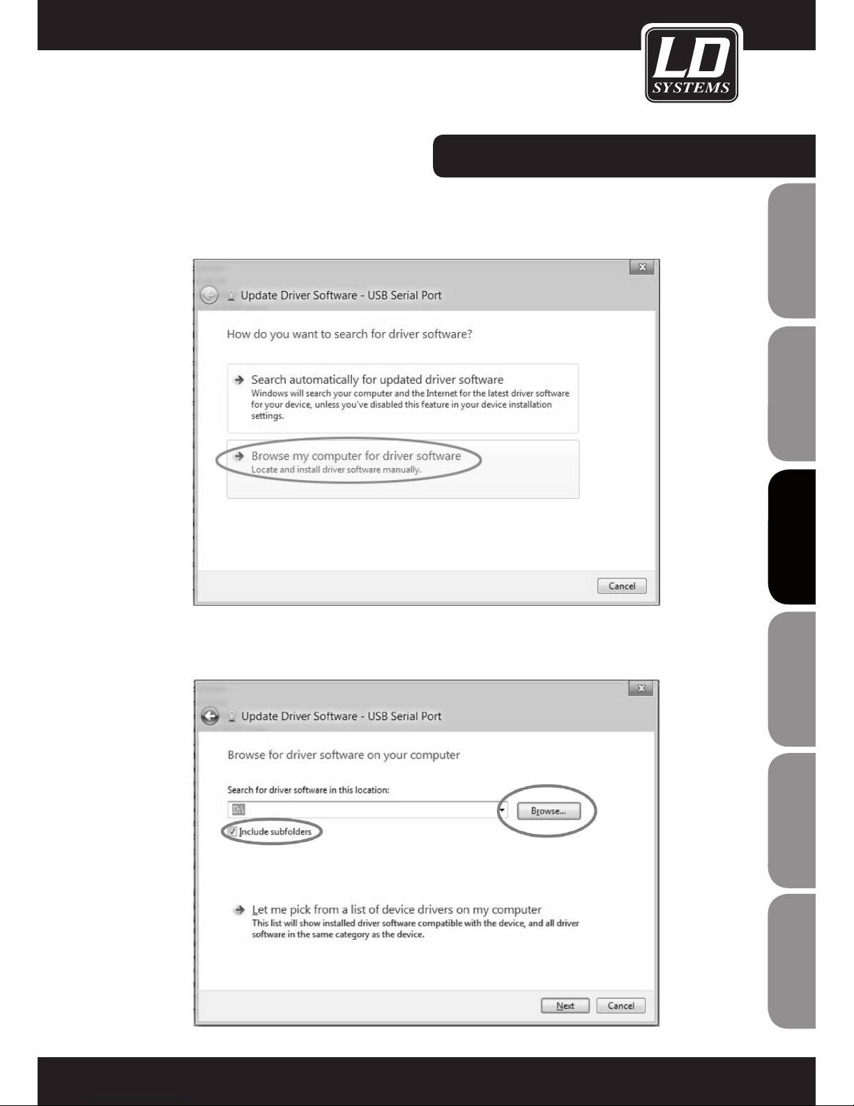
Cliquez alors, avec le bouton gauche de la souris, sur "Rechercher des Pilotes sur l‘Ordinateur".
Choisissez le lecteur optique de l'ordinateur, dans lequel se trouve le CD-ROM de logiciels/pilotes livré avec l'appareil ; cliquez
sur "Include subfolders" puis poursuivez en cliquant sur "Next".
INSTALLATION PILOTES :
Page 68
ENGLISHDEUTSCHFRANCAIS
FRANCAISFRANCAIS FRANCAISFRANCAIS
ESpAñoLpoLSKIITALIANo
68
INSTALLATION PILOTES :
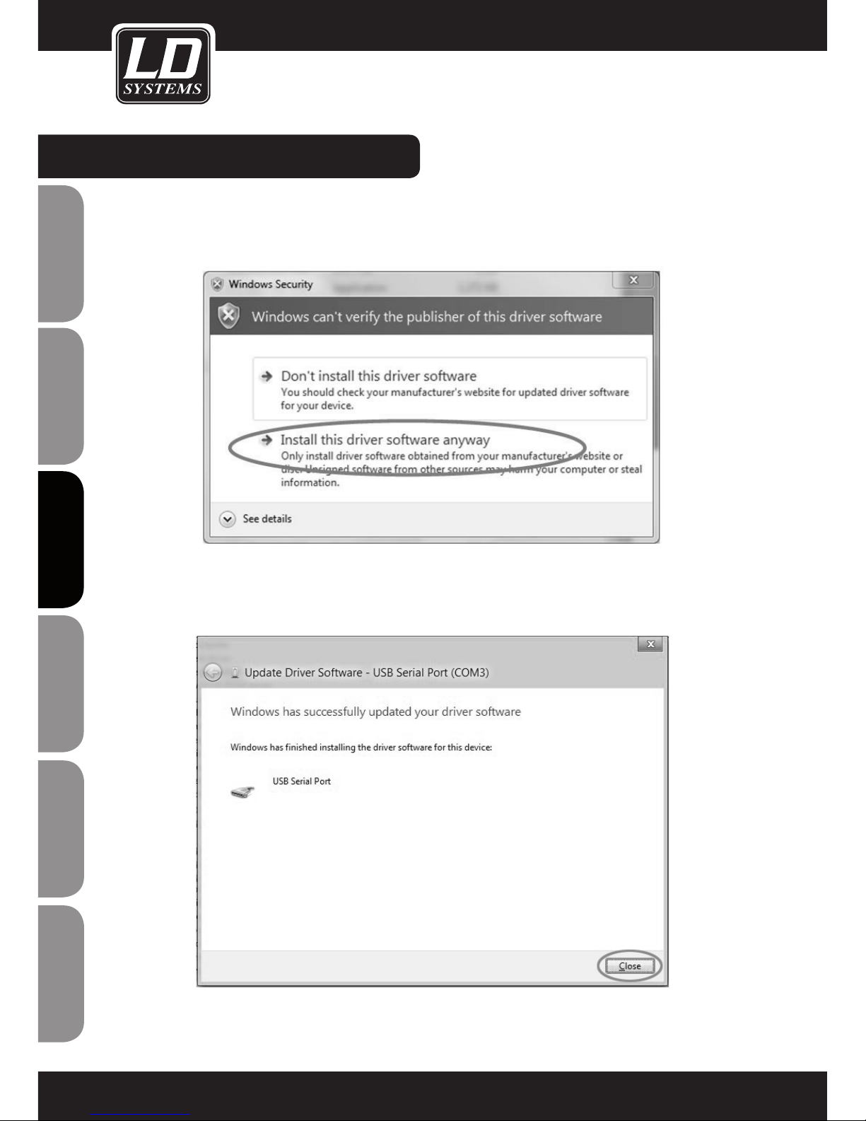
Si un message apparaît, cliquez sur "Installer ces pilotes à la place".
Le pilote est à présent installé. Cliquez sur "Fermer" pour quitter le processus d'installation.
Page 69
ITALIANopoLSKIESpAñoL
FRANCAISFRANCAIS FRANCAISFRANCAIS
FRANCAISDEUTSCHENGLISH
69
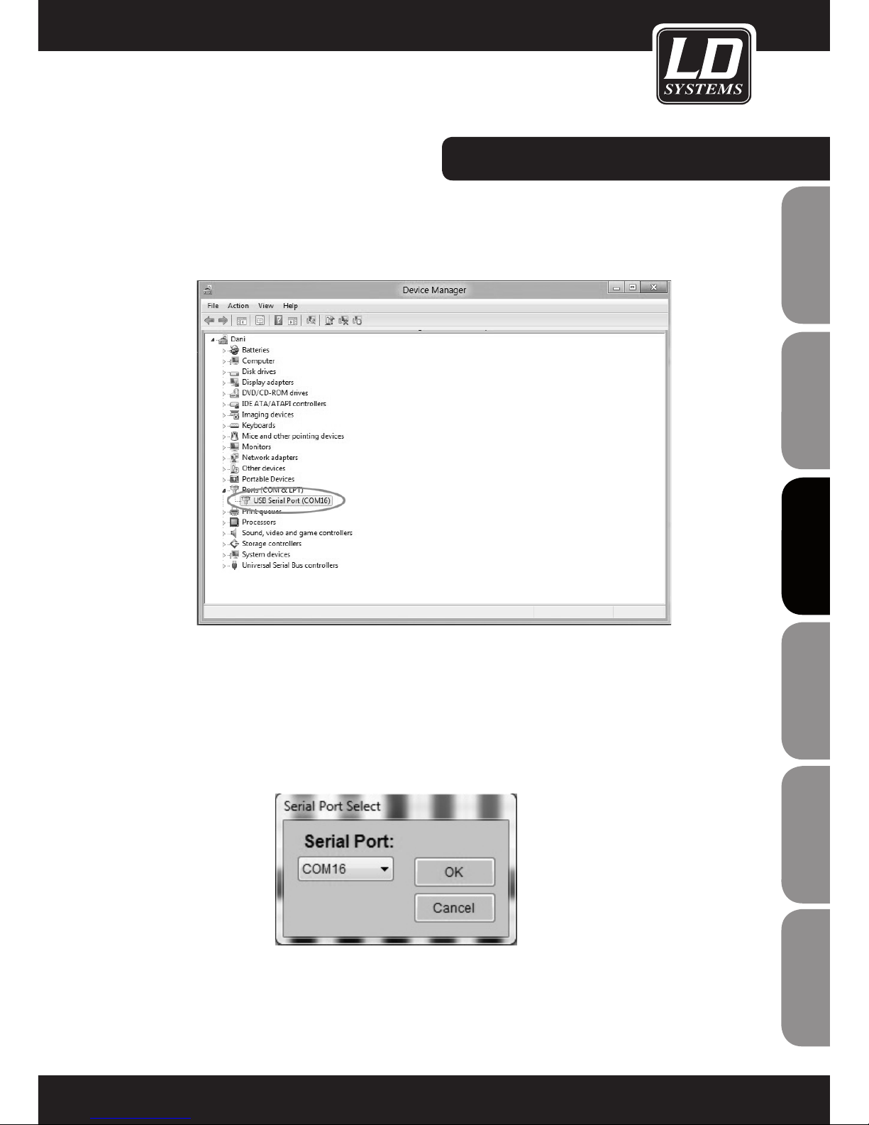
Vous voyez désormais apparaître dans le Gestionnaire de Périphériques le numéro de port COM du "port série USB".
Astuce: Le numéro de port COM du "port série USB" doit être compris entre 1 et 16.
Reliez le HUB CONTRÔLEUR WIN42 au convertisseur USB vers RS485, via le câble RJ45 livré, puis lancez le logiciel WIN42 CONTROL CENTER. Choisissez l'élément "Communication" dans le menu Tools, puis vérifiez que les numéros des connecteurs "Port
série USB" correspondent à ceux des ports apparaissant dans le logiciel WIN42 CONTROL CENTER (dans notre exemple, COM16).
INSTALLATION PILOTES :
Page 70
ENGLISHDEUTSCHFRANCAIS
FRANCAISFRANCAIS FRANCAISFRANCAIS
ESpAñoLpoLSKIITALIANo
70
CONNEXION DU HUB CONTRÔLEURS WIN42 :
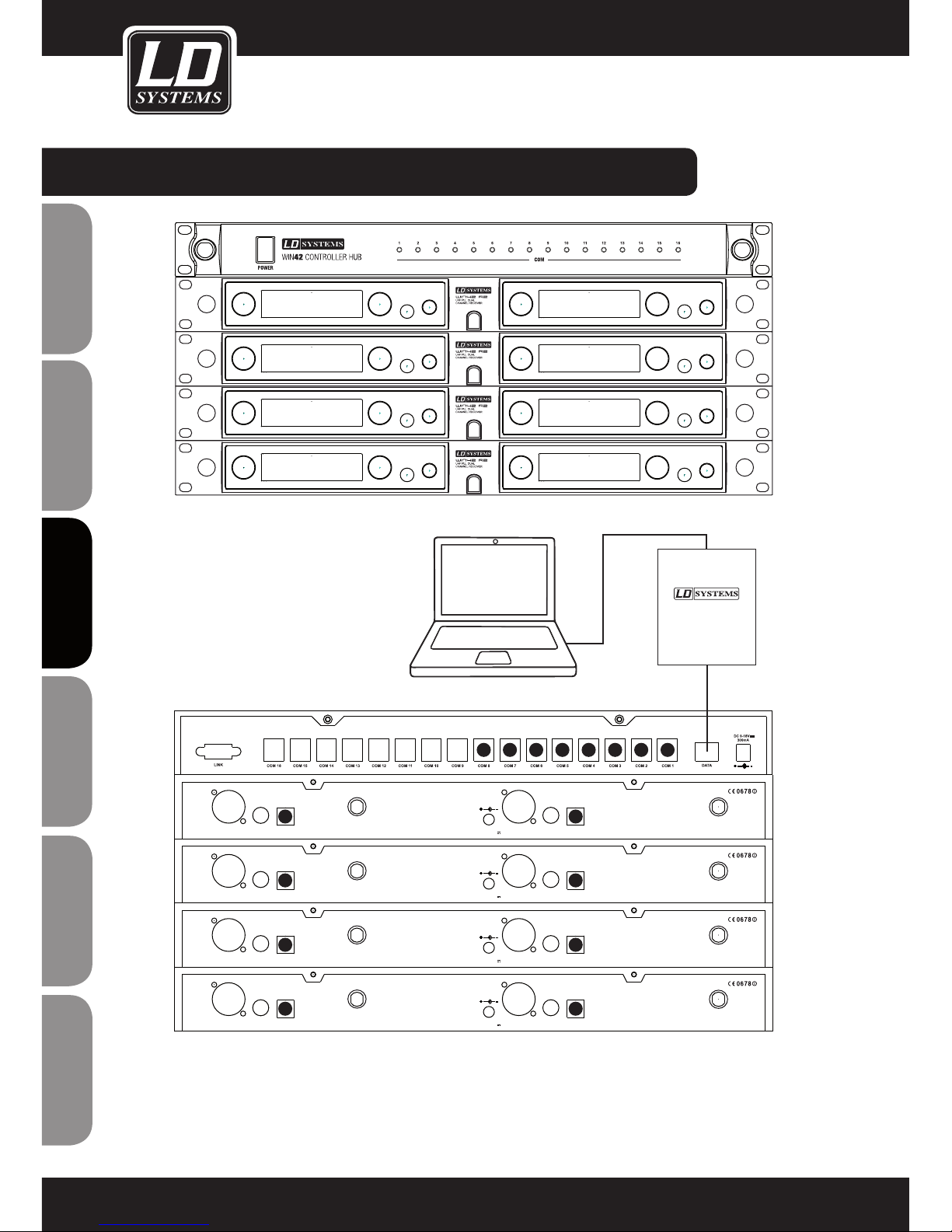
Astuce: Les câbles (16 sont livrés) pour relier le HUB CONTRÔLEUR WIN42 aux récepteurs WIN42 possèdent des connecteurs
de taille différente. Le plus gros connecteur va dans les ports COM (1 à 16) du HUB CONTRÔLEUR WIN42 ; le plus petit, dans la
sortie Data des récepteurs WIN42.
CHANNEL2
XLR BALANCED
UNBAL
OUTPUT
Data Output
ANTENNA-AANTENNA-B
CHANNEL1
XLR BALANCED
D.C 12-18V
1000mA
UNBAL
OUTPUT
Data Output
CHANNEL2
XLR BALANCED
UNBAL
OUTPUT
Data Output
ANTENNA-AANTENNA-B
CHANNEL1
XLR BALANCED
D.C 12-18V
1000mA
UNBAL
OUTPUT
Data Output
CHANNEL2
XLR BALANCED
UNBAL
OUTPUT
Data Output
ANTENNA-AANTENNA-B
CHANNEL1
XLR BALANCED
D.C 12-18V
1000mA
UNBAL
OUTPUT
Data Output
CHANNEL2
XLR BALANCED
UNBAL
OUTPUT
Data Output
ANTENNA-AANTENNA-B
CHANNEL1
XLR BALANCED
D.C 12-18V
1000mA
UNBAL
OUTPUT
Data Output
1
1
3
5
7
2
4
682345678
USB RS485
DATA CONVERTER
DATA
USB
Page 71
ITALIANopoLSKIESpAñoL
FRANCAISFRANCAIS FRANCAISFRANCAIS
FRANCAISDEUTSCHENGLISH
71
INFOS RÉCEPTEUR (RECEIVER INFO).
1
NAME
Cliquez ici pour entrer le nom attribué au
récepteur.
2
GROUP/CHANNEL
Cliquez ici pour entrer le numéro du groupe de
fréquences et le numéro du canal.
3
FREQUENCY
Valeur, en clair, correspondant au groupe et au
canal entrés en (2).
4
ADDRESS CODE
Cliquez ici pour attribuer l'adresse du récepteur
(de 0 à 224)
5
SQUELCH
Cliquez ici pour régler le Squelch sur le récepteur
(trois positions : Low/Mid/High).
6
VALEUR DE VOLUME DU RÉCEPTEUR (03-48)
BATTERY INFO
7
VISUALISATION DE L'ÉTAT DES PILES (DE 0 À
100%).
Lorsque les piles de l'émetteur atteignent un
stade critique, la mention "LOW" apparaît.
RF INFO
8
VISUALISATION DU NIVEAU HF "VU"PAR LE
RÉCEPTEUR.
Le récepteur actif du système Diversity est indiqué
par la lettre A ou B.
AF INFO
9
VISUALISATION DU NIVEAU DU SIGNAL AUDIO
SUR LE RÉCEPTEUR.
10
VISUALISATION DU STATUT DE MUTE SUR LE
RÉCEPTEUR.
11
EQ
Cliquez ici pour modifier le réglage de l'égaliseur
sur le récepteur (Flat = neutre, Lowcut =
coupe-bas, Lowcut+Highboost = coupe-bas +
accentuation des aigus, Highboost = accentuation
des aigus)
UTILISATION DU LOGICIEL WIN42 CONTROL CENTER :
1
2
3
4
5
6
7
8
9
10
11
Page 72
ENGLISHDEUTSCHFRANCAIS
FRANCAISFRANCAIS FRANCAISFRANCAIS
ESpAñoLpoLSKIITALIANo
72
MÉMORISATION/RAPPEL DES PARAMÈTRES
Tous les paramètres gérés dans la fenêtre principale peuvent être mémorisés sur votre ordinateur, pour rappel
ultérieur.
Choisissez l'élément de menu Open Setting ou Save Setting dans le menu File dans la fenêtre principale.
ENVIRONMENT SCAN
La fonction Environment Scan permet d'explorer tout le spectre de fréquences couvert par le système WIN42, ce
qui facilité le repérage de fréquences HF libres.
Veuillez suivre ces instructions point par point afin d'utiliser au mieux les possibilités fonctionnelles du logiciel.
Sélectionnez la fonction Environment Scan dans le menu Tools.
UTILISATION DU LOGICIEL WIN42 CONTROL CENTER :
Page 73
ITALIANopoLSKIESpAñoL
FRANCAISFRANCAIS FRANCAISFRANCAIS
FRANCAISDEUTSCHENGLISH
73
Voici les fonctions disponibles dans la fenêtre Environment Scan (cette fenêtre est donnée à titre d'exemple
uniquement)
1
6
7
8
9
3
5
2
4
MENU SCAN
1
PORT
Choisissez le port d'un des récepteurs connectés, celui sur lequel vous désirez lancer le scan. Attention:
Pendans toute la durée de Scan, ce récepteur sera inutilisable.
2
START SCAN
Lance le Scan. Le récepteur défini par le choix du port explore alors le spectre HF. L'intensité de réception
est visualisée dans le graphique. La procédure peut prendre quelques minutes.
Si la procédure de scan ne peut être lancée, la mention "Scan Timeout" apparaît. Dans ce cas, assurez-vous
que vous avez choisi le bon port (1), que le récepteur est correctement connecté et qu'il fonctionne.
3
STOP
Arrête la procédure de Scan.
4
SAVE PIC
Cliquez ici pour enregistrer la représentation du spectre HF issue du scan sous forme de fichier graphique
(*.jpg) sur votre ordinateur.
5
SCAN TABLE
Cliquez ici pour enregistrer la représentation du spectre HF issue du scan sous forme de tableau, et pour
attribuer les fréquences libres aux récepteurs connectés. Voir également la section "Scan Table" ci après.
6
SHOW GRID
Affiche/masque la grille de coordonnées dans la représentation graphique.
UTILISATION DU LOGICIEL WIN42 CONTROL CENTER :
Page 74
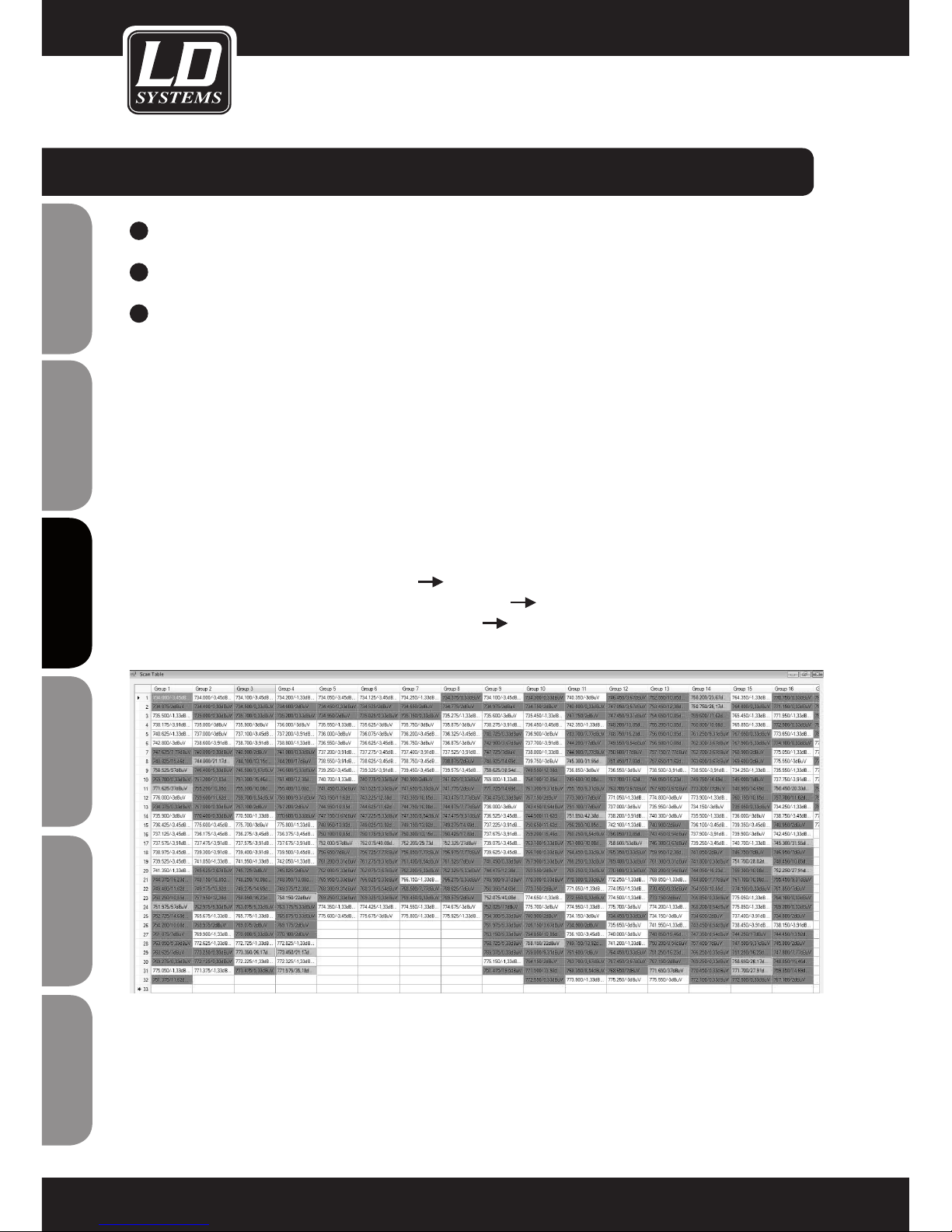
ENGLISHDEUTSCHFRANCAIS
FRANCAISFRANCAIS FRANCAISFRANCAIS
ESpAñoLpoLSKIITALIANo
74
7
ZOOM IN
Cliquez ici pour agrandir une partie de la représentation. Délimitez avec la souris la partie à agrandir.
8
AUTO COORDINATE
Cliquez ici pour activer/désactiver la correspondance automatique des coordonnées.
9
DEFAULT COORDINATE
Cliquez ici pour désactiver le Zoom et revenir à la visualisation globale du graphique.
SCAN TABLE
(cette fenêtre est donnée à titre d'exemple)
Cette représentation permet de trouver des fréquences libres et d'envoyer leurs valeurs aux récepteurs
connectés.
Lancez la procédure Environment Scan comme décrit précédemment, puis cliquez sur Scan Table pour
visualiser les données issues du scan sous forme de tableau. Vous trouverez ici tous les groupes de fréquences
disponibles, avec les valeurs de fréquences correspondantes. Les résultats de la procédure Environment Scan
apparaissent sous forme de valeur de champ mesurée pour chaque fréquence. Les fréquences disponibles dans
le groupe souhaité sont repérées en couleur.
Blanc : Niveau de réception 0 dBuV ou inférieur fréquence libre
Jaune : Niveau de réception compris entre 0 dBuV et 20 dBuV Fréquence probablement occupée
Rouge : Niveau de réception supérieur ou égal à 20 dBuV Fréquence occupée
Pour enregistrer le tableau Scan, cliquez sur le bouton Save situé en bas à droite du tableau ; vous pourrez ainsi
retrouver facilement ces résultats ultérieurement.
Pour rappeler un tableau Scan déjà enregistré, il suffit de choisir l'élément de menu Open RF File dans le menu
File de la fenêtre principale.
UTILISATION DU LOGICIEL WIN42 CONTROL CENTER :
Page 75
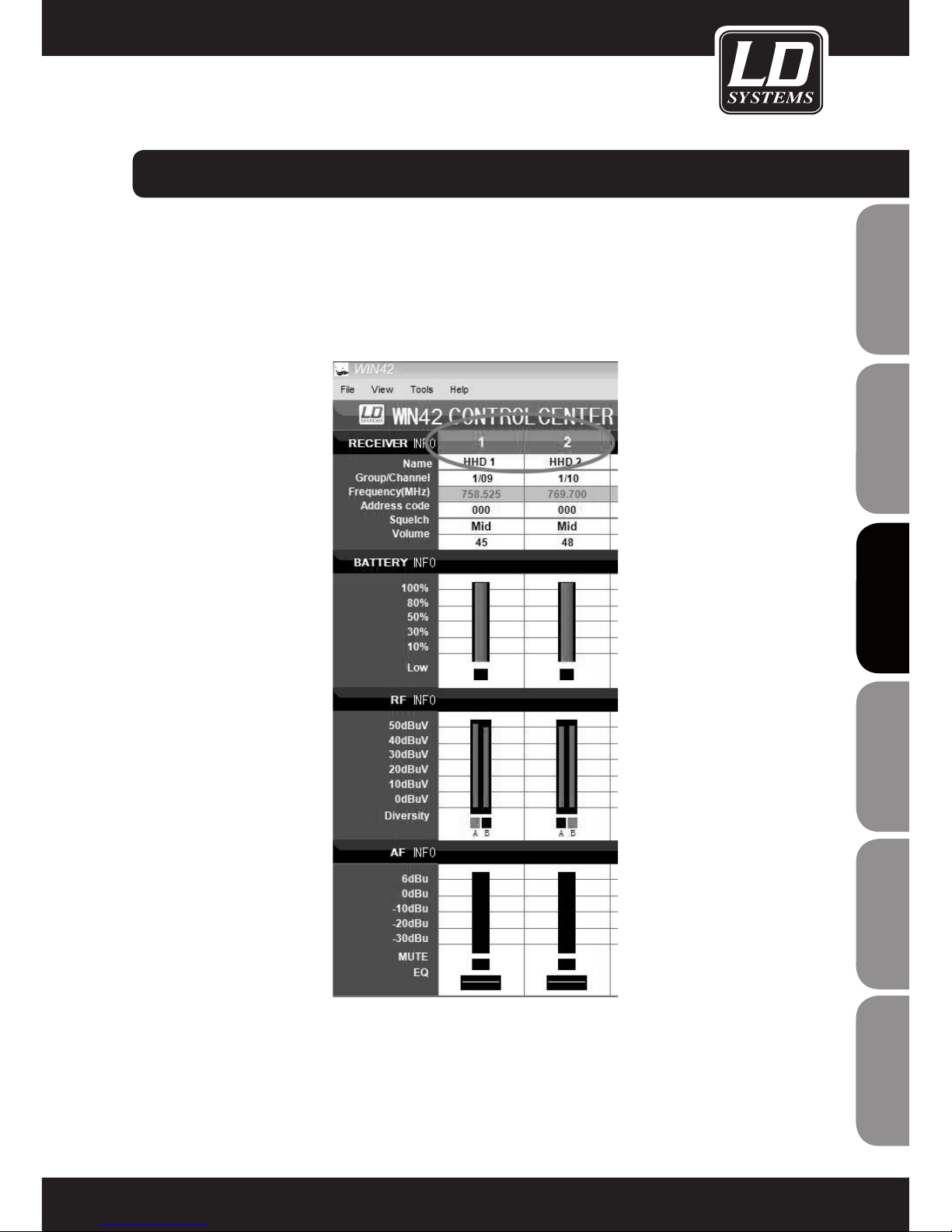
ITALIANopoLSKIESpAñoL
FRANCAISFRANCAIS FRANCAISFRANCAIS
FRANCAISDEUTSCHENGLISH
75
ATTRIBUTION DES FRÉQUENCES
Pour attribuer une fréquence à un des émetteurs connectés, cliquez sur cette fréquence. Vous revenez alors
automatiquement à la représentation principale.
Les numéros de récepteurs clignotent afin de signaler auxquels vous pouvez attribuer la fréquence choisie.
Choisissez l'émetteur, en cliquant sur son numéro. La fréquence choisie dans le tableau Table Scan est alors
attribuée au récepteur désiré.
Répétez la procédure jusqu'à assignation des fréquences à tous les récepteurs disponibles. Pour synchroniser
ensuite les récepteurs programmés avec leurs émetteurs, utilisez la fonction Sync de l'émetteur ou entrez
manuellement les fréquences sur les émetteurs.
UTILISATION DU LOGICIEL WIN42 CONTROL CENTER :
Page 76
ENGLISHDEUTSCHFRANCAIS
FRANCAISFRANCAIS FRANCAISFRANCAIS
ESpAñoLpoLSKIITALIANo
76
Type de produit Contrôleur pour système HF WIN42
Type Interface pour pilotage/suivi par logiciel
Nombre de systèmes HF pilotables : 16
Indicateurs 16 x LED
Tension d'utilisation : 9 à 18 V continu, intensité consommée 300 mA
Largeur 482 mm
Hauteur 44 mm
Profondeur 160 mm
Poids: 1850 g
Accessoires inclus: Convertisseur USB vers RS485, 1 x câble USB, 16 x câbles RJ11, 1 x câble RJ45, 1
x bloc secteur, CD-ROM
CARACTÉRISTIQUES TECHNIQUES :
Page 77
ITALIANopoLSKIESpAñoL
FRANCAISFRANCAIS FRANCAISFRANCAIS
FRANCAISDEUTSCHENGLISH
77
GARANTIE LIMITÉE:
Cette garantie limitée s’applique aux produits de la marque Adam Hall, LD Systems, LD Premium, Defender, Palmer,
Cameo et Eminence.
Les droits inhérents à la garantie légale vis-à-vis du revendeur ne sont pas affectés par cette garantie. En fait elle
justifie d’une garantie supplémentaire indépendante auprès de la société Adam Hall.
La société Adam Hall garantit que le produit que vous avez acheté Adam Hall ou à l’un de ses revendeurs officiels,
est exempt de défaut matériel et d’usinage pour une durée de 2 ans (ou 5 ans pour les produits Palmer) à partir de
la date d’achat, lorsqu’il est utilisé dans des conditions normales.
La période de garantie limitée débute le jour de l’achat du produit. Pour bénéficier de cette garantie vous devez
produire une preuve d’achat sur laquelle figure la date d’achat du produit (ex : ticket de caisse daté, bon de
livraison daté…). Si un produit d´une des marques citées ci-dessus venait à nécessiter une réparation durant la
période de garantie limitée, vous aurez alors le droit de bénéficier des services de la garantie selon les termes et
conditions mentionnés par ce document.
Cette garantie limitée ne s’applique qu’à l’acheteur initial de ce produit Adam Hall et ne peut être en aucun cas
transférée à un tiers devenu propriétaire du produit. Durant la période de garantie limitée, Adam Hall s‘engage
à réparer ou remplacer les pièces défectueuses du produit. Toutes les pièces ou éléments démontés lors d‘une
réparation par Adam Hall deviennent la propriété d‘Adam Hall.
Dans le cas improbable d´un défaut récurrent, Adam Hall peut, à sa discrétion, décider de vous fournir un produit
de remplacement de son choix, dont les capacités techniques sont au moins équivalentes à celles de votre produit
initial.
Adam Hall ne garantit pas que le fonctionnement de ce produit sera exempt d‘erreur ou ininterrompu. Adam Hall ne
peut pas être rendu responsable des dégâts résultant de votre manquement à suivre les instructions d‘utilisation
fournies avec votre produit.
Cette garantie limitée ne s‘applique pas,
- aux pièces d‘usure (ex: piles)
- aux produits dont le numéro de série a été effacé ou aux produits endommagés ou rendus défectueux par
accident
- dans le cas d‘une utilisation non conforme aux conditions normales d‘utilisation, dans le cas d‘abus ou
toute autre cause externe
- dans le cas d‘un usage du produit en dehors des paramètres d‘utilisation stipulés dans la documentation
fournie avec le produit
- dans le cas de l‘usage de pièces de remplacement n‘étant pas fabriquées ou vendues par Adam Hall
- dans le cas d‘une modification du produit ou d‘une réparation par quiconque autre qu‘Adam Hall
Ces termes et conditions constituent l‘accord de garantie complet et exclusif entre vous et Adam Hall concernant
le produit de la marque Adam Hall que vous vous êtes procuré.
DECLARATIONS DU FABRICANT :
Page 78
ENGLISHDEUTSCHFRANCAIS
FRANCAISFRANCAIS FRANCAISFRANCAIS
ESpAñoLpoLSKIITALIANo
78
DECLARATIONS DU FABRICANT :
LIMITATION OF LIABILITY
Si votre produit Adam Hall devait ne pas fonctionner correctement, votre seul et unique dédommagement sera
la réparation du produit ou son remplacement. La responsabilité maximale imputable à Adam Hall dans le cadre
de cette garantie limitée se limite au montant le plus bas. Ce montant découle du prix d’achat du produit ou
bien du coût de la réparation ou des pièces de remplacement qui sont tombés en panne dans des conditions
d’utilisation normales.
Adam Hall n’est pas responsable des dommages causés par le produit ou par un dysfonctionnement du produit,
y compris les pertes de profits, les pertes d’épargne, et les conséquences inhérentes à ces dommages. La
responsabilité d’Adam Hall ne peut pas être engagée dans le cas d’une réclamation par un tiers ou dans le cas
d’une réclamation émanant de l’acheteur initial pour le compte d’un tiers.
Cette limitation de responsabilité est valable indépendamment du fait que les dommages commis fassent l’objet
de poursuites judiciaires, qu’ils fassent l’objet de réclamation (y compris pour négligence), de réclamations
contractuelles ou tout autre réclamation. Cette limitation de responsabilité ne peut être amendée ou dérogée par
quiconque. Elle est effective même si vous aviez avisé Adam Hall ou l’un de ses représentants officiels de la possibilité d’un tel dommage. Toutefois cette limitation de responsabilité est sans effet dans le cas de réclamations
pour dommages corporels.
Cette garantie limitée vous confère des droits légaux spécifiques. Selon votre pays, ou l’État dans lequel vous
vous trouvez, il est possible que vous disposiez d’autres droits. Veuillez consulter les lois applicables dans votre
pays ou votre État pour déterminer l’ensemble de vos droits.
FAIRE FONCTIONNER LA GARANTIE
Pour faire fonctionner la garantie sur ce produit, veuillez contacter Adam Hall ou le revendeur agréé auquel vous
avez acheté le produit.
ELIMINATION CORRECTE DES DÉCHETS (DÉCHETS ÉLECTROMÉNAGERS)
(Applicable dans l’Union Européenne et dans les autres pays européens disposant d’un système de tri des déchets)
Ce signe figurant sur le produit, ou dans la brochure jointe au produit, indique qu’il ne doit pas être jeté dans le
même bac à ordures que les déchets ménagers classiques lorsqu’il arrive en fin de vie. Pour écarter les risques
de pollution de l’environnement ou les risques d’intoxication humaine dûes à un mauvais traitement des déchets,
veuillez séparer ce produit des autres types de déchets. Il sera ainsi inséré dans la boucle du recyclage et ces
composants pourront être traités puis éventuellement réutilisés.
Nous recommandons aux particuliers de contacter leur revendeur local ou les autorités locales pour s’informer
de la meilleure façon de traiter les déchets électroménagers.
Les professionnels doivent contacter leur fournisseur et examiner avec lui les termes et conditions de leur
contrat d’achat. Ce produit ne doit pas être mélangé aux déchets industriels.
Page 79
ITALIANopoLSKIESpAñoL
FRANCAISFRANCAIS FRANCAISFRANCAIS
FRANCAISDEUTSCHENGLISH
79
DECLARATION WEEE
Votre produit LD-Systems a été développé et fabriqué avec des matériaux et des composants de haute qualité,
qui peuvent être recyclés et/ou réutilisés. Ce symbole indique que les appareils électriques et électroniques, à la
fin de leur durée de vie opérationnelle, doivent être gérés séparément des déchets ordinaires.
Veuillez apporter ce produit au point de collecte ou centre de recyclage local prévu pour de tels appareils. Vous
contribuerez ainsi à la protection de l'environnement dans lequel nous vivons tous.
BATTERIES ET ACCUMULATEURS
Les piles ou batteries rechargeable livrées avec l'appareil sont recyclables. Veuillez les jeter dans un bac à
déchets spécial, ou déposez-les chez votre revendeur spécialisé. Pour une meilleure protection de l'environnement, ne jetez les piles que lorsqu'elles sont épuisées.
ÉCOLOGIE ET ÉCONOMIES D'ÉNERGIE :
Économiser l'électricité contribue à la protection de l'environnement. Pensez à éteindre les appareils électriques
dès que vous ne vous en servez pas. Pour éviter le gaspillage d'énergie en mode Standby (veille), débranchez le
cordon secteur de la prise murale lorsqu'un appareil n'est pas utilisé.
Adam Hall GmbH, tous droits réservés. Les caractéristiques techniques et les fonctions disponibles sur le produit
sont sujettes à modifications. La photocopie, la traduction et toute forme de copie, partielle ou intégrale, de ce
manuel utilisateur sont interdites.
DECLARATIONS DU FABRICANT :
Page 80
ENGLISHDEUTSCHFRANCAIS
FRANCAISFRANCAIS FRANCAISFRANCAIS
ESpAñoLpoLSKIITALIANo
80
Gracias por elegir LD-Systems!
Este producto se ha diseñado para ofrecer una fiabilidad y durabilidad óptima. Los productos de LD-Systems se
caracterizan por su gran calidad, avalada por el prestigio de la marca y una dilatada experiencia como fabricante.
Le rogamos que lea atentamente estas instrucciones para familiarizarse rápidamente con este producto LDSystems y aprovechar al máximo todas las funciones.
Si desea obtener información sobre LD-Systems, visite nuestro sitio web WWW.LD-SYSTEMS.COM
Introducción
El WIN42HUB de LD Systems y el software asociado WIN42 CONTROL CENTER permiten controlar y monitorizar
hasta 16 equipos inalámbricos WIN42. Mediante unos gráficos sencillos podrá controlar la frecuencia, el estado
de la batería, la señal de radio, el nivel de audio y otros datos de cada equipo WIN42 conectado. Además, el
software ofrece una función de barrido (Environment Scan) para buscar las frecuencias libres.
Page 81
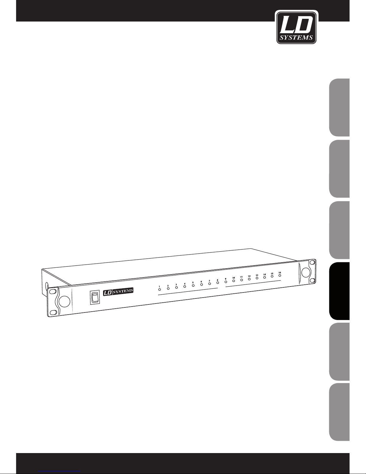
ITALIANOPOLSKIESPAÑOL
FRANCAISFRANCAIS FRANCAISFRANCAIS
FRANCAISDEUTSCHENGLISH
81
POWER
WIN42 CONTROLLER HUB
COM
LD WIN42HUB
WIN42HUB
Page 82
ENGLISHDEUTSCHFRANCAIS
FRANCAISFRANCAIS FRANCAISFRANCAIS
ESpAñoLpoLSKIITALIANo
82
1. Lea detenidamente este manual.
2. Guarde el manual para poder consultarlo en el futuro.
3. Siga las instrucciones del manual.
4. Tenga en cuenta las advertencias de seguridad. No quite las instrucciones de seguridad ni cualquier otra
información indicada en el equipo.
5. Utilice el equipo únicamente según la finalidad prevista.
6. Emplee un soporte y/o sistema de fijación estables y adecuados cuando instale el equipo de forma permanente. Asegúrese de que los soportes para pared están firmemente fijados. Asegúrese de que el equipo está
instalado de forma segura y no se puede caer.
7. Al instalar el equipo, respete las normas de seguridad aplicables en su país.
8. Evite colocar el equipo cerca de radiadores, acumuladores de calor o cualquier otra fuente de calor. Asegúrese
de que el equipo dispone de la suficiente ventilación y de que no se sobrecalentará.
9. No coloque velas encendidas, ni otras fuentes de llama, sobre el equipo.
10. No tape las rejillas de ventilación.
11. No utilice el equipo cerca del agua. No exponga este equipo a materiales, líquidos o gases inflamables.
12. Asegúrese de que el equipo no quede expuesto a goteras o salpicaduras de agua. No coloque recipientes
llenos de líquido, como floreros o copas, sobre el equipo.
13. Asegúrese de que no se caiga ningún objeto sobre el equipo.
14. Emplee el equipo únicamente con los accesorios recomendados por el fabricante.
15. ADVERTENCIA: Si el equipo tiene un conector de tierra, deberá enchufarse a una toma eléctrica con conexión
de protección a tierra. No desactivar nunca esta conexión de protección a tierra del cable eléctrico.
16. Si el equipo ha estado expuesto a un cambio brusco de temperatura (por ejemplo, después del transporte),
no lo encienda inmediatamente. La condensación o la humedad podrían dañar el equipo. Deje el equipo apagado hasta que haya alcanzado la temperatura ambiente.
17. No abra el equipo ni intente modificarlo.
18. Antes de conectar el equipo a la red eléctrica, asegúrese de que la tensión y frecuencia son las mismas
que los valores indicados en el equipo (ver etiqueta de especificaciones). Si el equipo dispone de un selector de
tensión, antes de enchufarlo a la red eléctrica, asegúrese de que el valor seleccionado coincide con la tensión de
suministro.
Si el enchufe no encaja en la toma eléctrica, consulte a un electricista.
19. Asegúrese de que el cable eléctrico no está pinzado. Evite que el cable resulte pellizcado, sobre todo en los
extremos de conexión al equipo y en la toma eléctrica.
20. Para evitar accidentes y daños personales, compruebe que en toda la longitud del cableado no hay peligro de
que provoque una caída, por ejemplo.
21. Al conectar el equipo, asegúrese de que haya una toma eléctrica accesible.
Desenchufe el equipo de la toma eléctrica cuando no esté en uso o antes de limpiarlo. Para desenchufarlo
tire del enchufe, no del cable eléctrico. No tocar el cable eléctrico ni el adaptador de corriente con las manos
húmedas.
22. Evite encender y apagar el equipo en cortos intervalos de tiempo, ya que se reduce así la vida útil del equipo.
23. IMPORTANTE: Al sustituir los fusibles, utilice únicamente fusibles del mismo tipo y características. Si el
fusible se fundiera continuamente, póngase en contacto con un servicio técnico autorizado.
24. Para desconectar completamente el equipo de la tensión eléctrica, desenchúfelo de la toma eléctrica.
25. Si el equipo dispone de un enchufe eléctrico Volex, deberá desbloquearse el Volex del equipo para
MEDIDAS DE SEGURIDAD:
Page 83
ITALIANOPOLSKIESPAÑOL
FRANCAISFRANCAIS FRANCAISFRANCAIS
FRANCAISDEUTSCHENGLISH
8383
desenchufarlo. Esto implica que un tirón en el cable eléctrico puede desplazar el equipo y provocar daños personales o materiales. Por tanto, asegúrese de instalar los cables con sumo cuidado.
26. Si es probable que caiga un rayo por una tormenta eléctrica o si no va a emplear el equipo durante mucho
tiempo, desenchufe el cable eléctrico.
27. Al transportar el equipo, para evitar daños personales o materiales, asegúrese de que no se pueda caer
accidentalmente.
28. Si el equipo no funciona correctamente, o si se ha vertido líquido sobre él, o si un objeto ha caído en su
interior o si ha sufrido algún desperfecto, apague inmediatamente el equipo y desenchufe el cable eléctrico.
Únicamente un técnico especialista debe reparar el equipo.
29. Emplee un paño seco para limpiar el equipo.
30. Siga las normas sobre reciclaje existentes en su país. Separe el plástico del papel y cartón.
31. No deje las bolsas de plástico al alcance de los niños.
CAUTION
RISK OF ELECTRIC SHOCK
DO NOT OPEN
MEDIDAS DE SEGURIDAD:
ADVERTENCIA:
Para evitar el riesgo de descarga eléctrica, no retire la tapa (o el panel posterior). Este equipo no contiene piezas
que puedan ser reparadas por el usuario. Para cualquier tarea de mantenimiento o reparación, acuda a un
técnico cualificado.
El símbolo de rayo dentro de un triángulo equilátero advierte al
usuario de la presencia de tensión peligrosa sin aislamiento dentro de la carcasa del producto que
pueden ser de magnitud suficiente como para suponer un riesgo para las personas.
El símbolo de exclamación dentro de un triángulo equilátero advierte al usuario de la existencia de
importantes instrucciones de funcionamiento y mantenimiento (reparaciones) en la documentación
adjunta con el equipo.
ADVERTENCIA: ¡ALTO VOLUMEN!
Este sistema de transmisión se destina a un uso profesional. Por consiguiente, si se aplica a un uso comercial,
estará sujeto a las normas y reglamentos de la Asociación para la prevención de accidentes de su sector profesional. Como fabricante, Adam Hall tiene la obligación de informar formalmente a los usuarios de la existencia de
posibles riesgos para la salud.
Daños auditivos por exposición prolongada a un nivel SPL alto: el altavoz puede generar fácilmente un nivel de
presión sonora (SPL) lo suficientemente elevado como para causar daños auditivos permanentes a los artistas, el
personal de producción y el público. Deben tomarse precauciones para evitar la exposición prolongada a un SPL
de más de 90 dB.
ENGLISH
Page 84
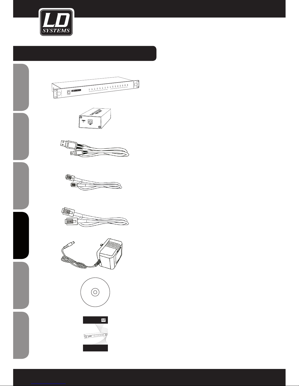
ENGLISHDEUTSCHFRANCAIS
FRANCAISFRANCAIS FRANCAISFRANCAIS
ESpAñoLpoLSKIITALIANo
84
COMPONENTES INCLUIDOS:
1 WIN42 CONTROLLER HUB
1 conversor USB a RS-485 para WIN42
1 cable USB
16 cables RJ11
1 cable RJ45
1 adaptador de corriente
1 CD de software
1 manual de usuario
POWER
WIN42 CONTROLLER HUB
COM
USER´S MANUAL
BEDIENUNGSANLEITUNG
MANUEL D`UTILISATION
MANUAL DE USUARIO
INSTRUKCJA OBSŁUGI
MANUALE D‘ USO
LD WIN42 CONTROLLER HUB
WIN42HUB
POWER
WIN42 CONTROLLER HUB
COM
Page 85
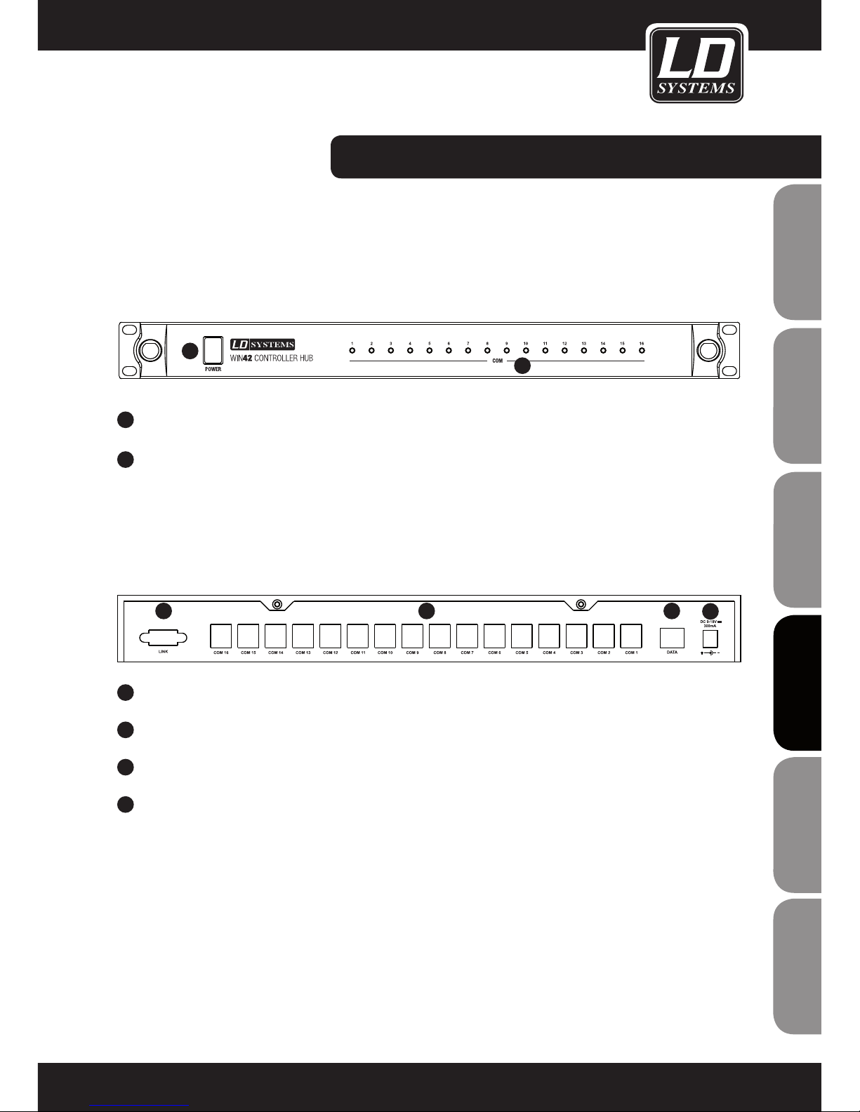
ITALIANOPOLSKIESPAÑOL
FRANCAISFRANCAIS FRANCAISFRANCAIS
FRANCAISDEUTSCHENGLISH
85
PANELES FRONTAL Y POSTERIOR:
1
INTERRUPTOR DE ENCENDIDO/APAGADO
2
INDICADORES LED 1 A 16 PARA 16 RECEPTORES WIN42
1
TOMA PARA EL ADAPTADOR DE CORRIENTE (9 A 18 VDC, 300 MA)
2
CONECTOR DATA PARA EL CONVERSOR DE USB A RS-485
3
CONECTORES COM 1 A 16 PARA LOS RECEPTORES WIN42
4
PUERTO PARA FUTURAS AMPLIACIONES (ACTUALMENTE NO DISPONIBLE)
PANEL FRONTAL
PANEL POSTERIOR
1
1
2
234
Page 86
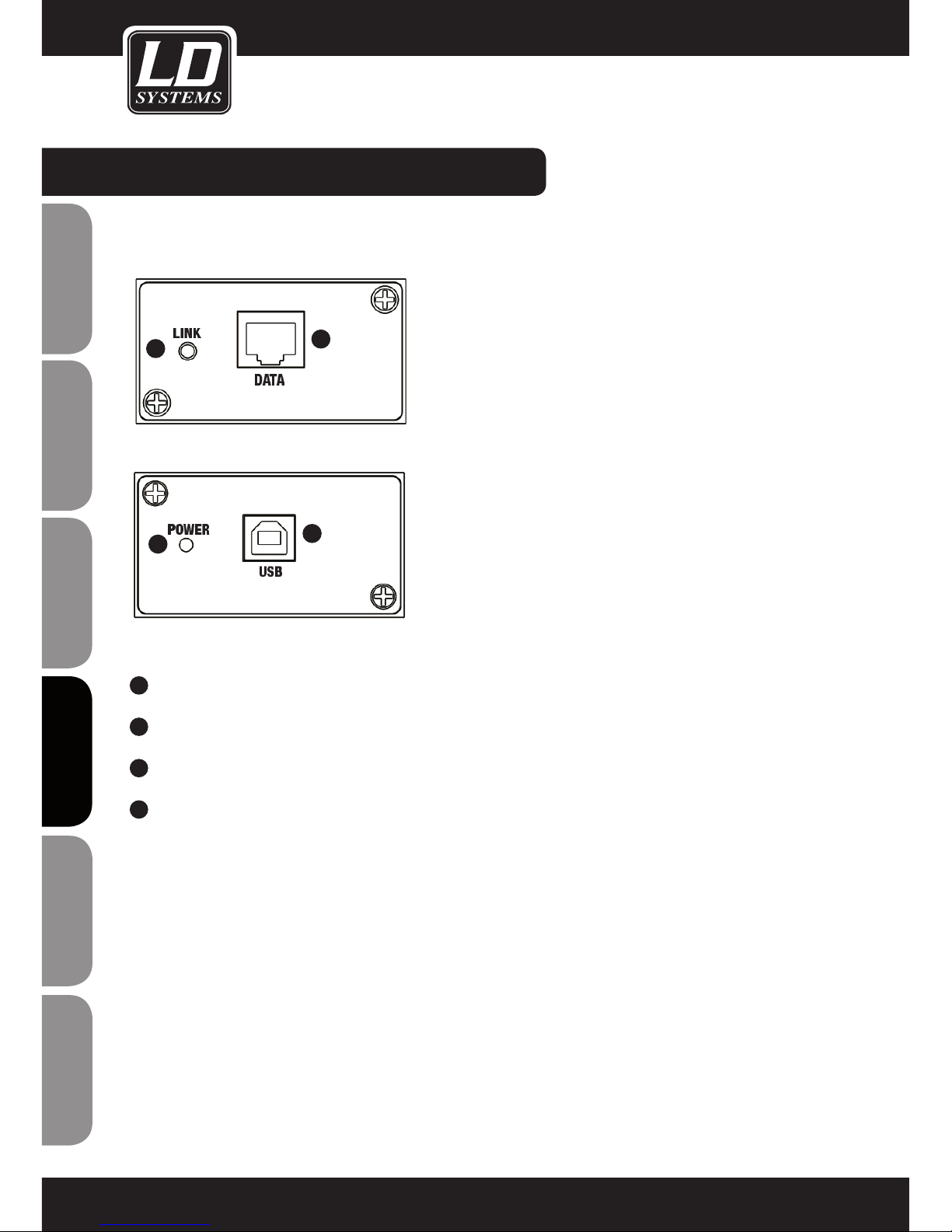
ENGLISHDEUTSCHFRANCAIS
FRANCAISFRANCAIS FRANCAISFRANCAIS
ESpAñoLpoLSKIITALIANo
86
CONVERSOR DE USB A RS-485:
1
CONECTOR RJ45 PARA CONECTAR AL WIN42HUB
2
CONECTOR USB PARA CONECTAR A UN PC CON WINDOWS
3
LED POWER: SE ILUMINA CUANDO EL CONVERSOR ESTÁ CORRECTAMENTE CONECTADO POR USB.
4
LED LINK: SE ILUMINA CUANDO LA CONEXIÓN ENTRE EL CONVERSOR Y EL WIN42HUB ES CORRECTA.
2
1
4
3
Page 87
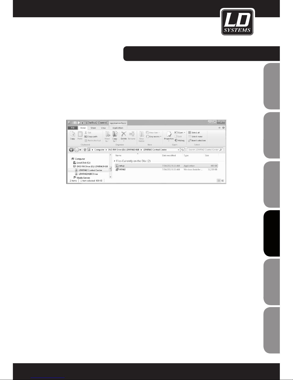
ITALIANOPOLSKIESPAÑOL
FRANCAISFRANCAIS FRANCAISFRANCAIS
FRANCAISDEUTSCHENGLISH
87
INSTALACIÓN DEL SOFTWARE:
REQUISITOS DEL SISTEMA
Para el software WIN42 CONTROL CENTER y los controladores del WIN42 CONTROLLER HUB: Windows XP,
Windows Vista, Windows 7 o Windows 8, un puerto USB 2.0 y una resolución de pantalla mínima recomendada
de 1.366 x 768.
1. Inserte el CD de software suministrado en la unidad óptica del ordenador y, a continuación, abra el disco, haga doble clic en el
archivo "Setup" y siga las instrucciones para instalar el software WIN42 CONTROL CENTER en el ordenador.
Page 88
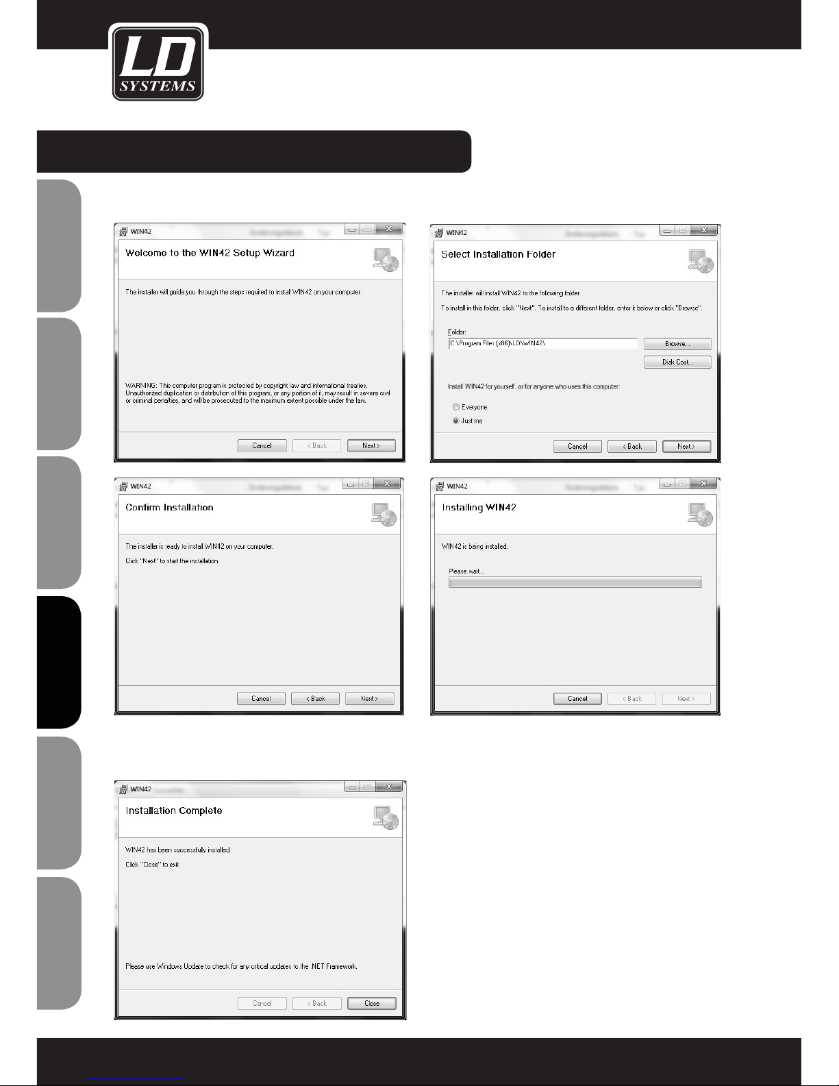
ENGLISHDEUTSCHFRANCAIS
FRANCAISFRANCAIS FRANCAISFRANCAIS
ESpAñoLpoLSKIITALIANo
88
INSTALACIÓN DEL SOFTWARE:
2. Haga clic en el botón "Next" cada vez que se le solicite durante el proceso de instalación.
Haga clic en "Close" para finalizar la instalación.
Page 89
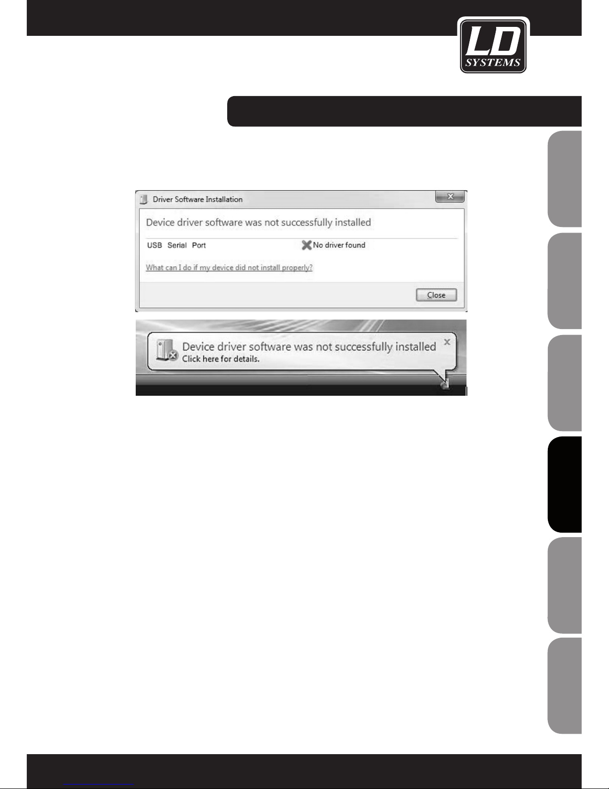
ITALIANOPOLSKIESPAÑOL
FRANCAISFRANCAIS FRANCAISFRANCAIS
FRANCAISDEUTSCHENGLISH
89
Conecte el conversor de USB a RS-485 suministrado a un puerto USB del ordenador.
INSTALACIÓN DEL CONTROLADOR:
Page 90
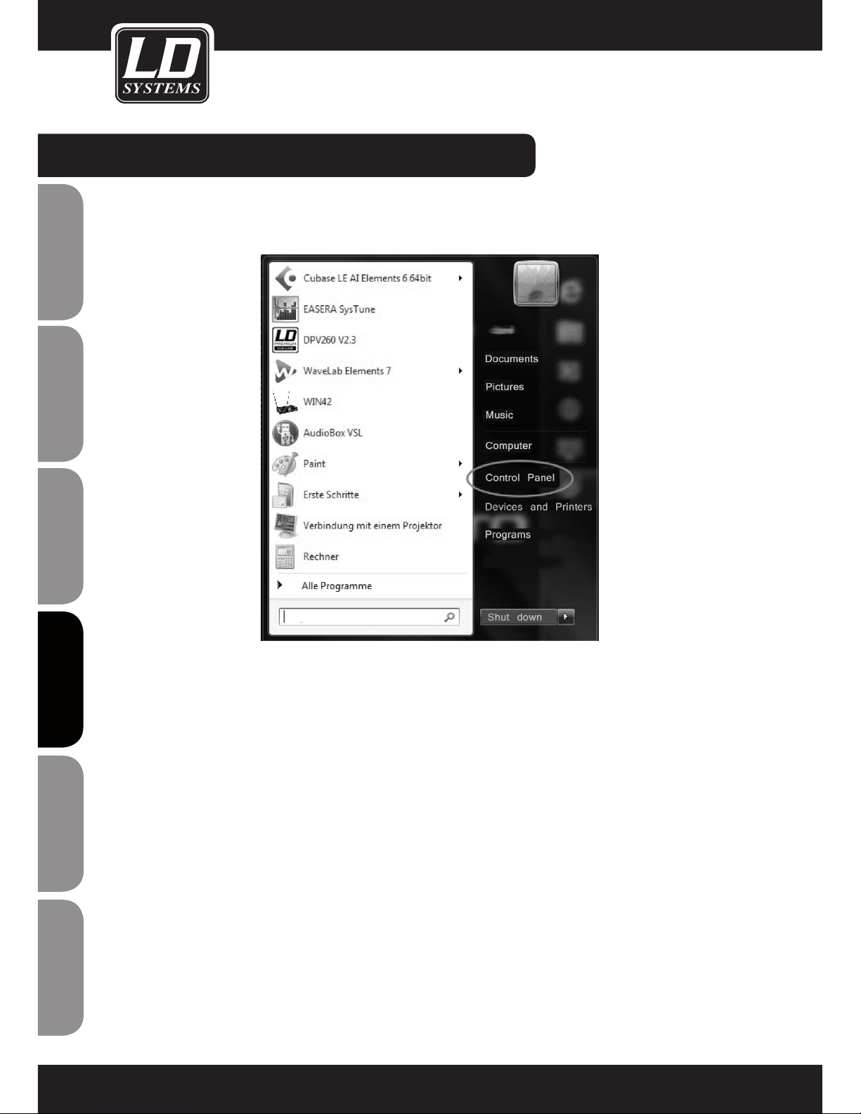
ENGLISHDEUTSCHFRANCAIS
FRANCAISFRANCAIS FRANCAISFRANCAIS
ESpAñoLpoLSKIITALIANo
90
INSTALACIÓN DEL CONTROLADOR:
Si al instalar los controladores se muestra un mensaje del sistema como el de la página anterior, pulse la tecla Windows del
teclado y haga clic en "Panel de control".
Page 91
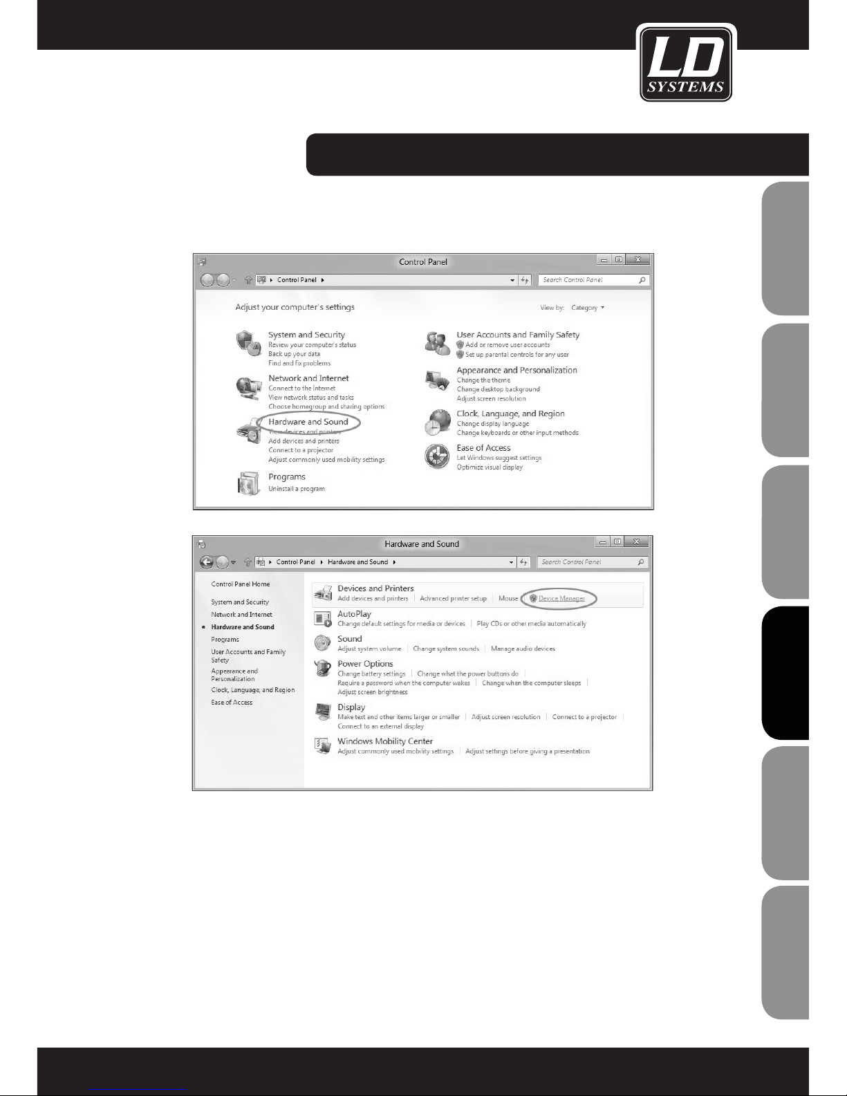
ITALIANOPOLSKIESPAÑOL
FRANCAISFRANCAIS FRANCAISFRANCAIS
FRANCAISDEUTSCHENGLISH
91
Se abrirá la ventana del "Panel de control". Haga clic en "Hardware y sonido" y luego en "Administrador de dispositivos".
INSTALACIÓN DEL CONTROLADOR:
Page 92
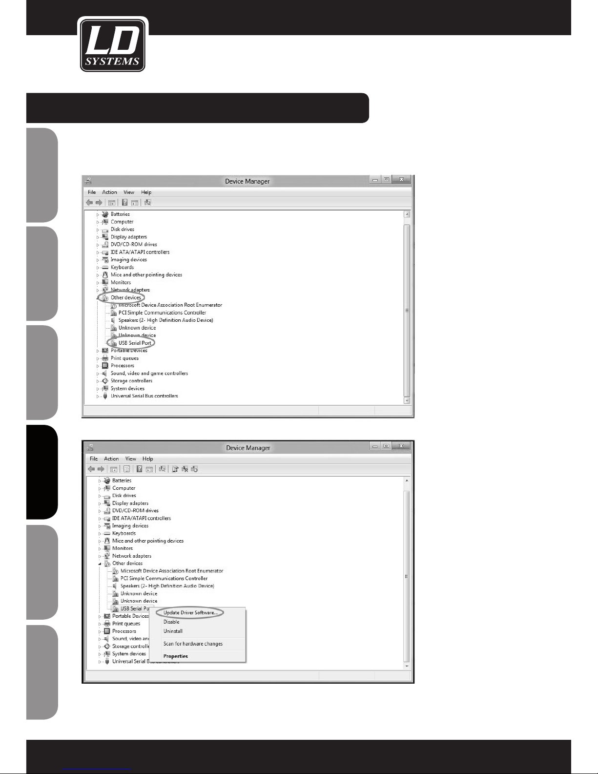
ENGLISHDEUTSCHFRANCAIS
FRANCAISFRANCAIS FRANCAISFRANCAIS
ESpAñoLpoLSKIITALIANo
92
INSTALACIÓN DEL CONTROLADOR:
En la ventana del Administrador de dispositivos haga clic en la flecha de "Otros dispositivos". Haga clic con el botón derecho del
ratón en "USB Serial Port" y seleccione "Actualizar software del controlador".
Page 93
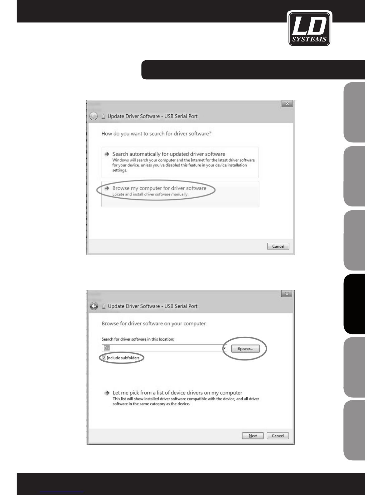
ITALIANOPOLSKIESPAÑOL
FRANCAISFRANCAIS FRANCAISFRANCAIS
FRANCAISDEUTSCHENGLISH
93
Haga clic en "Buscar software de controlador en el equipo".
Seleccione la unidad óptica del ordenador que contiene el CD de software y controladores suministrado, marque la casilla "Incluir
subcarpetas" y haga clic en "Siguiente" para continuar.
INSTALACIÓN DEL CONTROLADOR:
Page 94
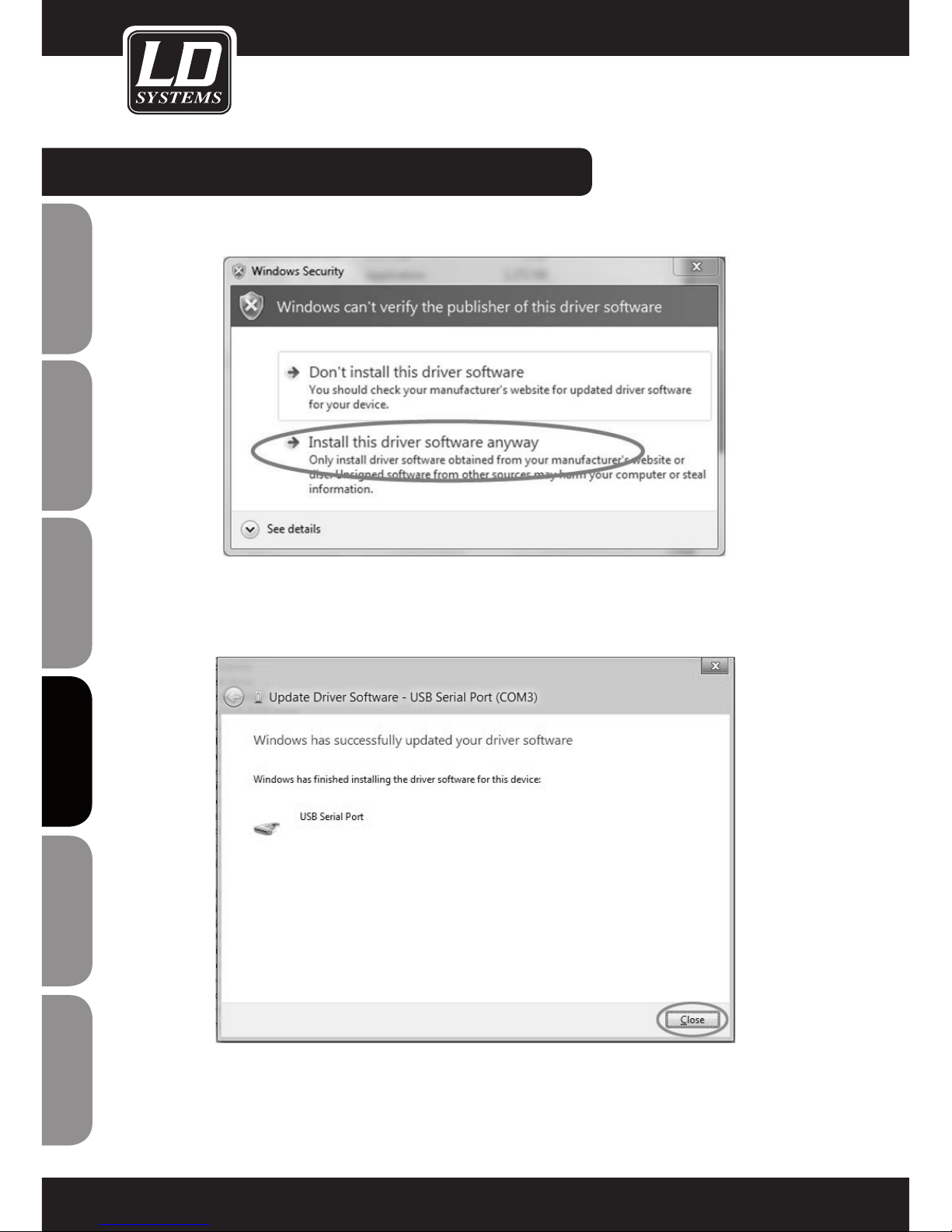
ENGLISHDEUTSCHFRANCAIS
FRANCAISFRANCAIS FRANCAISFRANCAIS
ESpAñoLpoLSKIITALIANo
94
INSTALACIÓN DEL CONTROLADOR:
Si aparece el siguiente mensaje, haga clic en "Instalar este software de controlador de todas formas".
Ya está instalado el controlador. Haga clic en "Cerrar" para salir del asistente.
Page 95
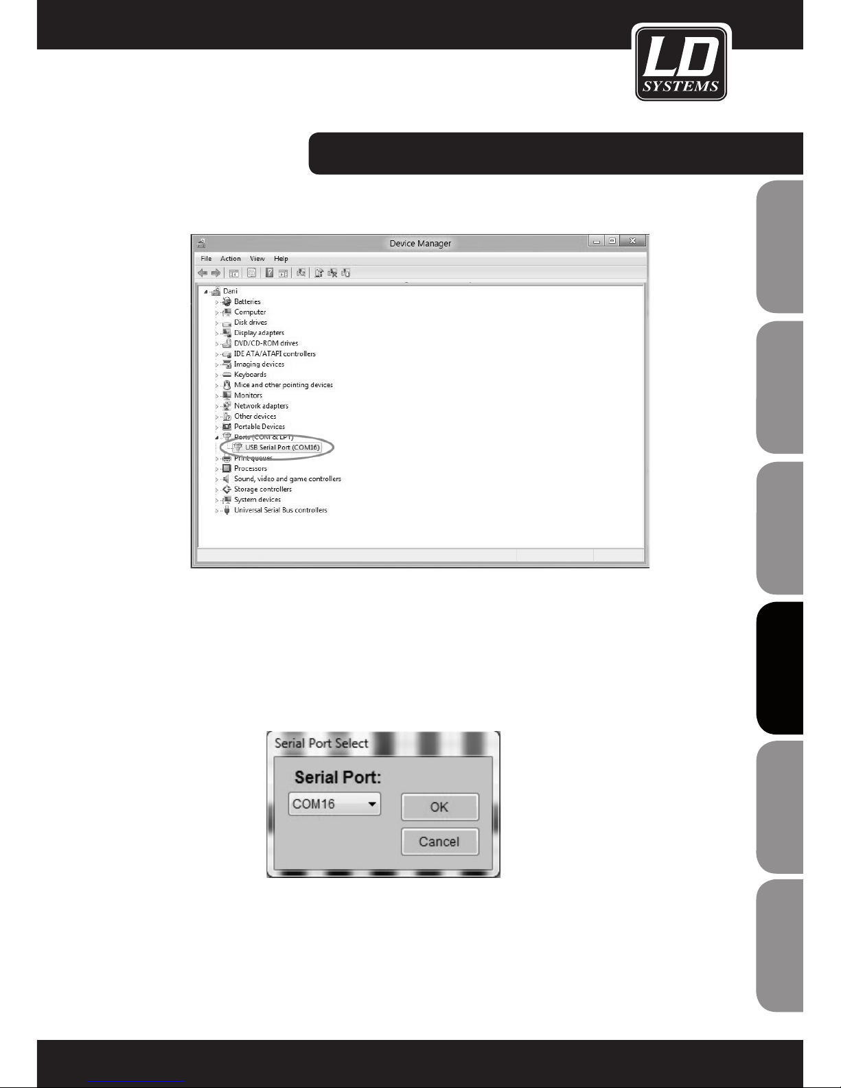
ITALIANOPOLSKIESPAÑOL
FRANCAISFRANCAIS FRANCAISFRANCAIS
FRANCAISDEUTSCHENGLISH
95
En el Administrador de dispositivos se mostrará el número del puerto COM de "USB Serial Port".
Nota: El número del puerto COM de "USB Serial Port" estará comprendido entre 1 y 16.
Ahora conecte el WIN42 CONTROLLER HUB al conversor de USB a RS-485 mediante el cable RJ45 suministrado y luego abra el
software WIN42 CONTROL CENTER. En el menú "Tools" seleccione la opción "Communication", para ver si el número de puerto
del "USB Serial Port" coincide con el del programa WIN42 CONTROL CENTER (en nuestro ejemplo, COM16).
INSTALACIÓN DEL CONTROLADOR:
Page 96
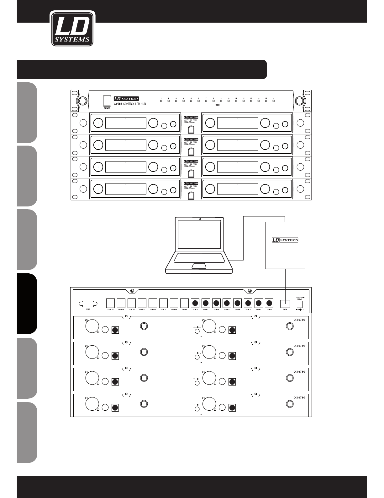
ENGLISHDEUTSCHFRANCAIS
FRANCAISFRANCAIS FRANCAISFRANCAIS
ESpAñoLpoLSKIITALIANo
96
CONEXIÓN DEL WIN42 CONTROLLER HUB:
Nota: El cable (16 suministrados) para conectar el WIN42 CONTROLLER HUB con los receptores WIN42 tiene dos conectores de
tamaño diferente. Conecte el conector grande al puerto COM (1 a 16) del WIN42 CONTROLLER HUB, y el conector pequeño al
puerto de salida de datos (DATA OUTPUT) del receptor WIN42.
CHANNEL2
XLR BALANCED
UNBAL
OUTPUT
Data Output
ANTENNA-AANTENNA-B
CHANNEL1
XLR BALANCED
D.C 12-18V
1000mA
UNBAL
OUTPUT
Data Output
CHANNEL2
XLR BALANCED
UNBAL
OUTPUT
Data Output
ANTENNA-AANTENNA-B
CHANNEL1
XLR BALANCED
D.C 12-18V
1000mA
UNBAL
OUTPUT
Data Output
CHANNEL2
XLR BALANCED
UNBAL
OUTPUT
Data Output
ANTENNA-AANTENNA-B
CHANNEL1
XLR BALANCED
D.C 12-18V
1000mA
UNBAL
OUTPUT
Data Output
CHANNEL2
XLR BALANCED
UNBAL
OUTPUT
Data Output
ANTENNA-AANTENNA-B
CHANNEL1
XLR BALANCED
D.C 12-18V
1000mA
UNBAL
OUTPUT
Data Output
1
1
3
5
7
2
4
682345678
USB RS485
DATA CONVERTER
DATA
USB
Page 97
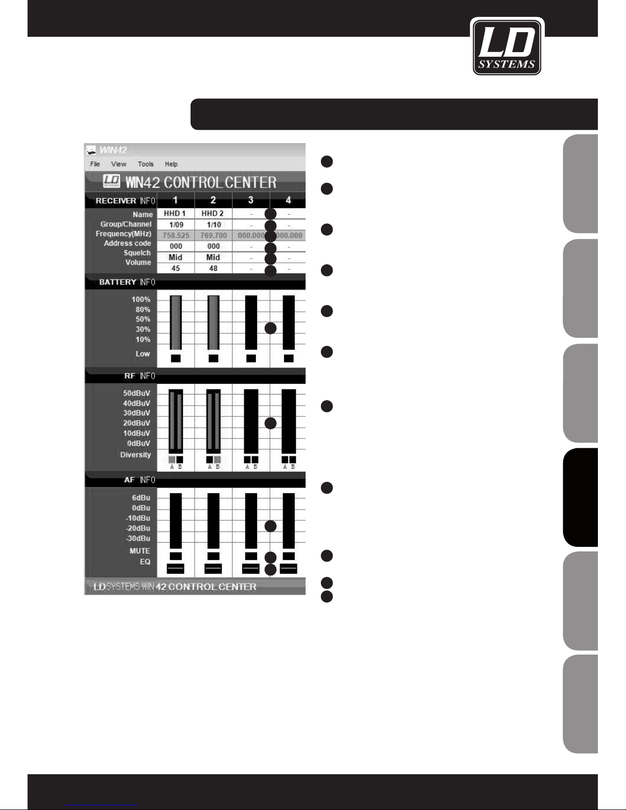
ITALIANOPOLSKIESPAÑOL
FRANCAISFRANCAIS FRANCAISFRANCAIS
FRANCAISDEUTSCHENGLISH
97
RECEIVER INFO (INFORMACIÓN DEL RECEPTOR)
1
NAME
Permite asignar un nombre al receptor.
2
GROUP/CHANNEL
Permite asignar el grupo de frecuencias y el
canal.
3
FREQUENCY
Muestra la frecuencia del grupo/canal
seleccionado arriba.
4
ADDRESS CODE
Permite asignar una dirección al receptor (0 a
224).
5
SQUELCH
Permite ajustar el silenciamiento (squelch) del
receptor (Low/Mid/High).
6
AJUSTE DEL VOLUMEN DEL RECEPTOR
(03 a 48)
BATTERY INFO (INFORMACIÓN DE BATERÍA)
7
INDICADOR DE ESTADO DE LA BATERÍA (0 A
100%)
Si el estado de batería del transmisor se acerca al
estado crítico, el indicador "LOW" se iluminará.
RF INFO (INFORMACIÓN DE RF)
8
INDICADOR DEL NIVEL DE RF DEL RECEPTOR
En la pantalla se indica el receptor activo de un
sistema diversity (A o B).
AF INFO (INFORMACIÓN DE AUDIO)
9
INDICADOR DE NIVEL DE SEÑAL DEL
RECEPTOR
10
ESTADO DE FUNCIÓN SILENCIO DEL RECEPTOR
11
EQ
Permite ajustar el ecualizador del receptor (plano/
pasoaltos/pasoaltos+refuerzo de agudos/refuerzo
de agudos).
EL SOFTWARE WIN42 CONTROL CENTER:
1
2
3
4
5
6
7
8
9
10
11
Page 98
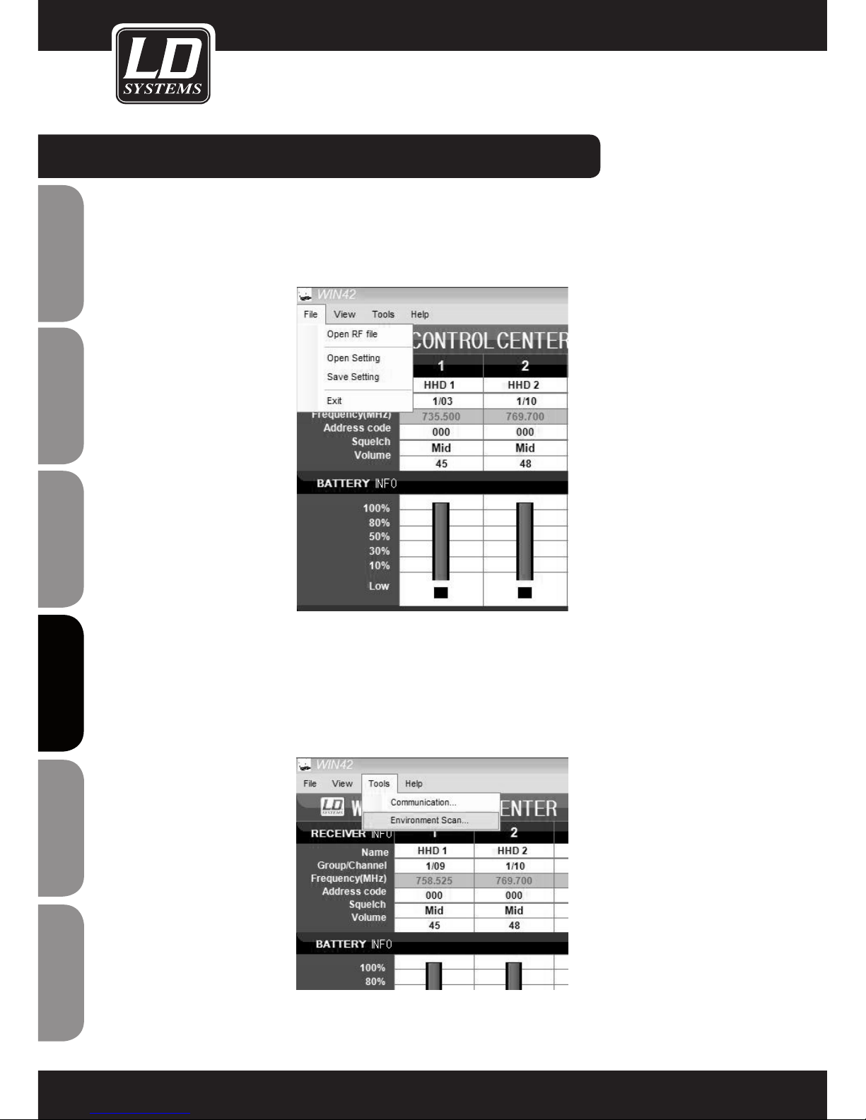
ENGLISHDEUTSCHFRANCAIS
FRANCAISFRANCAIS FRANCAISFRANCAIS
ESpAñoLpoLSKIITALIANo
98
GUARDAR Y ACTIVAR UNA CONFIGURACIÓN
Puede guardar en el ordenador todos los ajustes realizados en la pantalla principal para activarlos de nuevo más
adelante.
En la pantalla principal seleccione la opción Open Setting o Save Setting en el menú File.
ENVIRONMENT SCAN (BARRIDO DE BÚSQUEDA DE FRECUENCIAS LIBRES)
La función Environment Scan permite hacer un barrido completo de frecuencias del sistema WIN42 de LD
Systems para encontrar fácilmente las frecuencias libres.
Siga estas instrucciones para aprovechar toda la funcionalidad del software.
En el menú Tools seleccione la opción Environment Scan.
EL SOFTWARE WIN42 CONTROL CENTER:
Page 99
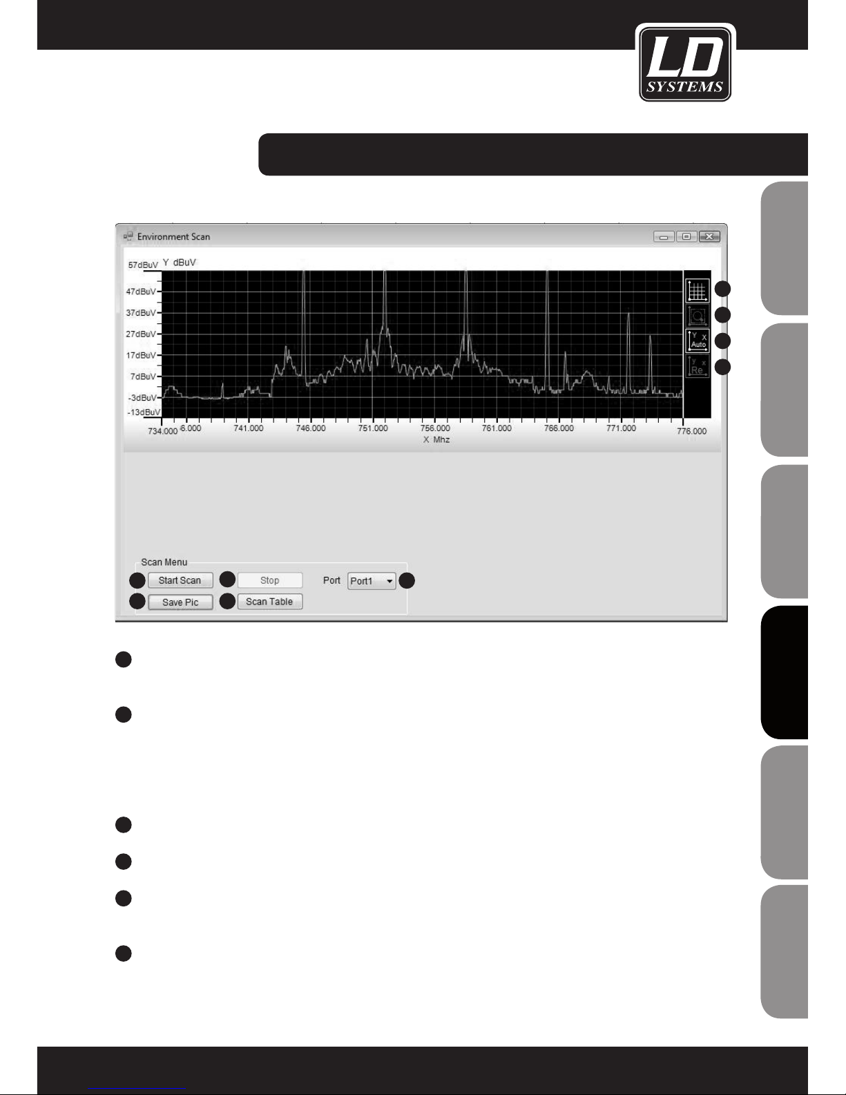
ITALIANOPOLSKIESPAÑOL
FRANCAISFRANCAIS FRANCAISFRANCAIS
FRANCAISDEUTSCHENGLISH
99
La ventana Environment Scan incluye las siguientes funciones (véase figura de ejemplo):
1
6
7
8
9
3
5
2
4
SCAN MENU (MENÚ BARRIDO)
1
PORT (PUERTO)
Seleccione el puerto de uno de los receptores conectados en el que realizar el barrido. Nota: Durante el
barrido, no podrá realizarse ninguna otra función en este receptor.
2
START SCAN (INICIAR BARRIDO)
Inicia el barrido de frecuencias. Se utiliza el puerto definido para hacer un barrido de frecuencias en el
receptor correspondiente. El nivel de la señal recibida se mostrará en una gráfica. El proceso completo
puede tardar varios minutos.
Si el barrido no se puede iniciar, aparecerá el mensaje "Scan Timeout". En este caso, compruebe el puerto
seleccionado (1) y que el receptor está correctamente conectado.
3
STOP (DETENER BARRIDO)
Detiene el barrido de frecuencias.
4
SAVE PIC (GUARDAR GRÁFICA)
Permite guardar el resultado del barrido como una imagen (en formato JPG) en el ordenador.
5
SCAN TABLE (TABLA DEL BARRIDO)
Permite ver en forma de tabla los resultados del barrido y la asignación de frecuencias libres a los receptores
conectados. Consulte también la sección "Scan Table“ más adelante.
6
MOSTRAR CUADRÍCULA
Muestra u oculta la cuadrícula de la gráfica.
EL SOFTWARE WIN42 CONTROL CENTER:
Page 100
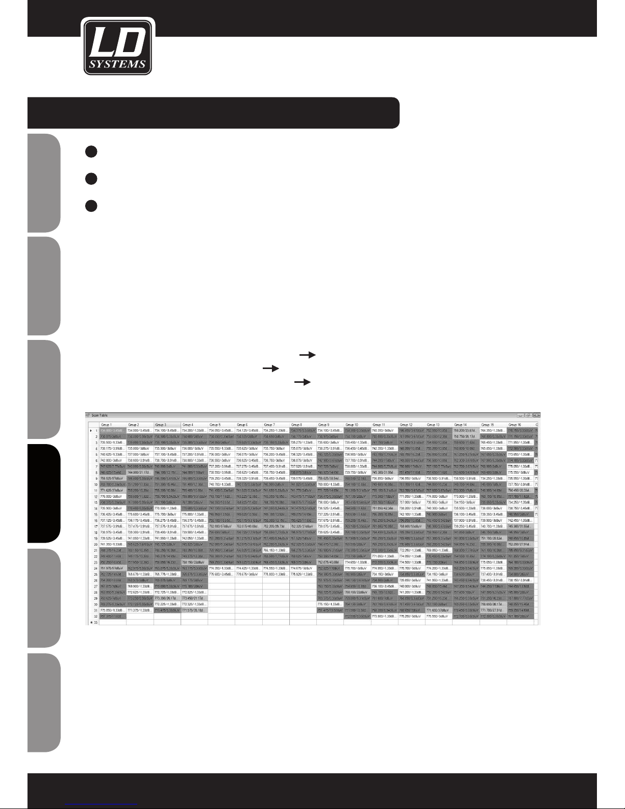
ENGLISHDEUTSCHFRANCAIS
FRANCAISFRANCAIS FRANCAISFRANCAIS
ESpAñoLpoLSKIITALIANo
100
7
ZOOM
Permite ampliar una zona de la gráfica. Seleccione con el ratón la zona que desea ampliar.
8
COORDENADAS AUTOMÁTICAS
Permite activar o desactivar el ajuste automático del eje de coordenadas.
9
COORDENADAS POR DEFECTO
Permite deshacer el zoom y volver a mostrar la gráfica a tamaño completo.
SCAN TABLE (TABLA DEL BARRIDO)
(véase figura de tabla de barrido de ejemplo)
Con esta función, podrá encontrar las frecuencias libres y asignarlas a los receptores conectados.
Realice el barrido como se describe en la sección Environment Scan y pulse el botón "Scan Table" para ver el
resultado del barrido en forma de tabla. En la tabla están todos los grupos con sus frecuencias correspondientes.
En los resultados del barrido se muestra, para cada frecuencia, el nivel de RF recibido. Además, las frecuencias
disponibles en los grupos aparecen resaltadas en colores diferentes.
Blanco: nivel de recepción menor o igual que 0 dBuV frecuencia libre
Amarillo: nivel de recepción de 0 a 20 dBuV frecuencia posiblemente ocupada
Rojo: nivel de recepción mayor o igual que 20 dBuV frecuencia ocupada
Guarde la tabla de barrido haciendo clic en el botón "Save" en la esquina inferior derecha de la pantalla para así
poder consultarla de nuevo en otro momento.
Para recuperar una tabla de barrido guardada, seleccione la opción "Open RF file" del menú "File" de la pantalla
principal.
EL SOFTWARE WIN42 Control Center:
 Loading...