

Page 1
*Bitte informieren Sie sich bei Ihrer lokalen Telekominikationsbehörde.
*Please inform your local Market Surveillance Authorities for Telecommunications.
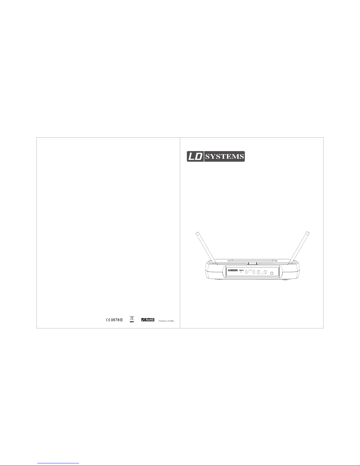
User Manual
ANTENNA
A
B
AUDIO
PEAK
NORM
POWER
VOLUME
MAX
MIN
LD ECO Sets - UHF Wireless Series
www.ld-systems.com
Page 2
UNBAL OUTPUT
UNBAL OUTPUT
MUTE LEVEL
MUTE LEVEL
AF OUTPUT
XLR BALANCED - 20dBV
AF OUTPUT
XLR BALANCED - 20dBV
D.C.12-18V I N
400mA
D.C.12-18V I N
400mA
++
ANTENNA
A
B
AUDIO
PEAK
NORM
POWER
VOLUME
MAX
MIN
1
112233445 6
2
1
2
3
4
5
6
1
2
3
4
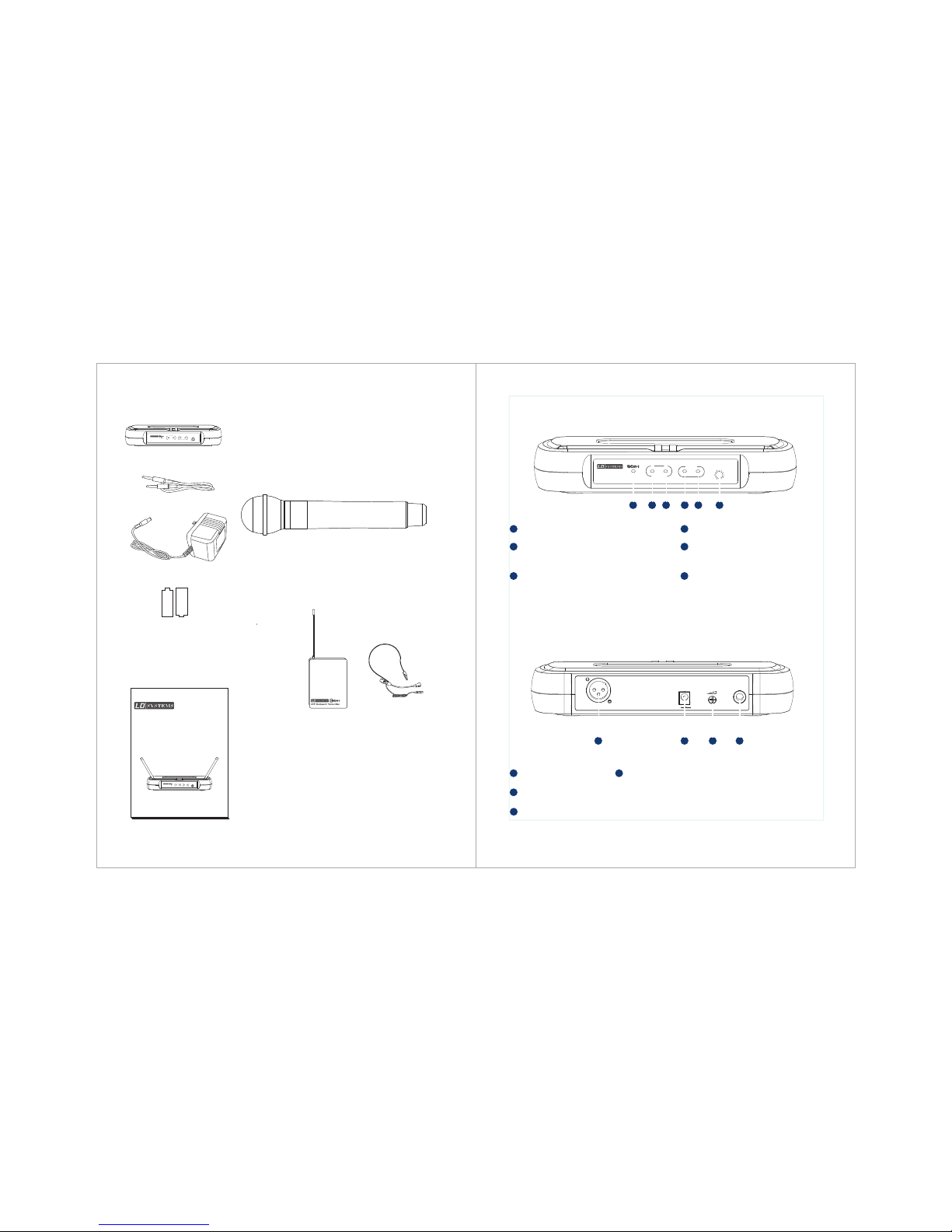
Voca list sy stem in clude s:
Free1 receiver
2 “AA” batteries
A 1/4” RF connector
Power supply
User guide
ECO Handheld Transmitter
ECO bodypack transmitter
Headset Microphone (MH1)
Hea dset sy stem in clude s:
System Compon ent s
All s ystem s inclu de:
Eco Receiver Fe atu res
Fro nt Pane l
Rea r Panel
This is the mute enabling threshold value, which is set to factory
default and there is usually no need to adjust it, if there are any
interference signals, this threshold value can be increased
by turning the knob clockwise until RF signal lamp goes out.
Fin e adjus tment o f mute th resho ld leve l
Unb alanc ed Outp ut
AC ad apter j ack
XLR o utput j ack
Aud io outp ut leve l contr ol
Lef t turn fo r outpu t level d ecrea se, rig ht
tur n for out put lev el incr ease.
Pow er indi cator Aud io leve l indic ator
Aud io leve l peak in dicat or
Cha nnel A ante nna LED l amp
Whe n it is ste adily l it, Cha nnel A ante nna is
wor king
Cha nnel B an tenna L ED lamp
Whe n it is ste adily l it, Cha nnel B an tenna i s
wor king
ANTENNA
A
B
AUDIO
PEAK
NORM
POWER
VOLUME
MAX
MIN
-
+
-
+
Bedien ungsa nleit ung
ANTENNA
A
B
AUDIO
PEAK
NORM
POWER
VOLUME
MAX
MIN
LD ECO Sets - UHF Wirel ess Series
Page 3
3
4
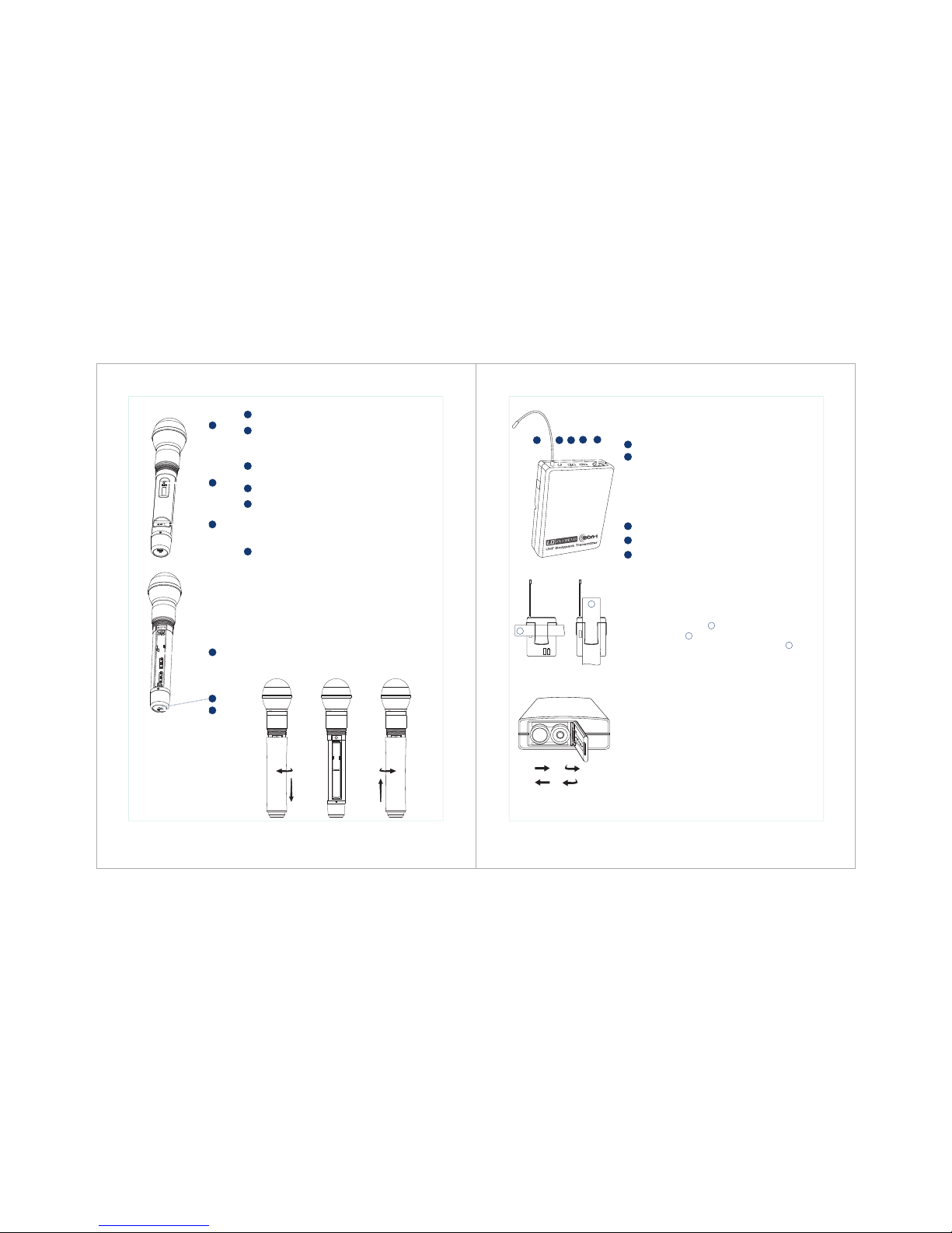
Fun ction s:
Han dheld Tr ansmi tter:
5
5
6
6
1
2
3
4
1
2
3
4
Exp ected l ife for t wo alka line ba tteri es is up to 1 0 hours .
Whe n turne d on, the B atter y indic ator fl ashes r ed and go es
off ag ain. If t he batt ery ind icato r const antly l ights u p red , the
bat terie s shoul d be chan ged imm ediat ely (as s hown be low).
Cha nging B atter ies:
Mic ropho ne head
A mdju st inpu t sensi tivit y of the icr ophon e head
On- off/mu te swit ch
Pow er/AS C/Bat tery lo w indic ator li ght.
Gre en on: po wer on
Gre en flas h: IR tra nsmis sion in p roces s.
Red f lash: b atter y low
Lef t turn fo r l dec rease , right t urn for
inc rease .
sen sitiv ity sen sitiv ity
Bat tery co mpart ment
H for h igh pow er and L for l ow powe r
RF po wer swi tch
Ant enna
On/ Off swit ch,wh en it in mi ddle po sitio n,mut e.
Two ga in sett ings ar e avail able on F ree1 Bo dypac k
cho ose the a pprop riate s ettin g for you r instr ument
Mic : micro phone
0: Gu itar wi th pass ive pic kups
-10 dB: Gui tar wit h activ e picku ps
1 2
3
4
1
2
3
4
5
- -
+ +
++
--
1
2
5
Gai n adjus tment s witch a nd mute i ndica tor
3-pin Mi crophone Inp ut Jack
Wea rin g the B ackp ack Tran smitt er:
Cha nging b atter ies:
Expected life for Two Alkaline batteries is approximately 8 hours.
When the transmitter light glows red, the batteries should be
changed immediately, as shown on the left.
Ope n
Clo se
Cli p the tra nsmit ter to be lt , or sli de a guit ar stra p throu gh
the t ransm itter c lip ,as s hown.
For b est res ults, s lide th e trans mitte r until t he belt i s
pre ssed ag ainst t he base f or the cl ip.
1
1
2
Fre e1 Body pack Tra nsmit ter
Featu res:
Power/ Low indicato r light
When tur ned on, the Batt ery indicato r flashes red an d goes
off again . If the battery i ndicator con stantly ligh ts up red , the
batter ies should be ch anged immedi ately
Page 4
5
6
Mainta in a line of sight b etween trans mitter and ant enna.
Avoid pla cing the recei ver near metal s urfaces or any d igital equip ment (CD playe rs, computes , etc)
Keep the r eceiver away f rom the wall and o ver 1m to the grou nd
Cellul ar telephone s and two-way ra dio and so on can in terfering th e transmitti ng frequenci es,
mainta in a distance fr om the interfe ring equipme nts or any cause i nterfering .
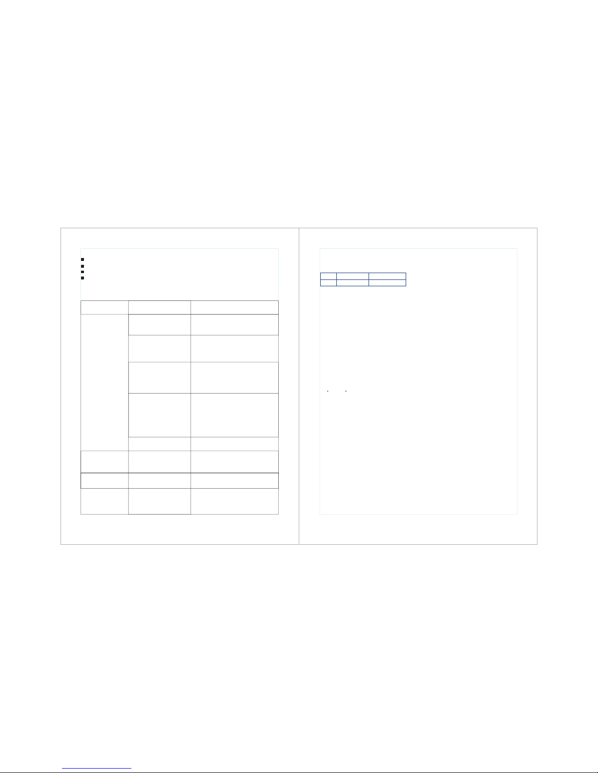
Trip s for imp rovin g Syste m Perfo rmanc e
Trou bles Sh ootin g
Iss ue Indi cator S tatus
No so und or fa int
sou nd
Dis torti on or
unw anted n oise bu rsts
Dis torti on leve l
inc rease s gradu ally
Sou nd leve l differ ent
fro m cable d guita r or
mic ropho ne, or wh en
usi ng diffe rent gu itars
Sol ution
Turn o n trans mitte r
Mak e sure th e +/- ind icato r on batt ery
mat ch the tr ansmi tter te rmina ls
Mak e sure AC ad apter i s secur ely
plu gged in to elec trica l outle t and int o
DC in put con necto r on rear p anel of
rec eiver.
Turn t he rece iver up
Turn u p the Gai n adjus tment s witch i n
the t ransm itter
Che ck the po wer con necti on of the
rec eiver a nd ampl ifier o r mixer
Take the r eceiv er away f rom the m etal
obj ects
Che ck whet her the re is ham per bet ween
rec eiver a nd tran smitt er
Mov e the tra nsmit ter nea r the rec eiver
Che ck the re ceive r and tra nsmit ter
whe ther us e the sam e frequ ency
Cha nge the b atter ies in tr ansmi tter
Rem ove nea rby sou rces of R F inter fer ence( CD play ers, co mpute rs , digi tal
effe cts ,in -ear mo nitor s ystem s, etc. )
Adju st tran smitt er agai n and rec eiver
vol ume as ne cessa ry
Rec eiver R F indic ator gl ows
Rec eiver R F indic ator off ,
tra nsmit ter Nind icato r O
Tran smitt er ON Ind icato r
sto p flash ing
Pow er indi cator o ff
Tran smitt er low ba ttery
ind icato r ON
Rec eiver R F indic ator ON
Tran smitt er low ba ttery
ind icato r ON
Cha nge the b atter ies in tr ansmi tter
Spe cific ation s
Frequency Range and Transmitter Output level
Operating Range under Typical Condition
50m (150 ft.)
Note: actual range depends on RF signals
absorption,reflection, and interference.
Audio Frequency Response (+/-3 dB)
60Hz~16KHz
Total Harmonic Distortion
( +/- 30 KHz deviation,1 KHz tone)
<1%
Dynamic Range
>90 dB (A –weighted)
Operating Temperature Range
-10 C to +50 C
Note: battery characteristics may limit
the range
Audio Input Level Maximum
0 dBV ~+20 dBV
Gain adjustment Range
30 dB
Input Impedance
470 kilohm
85mm H × 65mm W × 23mm D
Weight
80 grams without batteries
Power Requirement
Two “AA” size alkaline or rechargeable batteries
Battery life
>8 hours (Alkaline)
Band Range Transmitter RF level
UE 838-865 MHz* 10dBm
Sys tem
Bod ypack Tr ansmi tter
Audio In put Level maxi mum
0 dBV
Dimens ions (includ ing the microp hone)
250mm × 53 mm Diameter
Weight
270 gram s
Batter y Requiremen ts
2 “AA” alkal ine batterie s or rechargea ble
batter ies Battery Li fe
>10 hours ( Alkaline)
Audio Ou tput Level Max imum (ref. +/- 30 KHz, 1 KHz)
XLR conn ector (into 60 0 load): - 12 dBV
1/4inc h connector (i nto 3000 l oad): -18 dBV
Output I mpedance
XLRcon nector 200oh m
1/4inc h connector 1k ilohm
XLR Outp ut
Impeda nce balanced
Pin 1: Gro und
Pin 2: (+)
Pin 3: (-)
Power Re quirements
12-18 Vd c at 400 mA , supplied b y external pow er supply
Ω
Ω
Sensit ivity (inter mediate freq uency adjust ment
audio no ise output <-9 2 dB)
Image Re jection
> 90 dB
Dimens ions
235mm H ×118mm W × 4 4mm D
Weight
370 gram s
* Availab le fixed frequ encies:
863.1 00 MHz | 863. 900 MHz | 864 .500 MHz
864.9 00 Mhz
---
793.1 50MHZ | 797 .050MHZ | 8 00.600M HZ
802.3 00MHZ | 813 .150MHZ
Rec eiver
Han dheld Tr ansmi tter
Page 5

8
7
(Applicable in the European Union and other European countries with separate
collection systems)
This marking shown on the product or its literature, indicates that it should not be
Disposed with other household wastes at the end of its working life. To prevent possible
harm to the environment or human health from uncontrolled waste disposal, please
Seperate this from other types of wastes and recycle it responsibly to promote the
sustainable reuse of material resources.
Household users should contact either the retailer where they purchased this product, or
their local government office, for details of where and how they can take this item for
environmentally safe recycling.
Business users should contact their supplier and check the terms and conditions of the
purchase contract. This product should not be mixed with other commercial wastes for
disposal.
(Waste Electrical & Electronic Equipment)
Correct Disposal of This Product
Recycling
(Batteries or rechargeable batteries)
The supplied batteries or rechargeable batteries can be recycled. Please dispose of them as special
waste or return them to your specialist dealer. In order to protect the environment, only dispose
exhausted batteries. Together for a good nature.
EG-Konformitätserklärung
Diese Geräte entsprechen den grundlegenden Anforderungen und den weiteren Vorgaben der Richtlinien 1999/5/EU, 89/336/EU und
73/23/EU.
CE Declaration of Conformity
This equipment is in compliance with the essential requirement and other relevant provisions of Directives 1999/5/EC, 89/336/ES or
73/23/EC.
Safety instructions
No user serviceable parts inside! Never open the transmitter, otherwise you can receive an
electric shock. If units are opened by customers in breach of this instruction, the warranty
Becomes null and void.
Use the transmitter in dry rooms only. Never expose it to water (eg: never place it in a
position where it could be subjected to water splashes). Do not place any objects containing
liquids on the top of the unit.
Keep the transmitter away from direct sunlight, central heating radiators, electric heaters and
similar sources of heat. Ensure sufficient ventilation, especially when it is mounted into a 19”
rack.
Use a damp cloth for cleaning the unit. Do not use any cleansing agents or solvents.
Attention! High Volume!
This is a professional transmission system. Commercial use is subject to the rules and
regulations of the trade association responsible. Adam Hall, as the manufacturer, is therefore
obliged to expressly point our possible health risks arising from use.
 Loading...