

Page 1
USER´S MANUAL
BEDIENUNGSANLEITUNG
MANUEL D`UTILISATION
MANUAL DE USUARIO
INSTRUKCJA OBSŁUGI
MANUALE D‘ USO
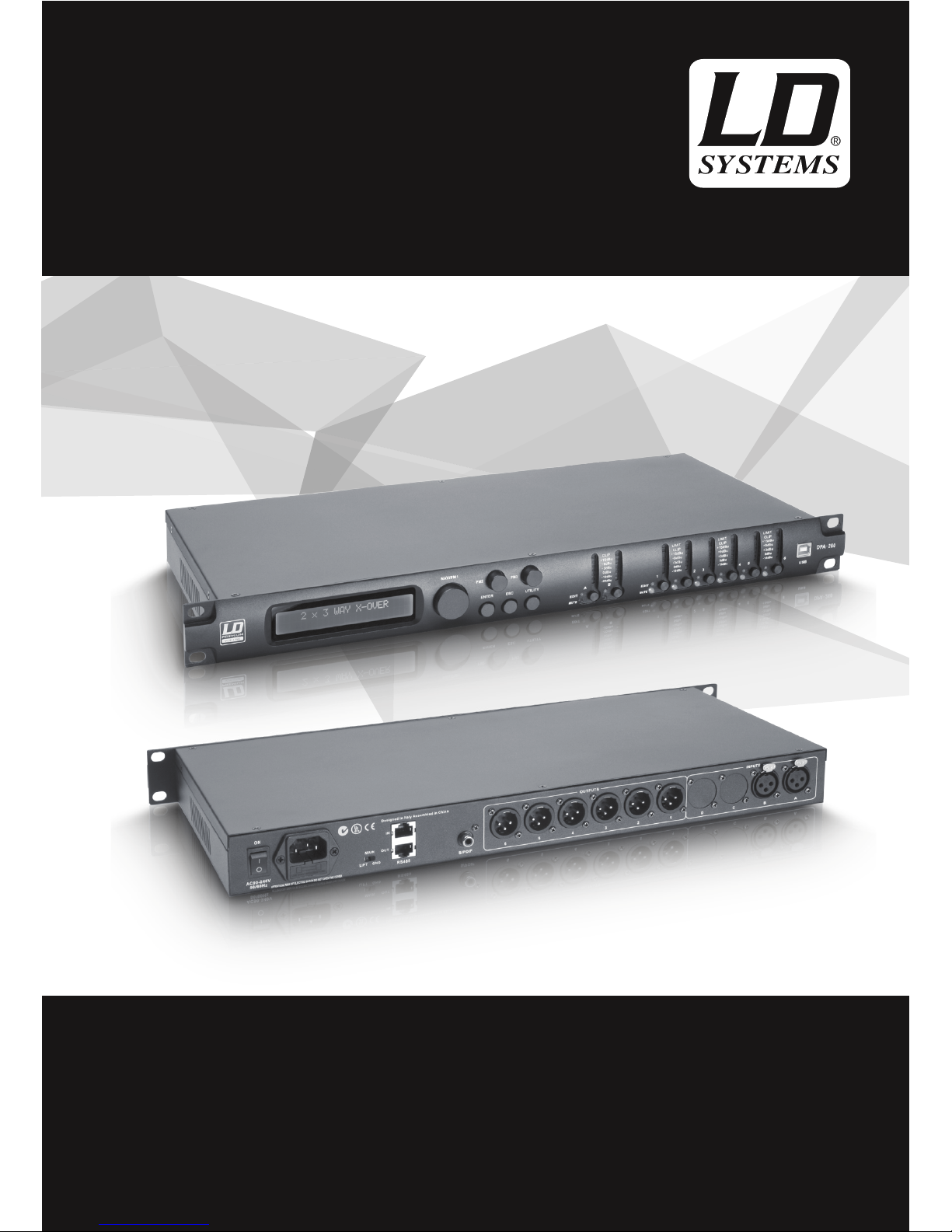
LDDPA260
19“ DSP CONTROLLER 2-IN-6
Page 2

CONTENTS / INHALTSVERZEICHNIS / CONTENU / CONTENIDO / TREŚĆ / CONTENUTO
ENGLISH
PREVENTIVE MEASURES 3-4
CONNECTIONS, CONTROLS, AND INDICATORS 5-6
MENU STRUCTURE UTILITY MENU 7
MENU STRUCTURE SYSTEM UTILITIES 7
MENU STRUCTURE PROGRAM, INTERFACE,
SECURITY UTILITIES 8
MENU STRUCTURE INPUTS A/B 9
MENU STRUCTURE OUTPUTS 1-6 9-10
LDDPA260 SOFTWARE (REPRESENTATION) 10
DPA260 SOFTWARE 11
SPECIFICATIONS 11-12
MANUFACTURER´S DECLARATIONS 12
DEUTSCH
SICHERHEITSHINWEISE 13-14
ANSCHLÜSSE, BEDIEN- UND ANZEIGEELEMENTE 15-16
MENÜSTRUKTUR UTILITY MENÜ 17
MENÜSTRUKTUR SYSTEM UTILITIES 17
MENÜSTRUKTUR PROGRAMM-, INTERFACE-,
SECURITY UTILITIES 18
MENÜSTRUKTUR INPUTS A/B 19
MENÜSTRUKTUR OUTPUTS 1-6 19-20
LDDPA260 SOFTWARE (BEISPIELDARSTELLUNG) 20
DPA260 SOFTWARE 21
SPEZIFIKATIONEN 21-22
HERSTELLERERKLÄRUNGEN 22
FRANCAIS
MESURES PRÉVENTIVES 23-24
CONNECTEURS, CONTRÔLES ET INDICATEURS 25-27
STRUCTURE DU MENU UTILITY 27
STRUCTURE DU MENU SYSTEM UTILITIES 27
STRUCTURE DU MENU PROGRAM UTILITIES,
INTERFACE UTILITIES, SECURITY UTILITIES 28
STRUCTURE DU MENU INPUTS A/B 29
MENÚ OUTPUTS 1-6 29-30
LOGICIEL LDDPA260 (COPIE D’ÉCRAN) 30
LOGICIEL DPA260 31
CARACTÉRISTIQUES 31-32
DECLARATIONS 32
ESPAÑOL
MEDIDAS DE SEGURIDAD 33-34
CONEXIONES, CONTROLES E INDICADORES 35-36
MENÚ UTILITY 37
MENÚ SYSTEM UTILITIES 37
MENÚ PROGRAM UTILITIES,
INTERFACE UTILITIES Y SECURITY UTILITIES 38
MENÚ INPUTS A/B 39
MENÚ OUTPUTS 1-6 39-40
SOFTWARE LDDPA260 (CAPTURA DE EJEMPLO) 40
SOFTWARE DPA260 41
ESPECIFICACIONES 41-42
DECLARACIÓN DEL FABRICANTE 42
POLSKI
ŚRODKI OSTROŻNOŚCI 43-44
PRZYŁĄCZA, ELEMENTY OBSŁUGI I WSKAŹNIKI 45-47
STRUKTURA MENU – MENU NARZĘDZI 47
STRUKTURA MENU – NARZĘDZIA SYSTEMU 47
STRUKTURA MENU – NARZĘDZIA PROGRAMOWE, NARZĘDZIA
INTERFEJSU, NARZĘDZIA ZABEZPIECZEŃ 48
STRUKTURA MENU – INPUTS A/B 49
STRUKTURA MENU OUTPUTS 1–6 49-50
PROGRAM LDDPA260 (PRZYKŁADOWY WIDOK) 50
PROGRAM DPA260 51
SPECYFIKACJE 51-52
DEKLARACJE PRODUCENTA 52
ITALIANO
MISURE PRECAUZIONALI 53-54
CONNESSIONI, COMANDI E INDICATORI 55-56
STRUTTURA DI MENU: UTILITY 57
STRUTTURA DI MENU: SYSTEM UTILITIES 57
STRUTTURA DI MENU: PROGRAMM UTILITIES,
INTERFACE UTILITIES, SECURITY UTILITIES 58
STRUTTURA DI MENU: INPUT A/B 59
STRUTTURA MENU: OUTPUT 1-6 59-60
SOFTWARE LDDPA260 (IMMAGINE DI ESEMPIO) 60
SOFTWARE DPA260 61
SPECIFICHE 61-62
DICHIARAZIONI DEL PRODUTTORE 62
Page 3
ITALIANOPOLSKIESPAÑOL
FRANCAISDEUTSCHENGLISH
3
ENGLISH
YOU‘VE MADE THE RIGHT CHOICE!
We have designed this product to operate reliably over many years. LD Systems stands for this with its name and many years of experience
as a manufacturer of high-quality audio products. Please read this User‘s Manual carefully, so that you can begin making optimum use of
your LD Systems product quickly.
You can find more information about LD-SYSTEMS at our Internet site WWW.LD-SYSTEMS.COM
PREVENTIVE MEASURES
1. Please read these instructions carefully.
2. Keep all information and instructions in a safe place.
3. Follow the instructions.
4. Observe all safety warnings. Never remove safety warnings or other information from the equipment.
5. Use the equipment only in the intended manner and for the intended purpose.
6. Use only sufficiently stable and compatible stands and/or mounts (for fixed installations). Make certain that wall mounts are properly
installed and secured. Make certain that the equipment is installed securely and cannot fall down.
7. During installation, observ e the applicable safety regulations for your country.
8. Never install and operate the equipment near radiators, heat registers, ovens or other sources of heat. Make certain that the equipment is
always installed so that is cooled sufficiently and cannot overheat.
9. Never place sources of ignition, e.g., burning candles, on the equipment.
10. Ventilation slits must not be blocked.
11. Do not use this equipment in the immediate vicinity of water (does not apply to special outdoor equipment - in this case, observe the
special instructions noted below. Do not expose this equipment to flammable materials, fluids or gases. Avoid direct sunlight!
12. Make certain that dripping or splashed water cannot enter the equipment. Do not place containers filled with liquids, such as vases or
drinking vessels, on the equipment.
13. Make certain that objects cannot fall into the device.
14. Use this equipment only with the accessories recommended and intended by the manufacturer.
15. Do not open or modify this equipment.
16. After connecting the equipment, check all cables in order to prevent damage or accidents, e.g., due to tripping hazards.
17. During transport, make certain that the equipment cannot fall down and possibly cause property damage and personal injuries.
18. If your equipment is no longer functioning properly, if fluids or objects have gotten inside the equipment or if it has been damaged in
anot her way, switch it off immediately and unplug it from the mains outlet (if it is a powered device). This equipment may only be repaired
by authorized, qualified personnel.
19. Clean the equipment using a dry cloth.
20. Comply with all applicable disposal laws in your country. During disposal of packaging, please separate plastic and paper/cardboard.
21. Plastic bags must be kept out of reach of children.
FOR EQUIPMENT THAT CONNECTS TO THE POWER MAINS
22. CAUTION: If the power cord of the device is equipped with an earthing contact, then it must be connected to an outlet with a protective
ground. Never deactivate the protective ground of a power cord.
23. If the equipment has been exposed to strong fluctuations in temperature (for example, after transport), do not switch it on immediately.
Moisture and condensation could damage the equipment. Do not switch on the equipment until it has reached room temperature.
24. Before connecting the equipment to the power outlet, first verify that the mains voltage and frequency match the values specified on the
equipment. If the equipment has a voltage selection switch, connect the equipment to the power outlet only if the equipment values and the
mains power values match. If the included power cord or power adapter does not fit in your wall outlet, contact your electrician.
25. Do not step on the power cord. Make certain that the power cable does not become kinked, especially at the mains outlet and/or power
adapter and the equipment connector.
26. When connecting the equipment, make certain that the power cord or power adapter is always freely accessible. Always disconnect the
equipment from the power supply if the equipment is not in use or if you want to clean the equipment. Always unplug the power cord and
power adapter from the power outlet at the plug or adapter and not by pulling on the cord. Never touch the power cord and power adapter
with wet hands.
27. Whenever possible, avoid switching the equipment on and off in quick succession because otherwise this can shorten the useful life of
the equipment.
28. IMPORTANT INFORMATION: Replace fuses only with fuses of the same type and rating. If a fuse blows repeatedly, please contact an
authorised service centre.
29. To disconnect the equipment from the power mains completely, unplug the power cord or power adapter from the power outlet.
30. If your device is equipped with a Volex power connector, the mating Volex equipment connector must be unlocked before it can be removed.
However, this also means that the equipment can slide and fall down if the power cable is pulled, which can lead to personal injuries and/or
other damage. For this reason, always be careful when laying cables.
31. Unplug the power cord and power adapter from the power outlet if there is a risk of a lightning strike or before extended periods of disuse.
Page 4
4
DEUTSCHFRANCAIS
ESPAÑOL
ENGLISH
ITALIANO POLSKI
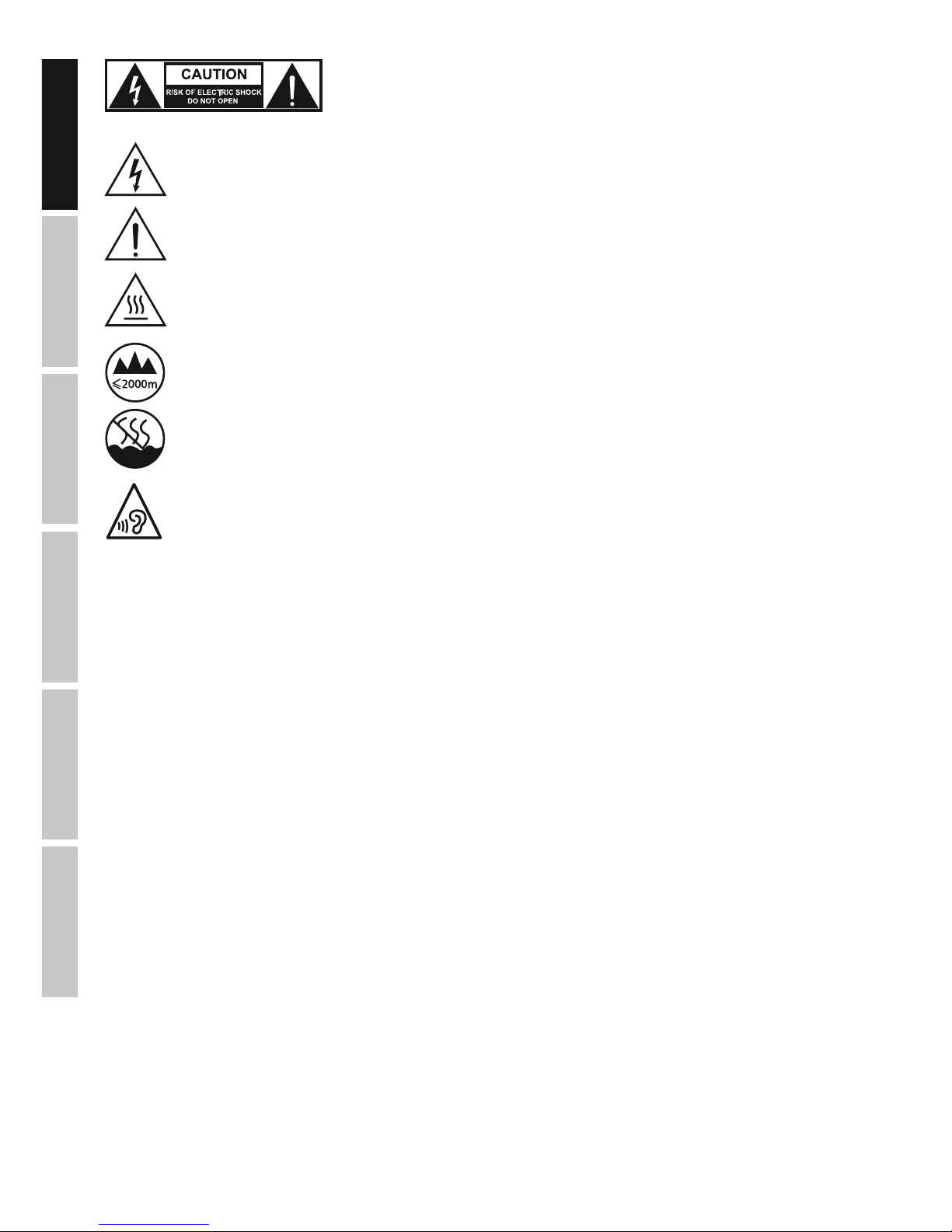
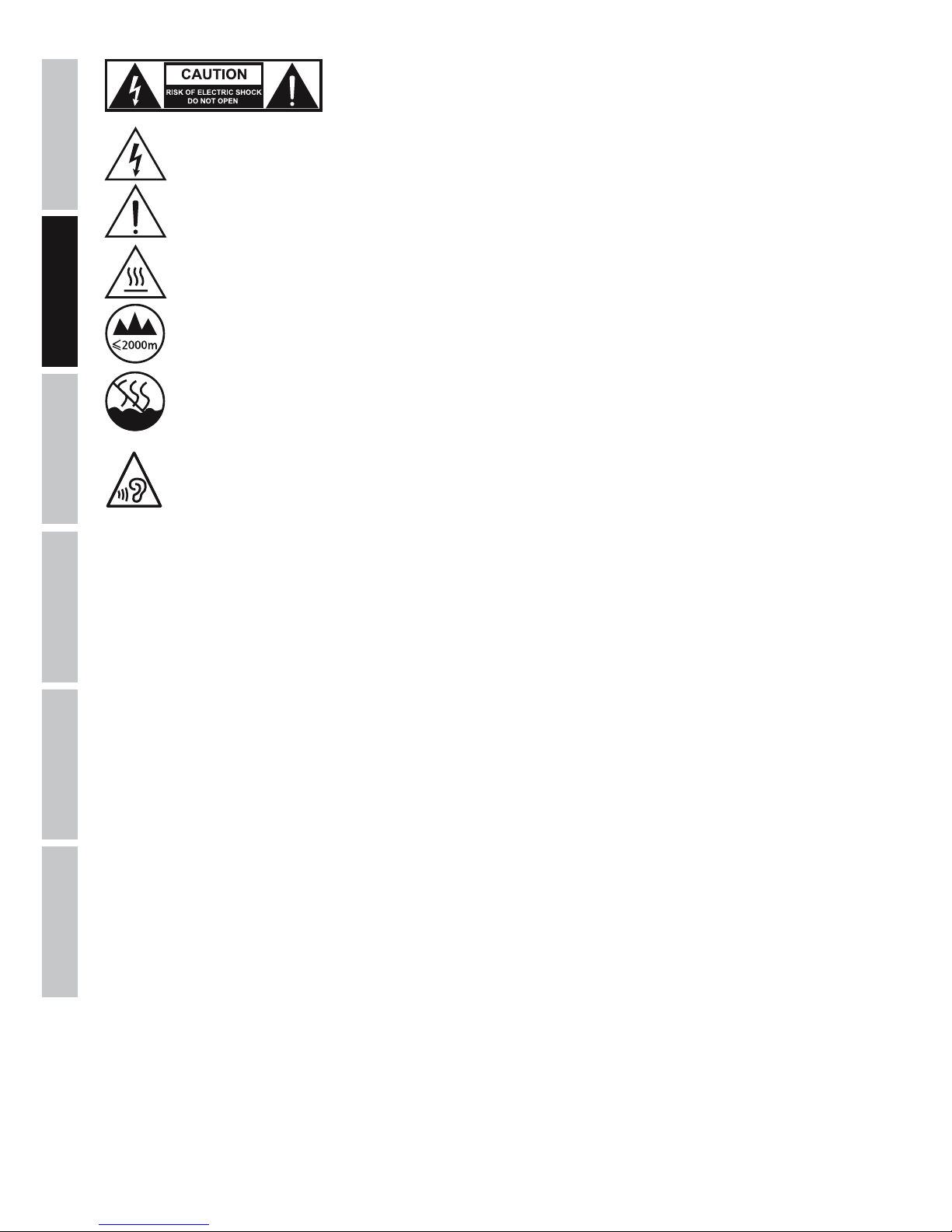
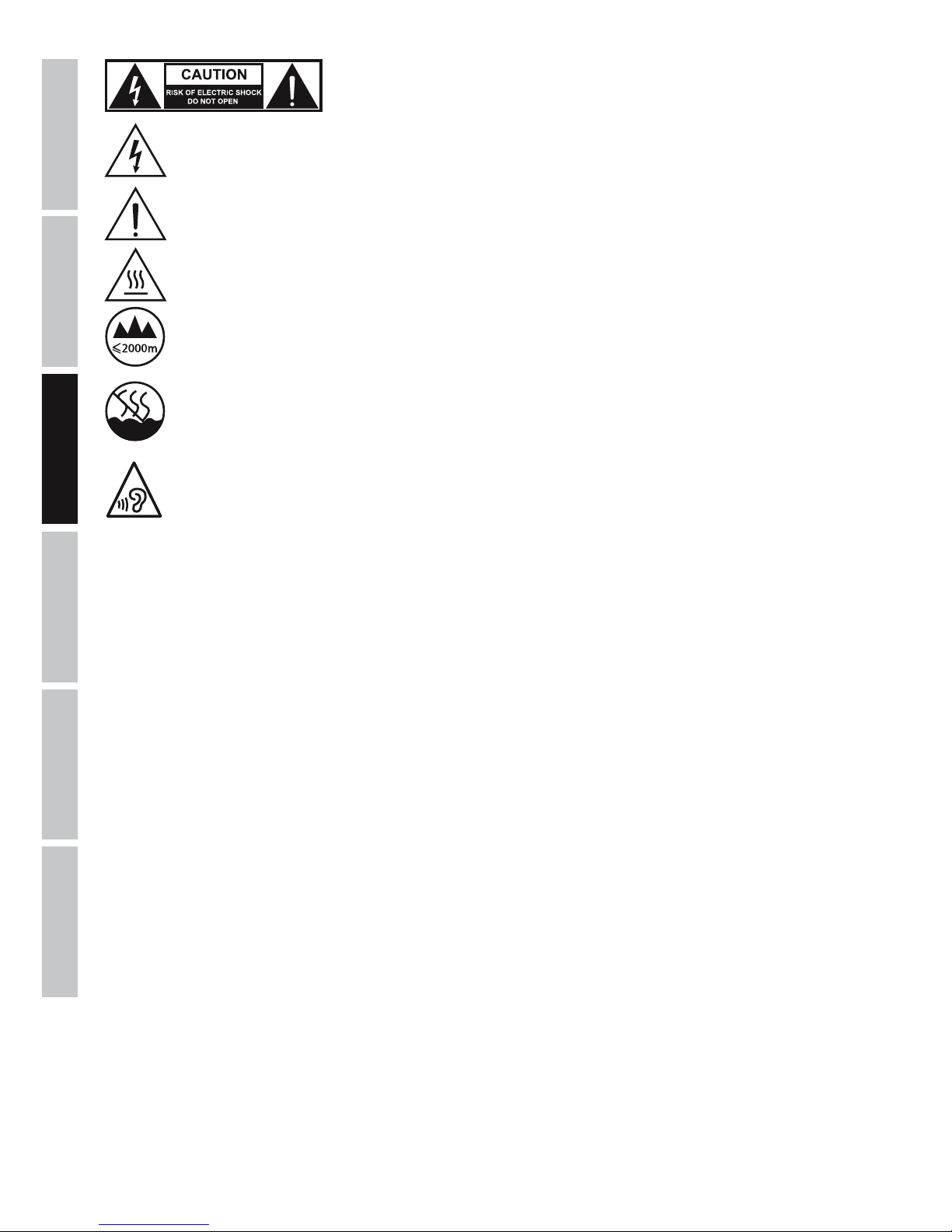
CAUTION:
To reduce the risk of electric shock, do not remove cover (or back). There are no user serviceable parts
inside. Maintenance and repairs should be exclusively carried out by qualified service personnel.
The warning triangle with lightning symbol indicates dangerous uninsulated voltage inside the unit, which may cause an
electrical shock.
The warning triangle with exclamation mark indicates important operating and maintenance instructions.
Warning! This symbol indicates a hot surface. Certain parts of the housing can become hot during operation. After use, wait for
a cool-down period of at least 10 minutes before handling or transporting the device.
Warning! This device is designed for use below 2000 metres in altitude.
Warning! This product is not intended for use in tropical climates.
To prevent possible hearing damage, avoid listening at high volume levels over long periods of time.
Even exposure to short bursts of loud noise can result in hearing loss. Please keep the volume constantly at a comfortable level.
CAUTION! HIGH VOLUMES IN AUDIO PRODUCTS!
This device is meant for professional use. Therefore, commercial use of this equipment is subject to the respectively applicable national
accident prevention rules and regulations. As a manufacturer, Adam Hall is obligated to notify you formally about the existence of potential
health risks.
Hearing damage due to high volume and prolonged exposure: When in use, this product is capable of producing high sound-pressure levels
(SPL) that can lead to irreversible hearing damage in performers, employees, and audience members. For this reason, avoid prolonged
exposure to volumes in excess of 90 dB.
NOTE: This equipment has been tested and found to comply with the limits for a Class B digital device, pursuant to Part 15 of the FCC
Rules. These limits are designed to provide reasonable protection against harmful interference in a residential installation. This equipment
generates, uses and can radiate radio frequency energy and, if not installed and used in accordance with the instructions, may cause
harmful interference to radio communications. However, there is no guarantee that interference will not occur in a particular installation. If
this equipment does cause harmful interference to radio or television reception, which can be determined by turning the equipment off and
on, the user is encouraged to try to correct the interference by one or more of the following measures:
- Reorient or relocate the receiving antenna.
- Increase the separation between the equipment and receiver.
- Connect the equipment into an outlet on a circuit different from that to which the receiver is connected.
- Consult the dealer or an experienced radio/TV technician for help.
Page 5
ITALIANOPOLSKIESPAÑOL
FRANCAISDEUTSCHENGLISH
5
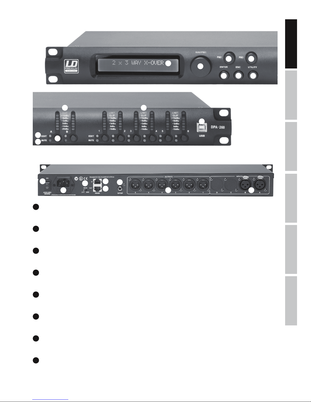
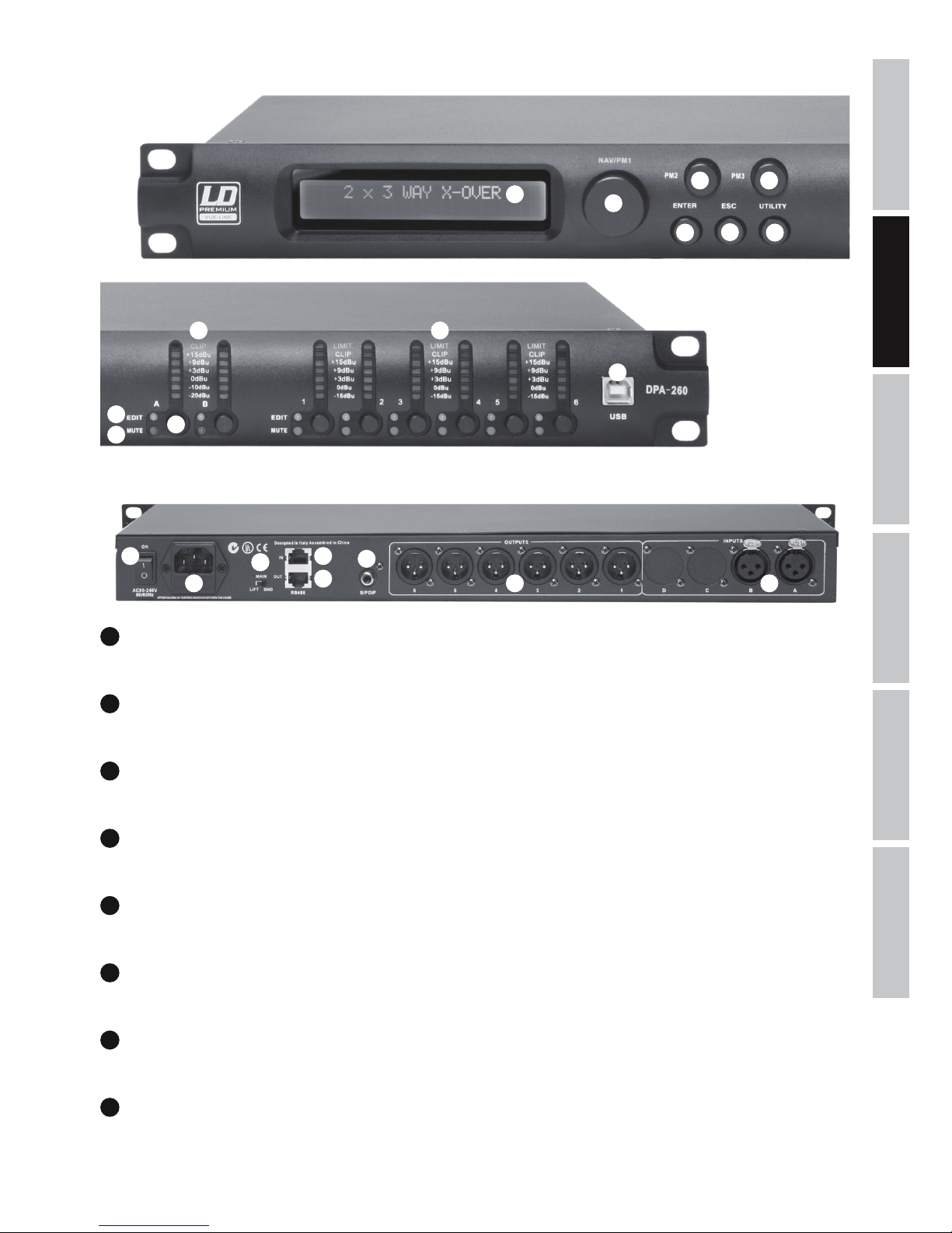
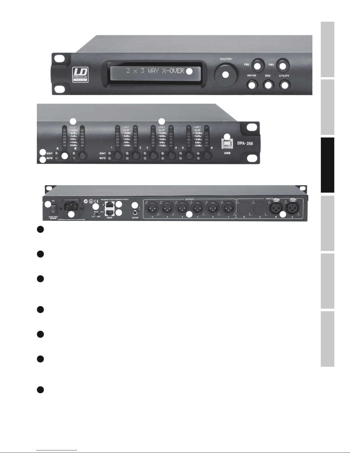
CONNECTIONS, CONTROLS, AND INDICATORS
1
2
3
4
5
6 7
9
12
13
14
15
16
17
18
19
20 21
8
10
11
1
DISPLAY
Multifunctional LC display with 2 x 24 characters.
2
UTILITY
To edit device settings in the menu, press the UTILITY button.
3
NAV/PM1
After pressing the UTILITY button, select between the menu items in the main menu and sub-menu, using the NAV/PM1 dial.
4
ENTER
To access a lower level in the menu structure and to confirm changes to any of the parameters, press ENTER.
5
ESC
Press the ESC button in the menu structure to access a higher level and return to the main display.
6
PM2
Use the PM2 dial to change parameters of a menu item. Confirm the input with ENTER.
7
PM3
Use the PM3 dial to change parameters of a menu item. Confirm the input with ENTER.
8
INPUT METER A / B
7-Segment LED level meter for the input channels A and B. As soon as the red CLIP LED lights up on the upper end of the level meter,
reduce the volume level of the playback device (e.g. mixer) to avoid distortion (maximum +20 dBu).
Page 6
6
DEUTSCHFRANCAIS
ESPAÑOL
ENGLISH
ITALIANO POLSKI
9
OUTPUT METER 1 - 6
7-Segment LED level meter for the output channels 1 to 6. To avoid distortion, reduce the volume level of the corresponding output channel
as soon as the red CLIP LED lights up. The yellow LIMIT LED lights up when the output signal of the corresponding channel is limited by the
integrated limiter (limiter settings according to the system components).
10
EDIT-LED
Press button 12 of the desired input or output channel briefly to enter the edit mode of the channel. The blue EDIT LED of the selected
channel lights up. In order to exit the edit mode of the respective channel, briefly press button 12 again. The blue EDIT LED is extinguished.
11
MUTE-LED
Press button 12 of the desired input or output channel for about 2 seconds to mute the channel. The red MUTE LED of the selected channel
lights up. In order to switch off the mute feature of the respective channel, press button 12 again, for about 2 seconds The audio signal is
played back again and the red MUTE LED is extinguished.
12
FEATURE SWITCH INPUT A / B AND OUTPUT 1 - 6
Press the switch to access the features described in paragraphs 10 and 11.
13
USB-PORT
The USB-port is used to comfortably edit and manage all functions or presets of the LDDPA260 DSP controller on a Windows PC. Software
and drivers for Windows operating systems are enclosed with the unit, but can also be downloaded from our website WWW.LD-SYSTEMS.
COM, as well as presets for a wide range of LD Systems speakers.
14
ON
On / Off switch for the power supply of the device.
15
IEC POWER SOCKET WITH INTEGRAL FUSE HOLDER
Used to power the device. An appropriate power cord is included in the delivery. IMPORTANT INFORMATION: Replace the fuse only with a
fuse of the same type and rating (T800mAL/250V)! If the fuse blows repeatedly, please contact an authorised service centre.
16
GROUND LIFT
Can eliminate ground loop hum if devices with varying ground potentials are connected.
17
RS485 IN
In conjunction with the USB to RS485 adapter LDDPA260RC, this interface enables the remote control of the LDDPA260 via a conventional
XLR-multi-core through a Windows-based computer on the mixer
18
RS485 OUT
Is used to route the control signal to one or more additional LDDPA260 DSP controllers.
19
S/PDIF
Digital stereo input in coaxial S/PDIF format.
20
OUTPUTS 1 - 6
Balanced audio inputs with 3-pin male XLR sockets.
21
INPUTS A + B
Balanced audio inputs with 3-pin female XLR sockets.
Page 7
ITALIANOPOLSKIESPAÑOL
FRANCAISDEUTSCHENGLISH
7
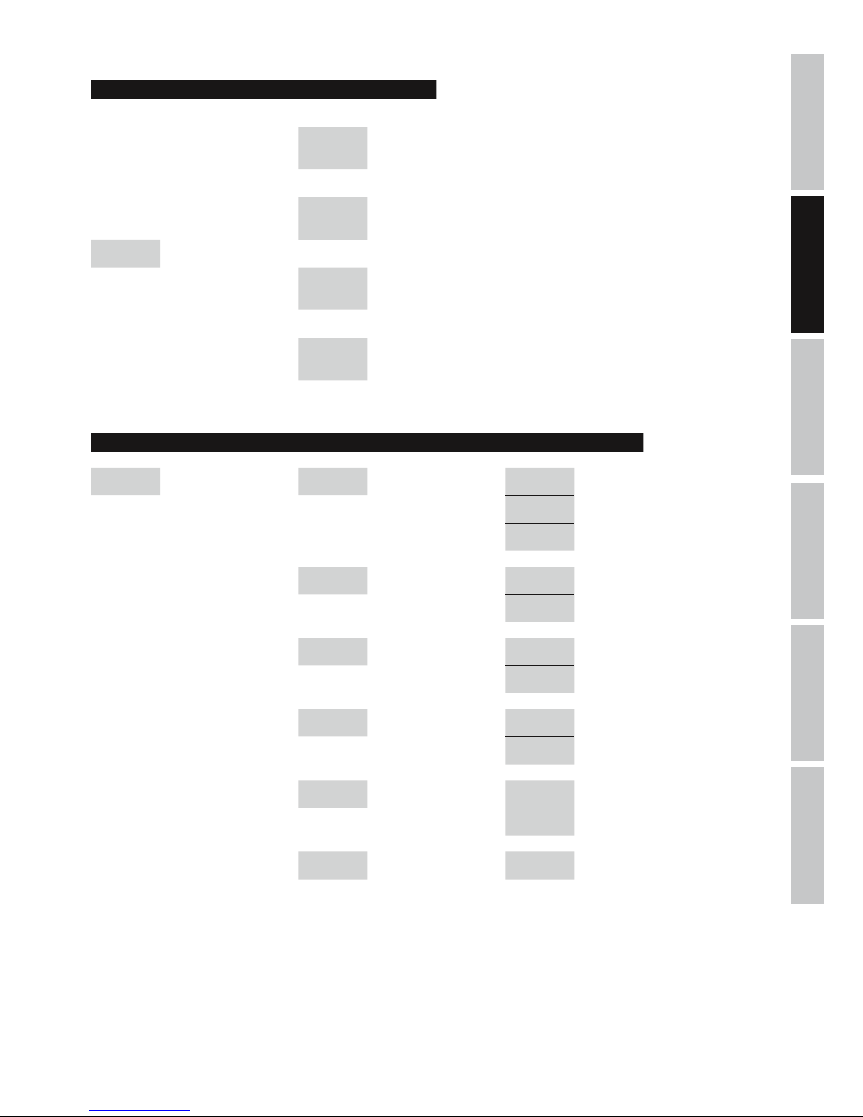
MENU STRUCTURE UTILITY MENU
Display: Display:
System Utilities
-> ENTER ->
<- ESC
Program Utilities
-> ENTER ->
<- ESC
Main Menu UTILITY NAV/PM1
Interface
Utilities
-> ENTER ->
<- ESC
Security Utilities
-> ENTER ->
<- ESC
MENU STRUCTURE SYSTEM UTILITIES
Display: Display: Display:
System Utilities
-> ENTER ->
<- ESC
NAV/PM1 System Setup
-> ENTER ->
<- ESC
PM2/3 2x2 WAY + SUB -> ENTER <-
2x3 WAY XOVER -> ENTER <-
6 WAY XOVER -> ENTER <-
Input Routing
-> ENTER ->
<- ESC
PM2/3 Source : Analog -> ENTER <-
Source : Digital -> ENTER <-
Power-On
Procedure
-> ENTER ->
<- ESC
PM2/3 Fade-In : On -> ENTER <-
Fade-In : Off -> ENTER <-
Delay Units
-> ENTER ->
<- ESC
PM2/3
Unit : Distan-
ce(m)
-> ENTER <-
Unit : Time(ms) -> ENTER <-
Ramps on
changes
-> ENTER ->
<- ESC
PM2/3 Ramps : On -> ENTER <-
Ramps : Off -> ENTER <-
Software
Version
-> ENTER ->
<- ESC
Version : V1.xx <- ESC
Page 8
8
DEUTSCHFRANCAIS
ESPAÑOL
ENGLISH
ITALIANO POLSKI
Display: Display: Display: Display:
Program
Utilities
-> ENTER ->
<- ESC
NAV/PM1
Recall a
Program
-> ENTER ->
<- ESC
PM2/3 01 - 24
-> 2x ENTER <-
<- ESC
Save a
Program
-> ENTER ->
<- ESC
PM2/3 01 - 24
-> ENTER ->
<- ESC
Set Program
Name
NAV/PM1
PM2/3
-> 2x ENTER <-
<- ESC
Delete a
Program
-> ENTER ->
<- ESC
PM2/3 01 - 24
-> 2x ENTER <-
<- ESC
Display: Display: Display: Display: Display:
Interface
Utilities
-> ENTER ->
<- ESC
Interface
Setup
-> ENTER ->
<- ESC
PM2/3 Source : USB
-> ENTER
<- ESC
Source :
RS485
-> ENTER ->
<- ESC
NAV/PM1
Remote ID
Num = xx
PM2/3
Remote ID
Num = 01
- 32
-> ENTER
<- ESC
Display: Display: Display: Display: Display: Display:
Security
Utilities
-> ENTER ->
<- ESC
NAV/PM1
Show
Parameter
-> ENTER ->
<- ESC
PM2/3
Parameter
will be
shown
-> ENTER <-
Parameter
will not be
shown
-> ENTER <-
Lock Unit
-> ENTER ->
<- ESC
PM2/3 Lock : On
-> ENTER ->
<- ESC
Main Menu
(Menu
locked)
(to unlock)
UTILITY ->
Lock Unit -> ENTER -> PM2/3 Lock : Off -> ENTER <-
Lock : Off -> ENTER <-
User
Password
-> ENTER ->
<- ESC
NAV/PM1
PM2/3
User
Password
[000000]
-> ENTER ->
<- ESC
NAV/PM1
PM2/3
New
Password
[xxxxxx]
-> ENTER ->
<- ESC
NAV/PM1
PM2/3
Confirm
Password
[xxxxxx]
-> ENTER <-
Enable
Password
-> ENTER ->
<- ESC
PM2/3
Password :
Disable
-> ENTER
Password :
Enable
-> ENTER ->
Main Menu
(Menu
locked)
(to unlock)
UTILITY ->
User
Password
[xxxxxx]
-> ENTER <-
MENU STRUCTURE PROGRAM, INTERFACE, SECURITY UTILITIES
Page 9
ITALIANOPOLSKIESPAÑOL
FRANCAISDEUTSCHENGLISH
9
MENU STRUCTURE INPUTS A/B
Display: Display:
EDIT INPUT
A/B:
-> EDIT
A/B ->
NAV/PM1
Input-A/B
EQ1-EQ5
-> ENTER -> NAV/PM1 KHz <- ESC
PM2 BW <- ESC
PM3 dB <- ESC
Input-A/B
Gain
-> ENTER -> PM2/3 dB <- ESC
Input-A/B
Delay
-> ENTER -> PM2/3
m/ms
(0 m...288,65932 m / 0 ms...848,998 ms)
<- ESC
MENU STRUCTURE OUTPUTS 1-6
Display: Display:
EDIT OUTPUT
1-6:
-> EDIT
1-6 ->
NAV/PM1 Out 1-6 HPF -> ENTER -> PM2 KHz <- ESC
PM3 No Cut-Off <- ESC
Butwrth 6 dB <- ESC
Butwrth 12 dB <- ESC
Lnk/Ril 12 dB <- ESC
Bessel 12 dB <- ESC
Butwrth 18 dB <- ESC
Butwrth 24 dB <- ESC
Lnk/Ril 24 dB <- ESC
Bessel 24 dB <- ESC
Out 1-6 LPF -> ENTER -> PM2 KHz <- ESC
PM3 No Cut-Off <- ESC
Butwrth 6 dB <- ESC
Butwrth 12 dB <- ESC
Lnk/Ril 12 dB <- ESC
Bessel 12 dB <- ESC
Butwrth 18 dB <- ESC
Butwrth 24 dB <- ESC
Lnk/Ril 24 dB <- ESC
Bessel 24 dB <- ESC
Out 1-6 EQ1-EQ7 -> ENTER -> NAV/PM1 KHz <- ESC
PM2 BW <- ESC
PM3 dB <- ESC
Page 10
10
DEUTSCHFRANCAIS
ESPAÑOL
ENGLISH
ITALIANO POLSKI
Out 1-6 Vu-Meter -> ENTER -> PM2/3 Level <- ESC
Limiter Act <- ESC
Out 1-6 Name -> ENTER ->
NAV/PM1
PM2/3
Name = xxxxxx -> ENTER <-
Out 1-6 Source -> ENTER -> PM2/3 InA <- ESC
InB <- ESC
InA+InB <- ESC
Out 1-6 Gain -> ENTER -> PM2/3 dB <- ESC
Out 1-6 Limiter -> ENTER -> NAV/PM1 Attack ms <- ESC
PM2 Release s <- ESC
PM3 dBu <- ESC
Out 1-6 Delay -> ENTER -> PM2/3
m/ms
(0 m...288,65932 m /
0 ms...848,998 ms)
<- ESC
Out 1-6 Polarity -> ENTER -> PM2/3 Normal <- ESC
Invert <- ESC
Display: Display:
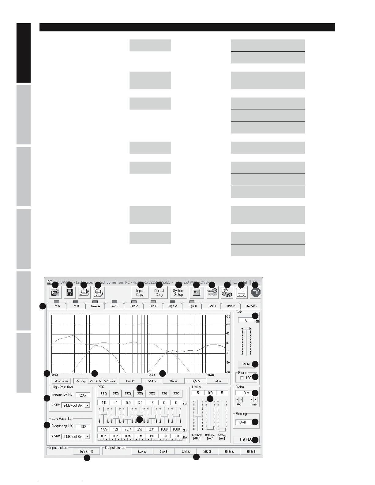
LDDPA260 SOFTWARE (REPRESENTATION)
1 2 3 4 5 6 7 109 11 12
13
1415 16
17
18
19
20
8
21
25
22
24
23
26
27
28
29
Page 11
ITALIANOPOLSKIESPAÑOL
FRANCAISDEUTSCHENGLISH
11
DPA260 SOFTWARE
NOTE: If a connection is established between DPA260 controller and PC/Software via USB or RS485, all the controls on the front panel of the
controller are locked.
1. Opening controller presets stored on a storage medium.
2. Backing up modified and newly created controller presets on a storage medium.
3. Transferring presets to the DPA260 controller. Up to 24 controller presets can be stored on a DPA260 unit.
4. Displaying controller presets from the DPA260.
5. Copying the settings of one input channel to another.
6. Copying the settings of one output channel to another.
7. Configuring the crossover function of the DPA260 controller (2 x 2-WAY XOVER + SUB, 2 x 3-WAY XOVER, 6 WAY XOVER)
8. Locking the output channels in the software. If the lock function is activated, it is possible to make changes in the input channels (software).
9. Locking the DPA260 controller (6-digit password). The lock on the controller remains active even after quitting the software and separating
the connection to the PC and can only be released with the help of the software or the unlock function of the DPA260 controller.
10. Renaming the DPA260 controller.
11. Renaming the input and output channels.
12. Separating the software connection from the DPA260 controller.
13. Displaying the individual input and output channels, gain and delay settings and the overview.
14. Graphical representation of the EQ settings of the selected channels.
15. Displaying the EQ cursor of the selected channel.
16. Determining whether or not only the equalizer settings of the output channels, or of the input and output channels are summed and
graphically displayed.
17. Setting the Gain and display adjustment of the selected channel.
18. Muting the selected channel.
19. Inverting the polarity of the selected channel.
20. Setting the Delay adjustment of select channel (0 ms, 0,02 ms...848,998 ms / 0 m, 0,0068 m...288,65932 m).
21. Setting the input source of the selected channel.
22. Setting the high-pass filter of the selected channel.
23. Setting the low-pass filter of the selected channel.
24. 7-band equalizer of the selected output channel (5-band EQ in the input channels).
25. Setting the equalizer characteristic.
26. Resetting the equalizer settings of the selected channel.
27. Setting the Limiter settings of the selected channel.
28. Button for linking both input channels.
29. Button for linking both output channels.
SPECIFICATIONS
Model Name: LDDPA260
Product Type: DSP controller
Type: digital
Version: 6-channel
AD/DA Converter: 24-bit
Sampling Frequency: 48 kHz
Frequency Response: 20 - 20,000 Hz
Filter Type: Butterworth, Bessel, Linkwitz-Riley
Filter Slew Rate: 6, 12, 18, 24 dB/octave
Delay (In- and output channels) 0 ms, 0,02 ms...848,998 ms / 0 m, 0,0068 m...288,65932 m
Dynamic Range: 111 dB (A weighted)
S/N ratio: >106 dB
THD: < 0.005%
Channel Crosstalk: 107 dB (+ 20 dBu @ 1 kHz)
Max. Input Level: +20 dBu (balanced)
Page 12
12
DEUTSCHFRANCAIS
ESPAÑOL
ENGLISH
ITALIANO POLSKI
MANUFACTURER´S DECLARATIONS
MANUFACTURER‘S WARRANTY & LIMITATIONS OF LIABILITY
You can find our current warranty conditions and limitations of liability at: http://www.adamhall.com/media/shop/downloads/documents/
manufacturersdeclarations.pdf. To request warranty service for a product, please contact Adam Hall GmbH, Daimler Straße 9,
61267 Neu Anspach / Email: [email protected] / +49 (0)6081 / 9419-0.
CORRECT DISPOSAL OF THIS PRODUCT
(valid in the European Union and other European countries with a differentiated waste collection system)
This symbol on the product, or on its documents indicates that the device may not be treated as household waste. This is to avoid
environmental damage or personal injury due to uncontrolled waste disposal. Please dispose of this product separately from other waste
and have it recycled to promote sustainable economic activity. Household users should contact either the retailer where they purchased
this product, or their local government office, for details on where and how they can recycle this item in an environmentally friendly manner.
Business users should contact their supplier and check the terms and conditions of the purchase contract. This product should not be mixed
with other commercial waste for disposal.
FCC STATEMENT
This device complies with Part 15 of the FCC Rules. Operation is subject to the following two conditions:
(1) This device may not cause harmful interference, and
(2) This device must accept any interference received, including interference that may cause undesired operation
CE Compliance
Adam Hall GmbH states that this product meets the following guidelines (where applicable):
R&TTE (1999/5/EC) or RED (2014/53/EU) from June 2017
Low voltage directive (2014/35/EU)
EMV directive (2014/30/EU)
RoHS (2011/65/EU)
The complete declaration of conformity can be found at www.adamhall.com.
Furthermore, you may also direct your enquiry to [email protected].
Max Output Level: +20 dBu (balanced)
Input Impedance: 27 kOhm
Output Impedance: 120 ohms
Controls: Nav/Par1, Par2, Par3, Enter, Escape, Utility
Edit Input 1 - 2, Edit Output 1 - 6
Indicators: Multifunction LC-display, 2 x Audio Level Meter input level (6 segments), 2 x input Clip, 2 x input
Edit LED, 2 x input Mute LED, 6 x Audio Level Meter output level (5 segments),
6 x Output Clip, 6 x Output Limit, 6 x Output Edit LED, 6 x Output Mute LED
Line Inputs: 3 (2 x analogue, 1 x stereo digital)
Line Input Connectors: XLR (balanced), S/PDIF (RCA)
Line Outputs: 6
Line Output Connectors: XLR (balanced)
Interfaces: USB, RS485 (In & Out)
Power Socket: IEC power socket
Operating Voltage: 90 V AC - 250 V AC
Power Consumption: 14 W
Fuse: T800 mAL/250 V
Dimensions (W x H x D): 482 x 44.5 x 225 mm
Page 13
ITALIANOPOLSKIESPAÑOL
FRANCAISDEUTSCHENGLISH
13
DEUTSCH
SIE HABEN DIE RICHTIGE WAHL GETROFFEN!
Dieses Gerät wurde unter hohen Qualitätsanforderungen entwickelt und gefertigt, um viele Jahre einen reibungslosen Betrieb zu gewährleisten.
Dafür steht LD Systems mit seinem Namen und der langjährigen Erfahrung als Hersteller hochwertiger Audioprodukte. Bitte lesen Sie diese
Bedienungsanleitung sorgfältig, damit Sie Ihr neues Produkt von LD Systems schnell optimal einsetzen können.
Mehr Informationen zu LD SYSTEMS finden Sie auf unserer Internetseite WWW.LD-SYSTEMS.COM
SICHERHEITSHINWEISE
1. Lesen Sie diese Anleitung bitte sorgfältig durch.
2. Bewahren Sie alle Informationen und Anleitungen an einem sicheren Ort auf.
3. Befolgen Sie die Anweisungen.
4. Beachten Sie alle Warnhinweise. Entfernen Sie keine Sicherheitshinweise oder andere Informationen vom Gerät.
5. Verwenden Sie das Gerät nur in der vorgesehenen Art und Weise.
6. Verwenden Sie ausschließlich stabile und passende Stative bzw. Befestigungen (bei Festinstallationen). Stellen Sie sicher, dass Wandhalterungen
ordnungsgemäß installiert und gesichert sind. Stellen Sie sicher, dass das Gerät sicher installiert ist und nicht herunterfallen kann.
7. Beachten Sie bei der Installation die für Ihr Land geltenden Sicherheitsvorschriften.
8. Installieren und betreiben Sie das Gerät nicht in der Nähe von Heizkörpern, Wärmespeichern, Öfen oder sonstigen Wärmequellen. Sorgen
Sie dafür, dass das Gerät immer so installiert ist, dass es ausreichend gekühlt wird und nicht überhitzen kann.
9. Platzieren Sie keine Zündquellen wie z.B. brennende Kerzen auf dem Gerät.
10. Lüftungsschlitze dürfen nicht blockiert werden.
11. Betreiben Sie das Gerät nicht in unmittelbarer Nähe von Wasser. Bringen Sie das Gerät nicht mit brennbaren Materialien, Flüssigkeiten
oder Gasen in Berührung. Direkte Sonneneinstrahlung vermeiden!
12. Sorgen Sie dafür, dass kein Tropf- oder Spritzwasser in das Gerät eindringen kann. Stellen Sie keine mit Flüssigkeit gefüllten Behältnisse
wie Vasen oder Trinkgefäße auf das Gerät.
13. Sorgen Sie dafür, dass keine Gegenstände in das Gerät fallen können.
14. Betreiben Sie das Gerät nur mit dem vom Hersteller empfohlenen und vorgesehenen Zubehör.
15. Öffnen Sie das Gerät nicht und verändern Sie es nicht.
16. Überprüfen Sie nach dem Anschluss des Geräts alle Kabelwege, um Schäden oder Unfälle, z. B. durch Stolperfallen zu vermeiden.
17. Achten Sie beim Transport darauf, dass das Gerät nicht herunterfallen und dabei möglicherweise Sach- und Personenschäden verursachen kann.
18. Wenn Ihr Gerät nicht mehr ordnungsgemäß funktioniert, Flüssigkeiten oder Gegenstände in das Geräteinnere gelangt sind, oder das
Gerät anderweitig beschädigt wurde, schalten Sie es sofort aus und trennen es von der Netzsteckdose (sofern es sich um ein aktives Gerät
handelt). Dieses Gerät darf nur von autorisiertem Fachpersonal repariert werden.
19. Verwenden Sie zur Reinigung des Geräts ein trockenes Tuch.
20. Beachten Sie alle in Ihrem Land geltenden Entsorgungsgesetze. Trennen Sie bei der Entsorgung der Verpackung bitte Kunststoff und
Papier bzw. Kartonagen voneinander.
21. Kunststoffbeutel müssen außer Reichweite von Kindern aufbewahrt werden.
BEI GERÄTEN MIT NETZANSCHLUSS
22. ACHTUNG: Wenn das Netzkabel des Geräts mit einem Schutzkontakt ausgestattet ist, muss es an einer Steckdose mit Schutzleiter
angeschlossen werden. Deaktivieren Sie niemals den Schutzleiter eines Netzkabels.
23. Schalten Sie das Gerät nicht sofort ein, wenn es starken Temperaturschwankungen ausgesetzt war (beispielsweise nach dem Transport).
Feuchtigkeit und Kondensat könnten das Gerät beschädigen. Schalten Sie das Gerät erst ein, wenn es Zimmertemperatur erreicht hat.
24. Bevor Sie das Gerät an die Steckdose anschließen, prüfen Sie zuerst, ob die Spannung und die Frequenz des Stromnetzes mit den auf
dem Gerät angegebenen Werten übereinstimmen. Verfügt das Gerät über einen Spannungswahlschalter, schließen Sie das Gerät nur an die
Steckdose an, wenn die Gerätewerte mit den Werten des Stromnetzes übereinstimmen. Wenn das mitgelieferte Netzkabel bzw. der mitgelieferte Netzadapter nicht in Ihre Netzsteckdose passt, wenden Sie sich an Ihren Elektriker.
25. Treten Sie nicht auf das Netzkabel. Sorgen Sie dafür, dass spannungsführende Kabel speziell an der Netzbuchse bzw. am Netzadapter
und der Gerätebuchse nicht geknickt werden.
26. Achten Sie bei der Verkabelung des Geräts immer darauf, dass das Netzkabel bzw. der Netzadapter stets frei zugänglich ist. Trennen Sie
das Gerät stets von der Stromzuführung, wenn das Gerät nicht benutzt wird, oder Sie das Gerät reinigen möchten. Ziehen Sie Netzkabel und
Netzadapter immer am Stecker bzw. am Adapter und nicht am Kabel aus der Steckdose. Berühren Sie Netzkabel und Netzadapter niemals
mit nassen Händen.
27. Schalten Sie das Gerät möglichst nicht schnell hintereinander ein und aus, da sonst die Lebensdauer des Geräts beeinträchtigt werden könnte.
28. WICHTIGER HINWEIS: Ersetzen Sie Sicherungen ausschließlich durch Sicherungen des gleichen Typs und Wertes. Sollte eine Sicherung
wiederholt auslösen, wenden Sie sich bitte an ein autorisiertes Servicezentrum.
29. Um das Gerät vollständig vom Stromnetz zu trennen, entfernen Sie das Netzkabel bzw. den Netzadapter aus der Steckdose.
30. Wenn Ihr Gerät mit einem verriegelbaren Netzanschluss bestückt ist, muss der passende Gerätestecker entsperrt werden, bevor er entfernt werden kann. Das bedeutet aber auch, dass das Gerät durch ein Ziehen am Netzkabel verrutschen und herunterfallen kann, wodurch
Personen verletzt werden und/oder andere Schäden auftreten können. Verlegen Sie Ihre Kabel daher immer sorgfältig.
31. Entfernen Sie Netzkabel und Netzadapter aus der Steckdose bei Gefahr eines Blitzschlags oder wenn Sie das Gerät länger nicht verwenden.
Page 14
14
DEUTSCHFRANCAIS
ESPAÑOL
ENGLISH
ITALIANO POLSKI
ACHTUNG
Entfernen Sie niemals die Abdeckung, da sonst das Risiko eines elektrischen Schlages besteht. Im
Inneren des Geräts befinden sich keine Teile, die vom Bediener repariert oder gewartet werden können.
Lassen Sie Wartung und Reparaturen ausschließlich von qualifiziertem Servicepersonal durchführen.
Das gleichseitige Dreieck mit Blitzsymbol warnt vor nichtisolierten, gefährlichen Spannungen im Geräteinneren, die einen
elektrischen Schlag verursachen können.
Das gleichseitige Dreieck mit Ausrufungszeichen kennzeichnet wichtige Bedienungs- und Wartungshinweise.
Warnung! Dieses Symbol kennzeichnet heiße Oberflächen. Während des Betriebs können bestimmte Teile des Gehäuses heiß
werden. Berühren oder transportieren Sie das Gerät nach einem Einsatz erst nach einer Abkühlzeit von mindestens 10 Minuten.
Warnung! Dieses Gerät ist für eine Nutzung bis zu einer Höhe von maximal 2000 Metern über dem Meeresspiegel bestimmt.
Warnung! Dieses Gerät ist nicht für den Einsatz in tropischen Klimazonen bestimmt.
Um eine mögliche Schädigung des Hörsinns zu verhindern, vermeiden Sie das Hören bei großem Lautsärkepegel über lange
Zeiträume. Lauter Schalleinfluss kann selbst bei kurzer Dauer zu Hörschäden führen. Bitte halten Sie die Laustärke immer auf
einem angenehmen Level.
ACHTUNG HOHE LAUTSTÄRKEN BEI AUDIOPRODUKTEN!
Dieses Gerät ist für den professionellen Einsatz vorgesehen. Der kommerzielle Betrieb dieses Geräts unterliegt den jeweils gültigen
nationalen Vorschriften und Richtlinien zur Unfallverhütung. Als Hersteller ist Adam Hall gesetzlich verpflichtet, Sie ausdrücklich auf mögliche
Gesundheitsrisiken hinzuweisen. Gehörschäden durch hohe Lautstärken und Dauerbelastung: Bei der Verwendung dieses Produkts können
hohe Schalldruckpegel (SPL) erzeugt werden, die bei Künstlern, Mitarbeitern und Zuschauern zu irreparablen Gehörschäden führen können.
Vermeiden Sie länger anhaltende Belastung durch hohe Lautstärken über 90 dB.
Page 15
ITALIANOPOLSKIESPAÑOL
FRANCAISDEUTSCHENGLISH
15
ANSCHLÜSSE, BEDIEN- UND ANZEIGEELEMENTE
1
2
3
4
5
6 7
9
12
13
14
15
16
17
18
19
20 21
8
10
11
1
DISPLAY
Beleuchtetes Multifunktions-LC-Display mit 2 x 24 Zeichen.
2
UTILITY
Um im Bearbeitungsmenü Geräteeinstellungen vornehmen zu können, drücken Sie die Taste UTILITY.
3
NAV/PM1
Nach Betätigen der Taste UTILITY wählen Sie mit Hilfe des Drehgebers NAV/PM1 zwischen den Menüpunkten im Hauptmenü und Untermenü.
4
ENTER
Um in der Menüstruktur eine Stufe tiefer zu gelangen und Änderungen von Parametern zu bestätigen, drücken Sie auf ENTER
5
ESC
Drücken Sie die Taste ESC, um in der Menüstruktur eine Stufe höher zu gelangen und zur Hauptanzeige zurückzukehren.
6
PM2
Verwenden Sie den Drehgeber PM2, um Parameter eines Menüpunkts zu verändern. Bestätigen Sie die Eingabe mit ENTER.
7
PM3
Verwenden Sie den Drehgeber PM3, um Parameter eines Menüpunkts zu verändern. Bestätigen Sie die Eingabe mit ENTER.
8
INPUT METER A / B
7-Segment LED Pegel-Anzeige für die Eingangskanäle A und B. Sobald die rote CLIP-LED am oberen Ende der Pegel-Anzeige leuchtet, reduzieren Sie
den Ausgangspegel des Zuspielgeräts (z.B. Mischpult) um Verzerrungen zu vermeiden (maximal +20 dBu).
Page 16
16
DEUTSCHFRANCAIS
ESPAÑOL
ENGLISH
ITALIANO POLSKI
9
OUTPUT METER 1 - 6
7-Segment LED Pegel-Anzeige für die Ausgangskanäle 1 bis 6. Um Verzerrungen zu vermeiden, reduzieren Sie den Ausgangspegel des entsprechenden Ausgangskanals, sobald die rote CLIP-LED leuchtet. Die gelbe LIMIT-LED leuchtet, wenn das Ausgangssignal des entsprechenden Kanals durch den integrierten Limiter begrenzt wird (Limiter-Einstellungen entsprechend der Systemkomponenten vornehmen).
10
EDIT-LED
Drücken Sie den Taster Nr. 12 des gewünschten Eingangs- oder Ausgangkanals kurz, um in den Editier-Modus des Kanals zu gelangen. Die
blaue EDIT-LED des angewählten Kanals leuchtet. Um den Editier-Modus des jeweiligen Kanals zu verlassen, drücken Sie erneut den Taster
Nr. 12 kurz. Die blaue EDIT-LED erlischt.
11
MUTE-LED
Drücken Sie den Taster Nr. 12 des gewünschten Eingangs- oder Ausgangkanals für circa 2 Sekunden, um den Kanal stumm zu schalten. Die
rote MUTE-LED des angewählten Kanals leuchtet. Um die Stummschaltung des jeweiligen Kanals zu beenden, drücken Sie erneut den Taster
Nr. 12 für circa 2 Sekunden. Das Audio-Signal wird wieder ausgegeben und die rote MUTE-LED erlischt.
12
FUNKTIONSTASTER INPUT A / B UND OUTPUT 1 - 6 /
Betätigen Sie den Taster, um die in den Punkten 10 und 11 beschriebenen Funktionen aufzurufen.
13
USB-PORT
Der USB-Port dient dazu, alle Funktionen bzw. Presets des LDDPA260 DSP Controllers komfortabel über einen Windows-PC editieren und
verwalten zu können. Software und Treiber für Windows Betriebssysteme liegen dem Gerät bei, können aber auch ebenso wie Presets für
eine vielzahl von LD Systems Lautsprecher von unserer Webseite WWW.LD-SYSTEMS.COM heruntergeladen werden.
14
ON
Ein- / Ausschalter für die Spannungsversorgung des Geräts.
15
IEC NETZBUCHSE MIT INTEGRIERTEM SICHERUNGSHALTER
Dient der Spannungsversorgung des Geräts. Ein geeignetes Netzkabel befindet sich im Lieferumfang. WICHTIGE HINWEISE: Ersetzen Sie die
Sicherung ausschließlich durch eine Sicherung des gleichen Typs und mit gleichen Werten (T800mAL/250V)! Sollte die Sicherung wiederholt
auslösen, wenden Sie sich bitte an ein autorisiertes Servicezentrum.
16
GROUND LIFT
Kann Brummschleifen verhindern, sobald Geräte mit unterschiedlichem Erdungspotential angeschlossen werden.
17
RS485 IN
In Verbindung mit dem USB auf RS485 Adapter LDDPA260RC ermöglicht diese Schnittstelle die Fernsteuerung des LDDPA260 über ein
herkömmliches XLR-Multicore durch einen Windows-PC am Mischpultplatz.
18
RS485 OUT
Dient zum Weiterleiten des Steuersignals an einen oder mehrere zusätzliche LDDPA260 DSP Controller.
19
S/PDIF
Digitaler Stereo-Eingang im coaxialen S/PDIF Format.
20
OUTPUTS 1 - 6
Symmetrische Audio-Ausgänge mit männlichen 3-Pol XLR-Buchsen.
21
INPUTS A + B
Symmetrische Audio-Eingänge mit weiblichen 3-Pol XLR-Buchsen.
Page 17
ITALIANOPOLSKIESPAÑOL
FRANCAISDEUTSCHENGLISH
17
MENÜSTRUKTUR UTILITY MENÜ
Display: Display:
System Utilities
-> ENTER ->
<- ESC
Program Utilities
-> ENTER ->
<- ESC
Main Menu UTILITY NAV/PM1
Interface
Utilities
-> ENTER ->
<- ESC
Security Utilities
-> ENTER ->
<- ESC
MENÜSTRUKTUR SYSTEM UTILITIES
Display: Display: Display:
System Utilities
-> ENTER ->
<- ESC
NAV/PM1 System Setup
-> ENTER ->
<- ESC
PM2/3 2x2 WAY + SUB -> ENTER <-
2x3 WAY XOVER -> ENTER <-
6 WAY XOVER -> ENTER <-
Input Routing
-> ENTER ->
<- ESC
PM2/3 Source : Analog -> ENTER <-
Source : Digital -> ENTER <-
Power-On
Procedure
-> ENTER ->
<- ESC
PM2/3 Fade-In : On -> ENTER <-
Fade-In : Off -> ENTER <-
Delay Units
-> ENTER ->
<- ESC
PM2/3
Unit : Distan-
ce(m)
-> ENTER <-
Unit : Time(ms) -> ENTER <-
Ramps on
changes
-> ENTER ->
<- ESC
PM2/3 Ramps : On -> ENTER <-
Ramps : Off -> ENTER <-
Software
Version
-> ENTER ->
<- ESC
Version : V1.xx <- ESC
Page 18
18
DEUTSCHFRANCAIS
ESPAÑOL
ENGLISH
ITALIANO POLSKI
Display: Display: Display: Display:
Program
Utilities
-> ENTER ->
<- ESC
NAV/PM1
Recall a
Program
-> ENTER ->
<- ESC
PM2/3 01 - 24
-> 2x ENTER <-
<- ESC
Save a
Program
-> ENTER ->
<- ESC
PM2/3 01 - 24
-> ENTER ->
<- ESC
Set Program
Name
NAV/PM1
PM2/3
-> 2x ENTER <-
<- ESC
Delete a
Program
-> ENTER ->
<- ESC
PM2/3 01 - 24
-> 2x ENTER <-
<- ESC
Display: Display: Display: Display: Display:
Interface
Utilities
-> ENTER ->
<- ESC
Interface
Setup
-> ENTER ->
<- ESC
PM2/3 Source : USB
-> ENTER
<- ESC
Source :
RS485
-> ENTER ->
<- ESC
NAV/PM1
Remote ID
Num = xx
PM2/3
Remote ID
Num = 01
- 32
-> ENTER
<- ESC
Display: Display: Display: Display: Display: Display:
Security
Utilities
-> ENTER ->
<- ESC
NAV/PM1
Show
Parameter
-> ENTER ->
<- ESC
PM2/3
Parameter
will be
shown
-> ENTER <-
Parameter
will not be
shown
-> ENTER <-
Lock Unit
-> ENTER ->
<- ESC
PM2/3 Lock : On
-> ENTER ->
<- ESC
Main Menu
(Menu
locked)
(to unlock)
UTILITY ->
Lock Unit -> ENTER -> PM2/3 Lock : Off -> ENTER <-
Lock : Off -> ENTER <-
User
Password
-> ENTER ->
<- ESC
NAV/PM1
PM2/3
User
Password
[000000]
-> ENTER ->
<- ESC
NAV/PM1
PM2/3
New
Password
[xxxxxx]
-> ENTER ->
<- ESC
NAV/PM1
PM2/3
Confirm
Password
[xxxxxx]
-> ENTER <-
Enable
Password
-> ENTER ->
<- ESC
PM2/3
Password :
Disable
-> ENTER
Password :
Enable
-> ENTER ->
Main Menu
(Menu
locked)
(to unlock)
UTILITY ->
User
Password
[xxxxxx]
-> ENTER <-
MENÜSTRUKTUR PROGRAMM-, INTERFACE-, SECURITY UTILITIES
Page 19
ITALIANOPOLSKIESPAÑOL
FRANCAISDEUTSCHENGLISH
19
MENÜSTRUKTUR INPUTS A/B
MENÜSTRUKTUR OUTPUTS 1-6
Display: Display:
EDIT OUTPUT
1-6:
-> EDIT
1-6 ->
NAV/PM1 Out 1-6 HPF -> ENTER -> PM2 KHz <- ESC
PM3 No Cut-Off <- ESC
Butwrth 6 dB <- ESC
Butwrth 12 dB <- ESC
Lnk/Ril 12 dB <- ESC
Bessel 12 dB <- ESC
Butwrth 18 dB <- ESC
Butwrth 24 dB <- ESC
Lnk/Ril 24 dB <- ESC
Bessel 24 dB <- ESC
Out 1-6 LPF -> ENTER -> PM2 KHz <- ESC
PM3 No Cut-Off <- ESC
Butwrth 6 dB <- ESC
Butwrth 12 dB <- ESC
Lnk/Ril 12 dB <- ESC
Bessel 12 dB <- ESC
Butwrth 18 dB <- ESC
Butwrth 24 dB <- ESC
Lnk/Ril 24 dB <- ESC
Bessel 24 dB <- ESC
Out 1-6 EQ1-EQ7 -> ENTER -> NAV/PM1 KHz <- ESC
PM2 BW <- ESC
PM3 dB <- ESC
Display: Display:
EDIT INPUT
A/B:
-> EDIT
A/B ->
NAV/PM1
Input-A/B
EQ1-EQ5
-> ENTER -> NAV/PM1 KHz <- ESC
PM2 BW <- ESC
PM3 dB <- ESC
Input-A/B
Gain
-> ENTER -> PM2/3 dB <- ESC
Input-A/B
Delay
-> ENTER -> PM2/3
m/ms
(0 m...288,65932 m / 0 ms...848,998 ms)
<- ESC
Page 20
20
DEUTSCHFRANCAIS
ESPAÑOL
ENGLISH
ITALIANO POLSKI
Out 1-6 Vu-Meter -> ENTER -> PM2/3 Level <- ESC
Limiter Act <- ESC
Out 1-6 Name -> ENTER ->
NAV/PM1
PM2/3
Name = xxxxxx -> ENTER <-
Out 1-6 Source -> ENTER -> PM2/3 InA <- ESC
InB <- ESC
InA+InB <- ESC
Out 1-6 Gain -> ENTER -> PM2/3 dB <- ESC
Out 1-6 Limiter -> ENTER -> NAV/PM1 Attack ms <- ESC
PM2 Release s <- ESC
PM3 dBu <- ESC
Out 1-6 Delay -> ENTER -> PM2/3
m/ms
(0 m...288,65932 m /
0 ms...848,998 ms)
<- ESC
Out 1-6 Polarity -> ENTER -> PM2/3 Normal <- ESC
Invert <- ESC
Display: Display:
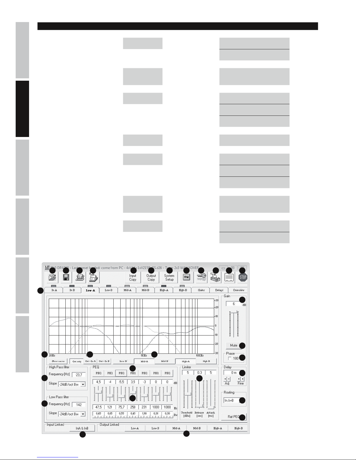
LDDPA260 SOFTWARE (BEISPIELDARSTELLUNG)
1 2 3 4 5 6 7 109 11 12
13
1415 16
17
18
19
20
8
21
25
22
24
23
26
27
28
29
Page 21

ITALIANOPOLSKIESPAÑOL
FRANCAISDEUTSCHENGLISH
21
DPA260 SOFTWARE
HINWEIS: Besteht eine Verbindung zwischen DPA260 Controller und PC/Software über USB oder RS485, sind alle Bedienelemente auf der
Frontseite des Controllers gesperrt.
1. Öffnen von auf einem Speichermedium abgelegten Controller-Preset.
2. Sichern von veränderten und neu erstellten Controller-Presets auf einem Speichermedium.
3. Übertragen von Presets auf den DPA260 Controller. Bis zu 24 Controller-Presets können auf einer DPA260 Einheit abgelegt werden.
4. Aufrufen von Controller-Presets vom DPA260.
5. Kopieren der Einstellungen eines Input-Kanals auf den anderen.
6. Kopieren der Einstellungen eines Output-Kanals auf einen anderen.
7. Konfiguration der Weichenfunktion des DPA260 Controllers (2x2 WAY XOVER + SUB, 2x3 WAY XOVER, 6 WAY XOVER)
8. Sperren der Output-Kanäle in der Software. Ist die Sperrfunktion aktiviert, besteht die Möglichkeit lediglich in den Input-Kanälen Veränderungen
vorzunehmen (Software).
9. Sperren des DPA260 Controllers (6-stelliges Passwort). Die Sperrung des Controllers bleibt auch nach Beendigen der Software und
Trennung der Verbindung mit dem PC bestehen und kann nur mit Hilfe der Software oder der Entsperrfunktion am DPA260 Controller
aufgehoben werden.
10. Umbenennung der DPA260 Controller-Einheit.
11. Umbenennung der Input- und Output-Kanäle.
12. Lösen der Verbindung der Software mit dem DPA260 Controller.
13. Aufrufen der einzelnen In- und Output-Kanäle, Gain- und Delay-Einstellungen und der Gesamtübersicht.
14. Grafische Darstellung der EQ-Einstellungen der angewählten Kanäle.
15. Zeigen der EQ-Cursor des angewählten Kanals.
16. Festlegung, ob Equalizer-Einstellungen ausschließlich der Output-Kanäle, oder der In- und Output-Kanäle summiert grafisch dargestellt werden.
17. Gain-Einstellung und -Anzeige des angewählten Kanals.
18. Stummschalten des angewählten Kanals.
19. Invertieren der Polarität des angewählten Kanals.
20. Delay-Einstellung des angewählen Kanals (0 ms, 0,02 ms...848,998 ms / 0 m, 0,0068 m...288,65932 m).
21. Auswählen der Eingangsquelle des angewählten Kanals.
22. Einstellungen des Hochpassfilters des angewählten Kanals.
23. Einstellungen des Tiefpassfilters des angewählten Kanals.
24. 7-Band Equalizer des angewählten Output-Kanals (5-Band EQ in den Input-Kanälen).
25. Einstellen der Equalizer-Charakteristik.
26. Zurückstellen der Equalizer-Einstellungen der angewählten Kanals.
27. Limiter-Einstellungen des angewählten Kanals.
28. Schaltfläche für die Verlinkung der beiden Input-Kanäle.
29. Schaltflächen für die Verlinkung von Output-Kanälen.
Modellbezeichnung: LDDPA260
Produktart: DSP-Controller
Typ: Digital
Ausführung: 6-Kanal
AD/DA-Konverter: 24 Bit
Sampling-Frequenz: 48 kHz
Frequenzgang: 20 - 20.000 Hz
Filtertyp: Butterworth, Bessel, Linkwitz-Riley
Filter Flankensteilheit: 6, 12, 18, 24 dB/Oktave
Delay (In- und Output Kanäle) 0 ms, 0,02 ms...848,998 ms / 0 m, 0,0068 m...288,65932 m
Dynamik: 111 dB (A-gewichtet)
Geräuschspannungsabstand: >106 dB
Klirrfaktor (THD): < 0,005 %
Kanalübersprechen: 107 dB (+ 20 dBu @ 1 kHz)
SPEZIFIKATIONEN
Page 22
22
DEUTSCHFRANCAIS
ESPAÑOL
ENGLISH
ITALIANO POLSKI
Max. Eingangspegel: +20 dBu (symmetrisch)
Max. Ausgangspegel: +20 dBu (symmetrisch)
Eingangsimpedanz: 27 kOhm
Ausgangsimpedanz: 120 Ohm
Bedienelemente: Nav/PM1, PM2, PM3, Enter, Escape, Utility
Edit Input A - B, Edit Output 1 – 6
Anzeigeelemente: Multifunktions-LC-Display, 2 x Aussteuerungsanzeige Eingangspegel (6 Segmente), 2 x Input Clip, 2
x Input Edit LED, 2 x Input Mute LED, 6 x Aussteuerungsanzeige Ausgangspegel (5 Segmente),
6 x Output Clip, 6 x Output Limit, 6 x Output Edit LED, 6 x Output Mute LED
Line Eingänge: 3 (2 x analog, 1 x Stereo digital)
Line Eingangsanschlüsse: XLR (symmetrisch), S/PDIF (Cinch)
Line Ausgänge: 6
Line Ausgangsanschlüsse: XLR (symmetrisch)
Schnittstelle: USB, RS485 (In & Out)
Netzanschluss: IEC-Netzbuchse
Betriebsspannung: 90 V AC - 250 V AC
Leistungsaufnahme: 14 W
Sicherung: T800mAL/250V
Abmessungen (B x H x T) 482 x 44,5 x 225 mm
HERSTELLERERKLÄRUNGEN
HERSTELLERGARANTIE & HAFTUNGSBESCHRÄNKUNG
Unsere aktuellen Garantiebedingungen und Haftungsbeschränkung finden Sie unter: http://www.adamhall.com/media/shop/downloads/
documents/manufacturersdeclarations.pdf. Im Service Fall wenden Sie sich bitte an Adam Hall GmbH, Daimlerstraße 9,
61267 Neu Anspach / E-Mail [email protected] / +49 (0)6081 / 9419-0.
KORREKTE ENTSORGUNG DIESES PRODUKTS
(Gültig in der Europäischen Union und anderen europäischen Ländern mit Mülltrennung) Dieses Symbol auf dem Produkt oder dazu-
gehörigen Dokumenten weist darauf hin, dass das Gerät am Ende der Produktlebenszeit nicht zusammen mit dem normalen Hausmüll
entsorgt werden darf, um Umwelt- oder Personenschäden durch unkontrollierte Abfallentsorgung zu vermeiden. Bitte entsorgen Sie dieses
Produkt getrennt von anderen Abfällen und führen es zur Förderung nachhaltiger Wirtschaftskreisläufe dem Recycling zu. Als Privatkunde
erhalten Sie Informationen zu umweltfreundlichen Entsorgungsmöglichkeiten über den Händler, bei dem das Produkt erwor¬ben wurde, oder
über die entsprechenden regionalen Behörden. Als gewerblicher Nutzer kontaktieren Sie bitte Ihren Lieferanten und prüfen die ggf. vertraglich
vereinbarten Konditionen zur Entsorgung der Geräte. Dieses Produkt darf nicht zusammen mit anderen gewerblichen Abfällen entsorgt werden.
CE-Konformität
Hiermit erklärt die Adam Hall GmbH, dass dieses Produkt folgenden Richtlinien entspricht (soweit zutreffend):
R&TTE (1999/5/EG) bzw. RED (2014/53/EU) ab Juni 2017
Niederspannungsrichtlinie (2014/35/EU)
EMV-Richtlinie (2014/30/EU)
RoHS (2011/65/EU)
Die vollständige Konformitätserklärung finden Sie unter www.adamhall.com.
Des Weiteren können Sie diese auch unter [email protected] anfragen.
Page 23
ITALIANOPOLSKIESPAÑOL
FRANCAISDEUTSCHENGLISH
23
FRANCAIS
VOUS AVEZ FAIT LE BON CHOIX!
Cet appareil a été développé et fabriqué en appliquant des exigences de qualité très élevées : il garantit des années de fonctionnement sans
problème. Grâce à de nombreuses années d‘expérience, LD Systems est un nom connu dans le domaine des produits audio haut de gamme.
Veuillez lire attentivement ce Manuel Utilisateur : vous apprendrez rapidement à utiliser votre appareil LD Systems de façon optimale.
Pour plus d‘informations sur LD Systems, visitez notre site Web, WWW.LD-SYSTEMS.COM
MESURES PRÉVENTIVES
1. Veuillez lire attentivement ce manuel.
2. Rangez tous les documents d‘information et d‘instructions en lieu sûr.
3. Veuillez suivre toutes les instructions
4. Observez tous les messages d‘avertissement N‘enlevez pas de l‘appareil les étiquettes de sécurité ou autres informations.
5. N‘utilisez l‘appareil que pour des applications et de la façon appropriées.
6. Utilisez exclusivement des pieds et des dispositifs de fixation stables et adaptés lorsque l‘appareil est utilisé en installation fixe. Assurez-vous
que les fixations murales ont été montées correctement, et qu‘elles sont sécurisées. Vérifiez que l‘appareil est installé en toute sécurité, et qu‘il
ne peut pas tomber.
7. Lors de l‘installation, observez les règlementations de sécurité en vigueur dans votre pays.
8. N‘installez et n‘utilisez pas l‘appareil à proximité de radiateurs, d‘accumulateurs de chaleur, de fours ou de toute autre source de chaleur.
Vérifiez que l‘appareil est installé de façon à bénéficier en permanence d‘un refroidissement efficace et qu‘il ne peut pas chauffer de façon
excessive.
9. Ne placez aucune source de flamme sur l‘appareil – par exemple, une bougie allumée.
10. Ne bloquez pas les ouïes d‘aération. Éviter toute exposition directe aux rayons du soleil !
11. N‘utilisez pas l‘appareil à proximité immédiate d‘eau (à moins qu‘il ne s‘agisse d‘un appareil conçu pour une utilisation en extérieur –
dans ce cas, respectez les instructions correspondantes ci après) Ne mettez pas l‘appareil en contact avec des matériaux, des liquides ou
des gaz inflammables.
12. Vérifiez qu‘aucune projection ou liquide ne puisse s‘introduire dans l‘appareil. Ne posez sur l‘appareil aucun objet renfermant du liquide
: vase, verre d‘eau...
13. Vérifiez qu‘aucun petit objet ne puisse tomber à l‘intérieur de l‘appareil.
14. N‘utilisez avec cet appareil que des accessoires recommandés et approuvés par le fabricant.
15. N‘ouvrez pas l‘appareil, et n‘essayez pas de le modifier.
16. Lors du branchement de l‘appareil, sécurisez le passage du câble secteur, afin d‘éviter tout dommage ou accident, par exemple quelqu‘un qui trébuche sur le câble.
17. Lors du transport, vérifiez que l‘appareil ne peut tomber, ce qui pourrait provoquer des dommages matériels et/ou corporels.
18. Si votre appareil ne fonctionne plus correctement, que de l‘eau ou des objets ont pénétré à l‘intérieur, ou qu‘il a été endommagé de
quelque façon que ce soit, éteignez-le immédiatement et débranchez sa prise secteur (s‘il s‘agit d‘un appareil alimenté). Cet appareil ne
doit être réparé que par un personnel autorisé.
19. Pour le nettoyage de l‘appareil, utilisez un chiffon sec/
20. Observez toutes les réglementations en vigueur dans votre pays pour mettre l‘appareil au rebut. Lorsque vous jetez l‘emballage de
l‘appareil, veuillez séparer plastique, papier et carton.
21. Les films plastique doivent être mis hors de portée des enfants.
APPAREILS RELIÉS AU SECTEUR
22. ATTENTION : Si le câble de l‘appareil est muni d‘un fil de terre, il doit être relié à une prise murale avec terre. Ne désactivez jamais la
mise à la terre d‘un appareil.
23. N‘allumez pas l‘appareil immédiatement s‘il a subi une grande différence de température ambiante (par exemple, lors du transport). L‘humidité
et la condensation pourraient l‘endommager. Ne mettez l‘appareil sous tension que lorsqu‘il est parvenu à la température de la pièce.
24. Avant de relier l‘appareil à la prise murale, vérifiez que la valeur et la fréquence de tension secteur sur laquelle il est réglé correspondent bien à la valeur et à la fréquence de la tension secteur locale. Si l‘appareil possède un sélecteur de tension, ne le branchez sur la prise
murale qu‘après avoir vérifié que la valeur réglée correspond à la valeur effective de la tension secteur. Si la fiche du cordon secteur ou du
bloc adaptateur livré avec votre appareil ne correspond pas au format de votre prise murale, veuillez consulter un électricien.
25. Ne piétinez pas le câble secteur. Assurez-vous que le câble secteur n‘est pas trop pincé, notamment au niveau de l‘arrière de l‘appareil
(ou de son adaptateur secteur) et de la prise murale.
26. Lors du branchement de l‘appareil, vérifiez que l‘accès au câble secteur ou au bloc adaptateur reste facile. Sortez la fiche secteur de
la prise murale dès que vous n‘utilisez pas l‘appareil pendant un certain temps, ou si vous désirez nettoyer l‘appareil. Pour ce faire, tirez
toujours sur la fiche elle-même, ou sur le bloc secteur lui-même ; ne tirez jamais sur le câble. Ne manipulez jamais le câble secteur ou
l‘adaptateur secteur avec des mains mouillées.
27. N‘éteignez/rallumez pas l‘appareil rapidement plusieurs fois de suite : vosu risquez de réduire la longévité de ses composants internes.
28. CONSEIL IMPORTANT : Ne remplacez le fusible que par un fusible de même type et du même calibre. Si le fusible fond de façon répétée,
veuillez consulter un centre de réparations agréé.
29. Pour séparer complètement l‘appareil du secteur, débranchez le cordon secteur ou l‘adaptateur de la prise murale.
30. Si votre appareil est muni d‘un connecteur secteur verrouillable (Volex), il faut d‘abord déverrouiller le mécanisme avant d‘enlever le
cordon secteur. Attention, lorsque vous retirez le câble secteur, à ne pas faire bouger l‘appareil, ce qui pourrait se traduire par un risque de
chute, de blesser quelqu‘un, ou tout autre dommage. Manipulez toujours le cordon secteur avec soin.
31. Débranchez la fiche secteur ou l‘adaptateur de la prise murale en cas d‘orage, ou si vous n‘utilisez pas l‘appareil pendant une longue période.
Page 24
24
DEUTSCHFRANCAIS
ESPAÑOL
ENGLISH
ITALIANO POLSKI
ATTENTION :
Ne démontez jamais le couvercle de l‘appareil, vous risquez de recevoir un choc électrique.
L‘appareil ne renferme aucune pièce ni composant réparable ou remplaçable par l‘utilisateur. Ne
confiez l‘entretien et la réparation qu‘à un personnel qualifié.
Le pictogramme en forme de triangle équilatéral contenant un éclair terminé d‘une flèche avertit l‘utilisateur de la présence
d‘une tension dangereuse à l‘intérieur de l‘appareil, tension susceptible de provoquer un choc électrique.
Le pictogramme en forme de triangle équilatéral renfermant un point d‘exclamation signale à l‘utilisateur la présence
d‘instructions importantes concernant l‘utilisation ou l‘entretien de l‘appareil.
ATTENTION ! Ce symbole correspond à des surfaces chaudes. En cours de fonctionnement, certaines parties de l’appareil peuvent
devenir chaudes. Après utilisation, ne manipulez ou ne transportez l’appareil qu’au bout de 10 minutes de refroidissement.
Attention ! Cet appareil est conçu pour une utilisation à une altitude maximale de 2000 m au-dessus du niveau de la mer.
Attention ! Ce produit ne convient pas à une utilisation dans les climats tropicaux.
Pour éviter tout risque de traumatisme auditif, évites d‘écouter à fort volume sonore pendant de longues périodes.
Un niveau d‘écoute trop élevé, même bref, peut provoquer des dommages aux oreilles. Veuillez maintenir le niveau d‘écoute à
un niveau raisonnable.
ATTENTION ! NIVEAUX SONORES ÉLEVÉS SUR LES PRODUITS AUDIO
Cet appareil a été conçu en vue d‘une utilisation professionnelle. L‘utilisation commerciale de cet appareil est soumise aux réglementations
et directives en vigueur dans votre pays en matière de prévention d‘accident. En tant que fabricant, Adam Hall est tenu de vous avertir
formellement des risques relatifs à la santé. Risques provoqués par une exposition prolongée à des niveaux sonores élevés : Lors de
l‘utilisation de ce produit, il est possible d‘atteindre des niveaux de pression sonore (exprimés en dB SPL) élevés, susceptibles de provoquer
des dommages auditifs irréparables chez les artistes, les techniciens et le public. Évitez toute exposition prolongée à des niveaux de
pression sonore élevés (supérieurs à 90 dB SPL).
Page 25
ITALIANOPOLSKIESPAÑOL
FRANCAISDEUTSCHENGLISH
25
CONNECTEURS, CONTRÔLES ET INDICATEURS
1
2
3
4
5
6 7
9
12
13
14
15
16
17
18
19
20 21
8
10
11
1
DISPLAY
Écran LCD rétro-éclairé multifonctions, 2 lignes de 24 caractères.
2
UTILITY
Appuyez sur la touche UTILITY pour accéder aux différents menus de réglage de l'appareil.
3
NAV/PM1
Après avoir appuyé sur la touche UTILITY, la molette NAV/PM1 permet de passer d'un élément à un autre dans le menu principal et les
sous-menus.
4
ENTER
Appuyez sur ENTER pour descendre d'un niveau hiérarchique dans le menu et pour valider les modifications apportées à des paramètres.
5
ESC
Appuyez sur ESC pour remonter d'un niveau hiérarchique dans le menu et pour revenir à l'affichage principal.
6
PM2
Le potentiomètre PM2 sert à modifier les valeurs de paramètres dans un élément de menu. Pour valider cette nouvelle valeur, appuyez sur
la touche ENTER.
7
PM3
Le potentiomètre PM3 sert à modifier les valeurs de paramètres dans un élément de menu. Pour valider cette nouvelle valeur, appuyez sur
la touche ENTER.
Page 26
26
DEUTSCHFRANCAIS
ESPAÑOL
ENGLISH
ITALIANO POLSKI
8
INPUT METER A / B
Indicateurs de niveau LED à 7 segments, pour les canaux d'entrée A et B. Dès que la LED rouge CLIP, en haut de l'indicateur de niveau,
s'allume, réduisez le niveau de sortie de la source de signal audio (par exemple, table de mixage), afin d'éviter toute distorsion (niveau
maximal d'entrée : +20 dBu).
9
OUTPUT METER 1 - 6
Indicateurs de niveau LED à 7 segments, pour les canaux de sortie 1 à 6. Afin d'éviter toute distorsion, réduisez le niveau de sortie sur le
canal correspondant dès que la LED rouge CLIP s'allume. La LED jaune LIMIT s'allume lorsque le signal de sortie du canal correspondant est
traité dans le limiteur intégré (ses paramètres sont optimisés).
10
EDIT-LED
Appuyez brièvement sur la touche n°12 du canal d'entrée ou de sortie désiré afin de passer en mode d'édition du canal. La LED bleue
du canal sélectionné s'allume. Pour quitter le mode d'édition du canal, appuyez de nouveau brièvement sur la touche n°12. La LED bleue
s'éteint.
11
MUTE-LED
Maintenez enfoncée pendant environ 2 secondes la touche n°12 du canal d'entrée ou de sortie désiré afin de passer en mode Mute (coupure
du signal). La LED rouge MUTE du canal sélectionné s'allume. Pour désactiver cette coupure du signal, appuyez de nouveau pendant environ 2
secondes sur la touche n°12. Le signal audio est rétabli, et la LED rouge MUTE s'éteint.
12
TOUCHES FONCTION INPUT A / B ET OUTPUT 1 - 6
Appuyez sur la touche désirée pour appeler les fonctions décrites dans les points 10 et 11.
13
USB-PORT
Le port USB sert à éditer et gérer confortablement toutes les fonctions et les presets du contrôleur DSP LDDPA260 depuis un PC sous
Windows. Le logiciel de gestion et les pilotes pour les systèmes d'exploitation Windows sont livrés avec l'appareil ; vous pouvez également
les télécharger, ainsi qu'un certain nombre de presets correspondant à la plupart des enceintes LD Systems, depuis notre site Web
WWW.LD-SYSTEMS.COM.
14
ON
Interrupteur On/Off pour la tension d'alimentation de l'appareil.
15
EMBASE SECTEUR IEC AVEC PORTE-FUSIBLE INTÉGRÉ
Reçoit la tension secteur alimentant l'appareil. Le câble secteur correspondant est livré. AVERTISSEMENT IMPORTANT : Ne remplacez le
fusible secteur que par un modèle du même type de de la même valeur (T800mAL/250V) ! Si le fusible fond de façon répétée, veuillez
consulter un centre de réparations agréé.
16
GROUND LIFT
Ce sélecteur de levage de masse permet d'éviter des ronflettes lorsque les appareils audio connectés possèdent des potentiels de masse différents.
17
RS485 IN
Ce port, utilisé conjointement à l'adaptateur USB vers RS-485 LDDPA260RC, permet de piloter le LDDPA260 via un multipaire XLR standard,
via un PC sous Windows.
18
RS485 OUT
Ce port renvoie le signal de pilotage vers un ou plusieurs autres contrôleurs DSP LDDPA260.
19
S/PDIF
Entrée audionumérique stéréo au format S/PDIF coaxial
20
OUTPUTS 1 - 6
Sorties audio symétriques sur embases XLR 3 points mâles.
Page 27
ITALIANOPOLSKIESPAÑOL
FRANCAISDEUTSCHENGLISH
27
21
INPUTS A + B
Entrées audio symétriques sur embases XLR 3 points femelles.
STRUCTURE DU MENU UTILITY
Display: Display:
System Utilities
-> ENTER ->
<- ESC
Program Utilities
-> ENTER ->
<- ESC
Main Menu UTILITY NAV/PM1
Interface
Utilities
-> ENTER ->
<- ESC
Security Utilities
-> ENTER ->
<- ESC
STRUCTURE DU MENU SYSTEM UTILITIES
Display: Display: Display:
System Utilities
-> ENTER ->
<- ESC
NAV/PM1 System Setup
-> ENTER ->
<- ESC
PM2/3 2x2 WAY + SUB -> ENTER <-
2x3 WAY XOVER -> ENTER <-
6 WAY XOVER -> ENTER <-
Input Routing
-> ENTER ->
<- ESC
PM2/3 Source : Analog -> ENTER <-
Source : Digital -> ENTER <-
Power-On
Procedure
-> ENTER ->
<- ESC
PM2/3 Fade-In : On -> ENTER <-
Fade-In : Off -> ENTER <-
Delay Units
-> ENTER ->
<- ESC
PM2/3
Unit : Distan-
ce(m)
-> ENTER <-
Unit : Time(ms) -> ENTER <-
Ramps on
changes
-> ENTER ->
<- ESC
PM2/3 Ramps : On -> ENTER <-
Ramps : Off -> ENTER <-
Software
Version
-> ENTER ->
<- ESC
Version : V1.xx <- ESC
Page 28
28
DEUTSCHFRANCAIS
ESPAÑOL
ENGLISH
ITALIANO POLSKI
Display: Display: Display: Display:
Program
Utilities
-> ENTER ->
<- ESC
NAV/PM1
Recall a
Program
-> ENTER ->
<- ESC
PM2/3 01 - 24
-> 2x ENTER <-
<- ESC
Save a
Program
-> ENTER ->
<- ESC
PM2/3 01 - 24
-> ENTER ->
<- ESC
Set Program
Name
NAV/PM1
PM2/3
-> 2x ENTER <-
<- ESC
Delete a
Program
-> ENTER ->
<- ESC
PM2/3 01 - 24
-> 2x ENTER <-
<- ESC
Display: Display: Display: Display: Display:
Interface
Utilities
-> ENTER ->
<- ESC
Interface
Setup
-> ENTER ->
<- ESC
PM2/3 Source : USB
-> ENTER
<- ESC
Source :
RS485
-> ENTER ->
<- ESC
NAV/PM1
Remote ID
Num = xx
PM2/3
Remote ID
Num = 01
- 32
-> ENTER
<- ESC
Display: Display: Display: Display: Display: Display:
Security
Utilities
-> ENTER ->
<- ESC
NAV/PM1
Show
Parameter
-> ENTER ->
<- ESC
PM2/3
Parameter
will be
shown
-> ENTER <-
Parameter
will not be
shown
-> ENTER <-
Lock Unit
-> ENTER ->
<- ESC
PM2/3 Lock : On
-> ENTER ->
<- ESC
Main Menu
(Menu
locked)
(to unlock)
UTILITY ->
Lock Unit -> ENTER -> PM2/3 Lock : Off -> ENTER <-
Lock : Off -> ENTER <-
User
Password
-> ENTER ->
<- ESC
NAV/PM1
PM2/3
User
Password
[000000]
-> ENTER ->
<- ESC
NAV/PM1
PM2/3
New
Password
[xxxxxx]
-> ENTER ->
<- ESC
NAV/PM1
PM2/3
Confirm
Password
[xxxxxx]
-> ENTER <-
Enable
Password
-> ENTER ->
<- ESC
PM2/3
Password :
Disable
-> ENTER
Password :
Enable
-> ENTER ->
Main Menu
(Menu
locked)
(to unlock)
UTILITY ->
User
Password
[xxxxxx]
-> ENTER <-
STRUCTURE DU MENU PROGRAM UTILITIES, INTERFACE UTILITIES, SECURITY UTILITIES
Page 29
ITALIANOPOLSKIESPAÑOL
FRANCAISDEUTSCHENGLISH
29
STRUCTURE DU MENU INPUTS A/B
MENÚ OUTPUTS 1-6
Display: Display:
EDIT OUTPUT
1-6:
-> EDIT
1-6 ->
NAV/PM1 Out 1-6 HPF -> ENTER -> PM2 KHz <- ESC
PM3 No Cut-Off <- ESC
Butwrth 6 dB <- ESC
Butwrth 12 dB <- ESC
Lnk/Ril 12 dB <- ESC
Bessel 12 dB <- ESC
Butwrth 18 dB <- ESC
Butwrth 24 dB <- ESC
Lnk/Ril 24 dB <- ESC
Bessel 24 dB <- ESC
Out 1-6 LPF -> ENTER -> PM2 KHz <- ESC
PM3 No Cut-Off <- ESC
Butwrth 6 dB <- ESC
Butwrth 12 dB <- ESC
Lnk/Ril 12 dB <- ESC
Bessel 12 dB <- ESC
Butwrth 18 dB <- ESC
Butwrth 24 dB <- ESC
Lnk/Ril 24 dB <- ESC
Bessel 24 dB <- ESC
Out 1-6 EQ1-EQ7 -> ENTER -> NAV/PM1 KHz <- ESC
PM2 BW <- ESC
PM3 dB <- ESC
Display: Display:
EDIT INPUT
A/B:
-> EDIT
A/B ->
NAV/PM1
Input-A/B
EQ1-EQ5
-> ENTER -> NAV/PM1 KHz <- ESC
PM2 BW <- ESC
PM3 dB <- ESC
Input-A/B
Gain
-> ENTER -> PM2/3 dB <- ESC
Input-A/B
Delay
-> ENTER -> PM2/3
m/ms
(0 m...288,65932 m / 0 ms...848,998 ms)
<- ESC
Page 30
30
DEUTSCHFRANCAIS
ESPAÑOL
ENGLISH
ITALIANO POLSKI
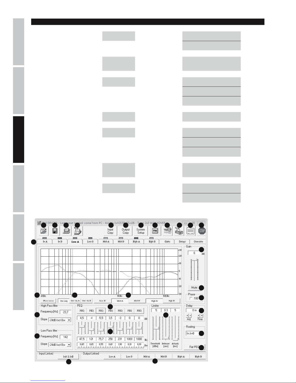
LOGICIEL LDDPA260 (COPIE D’ÉCRAN)
1 2 3 4 5 6 7 109 11 12
13
1415 16
17
18
19
20
8
21
25
22
24
23
26
27
28
29
Out 1-6 Vu-Meter -> ENTER -> PM2/3 Level <- ESC
Limiter Act <- ESC
Out 1-6 Name -> ENTER ->
NAV/PM1
PM2/3
Name = xxxxxx -> ENTER <-
Out 1-6 Source -> ENTER -> PM2/3 InA <- ESC
InB <- ESC
InA+InB <- ESC
Out 1-6 Gain -> ENTER -> PM2/3 dB <- ESC
Out 1-6 Limiter -> ENTER -> NAV/PM1 Attack ms <- ESC
PM2 Release s <- ESC
PM3 dBu <- ESC
Out 1-6 Delay -> ENTER -> PM2/3
m/ms
(0 m...288,65932 m /
0 ms...848,998 ms)
<- ESC
Out 1-6 Polarity -> ENTER -> PM2/3 Normal <- ESC
Invert <- ESC
Display: Display:
Page 31

ITALIANOPOLSKIESPAÑOL
FRANCAISDEUTSCHENGLISH
31
LOGICIEL DPA260
PRÉCISION : Lorsque le contrôleur DSP DPA260 est piloté par logiciel depuis un PC via USB ou RS485, tous les contrôles en face avant sont
désactivés.
1. Ouverture d'un preset de contrôleur depuis un support mémoire.
2. Enregistrement d'un preset de contrôleur modifié ou nouveau sur un support mémoire.
3. Transfert de presets vers le contrôleur DPA260. Le DPA260 possède 24 mémoires pour presets.
4. Rappel de presets depuis le contrôleur DP1260.
5. Copie des valeurs de paramètres d'un canal d'entrée sur l'autre.
6. Copie des valeurs de paramètres d'un canal de sortie sur un autre.
7. Configuration des filtres du contrôleur DPA260 (2x2 WAY XOVER + SUB, 2x3 WAY XOVER, 6 WAY XOVER).
8. Verrouillage des canaux de sortie dans le logiciel. Lorsque la fonction de verrouillage est activée, seule la modification des paramètres
des canaux d'entrée reste possible (logiciel).
9. Verrouillage du contrôleur DPA260 (mot de passe à 6 caractères) Cette fonction de verrouillage reste activée même après avoir quitté le
logiciel et séparé le contrôleur du PC. Elle ne peut être désactivée que via le logiciel ou la fonction de verrouillage du DPA260 lui-même.
10. Attribution d'un nom au contrôleur DPA260.
11. Attribution de noms aux canaux d'entrée et de sortie.
12. Coupure de la liaison entre le logiciel et le contrôleur DPA260.
13. Appel d'un canal d'entrée ou de sortie à la fois, réglage de gain et de délai, vue générale
14. Représentation graphique des paramètres d'égalisation sur les canaux sélectionnés
15. Visualisation du curseur d'EQ sur le canal sélectionné.
16. Détermination de la visualisation graphique d'égalisation : seulement le canal de sortie, ou le canal d'entrée et le canal de sortie sommés.
17. Réglage de gain et visualisation du gain sur le canal sélectionné.
18. Coupure (Mute) du canal sélectionné.
19. Inversion de la polarité sur le canal sélectionné.
20. Réglage du délai sur le canal sélectionné (0 ms, 0,02 ms...848,998 ms / 0 m, 0,0068 m...288,65932 m).
21. Choix de la source d'entrée sur le canal sélectionné.
22. Réglage du filtre passe-haut sur le canal sélectionné.
23. Réglage du filtre passe-bas sur le canal sélectionné.
24. Égaliseur 7 bandes du canal de sortie sélectionné (5 bandes sur les canaux d'entrée).
25. Réglage du type d'égaliseur.
26. Réinitialisation des paramètres de l'égaliseur sur le canal sélectionné.
27. Réglages du limiteur sur le canal sélectionné
28. Bouton de couplage des deux canaux d'entrée
29. Boutons de couplage de canaux de sortie.
CARACTÉRISTIQUES
Référence Modèle : LDDPA260
Type de Produit : Contrôleur DSP
Type : numérique
Type : 6 canaux
Convertisseurs A/N et N/A : 24 bits
Fréquence d'échantillonnage : 48 kHz
Réponse en Fréquence : 20 Hz à 20 kHz
Types de filtres disponibles : Butterworth, Bessel, Linkwitz-Riley
Pentes des filtres : 6, 12, 18, 24 dB/octave
Delay (canaux d’entrée et de sortie) : 0 ms, 0,02 ms...848,998 ms / 0 m, 0,0068 m...288,65932 m
Dynamique : 111 dB (pondéré A)
Rapport signal/bruit : >106 dB
Taux de distorsion (THD) : < 0,005 %
Séparation des Canaux : 107 dB (à + 20 dBu, 1 kHz)
Niveau Maximal d'Entrée : +20 dBu (symétrique)
Page 32
32
DEUTSCHFRANCAIS
ESPAÑOL
ENGLISH
ITALIANO POLSKI
DECLARATIONS
GARANTIE FABRICANT & LIMITATION DE RESPONSABILITÉ
Nos conditions actuelles de garantie et de limitation de responsabilité sont disponibles à l‘adresse suivante : http://www.adamhall.com/media/
shop/downloads/documents/manufacturersdeclarations.pdf. Pour les réparations, veuillez contacter Adam Hall GmbH, Daimlerstraße 9,
61267 Neu Anspach / E-Mail [email protected] / +49 (0)6081 / 9419-0.
TRI ET MISE AUX DÉCHETS CORRECTE DE CE PRODUIT
(Valid in the European Union and other European countries with waste separation)
(Applicable dans l‘Union Européenne et les autres pays européens pratiquant le tri des déchets) La présence de ce symbole sur le
produit ou sur la documentation correspondante indique qu‘en fin de vie, le produit ne doit pas être jeté avec les déchets normaux, afin
d‘éviter tout dommage à l‘environnement ou aux personnes consécutive à une élimination non contrôlée des déchets. Séparez-le des autres types de déchets et recyclez-le, afin de promouvoir la réutilisation durable des ressources naturelles. Nous conseillons aux utilisateurs
non professionnels de contacter le revendeur chez qui ils ont acheté le produit, ou un représentant gouvernemental local, pour plus de
détails sur le lieu de collecte et la façon de recycler cet appareil dans le meilleur respect de l‘environnement possible.. Nous invitons les
utilisateurs professionnels à contacter leur fournisseur et à vérifier les termes et conditions de leur contrat d‘achat. Ce produit ne doit pas
être mélangé à d‘autres déchets commerciaux lors de la collecte.
Conformité CE
La société Adam Hall GmbH déclare par la présente que ce produit est compatible avec les régulations suivantes (le cas échéant) :
R&TTE (1999/5/EG) et RED (2014/53/EU) à partir de juin 2017
Directive basse tension (2014/35/EU)
Directive CEM (2014/30/EU)
RoHS (2011/65/EU)
La Déclaration de Conformité complète est disponible sur le site Web www.adamhall.com.
Pour toute information complémentaire, contactez-nous : [email protected].
Niveau Maximal d'Entrée : +20 dBu (symétrique)
Impédance d'Entrée : 27 kohms
Impédance de sortie: 120 ohms
Contrôles : Potentiomètres Nav/Par1, Par2, Par3, touches Enter, Escape, Utility
Edit Input 1 - 2, Edit Output 1 - 6
Visualisation : Écran LCD multifonctions, 2 indicateurs de niveau d'entrée (6 segments), 2 LED Input Clip, 2 LED
Input Edit, 2 LED Input Mute, 6 indicateurs de niveau de sortie (5 segments),
6 LED Output Clip, 6 LED Output Limit, 6 LED Output Edit, 6 LED Output Mute
Entrées ligne : 3 (2 x analogiques, 1 x numérique stéréo)
Connecteurs d'entrée ligne XLR (symétrique), S/PDIF (cinch)
Sorties ligne : 6
Connecteurs de sortie ligne : XLR (symétrique)
Ports : USB, RS485 (entrée & sortie)
Connexion Secteur : Embase secteur au format IEC
Tension Secteur : 90 à 250 Volts
Consommation Électrique : 14 W
Fusible : T800mAL/250V
Dimensions (LxHxP) 482 x 44,5 x 225 mm
Page 33
ITALIANOPOLSKIESPAÑOL
FRANCAISDEUTSCHENGLISH
33
ESPAÑOL
¡GRACIAS POR ELEGIR LD-SYSTEMS!
Este equipo está diseñado y fabricado con los estándares de calidad más exigentes, para garantizar un correcto funcionamiento durante
muchos años. Los productos de LD-Systems se caracterizan por su gran calidad, avalada por el prestigio de la marca y una dilatada experiencia como fabricante. Lea atentamente este manual de usuario para poder aprovechar rápidamente toda la funcionalidad de su nuevo
producto de LD Systems.
Si desea obtener información sobre LD-SYSTEMS, visite nuestro sitio web WWW.LD-SYSTEMS.COM
MEDIDAS DE SEGURIDAD
1. Lea atentamente las instrucciones de este manual.
2. Guarde toda la información en un lugar seguro para futuras consultas.
3. Siga las instrucciones indicadas.
4. Siga todas las advertencias. No quite las instrucciones de seguridad ni cualquier otra información indicada en el equipo.
5. Utilice el equipo únicamente según la finalidad prevista.
6. Utilice solo soportes y fijaciones que sean robustos y adecuados cuando instale el equipo en instalaciones fijas. Asegúrese de que los
soportes de pared están correctamente instalados y firmemente fijados. Asegúrese de que el equipo está sólidamente instalado y no se
puede caer.
7. Al instalar el equipo, respete las normas de seguridad aplicables en su país.
8. Evite instalar el equipo cerca de radiadores, acumuladores de calor, estufas o cualquier otra fuente de calor. Asegúrese de que el equipo
esté instalado en un lugar con ventilación suficiente para evitar cualquier sobrecalentamiento.
9. No coloque sobre el equipo fuentes de llamas sin protección, por ejemplo, velas encendidas.
10. Evite bloquear las rejillas de ventilación. ¡Evite la luz solar directa!
11. No utilice este equipo cerca del agua (excepto los equipos específicamente diseñados para uso en exterior, en cuyo caso tenga en
cuenta las indicaciones mencionadas a continuación). No exponga este equipo a materiales, líquidos o gases inflamables.
12. Evite exponer el equipo a gotas o salpicaduras que puedan caer dentro del mismo. No coloque recipientes llenos de líquido, como
floreros o vasos, sobre el equipo.
13. Asegúrese de no dejar caer ningún objeto dentro del equipo.
14. Emplee el equipo únicamente con los accesorios recomendados por el fabricante.
15. No abra el equipo ni intente modificarlo.
16. Una vez conectado el equipo, compruebe que en toda la longitud del cableado no hay peligro de que provoque una caída, por ejemplo.
17. Durante el transporte, asegúrese de que el equipo no se caiga y pueda causar daños personales o materiales.
18. Si el equipo no funciona correctamente, o si se ha vertido líquido sobre él, o si un objeto ha caído en su interior o si ha sufrido algún
desperfecto, apague inmediatamente el equipo y desenchufe el cable eléctrico (si se trata de un equipo activo). Únicamente un técnico
especialista debe reparar el equipo.
19. Para limpiar el equipo utilice un paño seco.
20. Procure seguir las normas vigentes en su país sobre reciclaje de desechos. Separe los componentes de plástico, papel y cartón del
paquete para reciclarlos en sus contenedores respectivos.
21. No deje las bolsas de plástico al alcance de los niños.
PARA LOS EQUIPOS CON TOMA ELÉCTRICA
22. ADVERTENCIA: Si el cable eléctrico está provisto de un contacto de protección, debe conectarse a una toma eléctrica con conexión a
tierra. No desactivar nunca esta conexión de protección a tierra del cable eléctrico.
23. Si el equipo ha estado expuesto a un cambio brusco de temperatura (por ejemplo, después del transporte), no lo encienda inmediatamente. La condensación o la humedad podrían dañar el equipo. Deje que el equipo alcance la temperatura ambiente antes de encenderlo.
24. Antes de conectar el cable eléctrico a la toma de corriente, compruebe si la tensión y la frecuencia del suministro eléctrico coinciden
con las especificaciones de este equipo. Si el equipo dispone de un selector de tensión, antes de enchufarlo a la red eléctrica, asegúrese de
que el valor seleccionado coincide con la tensión de suministro. Si el enchufe o el adaptador de corriente no encajan en la toma eléctrica,
consulte a un electricista.
25. Asegúrese de que el cable eléctrico no está pinzado. Evite que el cable resulte pellizcado, sobre todo en los extremos de conexión al
equipo y en la toma eléctrica.
26. Al conectar el equipo, asegúrese de que el cable eléctrico o el adaptador de corriente estén siempre accesibles. Desconecte el equipo
de la toma de corriente cuando no esté en uso o antes de limpiarlo. Para ello, desconecte el cable eléctrico y el adaptador de corriente del
conector del equipo en vez de desenchufar el cable de la toma eléctrica. No tocar el cable eléctrico ni el adaptador de corriente con las
manos húmedas.
27. No encienda y apague el equipo en cortos intervalos de tiempo, ya que se reduce así la vida útil del sistema.
28. NOTA IMPORTANTE: Sustituya los fusibles únicamente por otros del mismo tipo y de las mismas características. Si el fusible se funde
continuamente, póngase en contacto con un servicio técnico autorizado.
29. Para desconectar completamente el equipo de la tensión eléctrica, desenchufe el cable eléctrico o el adaptador de corriente de la toma eléctrica.
30. Si el equipo dispone de un enchufe eléctrico Volex, deberá desbloquearse el Volex del equipo para desenchufarlo. Esto implica que un
tirón en el cable eléctrico puede desplazar el equipo y provocar daños personales o materiales. Por tanto, asegúrese de instalar los cables
con sumo cuidado.
Page 34
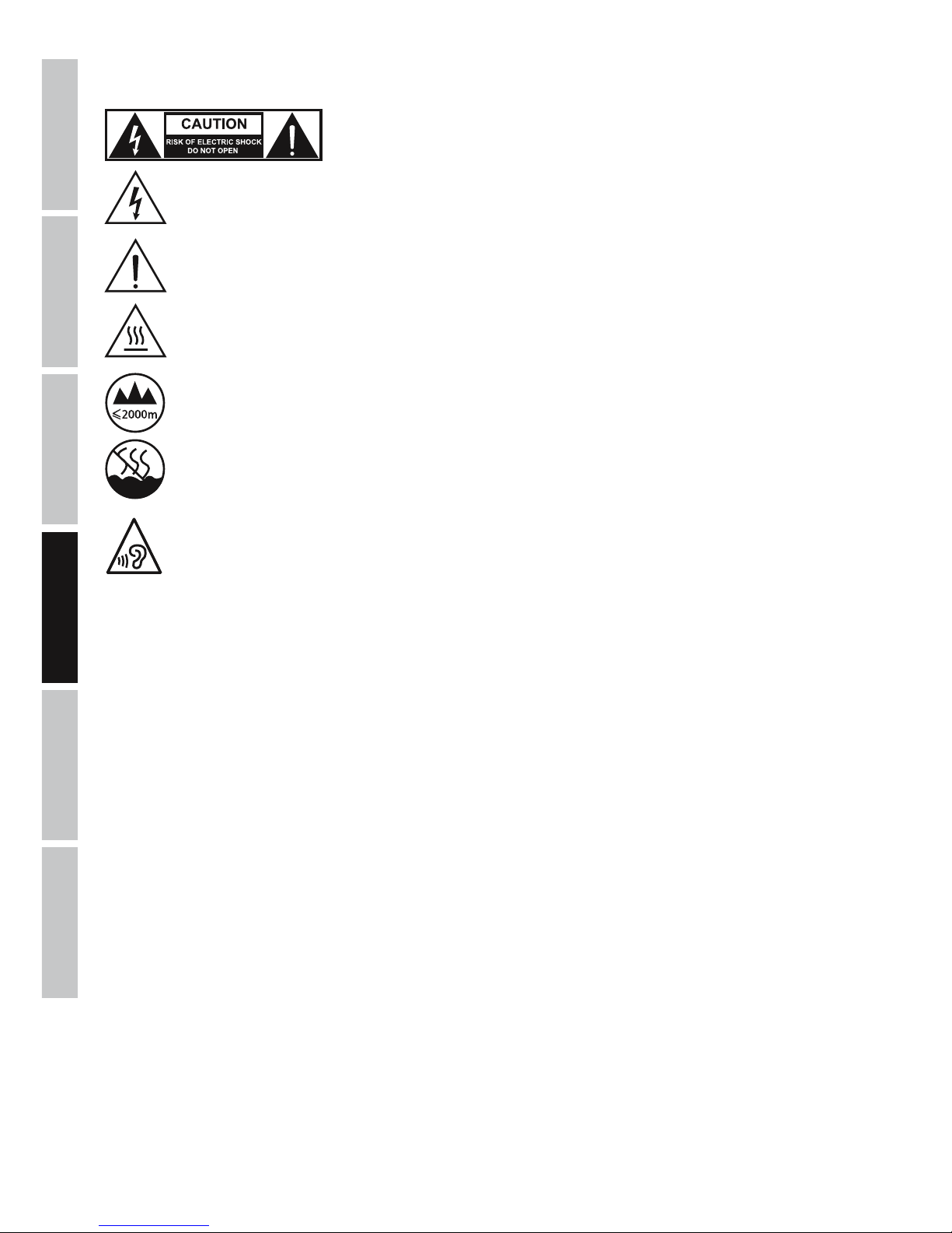
34
DEUTSCHFRANCAIS
ESPAÑOL
ENGLISH
ITALIANO POLSKI
31. Si es probable que caiga un rayo por una tormenta eléctrica o si no va a emplear el equipo durante mucho tiempo, desenchufe el cable
eléctrico y el adaptador de corriente.
ATENCIÓN:
Para evitar el riesgo de descarga eléctrica, no retire la tapa. El equipo no contiene elementos que
el usuario pueda reparar o sustituir. Para cualquier tarea de mantenimiento o reparación, acuda a
un técnico cualificado.
El símbolo de rayo dentro de un triángulo equilátero advierte al usuario de la presencia de tensiones peligrosas sin aislamiento
dentro del equipo que pueden causar una descarga eléctrica.
El símbolo de exclamación dentro de un triángulo equilátero advierte al usuario de la existencia de importantes instrucciones
de uso y mantenimiento.
¡Advertencia! Este símbolo indica la presencia de superficies calientes. Durante el funcionamiento, algunas partes de la
carcasa pueden llegar a calentarse bastante. Por ello, una vez apagado el equipo, espere al menos 10 minutos antes de
manipularlo o transportarlo.
¡Advertencia! Este equipo está diseñado para ser utilizado a una altura que no supere los 2000metros sobre el nivel del mar.
¡Advertencia! Este equipo no está diseñado para funcionar en climas tropicales.
Para evitar posibles daños auditivos, evite la exposición a volúmenes altos durante un tiempo prolongado.
Un volumen alto, incluso durante un breve espacio de tiempo, puede provocar pérdida de audición. Mantenga siempre el
volumen a un nivel que le resulte agradable.
¡ADVERTENCIA: ALTO VOLUMEN!
Este equipo se destina a un uso profesional. Por consiguiente, si se aplica a un uso comercial, estará sujeto a las normas y reglamentos
de la Asociación para la prevención de accidentes de su sector profesional. Como fabricante, Adam Hall tiene la obligación de informar
formalmente a los usuarios de la existencia de posibles riesgos para la salud. Daños auditivos por exposición prolongada a un nivel SPL
alto: este equipo puede generar fácilmente un nivel de presión sonora (SPL) lo suficientemente elevado como para causar daños auditivos
permanentes a los artistas, el personal de producción y el público. Deben tomarse precauciones para evitar la exposición prolongada a un
SPL de más de 90dB.
Page 35
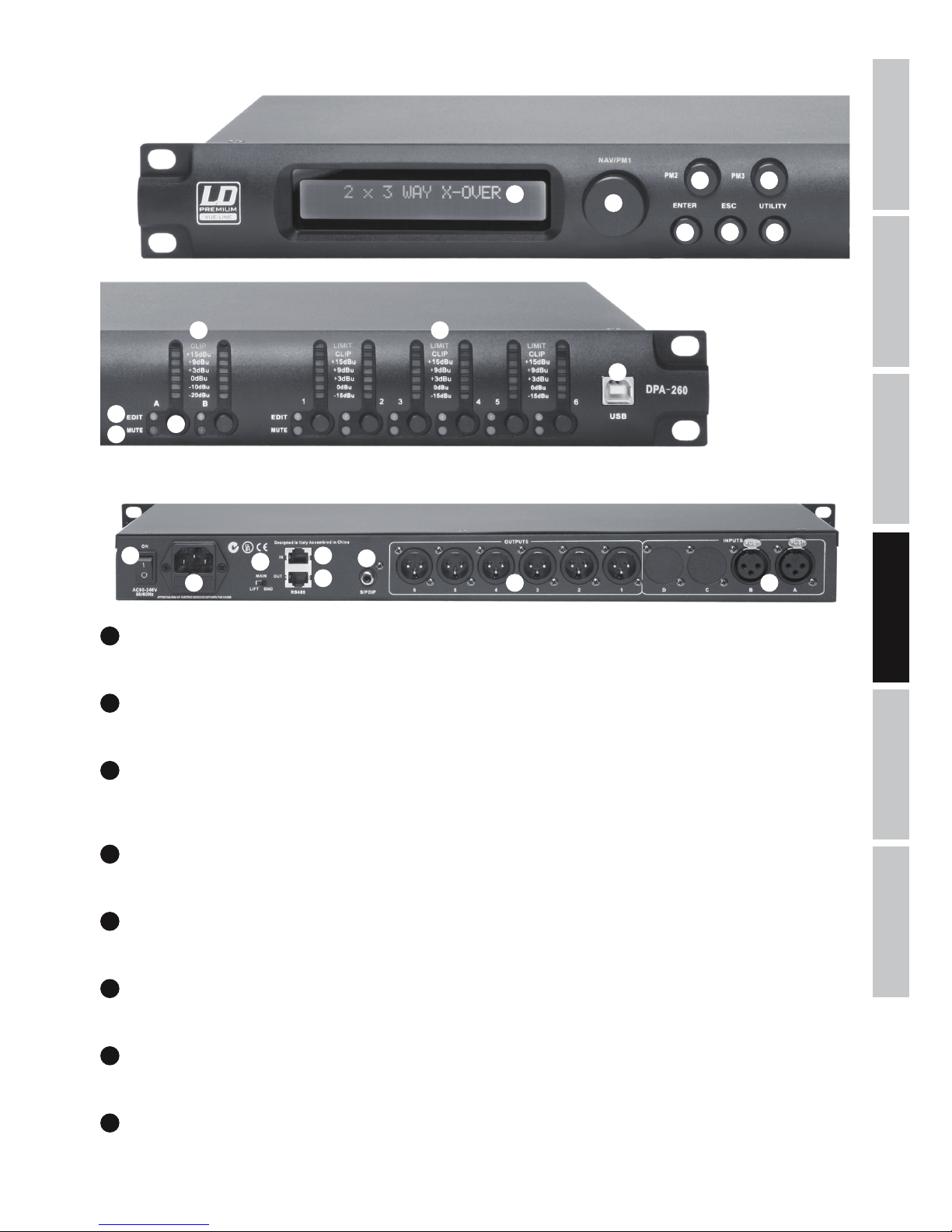
ITALIANOPOLSKIESPAÑOL
FRANCAISDEUTSCHENGLISH
35
CONEXIONES, CONTROLES E INDICADORES
1
2
3
4
5
6 7
9
12
13
14
15
16
17
18
19
20 21
8
10
11
1
DISPLAY
Pantalla LCD retroiluminada de 2 x 24caracteres.
2
UTILITY
Pulse el botón UTILITY para poder realizar cambios en el menú de ajustes del equipo.
3
NAV/PM1
Después de pulsar el botón UTILITY, utilice el control giratorio NAV/PM1 para seleccionar entre las distintas opciones del menú principal y de
los submenús.
4
ENTER
Pulse ENTER para ir al nivel siguiente del menú y para confirmar los cambios realizados en los parámetros.
5
ESC
Pulse el botón ESC para ir al nivel anterior del menú y para volver a la pantalla principal.
6
PM2
Utilice el control giratorio PM2 para cambiar los parámetros de una opción de menú. Confirme con el botón ENTER.
7
PM3
Utilice el control giratorio PM3 para cambiar los parámetros de una opción de menú. Confirme con el botón ENTER.
8
INPUT METER A / B
Vúmetros de LEDs de 7segmentos del nivel de señal de los canales de entrada A y B. Si se ilumina el LED CLIP rojo en el extremo superior
del vúmetro, reduzca el nivel de salida del reproductor (por ej., de la mesa de mezclas) para evitar que sature (nivel máx.: +20dBu).
Page 36
36
DEUTSCHFRANCAIS
ESPAÑOL
ENGLISH
ITALIANO POLSKI
9
OUTPUT METER 1 - 6
Vúmetros de LEDs de 7segmentos del nivel de señal de los canales de salida1 a 6. Si se ilumina el LED CLIP rojo, reduzca el nivel del canal
de salida correspondiente para evitar que sature. El LED LIMIT amarillo se ilumina cuando el limitador integrado limita la señal de salida del
canal correspondiente (el limitador se configurará según los componentes del sistema).
10
EDIT-LED
Pulse brevemente el botón (12) del canal de entrada o de salida correspondiente para entrar en el modo Edición del canal. El LED EDIT azul
del canal seleccionado se iluminará. Para salir del modo Edición del canal, pulse brevemente el botón (12). El LED EDIT azul se apagará.
11
MUTE-LED
Pulse el botón (12) de un canal de entrada o de salida durante unos 2segundos para silenciar el sonido de dicho canal. El LED MUTE rojo
del canal seleccionado se iluminará. Para dejar de silenciar un canal, pulse el botón (12) durante unos 2segundos. La señal de audio se oirá
de nuevo y el LED MUTE rojo se apagará.
12
BOTÓN DE FUNCIÓN DE LAS ENTRADAS A/B Y LAS SALIDAS 1 - 6
Pulse este botón para activar las funciones que se describen en los puntos10 y 11 anteriores.
13
USB-PORT
El puerto USB se utiliza para conectar un ordenador Windows y poder gestionar y editar cómodamente todas las funciones y preajustes
del procesador digital de señales LDDPA260. El software y los controladores para el sistema operativo Windows se incluyen con el equipo,
aunque también se pueden descargar, al igual que los preajustes para varios altavoces de LD Systems, desde nuestro sitio web
WWW.LD-SYSTEMS.COM.
14
ON
Interruptor de encendido/apagado del equipo.
15
TOMA IEC CON PORTAFUSIBLES INTEGRADO
Toma eléctrica para alimentar el equipo. Se suministra con el cable eléctrico apropiado. INFORMACIÓN IMPORTANTE: Sustituya el fusible
únicamente por otro del mismo tipo y características (T800mAL/250V). Si el fusible se fundiera continuamente, póngase en contacto con un
servicio técnico autorizado.
16
GROUND LIFT
Evita los bucles de masa cuando los equipos están conectados a diferentes potenciales de tierra.
17
RS485 IN
Al conectar el adaptador de USB a RS-485 LDDPA260RC , este conector permite el control remoto del LDDPA260 desde el FOH a través de
un cable multipar XLR y un ordenador con Windows.
18
RS485 OUT
Se utiliza para reenviar la señal de control a uno o varios procesadores LDDPA260.
19
S/PDIF
Entrada estéreo digital por cable coaxial en formato S/PDIF.
20
OUTPUTS 1 - 6
Salidas de audio balanceadas por XLR macho de 3pines.
21
INPUTS A + B
Entradas de audio balanceadas por XLR hembra de 3pines.
Page 37
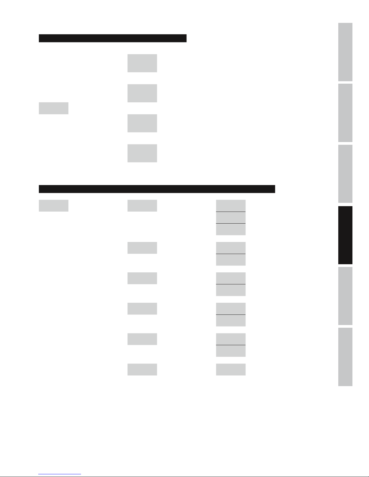
ITALIANOPOLSKIESPAÑOL
FRANCAISDEUTSCHENGLISH
37
MENÚ UTILITY
Display: Display:
System Utilities
-> ENTER ->
<- ESC
Program Utilities
-> ENTER ->
<- ESC
Main Menu UTILITY NAV/PM1
Interface
Utilities
-> ENTER ->
<- ESC
Security Utilities
-> ENTER ->
<- ESC
MENÚ SYSTEM UTILITIES
Display: Display: Display:
System Utilities
-> ENTER ->
<- ESC
NAV/PM1 System Setup
-> ENTER ->
<- ESC
PM2/3 2x2 WAY + SUB -> ENTER <-
2x3 WAY XOVER -> ENTER <-
6 WAY XOVER -> ENTER <-
Input Routing
-> ENTER ->
<- ESC
PM2/3 Source : Analog -> ENTER <-
Source : Digital -> ENTER <-
Power-On
Procedure
-> ENTER ->
<- ESC
PM2/3 Fade-In : On -> ENTER <-
Fade-In : Off -> ENTER <-
Delay Units
-> ENTER ->
<- ESC
PM2/3
Unit : Distan-
ce(m)
-> ENTER <-
Unit : Time(ms) -> ENTER <-
Ramps on
changes
-> ENTER ->
<- ESC
PM2/3 Ramps : On -> ENTER <-
Ramps : Off -> ENTER <-
Software
Version
-> ENTER ->
<- ESC
Version : V1.xx <- ESC
Page 38
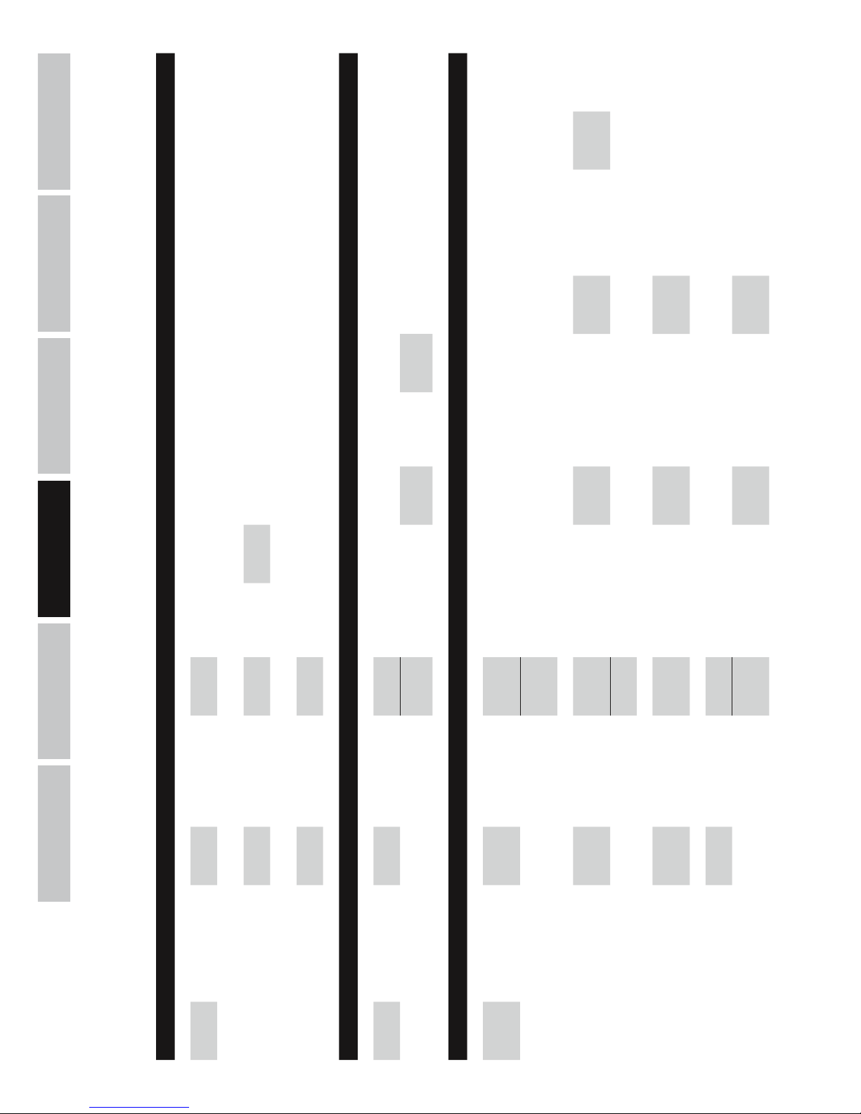
38
DEUTSCHFRANCAIS
ESPAÑOL
ENGLISH
ITALIANO POLSKI
Display: Display: Display: Display:
Program
Utilities
-> ENTER ->
<- ESC
NAV/PM1
Recall a
Program
-> ENTER ->
<- ESC
PM2/3 01 - 24
-> 2x ENTER <-
<- ESC
Save a
Program
-> ENTER ->
<- ESC
PM2/3 01 - 24
-> ENTER ->
<- ESC
Set Program
Name
NAV/PM1
PM2/3
-> 2x ENTER <-
<- ESC
Delete a
Program
-> ENTER ->
<- ESC
PM2/3 01 - 24
-> 2x ENTER <-
<- ESC
Display: Display: Display: Display: Display:
Interface
Utilities
-> ENTER ->
<- ESC
Interface
Setup
-> ENTER ->
<- ESC
PM2/3 Source : USB
-> ENTER
<- ESC
Source :
RS485
-> ENTER ->
<- ESC
NAV/PM1
Remote ID
Num = xx
PM2/3
Remote ID
Num = 01
- 32
-> ENTER
<- ESC
Display: Display: Display: Display: Display: Display:
Security
Utilities
-> ENTER ->
<- ESC
NAV/PM1
Show
Parameter
-> ENTER ->
<- ESC
PM2/3
Parameter
will be
shown
-> ENTER <-
Parameter
will not be
shown
-> ENTER <-
Lock Unit
-> ENTER ->
<- ESC
PM2/3 Lock : On
-> ENTER ->
<- ESC
Main Menu
(Menu
locked)
(to unlock)
UTILITY ->
Lock Unit -> ENTER -> PM2/3 Lock : Off -> ENTER <-
Lock : Off -> ENTER <-
User
Password
-> ENTER ->
<- ESC
NAV/PM1
PM2/3
User
Password
[000000]
-> ENTER ->
<- ESC
NAV/PM1
PM2/3
New
Password
[xxxxxx]
-> ENTER ->
<- ESC
NAV/PM1
PM2/3
Confirm
Password
[xxxxxx]
-> ENTER <-
Enable
Password
-> ENTER ->
<- ESC
PM2/3
Password :
Disable
-> ENTER
Password :
Enable
-> ENTER ->
Main Menu
(Menu
locked)
(to unlock)
UTILITY ->
User
Password
[xxxxxx]
-> ENTER <-
MENÚ PROGRAM UTILITIES, INTERFACE UTILITIES Y SECURITY UTILITIES
Page 39
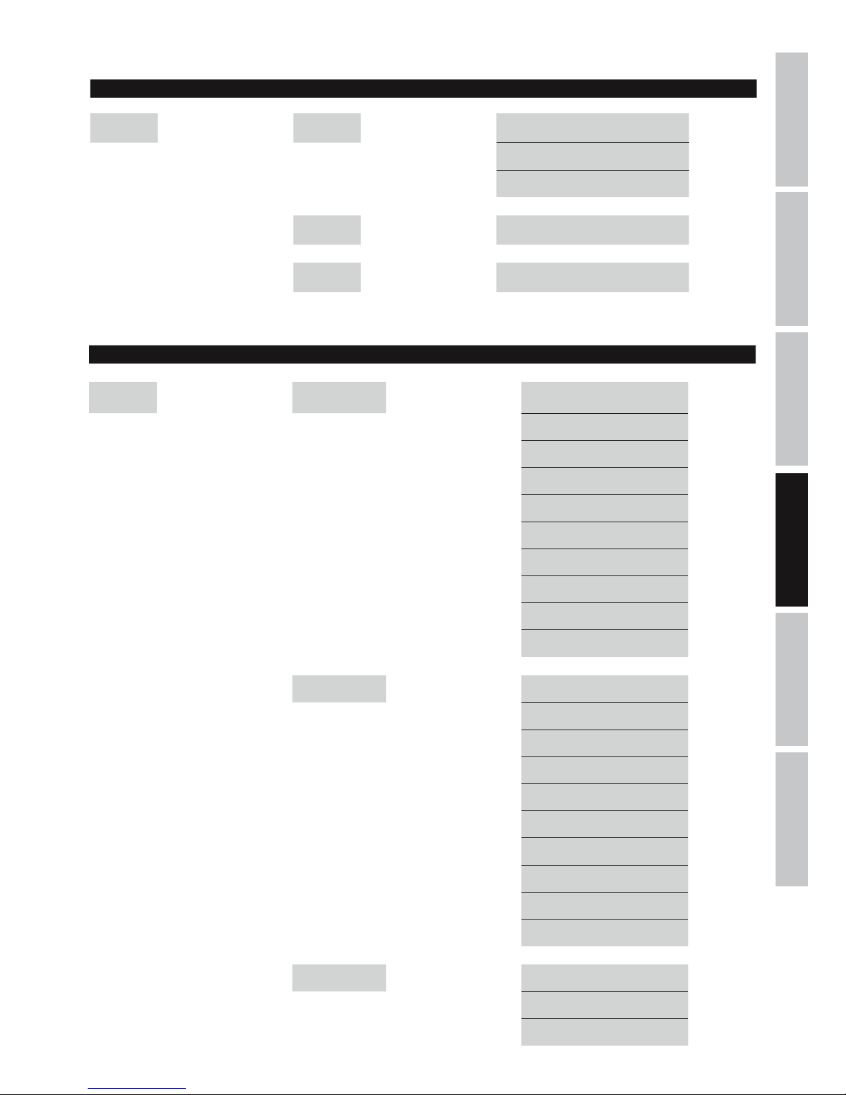
ITALIANOPOLSKIESPAÑOL
FRANCAISDEUTSCHENGLISH
39
MENÚ INPUTS A/B
MENÚ OUTPUTS 1-6
Display: Display:
EDIT OUTPUT
1-6:
-> EDIT
1-6 ->
NAV/PM1 Out 1-6 HPF -> ENTER -> PM2 KHz <- ESC
PM3 No Cut-Off <- ESC
Butwrth 6 dB <- ESC
Butwrth 12 dB <- ESC
Lnk/Ril 12 dB <- ESC
Bessel 12 dB <- ESC
Butwrth 18 dB <- ESC
Butwrth 24 dB <- ESC
Lnk/Ril 24 dB <- ESC
Bessel 24 dB <- ESC
Out 1-6 LPF -> ENTER -> PM2 KHz <- ESC
PM3 No Cut-Off <- ESC
Butwrth 6 dB <- ESC
Butwrth 12 dB <- ESC
Lnk/Ril 12 dB <- ESC
Bessel 12 dB <- ESC
Butwrth 18 dB <- ESC
Butwrth 24 dB <- ESC
Lnk/Ril 24 dB <- ESC
Bessel 24 dB <- ESC
Out 1-6 EQ1-EQ7 -> ENTER -> NAV/PM1 KHz <- ESC
PM2 BW <- ESC
PM3 dB <- ESC
Display: Display:
EDIT INPUT
A/B:
-> EDIT
A/B ->
NAV/PM1
Input-A/B
EQ1-EQ5
-> ENTER -> NAV/PM1 KHz <- ESC
PM2 BW <- ESC
PM3 dB <- ESC
Input-A/B
Gain
-> ENTER -> PM2/3 dB <- ESC
Input-A/B
Delay
-> ENTER -> PM2/3
m/ms
(0 m...288,65932 m / 0 ms...848,998 ms)
<- ESC
Page 40
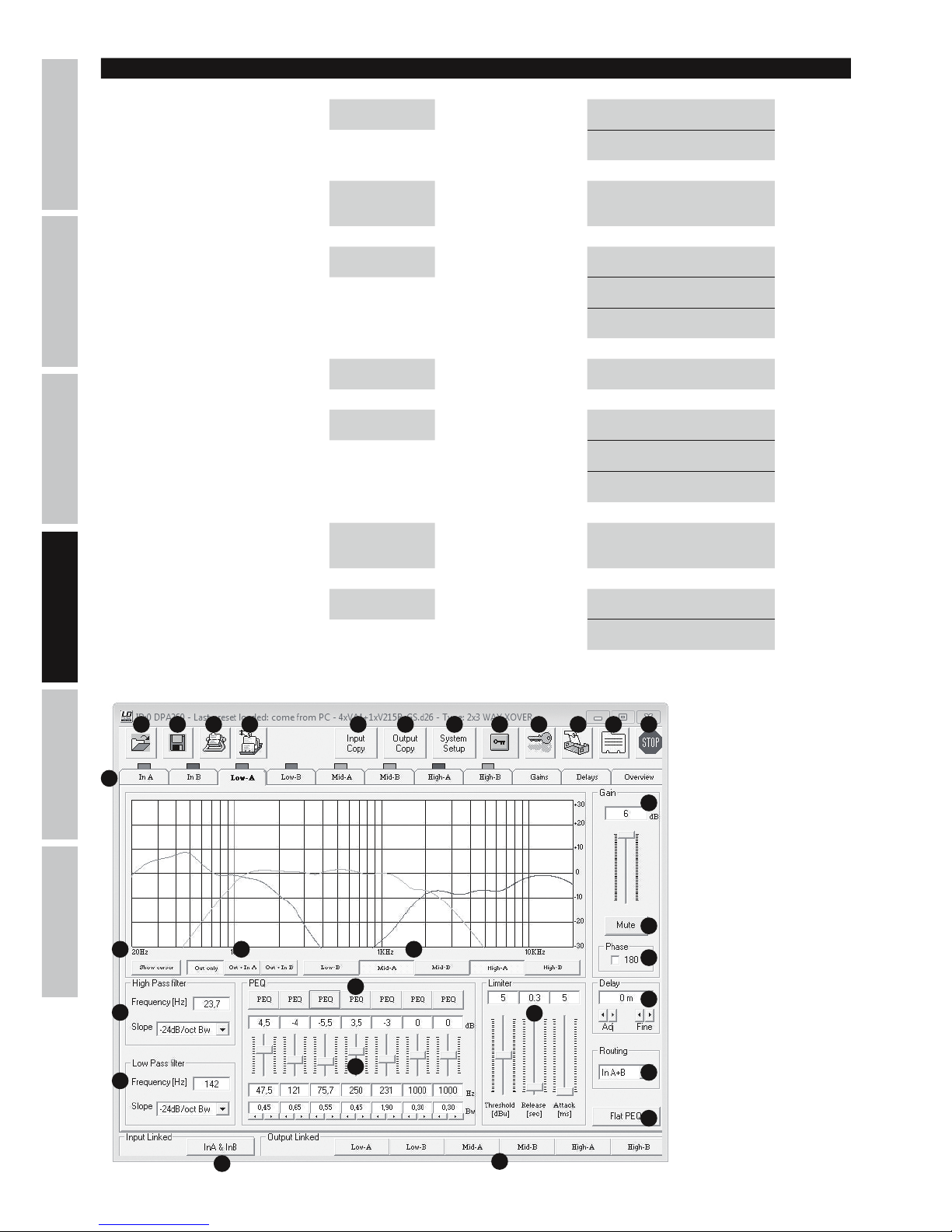
40
DEUTSCHFRANCAIS
ESPAÑOL
ENGLISH
ITALIANO POLSKI
SOFTWARE LDDPA260 (CAPTURA DE EJEMPLO)
1 2 3 4 5 6 7 109 11 12
13
1415 16
17
18
19
20
8
21
25
22
24
23
26
27
28
29
Out 1-6 Vu-Meter -> ENTER -> PM2/3 Level <- ESC
Limiter Act <- ESC
Out 1-6 Name -> ENTER ->
NAV/PM1
PM2/3
Name = xxxxxx -> ENTER <-
Out 1-6 Source -> ENTER -> PM2/3 InA <- ESC
InB <- ESC
InA+InB <- ESC
Out 1-6 Gain -> ENTER -> PM2/3 dB <- ESC
Out 1-6 Limiter -> ENTER -> NAV/PM1 Attack ms <- ESC
PM2 Release s <- ESC
PM3 dBu <- ESC
Out 1-6 Delay -> ENTER -> PM2/3
m/ms
(0 m...288,65932 m /
0 ms...848,998 ms)
<- ESC
Out 1-6 Polarity -> ENTER -> PM2/3 Normal <- ESC
Invert <- ESC
Display: Display:
Page 41

ITALIANOPOLSKIESPAÑOL
FRANCAISDEUTSCHENGLISH
41
SOFTWARE DPA260
NOTA: Al conectar el procesador DPA260 con un PC/software por USB o RS-485, todos los controles del frontal del procesador
quedarán bloqueados.
1. Abrir un preajuste del procesador guardado en disco.
2. Guardar en disco los preajustes cambiados y nuevos del procesador.
3. Almacenar un preajuste en el procesador DPA260. Se pueden almacenar hasta 24preajustes de procesador en un DPA260.
4. Leer preajuste del procesador DPA260
5. Copiar la configuración de un canal de entrada a otro.
6. Copiar la configuración de un canal de salida a otro.
7. Configurar la función crossover del procesador DPA260 (2x2 WAY XOVER + SUB, 2x3 WAY XOVER, 6 WAY XOVER)
8. Bloquear los canales de salida en la aplicación de software. Si se activa esta función de bloqueo, solo podrá hacer cambios en los
canales de entrada (por software).
9. Bloquear el procesador DPA260 (contraseña de 6dígitos). El procesador permanecerá bloqueado incluso después de cerrar la aplicación
de software y desconectarse del PC y sólo se puede desbloquear mediante la aplicación de software o la función de desbloqueo dentro del
procesador DPA260.
10. Cambiar el nombre del procesador DPA260.
11. Cambiar el nombre de los canales de entrada y salida.
12. Desconectar el software del procesador DPA260.
13. Acceder a los diferentes canales de entrada y salida, ajustes de ganancia y retardo y el diagrama general del sistema.
14. Gráfica de los ajustes de ecualización del canal seleccionado.
15. Mostrar el cursor en el ecualizador del canal seleccionado.
16. Permite seleccionar si los ajustes del ecualizador gráfico se aplican solo a los canales de salida o a los canales de entrada y de salida.
17. Ajustar y mostrar la ganancia del canal seleccionado.
18. Silenciar el canal seleccionado.
19. Invertir la polaridad del canal seleccionado.
20. Ajustar el retardo del canal seleccionado (0 ms, 0,02 ms...848,998 ms / 0 m, 0,0068 m...288,65932 m).
21. Seleccionar la fuente de entrada para el canal seleccionado.
22. Configurar el filtro paso altos del canal seleccionado.
23. Configurar el filtro paso bajos del canal seleccionado.
24. Ecualizador de 7bandas para el canal de salida seleccionado (los canales de entrada tienen un ecualizador de 5bandas).
25. Ajustar la curva del ecualizador.
26. Restablecer el ecualizador del canal seleccionado.
27. Ajustar el limitador del canal seleccionado.
28. Botón para vincular los dos canales de entrada.
29. Botones para vincular los canales de salida.
ESPECIFICACIONES
Nombre del modelo: LDDPA260
Tipo de producto: Controlador DSP
Tipo: Digital
Configuración: 6 canales
Conversor AD/DA: 24 bits
Frecuencia de muestreo: 48 kHz
Respuesta en frecuencia: 20 a 20.000 Hz
Tipo de filtro: Butterworth, Bessel, Linkwitz-Riley
Pendiente del filtro: 6, 12, 18, 24 dB/octava
Delay (canales de entrada y salida): 0 ms, 0,02 ms...848,998 ms / 0 m, 0,0068 m...288,65932 m
Margen dinámico: 111 dB (ponderación A)
Relación señal/ruido: > 106 dB
Distorsión armónica (THD): < 0,005%
Rechazo del modo común: 107 dB (+20 dBu a 1 kHz)
Page 42
42
DEUTSCHFRANCAIS
ESPAÑOL
ENGLISH
ITALIANO POLSKI
Máximo nivel de entrada: +20 dBu (balanceado)
Nivel máximo de salida: +20 dBu (balanceado)
Impedancia de entrada: 27 Kohmios
Impedancia de salida: 120 ohmios
Controles: Nav/PM1, PM2, PM3, Enter, Esc, Utility
Edit Input A - B, Edit Output 1 - 6
Indicadores: Pantalla LCD multifunción, 2vúmetros de entrada (6segmentos ), 2LEDs CLIP de recorte de entra-
da, 2LEDs EDIT de Edición de entrada, 2LEDs MUTE de silenciamiento de entrada, 6vúmetros de
salida (5segmentos),
6LEDs CLIP de recorte de salida, 6LEDs LIMIT de limitación de salida, 6LEDs Edit de Edición de
salida, 6LEDs MUTE de silenciamiento de salida
Entradas de línea: 3 (2 analógicas, 1 digital estéreo)
Conectores de entrada de línea: XLR (balanceado), S/PDIF (RCA)
Salidas de línea: 6
Conectores de salida de línea: XLR (balanceado)
Interfaces: USB, RS-485 (entrada y salida)
Toma eléctrica: Conector IEC
Alimentación eléctrica: 90 a 250 VAC
Consumo: 14 W
Fusible: T800mAL/250V
Dimensiones (An x Al x F): 482x44,5x225 mm
DECLARACIÓN DEL FABRICANTE
GARANTÍA DEL FABRICANTE Y LIMITACIÓN DE RESPONSABILIDAD
Consulte nuestras condiciones de garantía y limitaciones de responsabilidad en: http://www.adamhall.com/media/shop/downloads/documents/manufacturersdeclarations.pdf. En caso de necesitar servicio técnico, póngase en contacto con Adam Hall GmbH, Daimlerstraße 9,
61267 Neu Anspach (Alemania); correo electrónico [email protected]; +49 (0)6081 / 9419-0.
ELIMINACIÓN CORRECTA DE ESTE PRODUCTO
(Aplicable en la Unión Europea y en los países europeos que dispongan de un sistema de recogida selectiva) El símbolo que aparece
sobre el producto o en la documentación adjunta indica que al final de la vida útil del equipo, no deberá desecharlo con los demás
residuos domésticos, con el fin de evitar posibles efectos negativos en el medio ambiente y en la salud humana debidos al vertido
incontrolado de desechos. La recogida selectiva ayuda a su posterior reciclaje y fomenta la reutilización sostenible de los componentes de
este equipo. Si es un particular, póngase en contacto con el distribuidor donde adquirió este producto, o con el ayuntamiento, para
informarse sobre el reciclaje adecuado de este equipo. Si es una empresa, póngase en contacto con su proveedor para informarse sobre los
términos y condiciones de su contrato de compra-venta. Este producto no debe mezclarse con otros residuos industriales.
Conformidad CE
Adam Hall GmbH declara por la presente que este producto es conforme con las siguientes directivas (según sea aplicable):
R&TTE (1999/5/CE) o RED (2014/53/UE) a partir de junio de 2017
Directiva de baja tensión (2014/35/UE)
Directiva EMC (2014/30/UE)
RoHS (2011/65/UE)
Puede consultar la declaración de conformidad completa en www.adamhall.com.
También puede solicitarla a [email protected].
Page 43
ITALIANOPOLSKIESPAÑOL
FRANCAISDEUTSCHENGLISH
43
POLSKI
GRATULUJEMY WYBORU!
To urządzenie zostało zaprojektowane i wyprodukowane przy zastosowaniu najwyższych kryteriów jakościowych w celu zapewnienia wieloletniej bezawaryjnej eksploatacji. Firma LD Systems gwarantuje to swoją marką i wieloletnim doświadczeniem w wytwarzaniu wysokiej
jakości produktów audio. Proszę starannie przeczytać niniejszą instrukcję obsługi, aby móc jak najszybciej zacząć użytkować ten produkt
marki LD Systems.
Dalsze informacje na temat firmy LD SYSTEMS dostępne są na naszej stronie internetowej WWW.LD-SYSTEMS.COM
ŚRODKI OSTROŻNOŚCI
1. Należy dokładnie przeczytać niniejszą instrukcję.
2. Wszystkie informacje i instrukcje przechowywać w bezpiecznym miejscu.
3. Należy przestrzegać zaleceń.
4. Należy przestrzegać wszystkich wskazówek ostrzegawczych. Nie wolno usuwać wskazówek bezpieczeństwa ani innych informacji
znajdujących się na urządzeniu.
5. Używać urządzenia wyłącznie w sposób zgodny z jego przeznaczeniem.
6. Stosować wyłącznie stabilne i pasujące statywy, ew. elementy mocujące (w przypadku instalacji stałych). Należy zadbać o prawidłową instalację
uchwytów ściennych i ich odpowiednie zabezpieczenie. Zapewnić bezpieczną instalację urządzenia i upewnić się, że urządzenie nie spadnie.
7. Podczas instalacji przestrzegać obowiązujących w danym kraju przepisów bezpieczeństwa.
8. Urządzenie instalować i eksploatować z dala od grzejników, zasobników ciepła, pieców i innych źródeł ciepła. Zadbać o zainstalowanie urządzenia w
taki sposób, aby zawsze było ono wystarczająco chłodzone i nie mogło ulec przegrzaniu.
9. Nie umieszczać na urządzeniu źródeł zapłonu, takich jak np. palące się świece.
10. Nie wolno blokować szczelin wentylacyjnych. Unikać bezpośredniego działania promieni słonecznych!
11. Nie używać urządzenia w bezpośrednim sąsiedztwie wody (nie dotyczy specjalnych urządzeń do stosowania na zewnątrz – w takim
przypadku należy przestrzegać podanych poniżej wskazówek specjalnych). Urządzenie nie może mieć kontaktu z palnymi materiałami,
płynami ani gazami.
12. Zabezpieczyć urządzenie przed wniknięciem kapiącej lub pryskającej wody. Nie wolno stawiać na urządzeniu pojemników napełnionych
płynami, takich jak wazony czy naczynia z piciem.
13. Należy zadbać o to, aby do urządzenia nie wpadały żadne przedmioty.
14. Urządzenie można eksploatować tylko przy użyciu akcesoriów zalecanych i przewidzianych przez producenta.
15. Nie otwierać urządzenia ani nie dokonywać w nim zmian.
16. Po podłączeniu urządzenia sprawdzić wszystkie ciągi kablowe, aby zapobiec szkodom lub wypadkom np. w wyniku potknięcia.
17. Podczas transportu zadbać o to, aby urządzenie nie upadło, gdyż może to spowodować uszkodzenie mienia i obrażenia ciała.
18. Jeśli urządzenie nie działa prawidłowo, do jego wnętrza dostały się płyny lub przedmioty lub jeśli urządzenie zostało uszkodzone w inny
sposób, należy je natychmiast wyłączyć i odłączyć od gniazda sieciowego (jeśli urządzenie jest aktywne). Naprawę takiego urządzenia może
wykonać tylko autoryzowany personel specjalistyczny.
19. Do czyszczenia urządzenia stosować suchą ściereczkę.
20. Przestrzegać obowiązujących w danym kraju przepisów dotyczących usuwania odpadów. Podczas utylizacji opakowania oddzielić
tworzywo sztuczne od papieru i tektury.
21. Worki z tworzywa sztucznego należy przechowywać w miejscu niedostępnym dla dzieci.
DOTYCZY URZĄDZEŃ Z ZASILANIEM SIECIOWYM
22. UWAGA: jeśli kabel sieciowy urządzenia jest wyposażony w zestyk ochronny, należy go podłączyć do gniazda z przewodem uziemiającym. Nigdy nie wolno dezaktywować przewodu uziemiającego kabla sieciowego.
23. Nie włączać urządzenia bezpośrednio po narażeniu go na silne wahania temperatury (np. po transporcie). Wilgoć i skropliny mogą uszkodzić
urządzenie. Włączyć urządzenie dopiero wtedy, gdy osiągnie temperaturę pokojową.
24. Przed podłączeniem urządzenia do gniazda elektrycznego należy sprawdzić, czy napięcie i częstotliwość sieci elektrycznej odpowiada wartościom podanym na urządzeniu. Jeśli urządzenie jest wyposażone w przełącznik napięcia, należy podłączyć je do gniazda tylko
wówczas, gdy wartości urządzenia odpowiadają wartościom sieci elektrycznej. Jeśli dołączony kabel sieciowy lub dołączony adapter
sieciowy nie pasuje do gniazda elektrycznego, należy skontaktować się z elektrykiem.
25. Nie stawać na kablu sieciowym. Należy zadbać o to, aby kable przewodzące napięcie nie były zagięte przy gnieździe sieciowym, przy
adapterze sieciowym ani przy gnieździe urządzenia.
26. Przy podłączaniu urządzenia zawsze należy zadbać o to, aby kabel sieciowy lub adapter sieciowy był zawsze łatwo dostępny. Odłączyć
urządzenie od źródła zasilania, gdy nie jest ono używane lub gdy ma zostać poddane czyszczeniu. Zawsze należy wyjmować kabel sieciowy
i adapter sieciowy z gniazda, chwytając za wtyczkę lub adapter, a nie za kabel. Nigdy nie dotykać kabla sieciowego i adaptera sieciowego
mokrymi dłońmi.
9. W miarę możliwości nie włączać i wyłączać urządzenia w krótkich odstępach czasu, gdyż może to mieć negatywny wpływ na jego żywotność.
28. WAŻNA INFORMACJA: bezpieczniki należy wymieniać wyłącznie na bezpieczniki tego samego typu i o takich samych wartościach. Jeśli bezpiecznik
stale się przepala, należy skontaktować się z autoryzowanym centrum serwisowym.
29. Aby całkowicie odłączyć urządzenie od sieci, należy wyjąć kabel sieciowy lub adapter sieciowy z gniazda.
30. Jeśli urządzenie jest wyposażone w przyłącze sieciowe Volex, konieczne jest odblokowanie odpowiedniej wtyczki urządzenia Volex, zanim
będzie możliwe jej odłączenie. Oznacza to także, iż w wyniku pociągnięcia za kabel urządzenie może się przesunąć i spaść, co może spowodować
obrażenia ciała i/lub inne szkody, dlatego ważne jest, aby przewody były odpowiednio poprowadzone.
31. W przypadku zagrożenia uderzeniem pioruna lub jeśli urządzenie przez dłuższy czas nie jest używane, należy wyjąć kabel sieciowy i
adapter sieciowy z gniazda.
Page 44
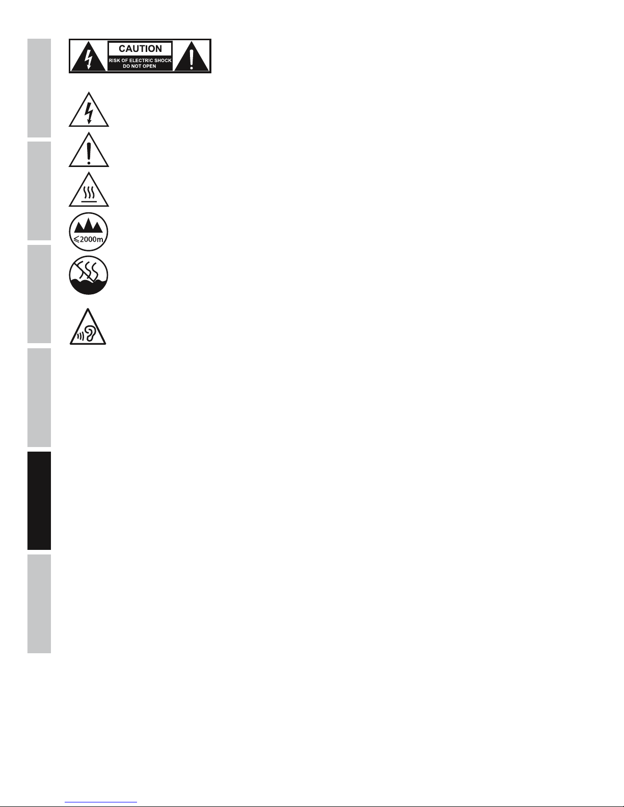
44
DEUTSCHFRANCAIS
ESPAÑOL
ENGLISH
ITALIANO POLSKI
UWAGA:
Nigdy nie zdejmować pokrywy, gdyż grozi to porażeniem prądem. We wnętrzu urządzenia nie ma
żadnych części, które mogłyby zostać naprawione bądź poddane czynnościom konserwacyjnym przez
użytkownika. Czynności konserwacyjne i naprawy może przeprowadzać wyłącznie wykwalifikowany
personel serwisowy.
Trójkąt równoboczny z symbolem błyskawicy sygnalizuje nieizolowane, niebezpieczne napięcie we wnętrzu urządzenia, które
może spowodować porażenie prądem.
Trójkąt równoboczny z wykrzyknikiem oznacza ważne wskazówki dotyczące obsługi i konserwacji.
Ostrzeżenie! Ten symbol ostrzega przed gorącymi powierzchniami. Podczas użytkowania niektóre elementy mogą się nagrzać.
Urządzenie można dotykać lub transportować dopiero po jego ostygnięciu (po odczekaniu co najmniej 10 minut).
Ostrzeżenie! To urządzenie przeznaczone jest do użytku do maksymalnej wysokości 2000 m n.p.m.
Ostrzeżenie! To urządzenie nie jest przewidziane do użytku w tropikalnych strefach klimatycznych.
Aby zapobiec ewentualnemu uszkodzeniu słuchu, unikać słuchania przy dużym poziomie głośności przez dłuższy czas.
Głośny dźwięk może prowadzić do uszkodzenia słuchu nawet przy krótkim okresie oddziaływania. Głośność należy zawsze
utrzymywać na przyjemnym dla ucha poziomie.
UWAGA! WYSOKI POZIOM GŁOŚNOŚCI PRODUKTÓW AUDIO!
To urządzenie przewidziane jest do zastosowań profesjonalnych. Komercyjne stosowanie tego urządzenia podlega obowiązującym w danym
kraju przepisom i wytycznym dotyczącym zapobiegania wypadkom. Firma Adam Hall jest jako producent zobowiązana do wyraźnego
informowania o potencjalnym zagrożeniu dla zdrowia. Utrata słuchu w wyniku wysokiego poziomu głośności i długotrwałego narażenia: podczas stosowania tego produktu może powstać wysoki poziom ciśnienia akustycznego (SPL), który może doprowadzić do nieodwracalnego
uszkodzenia słuchu u artystów, pracowników i widzów. Należy unikać długotrwałego narażenia na wysoki poziom głośności powyżej 90 dB.
Page 45
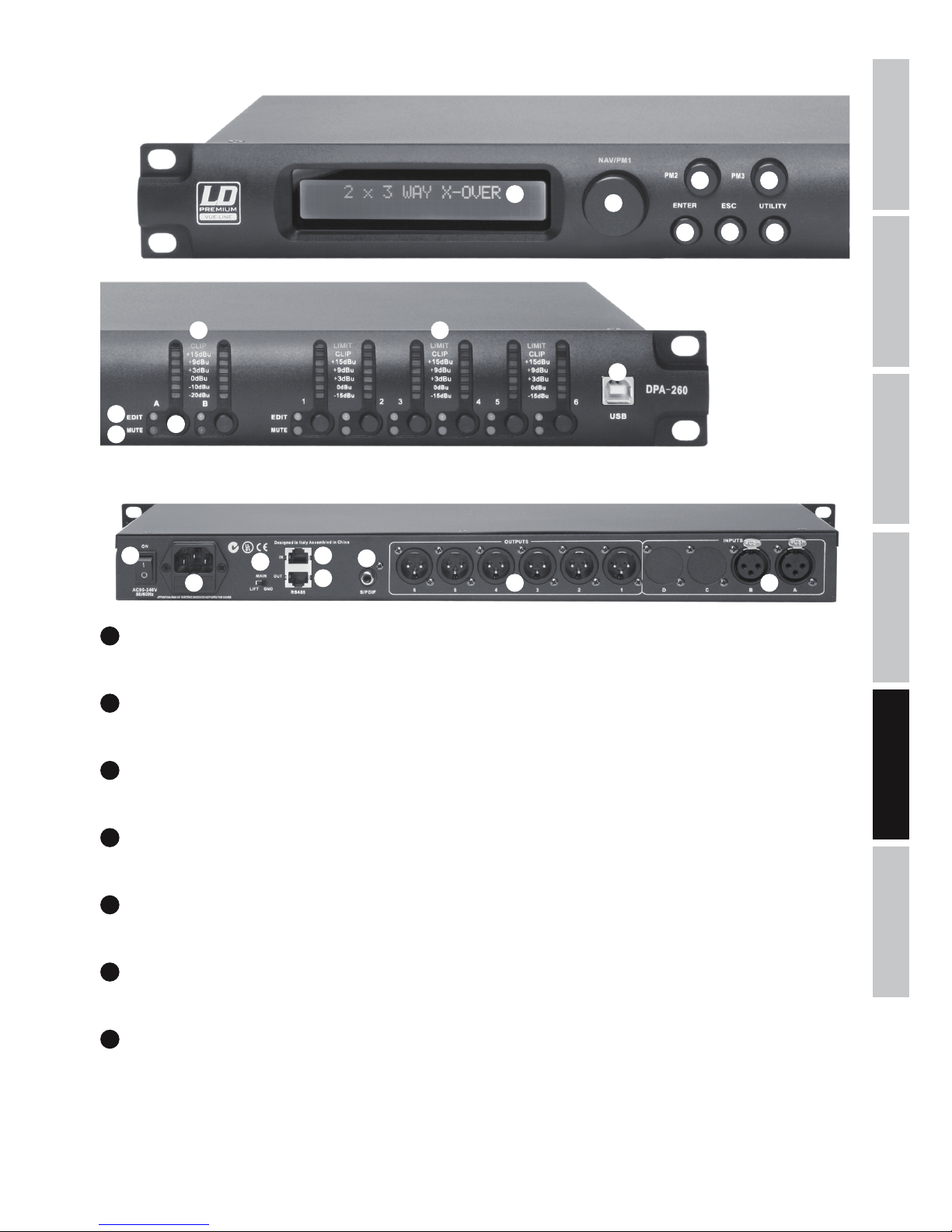
ITALIANOPOLSKIESPAÑOL
FRANCAISDEUTSCHENGLISH
45
PRZYŁĄCZA, ELEMENTY OBSŁUGI I WSKAŹNIKI
1
2
3
4
5
6 7
9
12
13
14
15
16
17
18
19
20 21
8
10
11
1
DISPLAY
Podświetlany, wielofunkcyjny wyświetlacz LCD 2 x 24 znaki
2
UTILITY
Aby dokonać ustawień w menu urządzenia, nacisnąć przycisk UTILITY.
3
NAV/PM1
Po naciśnięciu przycisku UTILITY można za pomocą pokrętła NAV/PM1 przechodzić między punktami menu w menu głównym lub w podmenu.
4
ENTER
Aby przejść o jeden poziom niżej w strukturze menu i potwierdzić zmiany parametrów, nacisnąć przycisk ENTER.
5
ESC
Aby przejść o jeden poziom wyżej w strukturze menu i powrócić do głównego widoku wyświetlacza, nacisnąć przycisk ESC.
6
PM2
Za pomocą pokrętła PM2 można zmienić parametry wybranego punktu menu. Potwierdzić ustawienie za pomocą przycisku ENTER.
7
PM3
Za pomocą pokrętła PM3 można zmienić parametry wybranego punktu menu. Potwierdzić ustawienie za pomocą przycisku ENTER.
Page 46
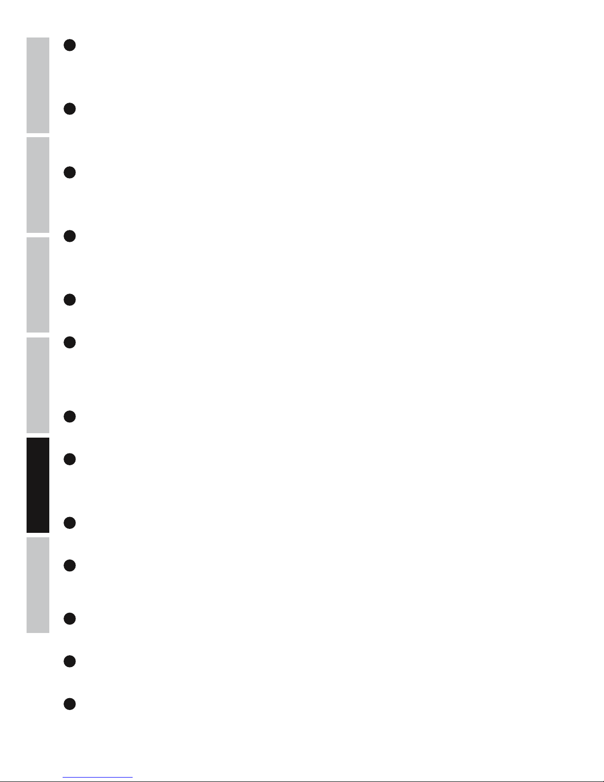
46
DEUTSCHFRANCAIS
ESPAÑOL
ENGLISH
ITALIANO POLSKI
8
INPUT METER A / B
7-segmentowy sygnalizator poziomu LED dla kanałów wejściowych A i B. Gdy zaświeci się czerwona dioda CLIP LED na górnym końcu
sygnalizatora poziomu, należy zredukować poziom wyjściowy urządzenia zewnętrznego (np. pulpitu mikserskiego), aby uniknąć zniekształceń
(maksymalnie +20 dBu).
9
OUTPUT METER 1 - 6
7-segmentowy wskaźnik poziomu LED dla kanałów wyjściowych od 1 do 6. Aby uniknąć zniekształceń, należy zredukować poziom wyjściowy
odpowiedniego kanału wyjściowego, gdy zaświeci się czerwona dioda CLIP LED. Żółta dioda LIMIT LED świeci się, gdy sygnał wyjściowy
odpowiedniego kanału zostanie ograniczony przez zintegrowany limiter (należy dostosować ustawienia limitera do elementów systemu).
10
EDIT-LED
Krótko nacisnąć przycisk nr 12 wybranego kanału wejściowego lub wyjściowego, aby przejść do trybu edycji kanału. Zaświeci się niebieska
dioda EDIT LED wybranego kanału. Aby opuścić tryb edycji danego kanału, ponownie krótko nacisnąć przycisk nr 12. Niebieska dioda EDIT
LED zgaśnie.
11
MUTE-LED
Nacisnąć przycisk nr 12 wybranego kanału wejściowego lub wyjściowego i przytrzymać go przez ok. 2 sekundy, aby wyciszyć kanał.
Zaświeci się czerwona dioda MUTE LED wybranego kanału. Aby zakończyć wyciszenie danego kanału, ponownie nacisnąć przycisk nr 12 i
przytrzymać go przez ok. 2 sekundy. Sygnał audio jest ponownie nadawany, a czerwona dioda MUTE LED przestaje się świecić.
12
PRZYCISKI FUNKCYJNE INPUT A/B ORAZ OUTPUT 1–6
Nacisnąć przycisk, aby wywołać funkcje opisane w punktach 10 i 11.
13
USB-PORT
Port USB służy do wygodnej edycji i zarządzania wszystkimi funkcjami lub ustawieniami kontrolera DSP LDDPA260 za pośrednictwem
komputera z systemem Windows. Oprogramowanie i sterowniki do systemów operacyjnych Windows są dołączone do urządzenia. Istnieje
także możliwość pobrania ich, a także ustawień wstępnych, z naszej strony internetowej WWW.LD-SYSTEMS.COM oferującej pakiety do
wielu głośników LD Systems.
14
ON
Włącznik/Wyłącznik dopływu zasilania do urządzenia.
15
GNIAZDO SIECIOWE IEC ZE ZINTEGROWANĄ PODSTAWĄ BEZPIECZNIKA
Służy do zasilania urządzenia. W zestawie znajduje się odpowiedni kabel sieciowy. WAŻNE WSKAZÓWKI: bezpiecznik należy wymieniać
wyłącznie na bezpiecznik tego samego typu i o takich samych parametrach (T800 mAL/250 V)! Jeśli bezpiecznik stale się przepala, należy
skontaktować się z autoryzowanym centrum serwisowym.
16
GROUND LIFT
Włącznik ten może zapobiec powstawaniu przydźwięków, gdy zostaną podłączone urządzenia z różnym potencjałem uziemienia.
17
RS485 IN
Po podłączeniu za pomocą złącza USB do adaptera RS485 LDDPA260RC interfejs ten umożliwia zdalne sterowanie urządzeniem LDDPA260
poprzez standardowe, wielożyłowe złącze XLR za pomocą komputera z systemem Windows na stanowisku mikserskim.
18
RS485 OUT
Służy do przesyłania sygnału sterowania do jednego lub kilku dodatkowych kontrolerów DSP LDDPA260.
19
S/PDIF
Cyfrowe wejście stereo w formacie współosiowym S/PDIF.
20
OUTPUTS 1 - 6
Symetryczne wyjścia audio z męskimi 3-stykowymi gniazdami XLR.
Page 47
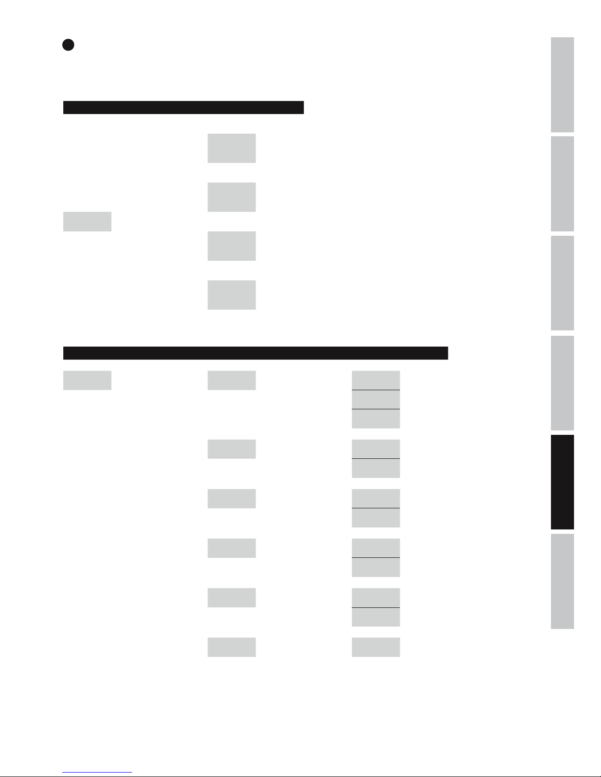
ITALIANOPOLSKIESPAÑOL
FRANCAISDEUTSCHENGLISH
47
STRUKTURA MENU – MENU NARZĘDZI
Display: Display:
System Utilities
-> ENTER ->
<- ESC
Program Utilities
-> ENTER ->
<- ESC
Main Menu UTILITY NAV/PM1
Interface
Utilities
-> ENTER ->
<- ESC
Security Utilities
-> ENTER ->
<- ESC
STRUKTURA MENU – NARZĘDZIA SYSTEMU
Display: Display: Display:
System Utilities
-> ENTER ->
<- ESC
NAV/PM1 System Setup
-> ENTER ->
<- ESC
PM2/3 2x2 WAY + SUB -> ENTER <-
2x3 WAY XOVER -> ENTER <-
6 WAY XOVER -> ENTER <-
Input Routing
-> ENTER ->
<- ESC
PM2/3 Source : Analog -> ENTER <-
Source : Digital -> ENTER <-
Power-On
Procedure
-> ENTER ->
<- ESC
PM2/3 Fade-In : On -> ENTER <-
Fade-In : Off -> ENTER <-
Delay Units
-> ENTER ->
<- ESC
PM2/3
Unit : Distan-
ce(m)
-> ENTER <-
Unit : Time(ms) -> ENTER <-
Ramps on
changes
-> ENTER ->
<- ESC
PM2/3 Ramps : On -> ENTER <-
Ramps : Off -> ENTER <-
Software
Version
-> ENTER ->
<- ESC
Version : V1.xx <- ESC
21
INPUTS A + B
Symetryczne wejścia audio z żeńskimi 3-stykowymi gniazdami XLR.
Page 48
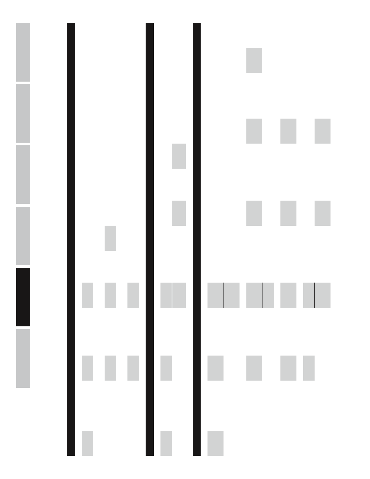
48
DEUTSCHFRANCAIS
ESPAÑOL
ENGLISH
ITALIANO POLSKI
Display: Display: Display: Display:
Program
Utilities
-> ENTER ->
<- ESC
NAV/PM1
Recall a
Program
-> ENTER ->
<- ESC
PM2/3 01 - 24
-> 2x ENTER <-
<- ESC
Save a
Program
-> ENTER ->
<- ESC
PM2/3 01 - 24
-> ENTER ->
<- ESC
Set Program
Name
NAV/PM1
PM2/3
-> 2x ENTER <-
<- ESC
Delete a
Program
-> ENTER ->
<- ESC
PM2/3 01 - 24
-> 2x ENTER <-
<- ESC
Display: Display: Display: Display: Display:
Interface
Utilities
-> ENTER ->
<- ESC
Interface
Setup
-> ENTER ->
<- ESC
PM2/3 Source : USB
-> ENTER
<- ESC
Source :
RS485
-> ENTER ->
<- ESC
NAV/PM1
Remote ID
Num = xx
PM2/3
Remote ID
Num = 01
- 32
-> ENTER
<- ESC
Display: Display: Display: Display: Display: Display:
Security
Utilities
-> ENTER ->
<- ESC
NAV/PM1
Show
Parameter
-> ENTER ->
<- ESC
PM2/3
Parameter
will be
shown
-> ENTER <-
Parameter
will not be
shown
-> ENTER <-
Lock Unit
-> ENTER ->
<- ESC
PM2/3 Lock : On
-> ENTER ->
<- ESC
Main Menu
(Menu
locked)
(to unlock)
UTILITY ->
Lock Unit -> ENTER -> PM2/3 Lock : Off -> ENTER <-
Lock : Off -> ENTER <-
User
Password
-> ENTER ->
<- ESC
NAV/PM1
PM2/3
User
Password
[000000]
-> ENTER ->
<- ESC
NAV/PM1
PM2/3
New
Password
[xxxxxx]
-> ENTER ->
<- ESC
NAV/PM1
PM2/3
Confirm
Password
[xxxxxx]
-> ENTER <-
Enable
Password
-> ENTER ->
<- ESC
PM2/3
Password :
Disable
-> ENTER
Password :
Enable
-> ENTER ->
Main Menu
(Menu
locked)
(to unlock)
UTILITY ->
User
Password
[xxxxxx]
-> ENTER <-
STRUKTURA MENU – NARZĘDZIA PROGRAMOWE, NARZĘDZIA INTERFEJSU, NARZĘDZIA ZABEZPIECZEŃ
Page 49
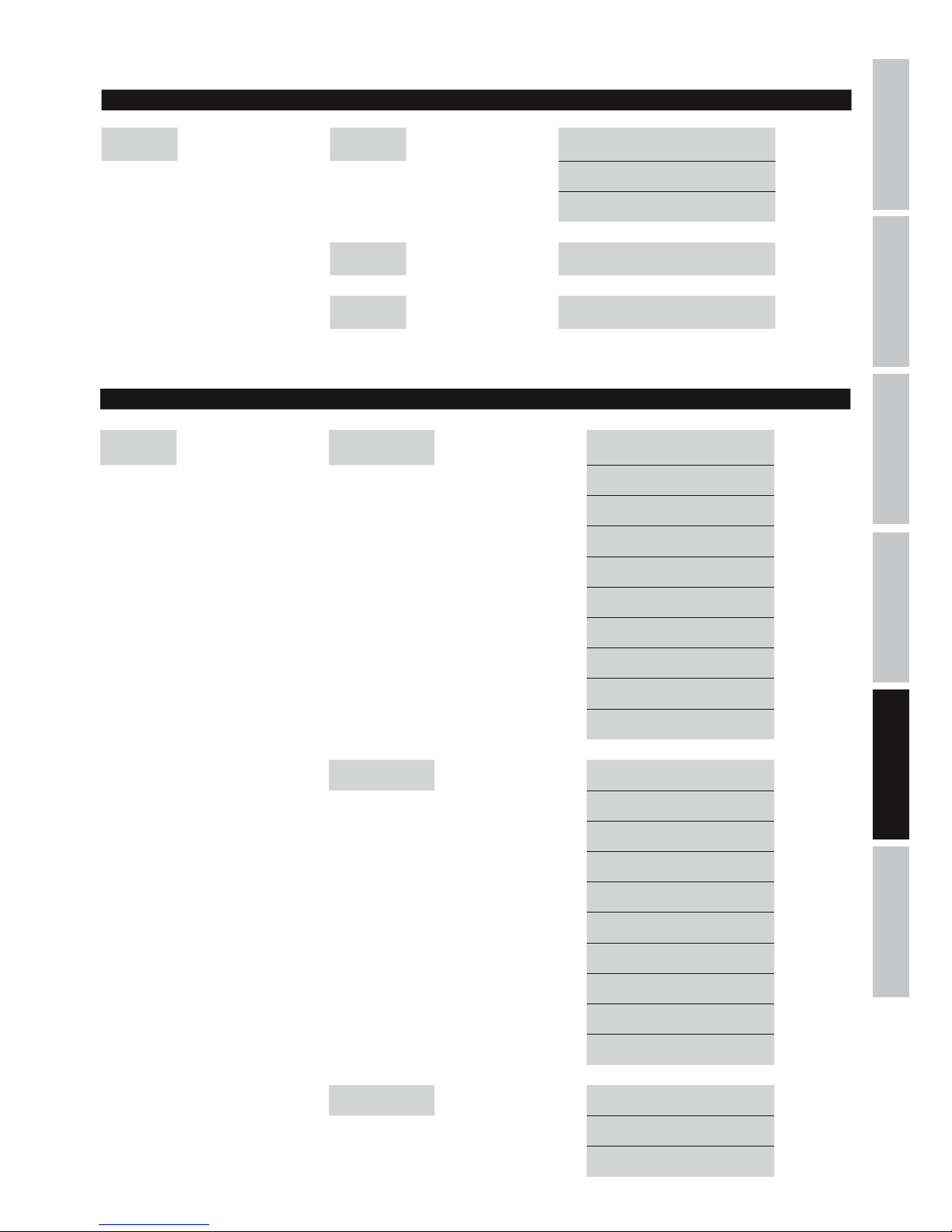
ITALIANOPOLSKIESPAÑOL
FRANCAISDEUTSCHENGLISH
49
STRUKTURA MENU – INPUTS A/B
STRUKTURA MENU OUTPUTS 1–6
Display: Display:
EDIT OUTPUT
1-6:
-> EDIT
1-6 ->
NAV/PM1 Out 1-6 HPF -> ENTER -> PM2 KHz <- ESC
PM3 No Cut-Off <- ESC
Butwrth 6 dB <- ESC
Butwrth 12 dB <- ESC
Lnk/Ril 12 dB <- ESC
Bessel 12 dB <- ESC
Butwrth 18 dB <- ESC
Butwrth 24 dB <- ESC
Lnk/Ril 24 dB <- ESC
Bessel 24 dB <- ESC
Out 1-6 LPF -> ENTER -> PM2 KHz <- ESC
PM3 No Cut-Off <- ESC
Butwrth 6 dB <- ESC
Butwrth 12 dB <- ESC
Lnk/Ril 12 dB <- ESC
Bessel 12 dB <- ESC
Butwrth 18 dB <- ESC
Butwrth 24 dB <- ESC
Lnk/Ril 24 dB <- ESC
Bessel 24 dB <- ESC
Out 1-6 EQ1-EQ7 -> ENTER -> NAV/PM1 KHz <- ESC
PM2 BW <- ESC
PM3 dB <- ESC
Display: Display:
EDIT INPUT
A/B:
-> EDIT
A/B ->
NAV/PM1
Input-A/B
EQ1-EQ5
-> ENTER -> NAV/PM1 KHz <- ESC
PM2 BW <- ESC
PM3 dB <- ESC
Input-A/B
Gain
-> ENTER -> PM2/3 dB <- ESC
Input-A/B
Delay
-> ENTER -> PM2/3
m/ms
(0 m...288,65932 m / 0 ms...848,998 ms)
<- ESC
Page 50
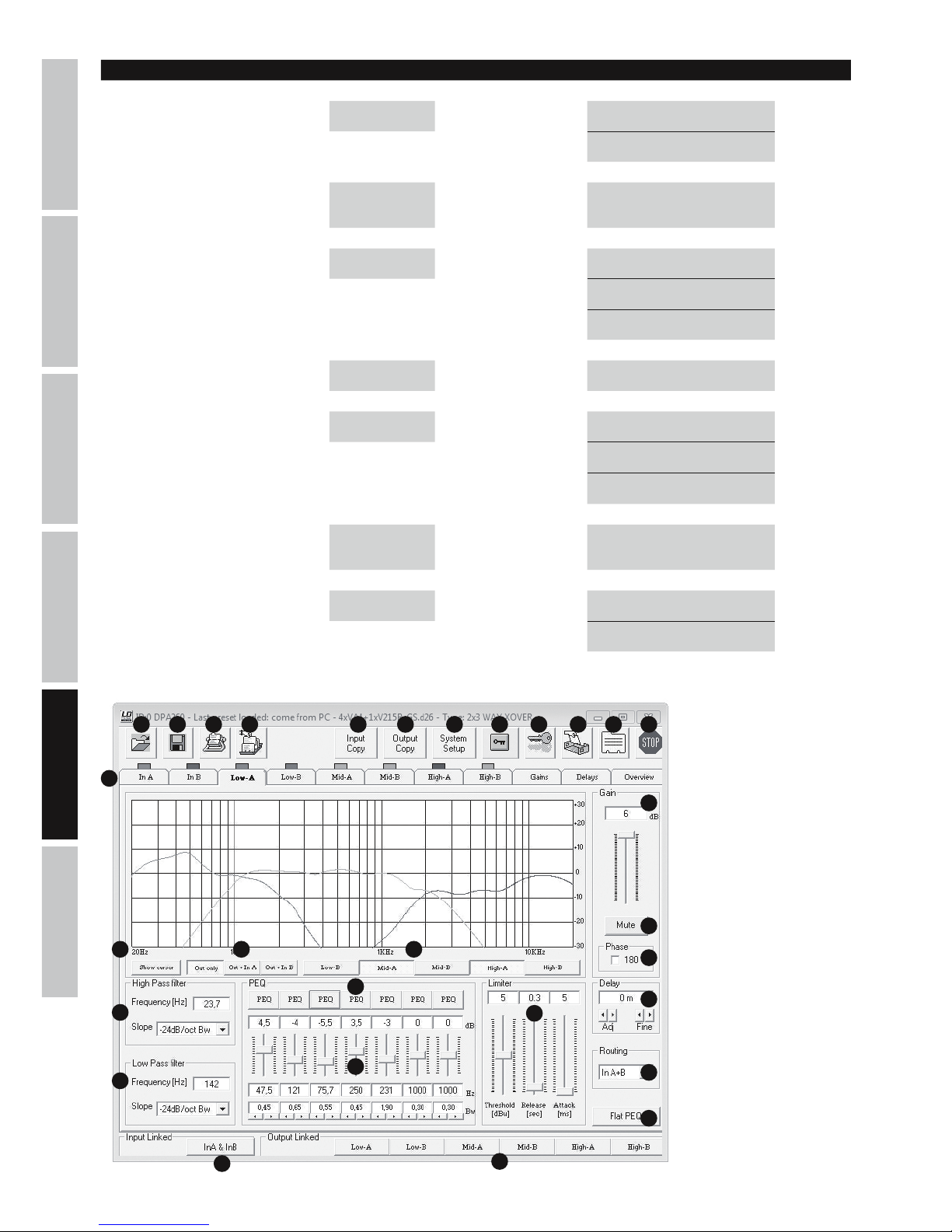
50
DEUTSCHFRANCAIS
ESPAÑOL
ENGLISH
ITALIANO POLSKI
PROGRAM LDDPA260 (PRZYKŁADOWY WIDOK)
1 2 3 4 5 6 7 109 11 12
13
1415 16
17
18
19
20
8
21
25
22
24
23
26
27
28
29
Out 1-6 Vu-Meter -> ENTER -> PM2/3 Level <- ESC
Limiter Act <- ESC
Out 1-6 Name -> ENTER ->
NAV/PM1
PM2/3
Name = xxxxxx -> ENTER <-
Out 1-6 Source -> ENTER -> PM2/3 InA <- ESC
InB <- ESC
InA+InB <- ESC
Out 1-6 Gain -> ENTER -> PM2/3 dB <- ESC
Out 1-6 Limiter -> ENTER -> NAV/PM1 Attack ms <- ESC
PM2 Release s <- ESC
PM3 dBu <- ESC
Out 1-6 Delay -> ENTER -> PM2/3
m/ms
(0 m...288,65932 m /
0 ms...848,998 ms)
<- ESC
Out 1-6 Polarity -> ENTER -> PM2/3 Normal <- ESC
Invert <- ESC
Display: Display:
Page 51
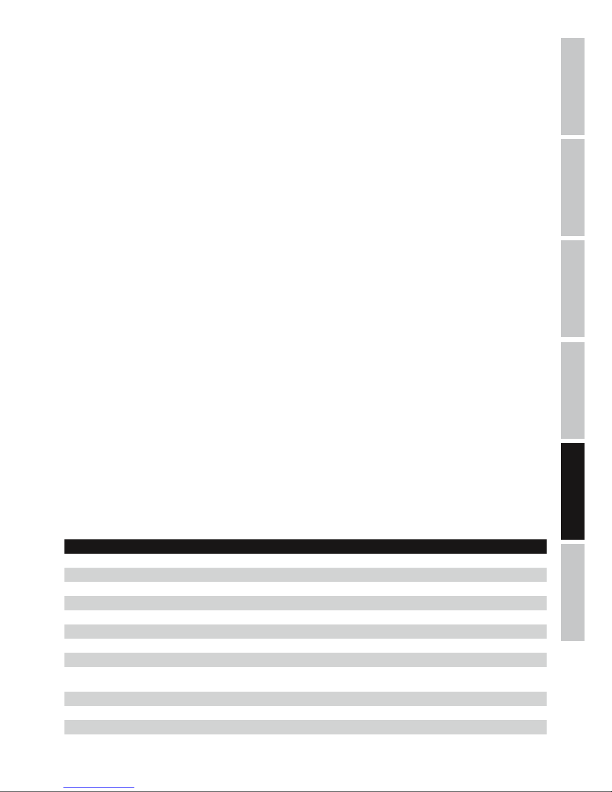
ITALIANOPOLSKIESPAÑOL
FRANCAISDEUTSCHENGLISH
51
PROGRAM DPA260
WSKAZÓWKA: jeśli kontroler DPA260 podłączony jest do komputera/programu za pomocą złącza USB lub RS485, wówczas wszystkie
elementy obsługi na przednim panelu kontrolera są zablokowane.
1. Otwieranie ustawień kontrolera zapisanych na nośniku pamięci.
2. Zapamiętanie zmienionych lub nowo utworzonych ustawień kontrolera na nośniku pamięci.
3. Przeniesienie ustawień do kontrolera DPA260. W jednostce DPA260 można zapisać do 24 ustawień kontrolera.
4. Wywołanie ustawień kontrolera z urządzenia DPA260.
5. Kopiowanie ustawień kanału wejściowego do innego kanału.
6. Kopiowanie ustawień kanału wyjściowego do innego kanału.
7. Konfiguracja funkcji zwrotnicy kontrolera DPA260 (2x2 WAY XOVER + SUB, 2x3 WAY XOVER, 6 WAY XOVER).
8. Blokowanie kanałów wyjściowych w programie. Jeśli funkcja blokady jest aktywna, można jedynie dokonywać zmian w kanałach
wejściowych (program).
9. Blokowanie kontrolera DPA260 (hasło składające się z 6 znaków). Blokada kontrolera jest aktywna także po zamknięciu programu i
odłączeniu od komputera. Można ją usunąć za pomocą programu lub funkcji odblokowania w kontrolerze DPA260.
10. Zmiana nazwy jednostki kontrolera DPA260.
11. Zmiana nazwy kanałów wejściowych i wyjściowych.
12. Odłączenie programu od kontrolera DPA260.
13. Wywołanie poszczególnych kanałów wejściowych i wyjściowych, ustawień Gain i Delay oraz widoku ogólnego.
14. Graficzne przedstawienie ustawień korektora wybranych kanałów.
15. Wskazanie kursora korektora wybranego kanału.
16. Określenie, czy ustawienia korektora mają być przedstawione graficznie tylko dla kanałów wyjściowych, czy łącznie dla kanałów
wejściowych i wyjściowych.
17. Ustawienia i wskazanie Gain dla wybranego kanału.
18. Wyciszenie wybranego kanału.
19. Inwersja biegunowości wybranego kanału.
20. Ustawienia Delay dla wybranego kanału (0 ms, 0,02 ms...848,998 ms / 0 m, 0,0068 m...288,65932 m).
21. Wybór źródła wejścia dla wybranego kanału.
22. Ustawienia filtra górnoprzepustowego dla wybranego kanału.
23. Ustawienia filtra dolnoprzepustowego dla wybranego kanału.
24. Korektor 7-pasmowy wybranego kanału wyjściowego (korektor 5-pasmowy dla kanałów wejściowych).
25. Regulacja charakterystyki korektora.
26. Zresetowanie ustawień korektora dla wybranego kanału.
27. Ustawienia limitera dla wybranego kanału.
28. Przycisk połączenia obu kanałów wejściowych.
29. Przyciski połączenia kanałów wyjściowych.
Oznaczenie modelu: LDDPA260
Rodzaj produktu: kontroler DSP
Typ: cyfrowy
Wersja: 6-kanałowy
Konwerter AD/DA: 24bity
Częstotliwość próbkowania: 48 kHz
Charakterystyka częstotliwościowa: 20–20 000 Hz
Typ filtra: Butterworth, Bessel, Linkwitz-Riley
Nachylenie zbocza filtra: 6, 12, 18, 24 dB/oktawa
Opóźnienie (kanały wejściowe i
wyjściowe):
0 ms, 0,02 ms...848,998 ms / 0 m, 0,0068 m...288,65932 m
Dynamika: 111 dB (uśrednienie A)
Stosunek sygnału do szumu: >106 dB
Współczynnik zniekształceń (THD): < 0,005%
Przesłuch między kanałami: 107 dB (+20 dBu @ 1 kHz)
SPECYFIKACJE
Page 52
52
DEUTSCHFRANCAIS
ESPAÑOL
ENGLISH
ITALIANO POLSKI
Maksymalny poziom wejściowy: +20 dBu (symetrycznie)
Maks. poziom wyjściowy: +20 dBu (symetrycznie)
Impedancja wejściowa: 27kΩ
Impedancja wyjściowa: 120Ω
Elementy obsługi: Nav/Par1, Par2, Par3, Enter, Escape, Utility
Edit Input 1–2, Edit Output 1–6
Wskaźniki: wielofunkcyjny wyświetlacz LCD, 2 x wskazanie modulacji poziomu wejściowego (6 segmentów), 2
x Input Clip, 2 x Input Edit LED, 2 x Input Mute LED, 6 x wskazanie modulacji poziomu wyjściowego
(5 segmentów),
6 x Output Clip, 6 x Output Limit, 6 x Output Edit LED, 6 x Output Mute LED
Wejścia liniowe: 3 (2 analogowe, 1 cyfrowe stereo)
Przyłącza wejściowe liniowe: XLR (symetryczne), S/PDIF (cinch)
Wyjścia liniowe: 6
Przyłącza wyjściowe liniowe: XLR (symetryczne)
Interfejs: USB, RS485 (In & Out)
Przyłącze zasilania sieciowego: gniazdo sieciowe IEC
Napięcie robocze: 90 V AC – 250 V AC
Pobór mocy: 14 W
Bezpiecznik: T800 mAL/250 V
Wymiary (szer. x wys. x gł.) 482 x 44,5 x 225 mm
DEKLARACJE PRODUCENTA
GWARANCJA PRODUCENTA I OGRANICZENIE ODPOWIEDZIALNOŚCI
Nasze aktualne warunki gwarancji i informacje dotyczące ograniczenia odpowiedzialności znajdą Państwo na stronie: http://www.adamhall.
com/media/shop/downloads/documents/manufacturersdeclarations.pdf. W razie konieczności skorzystania z serwisu proszę skontaktować
się z firmą Adam Hall GmbH, Daimlerstraße 9, 61267 Neu Anspach / e-mail [email protected] / +49 (0)6081 / 9419-0.
PRAWIDŁOWA UTYLIZACJA NINIEJSZEGO PRODUKTU
(Obowiązuje w Unii Europejskiej i innych krajach europejskich stosujących system sortowania odpadów) Niniejszy symbol na produkcie lub
związanych z nim dokumentach wskazuje, iż urządzenie po zakończeniu okresu użytkowania nie może być utylizowane razem ze standardowymi odpadami domowymi, aby uniknąć szkód w środowisku lub szkód na osobie powstałych w wyniku niekontrolowanego usuwania odpadów.
Niniejszy produkt należy utylizować oddzielnie od innych odpadów i przekazać do punktu recyklingu w celu ponownego wykorzystania użytych w
nim materiałów w ramach idei zrównoważonego rozwoju. Klienci prywatni otrzymują informacje w zakresie przyjaznych dla środowiska możliwości
usuwania odpadów od sprzedawcy, u którego produkt został zakupiony, lub w odpowiednich placówkach regionalnych. Użytkownicy będący
przedsiębiorcami proszeni są o kontakt ze swoimi dostawcami i ewentualne sprawdzenie uzgodnionych umownie warunków utylizacji urządzeń.
Niniejszy produkt nie może być utylizowany razem z innymi odpadami przemysłowymi.
Deklaracja zgodności CE
Firma Adam Hall GmbH niniejszym oświadcza, że produkt ten jest zgodny z następującymi dyrektywami (o ile mają zastosowanie):
dyrektywa w sprawie urządzeń radiowych i końcowych urządzeń telekomunikacyjnych (1999/5/WE) lub dyrektywa w sprawie urządzeń
radiowych (2014/53/UE) od czerwca 2017 r.
dyrektywa niskonapięciowa (2014/35/UE)
dyrektywa w sprawie kompatybilności elektromagnetycznej (2014/30/UE)
dyrektywa w sprawie ograniczenia stosowania niektórych niebezpiecznych substancji w sprzęcie elektrycznym i elektronicznym (2011/65/UE)
Pełna wersja deklaracji zgodności znajduje się na stronie internetowej www.adamhall.com.
Ponadto zapytania w tej sprawie można przesyłać na adres e-mail [email protected].
Page 53
ITALIANOPOLSKIESPAÑOL
FRANCAISDEUTSCHENGLISH
53
ITALIANO
AVETE FATTO LA SCELTA GIUSTA!
Quest‘apparecchio è stato sviluppato e prodotto secondo elevati standard qualitativi che garantiscono un funzionamento regolare per molti
anni. Per questo motivo LD Systems, con il suo nome e la pluriennale esperienza, rappresenta un‘azienda produttrice di prodotti audio di
qualità. Leggete attentamente questo manuale d‘uso per utilizzare al meglio il vostro nuovo prodotto LD Systems.
Per maggiori informazioni su LD SYSTEMS, consultate la nostra pagina web WWW.LD-SYSTEMS.COM
MISURE PRECAUZIONALI
1. Leggere attentamente il presente manuale di istruzioni.
2. Conservare tutte le indicazioni e le istruzioni in un luogo sicuro.
3. Seguire le istruzioni.
4. Rispettare tutte le avvertenze. Non rimuovere dal dispositivo le indicazioni sulla sicurezza o altre informazioni.
5. Utilizzare il dispositivo solo nei modi previsti dal manuale.
6. Utilizzare esclusivamente stativi e fissaggi stabili e adatti (per installazioni fisse). Verificare che i supporti a parete siano installati e fissati
a regola d‘arte. Verificare che il dispositivo sia installato in modo stabile e non possa cadere.
7. Durante l‘installazione, osservare le normative sulla sicurezza in vigore nel proprio Paese.
8. Non installare né azionare il dispositivo in prossimità di radiatori, accumulatori termici, stufe o altre fonti di calore. Accertarsi che il
dispositivo sia sempre installato in modo che venga raffreddato a sufficienza e non possa surriscaldarsi.
9. Non appoggiare sul dispositivo fonti di combustione, quali candele accese.
10. Le fessure di areazione non devono essere bloccate. Evitare l‘esposizione diretta ai raggi solari.
11. Non attivare il dispositivo nelle immediate vicinanze di acqua (questo punto non interessa i dispositivi specifici per l‘esterno, per i quali
valgono le speciali indicazioni riportate di seguito). Non portare mai il dispositivo a contatto con materiali, liquidi o gas infiammabili.
12. Accertarsi che all‘interno del dispositivo non possa penetrare acqua per gocciolamento o spruzzo. Non collocare sul dispositivo oggetti
contenenti liquidi, quali vasi, tazze o bicchieri.
13. Assicurarsi che non sia possibile la caduta di oggetti nel dispositivo.
14. Azionare il dispositivo esclusivamente con gli accessori appositamente consigliati e previsti dal produttore.
15. Non aprire né modificare il dispositivo.
16. Una volta collegato il dispositivo, verificare tutti i cavi per evitare danni o incidenti, ad esempio per inciampo.
17. Durante il trasporto, assicurarsi che il dispositivo non possa cadere e causare possibili danni a cose e/o persone.
18. Se il dispositivo non funzionasse più correttamente, vi fosse caduto sopra del liquido o un oggetto o fosse stato danneggiato in altro
modo, spegnerlo immediatamente e staccare la spina (se si tratta di un dispositivo attivo). La riparazione del dispositivo deve essere affidata
esclusivamente a personale qualificato autorizzato.
19. Per la pulizia del dispositivo utilizzare un panno pulito.
20. Rispettare le leggi sullo smaltimento in vigore nel Paese di installazione. Al momento di smaltire l‘imballo, separare la plastica dalla
carta e dal cartone.
21. I sacchetti di plastica devono essere tenuti lontani dalla portata dei bambini.
DISPOSITIVI CON ALLACCIAMENTO DI RETE
22. ATTENZIONE: se il cavo di rete è dotato di contatto di protezione, deve essere collegato a una presa di rete con messa a terra. Non
disattivare mai la connessione di messa a terra di un cavo di rete.
23. Non accendere il dispositivo subito dopo essere stato sottoposto a forti variazioni di temperatura (ad esempio dopo il trasporto). Umidità
e condensa potrebbero danneggiare il dispositivo. Accendere il dispositivo solo dopo che ha raggiunto la temperatura ambiente.
24. Prima di collegare il dispositivo alla presa, controllare innanzitutto se la tensione e la frequenza della rete elettrica coincidono con i
valori indicati sul dispositivo stesso. Nel caso di dispositivo munito di selettore di tensione, collegarlo alla presa unicamente se i valori del
dispositivo coincidono con quelli della rete elettrica. Se il cavo di rete o l‘adattatore di rete forniti in dotazione non sono compatibili con la
presa, rivolgersi a un elettricista.
25. Non calpestare il cavo di rete. Accertarsi che i cavi sotto tensione, in particolare della presa di rete o dell‘adattatore di rete,
non vengano pizzicati.
26. Durante il cablaggio del dispositivo, verificare sempre che il cavo di rete e l‘adattatore di rete siano costantemente accessibili. Staccare
sempre il dispositivo dall‘alimentazione di rete quando non è utilizzato o durante la pulizia. Per staccare dalla presa il cavo di rete e l‘adattatore
di rete, tirare sempre dalla spina o dall‘adattatore e non dal cavo. Non toccare mai il cavo di alimentazione e l’alimentatore con le mani umide.
27. Evitare per quanto possibile di accendere e spegnere velocemente il dispositivo per non pregiudicarne la durata.
28. NOTA IMPORTANTE: Sostituire i fusibili esclusivamente con fusibili dello stesso tipo e valore. Se un fusibile continua a saltare, rivolgersi a
un centro di assistenza autorizzato.
29. Per staccare completamente il dispositivo dalla rete elettrica, rimuovere il cavo di rete o l‘adattatore di rete dalla presa.
30. Per staccare un dispositivo provvisto di presa Volex, è prima necessario sbloccare la relativa spina Volex del dispositivo stesso. Tirando il
cavo di rete, però, il dispositivo potrebbe spostarsi e cadere, provocando danni alle persone o di altro genere. Prestare quindi la più scrupolosa
attenzione durante la posa dei cavi.
31. In caso di pericolo di caduta di fulmine, o se il dispositivo rimane inutilizzato a lungo, staccare sempre il cavo di rete e l‘adattatore di
rete dalla presa.
Page 54
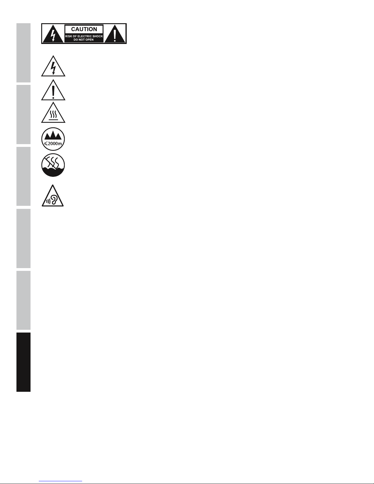
54
DEUTSCHFRANCAIS
ESPAÑOL
ENGLISH
ITALIANO POLSKI
ATTENZIONE:
non togliere mai il coperchio di protezione perché sussiste il pericolo di scosse elettriche.
L‘interno del dispositivo non contiene parti che possono essere riparate o sottoposte a
manutenzione da parte dell‘utente. Per gli interventi di manutenzione e di riparazione rivolgersi
esclusivamente a personale qualificato.
Il triangolo equilatero con il simbolo del lampo segnala la presenza di tensioni pericolose non isolate all‘interno
dell‘apparecchio che possono causare scosse elettriche.
Il triangolo equilatero con punto esclamativo segnala la presenza di importanti informazioni relative all’uso e alla manutenzione.
Avvertimento! Questo simbolo indica superfici calde. Alcune parti della cassa potrebbero scaldarsi durante l‘impiego. Dopo aver
usato l‘apparecchiatura, lasciarla raffreddare per almeno 10 minuti prima di toccarla o trasportarla.
Avvertimento! Questo dispositivo è destinato per l’utilizzo a un’altitudine non superiore ai 2.000metri sul livello del mare.
Avvertimento! Questo dispositivo non è destinato all’uso nei climi tropicali.
Per evitare possibili danni all‘udito, evitare l‘ascolto ad un volume elevato per periodi prolungati.
L‘esposizione al volume elevato può causare danni all‘udito anche se è di breve durata. Mantenere sempre il volume ad un
livello gradevole.
ATTENZIONE! PRODOTTI AUDIO con LIVELLI SONORI ELEVATI!
Questo dispositivo è destinato a uso professionale. Il suo utilizzo in ambito commerciale è soggetto alle normative e alle direttive nazionali
vigenti in materia di prevenzione di infortuni. In qualità di produttore, Adam Hall è tenuto per legge a informare espressamente gli utenti
degli eventuali rischi per la salute. Danni all‘udito provocati da un’esposizione prolungata a un livello sonoro elevato: l‘utilizzo di questo
prodotto può generare elevati livelli di pressione sonora (SPL) che possono provocare danni irreparabili all‘udito di artisti, collaboratori e
spettatori. Evitare l‘esposizione prolungata a livelli sonori elevati, superiori a 90dB.
Page 55
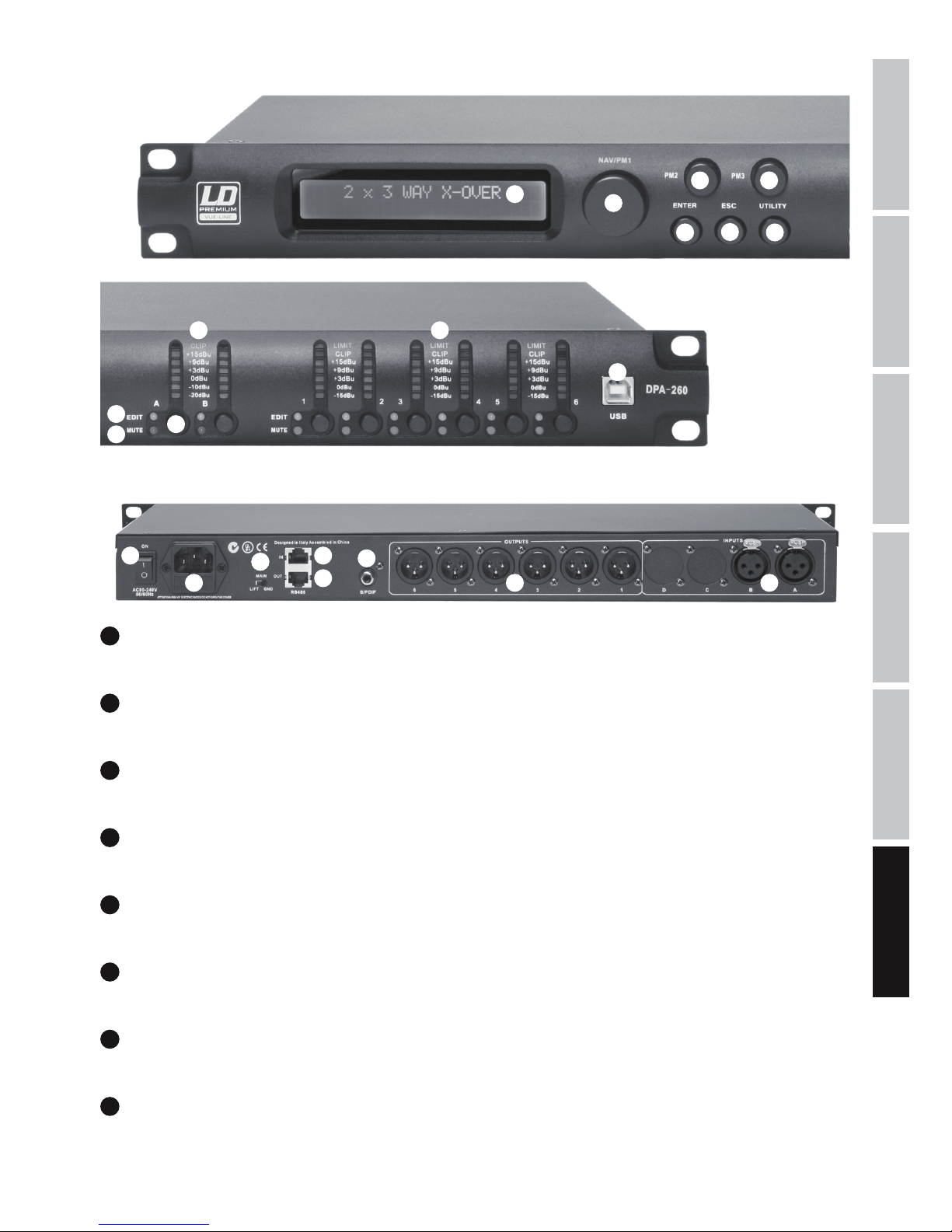
ITALIANOPOLSKIESPAÑOL
FRANCAISDEUTSCHENGLISH
55
CONNESSIONI, COMANDI E INDICATORI
1
2
3
4
5
6 7
9
12
13
14
15
16
17
18
19
20 21
8
10
11
1
DISPLAY
Display LCD illuminato, multifunzione, da 2 x 24caratteri.
2
UTILITY
Per effettuare modifiche del dispositivo nel menu di elaborazione, premere il tasto UTILITY.
3
NAV/PM1
Dopo aver premuto il tasto UTILITY, selezionare le voci di menu nel menu principale e nei sottomenu con la manopola NAV/PM1.
4
ENTER
Premere ENTER per accedere a un livello inferiore nella struttura di menu e confermare le modifiche ai parametri.
5
ESC
Premere il tasto ESC per accedere a un livello superiore della struttura di menu e per tornare alla videata principale.
6
PM2
Utilizzare la manopola PM2 per modificare i parametri di una voce di menu. Confermare l'inserimento premendo ENTER.
7
PM3
Utilizzare la manopola PM3 per modificare i parametri di una voce di menu. Confermare l'inserimento premendo ENTER.
8
INPUT METER A / B
VU meter di LED a 7segmenti del livello di segnale dei canali di ingresso A e B. Non appena il LED CLIP rosso sull'estremità superiore del VU
meter si accende, abbassare il livello di uscita del dispositivo di riproduzione (ad esempio il mixer) per evitare distorsioni (max +20dBu).
Page 56
56
DEUTSCHFRANCAIS
ESPAÑOL
ENGLISH
ITALIANO POLSKI
9
OUTPUT METER 1 - 6
VU meter di LED a 7segmenti del livello di segnale dei canali di uscita1-6. Per evitare distorsioni, ridurre il livello del canale di uscita corrispondente non appena il LED CLIP rosso si accende. Il LED LIMIT giallo si accende quando il limitatore integrato limita il segnale di uscita
del canale corrispondente (impostare il limitatore come i componenti del sistema).
10
EDIT-LED
Premere brevemente il tasto (12) del canale di ingresso o uscita corrispondente per accedere alla modalità di modifica del canale. Il LED
EDIT azzurro del canale selezionato si accende. Per uscire dalla modalità di modifica del canale, premere di nuovo brevemente il tasto (12).
Il LED EDIT azzurro si spegne.
11
MUTE-LED
Premere per circa due secondi il tasto (12) del canale di ingresso o uscita desiderato per silenziare il canale. Il LED MUTE rosso del canale
selezionato si accende. Per terminare il silenziamento del canale, premere di nuovo il tasto (12) per circa 2 secondi. Il segnale audio viene
emesso di nuovo e il LED MUTE rosso si spegne.
12
/ TASTI FUNZIONE DI INGRESSO A/B E USCITA 1-6
Attivare il tasto per attivare le funzioni descritte ai punti10 e 11.
13
USB-PORT
La porta USB consente di modificare e gestire tutte le funzioni e i preset del controller LDDPA260 DSP tramite un computer Windows. Il
software e i driver per i sistemi operativi Windows sono forniti di serie con il dispositivo ma possono anche essere scaricati dalla nostra
pagina web WWW.LD-SYSTEMS.COM, come i preset per una molteplicità di altoparlanti di LD Systems.
14
ON
Interruttore di accensione/spegnimento del dispositivo.
15
PRESA DI RETE IEC CON PORTAFUSIBILE INTEGRATO
Serve per l'alimentazione di tensione del dispositivo. In dotazione viene fornito un cavo di rete idoneo. NOTE IMPORTANTI: sostituire il
fusibile esclusivamente con un fusibile dello stesso tipo e con gli stessi valori (T800mAL/250V)! Se il fusibile continua a saltare, rivolgersi a
un centro di assistenza autorizzato.
16
GROUND LIFT
Permette di evitare ritorni di terra non appena vengono collegati apparecchi con potenziale di terra diverso.
17
RS485 IN
Collegando l'adattatore LDDPA260RC a RS-485, questo connettore consente di telecomandare l'LDDPA260 da FOH tramite un comune cavo
XLR multipolare e un computer con Windows.
18
RS485 OUT
Si utilizza per inoltrare il segnale di comando a uno o più controller LDDPA260 supplementari.
19
S/PDIF
Ingresso stereo digitale con cavo coassiale di formato S/PDIF.
20
OUTPUTS 1 - 6
Uscite audio bilanciate con prese XLR maschio a 3poli.
21
INPUTS A + B
Ingressi audio bilanciati con prese XLR femmina a 3poli.
Page 57
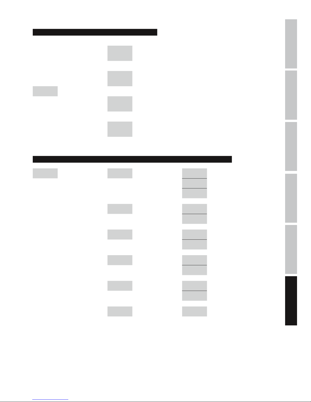
ITALIANOPOLSKIESPAÑOL
FRANCAISDEUTSCHENGLISH
57
STRUTTURA DI MENU: UTILITY
Display: Display:
System Utilities
-> ENTER ->
<- ESC
Program Utilities
-> ENTER ->
<- ESC
Main Menu UTILITY NAV/PM1
Interface
Utilities
-> ENTER ->
<- ESC
Security Utilities
-> ENTER ->
<- ESC
STRUTTURA DI MENU: SYSTEM UTILITIES
Display: Display: Display:
System Utilities
-> ENTER ->
<- ESC
NAV/PM1 System Setup
-> ENTER ->
<- ESC
PM2/3 2x2 WAY + SUB -> ENTER <-
2x3 WAY XOVER -> ENTER <-
6 WAY XOVER -> ENTER <-
Input Routing
-> ENTER ->
<- ESC
PM2/3 Source : Analog -> ENTER <-
Source : Digital -> ENTER <-
Power-On
Procedure
-> ENTER ->
<- ESC
PM2/3 Fade-In : On -> ENTER <-
Fade-In : Off -> ENTER <-
Delay Units
-> ENTER ->
<- ESC
PM2/3
Unit : Distan-
ce(m)
-> ENTER <-
Unit : Time(ms) -> ENTER <-
Ramps on
changes
-> ENTER ->
<- ESC
PM2/3 Ramps : On -> ENTER <-
Ramps : Off -> ENTER <-
Software
Version
-> ENTER ->
<- ESC
Version : V1.xx <- ESC
Page 58
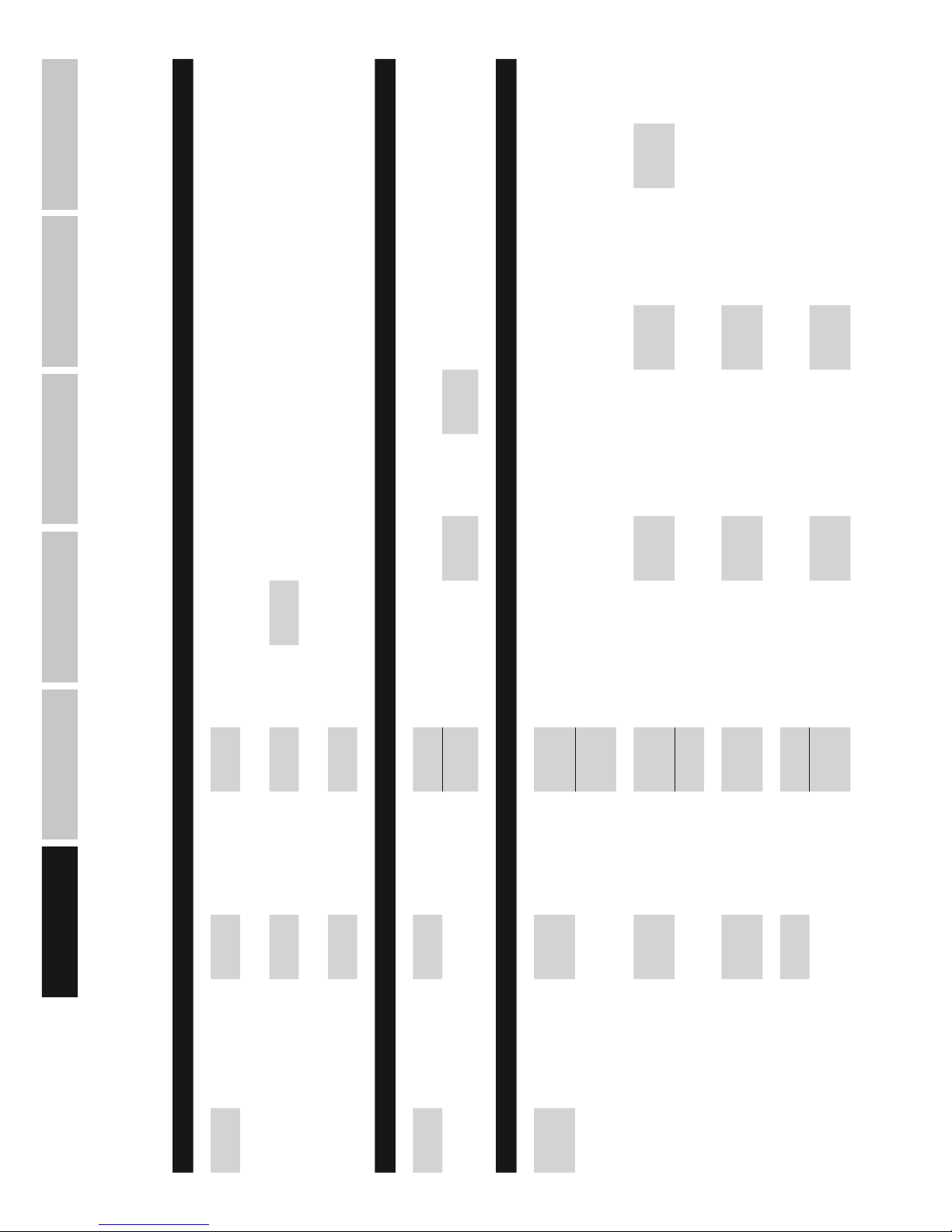
58
DEUTSCHFRANCAIS
ESPAÑOL
ENGLISH
ITALIANO POLSKI
Display: Display: Display: Display:
Program
Utilities
-> ENTER ->
<- ESC
NAV/PM1
Recall a
Program
-> ENTER ->
<- ESC
PM2/3 01 - 24
-> 2x ENTER <-
<- ESC
Save a
Program
-> ENTER ->
<- ESC
PM2/3 01 - 24
-> ENTER ->
<- ESC
Set Program
Name
NAV/PM1
PM2/3
-> 2x ENTER <-
<- ESC
Delete a
Program
-> ENTER ->
<- ESC
PM2/3 01 - 24
-> 2x ENTER <-
<- ESC
Display: Display: Display: Display: Display:
Interface
Utilities
-> ENTER ->
<- ESC
Interface
Setup
-> ENTER ->
<- ESC
PM2/3 Source : USB
-> ENTER
<- ESC
Source :
RS485
-> ENTER ->
<- ESC
NAV/PM1
Remote ID
Num = xx
PM2/3
Remote ID
Num = 01
- 32
-> ENTER
<- ESC
Display: Display: Display: Display: Display: Display:
Security
Utilities
-> ENTER ->
<- ESC
NAV/PM1
Show
Parameter
-> ENTER ->
<- ESC
PM2/3
Parameter
will be
shown
-> ENTER <-
Parameter
will not be
shown
-> ENTER <-
Lock Unit
-> ENTER ->
<- ESC
PM2/3 Lock : On
-> ENTER ->
<- ESC
Main Menu
(Menu
locked)
(to unlock)
UTILITY ->
Lock Unit -> ENTER -> PM2/3 Lock : Off -> ENTER <-
Lock : Off -> ENTER <-
User
Password
-> ENTER ->
<- ESC
NAV/PM1
PM2/3
User
Password
[000000]
-> ENTER ->
<- ESC
NAV/PM1
PM2/3
New
Password
[xxxxxx]
-> ENTER ->
<- ESC
NAV/PM1
PM2/3
Confirm
Password
[xxxxxx]
-> ENTER <-
Enable
Password
-> ENTER ->
<- ESC
PM2/3
Password :
Disable
-> ENTER
Password :
Enable
-> ENTER ->
Main Menu
(Menu
locked)
(to unlock)
UTILITY ->
User
Password
[xxxxxx]
-> ENTER <-
STRUTTURA DI MENU: PROGRAMM UTILITIES, INTERFACE UTILITIES, SECURITY UTILITIES
Page 59
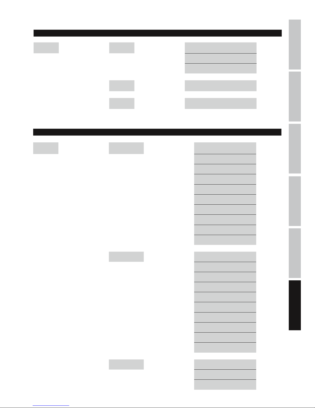
ITALIANOPOLSKIESPAÑOL
FRANCAISDEUTSCHENGLISH
59
STRUTTURA DI MENU: INPUT A/B
STRUTTURA MENU: OUTPUT 1-6
Display: Display:
EDIT OUTPUT
1-6:
-> EDIT
1-6 ->
NAV/PM1 Out 1-6 HPF -> ENTER -> PM2 KHz <- ESC
PM3 No Cut-Off <- ESC
Butwrth 6 dB <- ESC
Butwrth 12 dB <- ESC
Lnk/Ril 12 dB <- ESC
Bessel 12 dB <- ESC
Butwrth 18 dB <- ESC
Butwrth 24 dB <- ESC
Lnk/Ril 24 dB <- ESC
Bessel 24 dB <- ESC
Out 1-6 LPF -> ENTER -> PM2 KHz <- ESC
PM3 No Cut-Off <- ESC
Butwrth 6 dB <- ESC
Butwrth 12 dB <- ESC
Lnk/Ril 12 dB <- ESC
Bessel 12 dB <- ESC
Butwrth 18 dB <- ESC
Butwrth 24 dB <- ESC
Lnk/Ril 24 dB <- ESC
Bessel 24 dB <- ESC
Out 1-6 EQ1-EQ7 -> ENTER -> NAV/PM1 KHz <- ESC
PM2 BW <- ESC
PM3 dB <- ESC
Display: Display:
EDIT INPUT
A/B:
-> EDIT
A/B ->
NAV/PM1
Input-A/B
EQ1-EQ5
-> ENTER -> NAV/PM1 KHz <- ESC
PM2 BW <- ESC
PM3 dB <- ESC
Input-A/B
Gain
-> ENTER -> PM2/3 dB <- ESC
Input-A/B
Delay
-> ENTER -> PM2/3
m/ms
(0 m...288,65932 m / 0 ms...848,998 ms)
<- ESC
Page 60
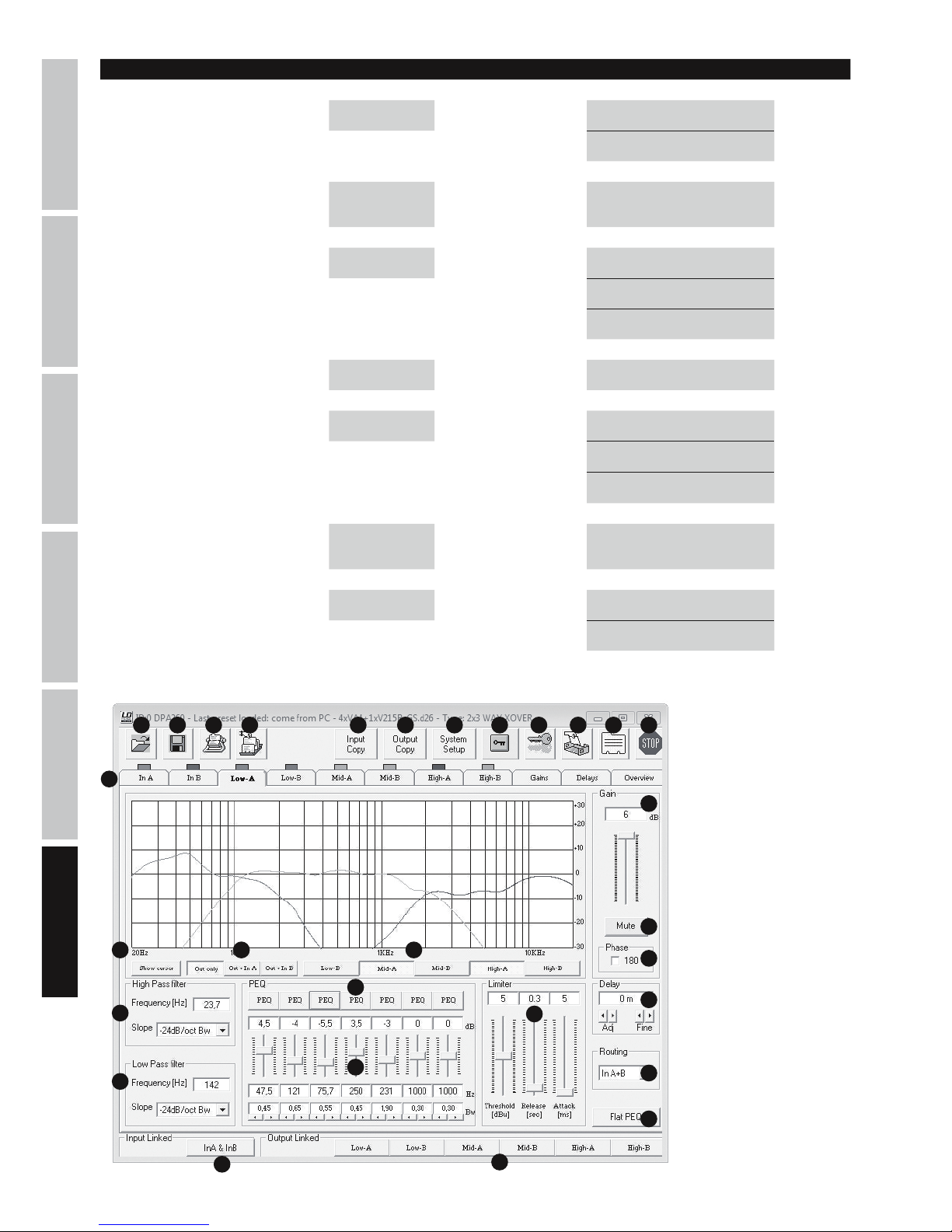
60
DEUTSCHFRANCAIS
ESPAÑOL
ENGLISH
ITALIANO POLSKI
SOFTWARE LDDPA260 (IMMAGINE DI ESEMPIO)
1 2 3 4 5 6 7 109 11 12
13
1415 16
17
18
19
20
8
21
25
22
24
23
26
27
28
29
Out 1-6 Vu-Meter -> ENTER -> PM2/3 Level <- ESC
Limiter Act <- ESC
Out 1-6 Name -> ENTER ->
NAV/PM1
PM2/3
Name = xxxxxx -> ENTER <-
Out 1-6 Source -> ENTER -> PM2/3 InA <- ESC
InB <- ESC
InA+InB <- ESC
Out 1-6 Gain -> ENTER -> PM2/3 dB <- ESC
Out 1-6 Limiter -> ENTER -> NAV/PM1 Attack ms <- ESC
PM2 Release s <- ESC
PM3 dBu <- ESC
Out 1-6 Delay -> ENTER -> PM2/3
m/ms
(0 m...288,65932 m /
0 ms...848,998 ms)
<- ESC
Out 1-6 Polarity -> ENTER -> PM2/3 Normal <- ESC
Invert <- ESC
Display: Display:
Page 61

ITALIANOPOLSKIESPAÑOL
FRANCAISDEUTSCHENGLISH
61
SOFTWARE DPA260
WSKAZÓWKA: jeśli kontroler DPA260 podłączony jest do komputera/programu za pomocą złącza USB lub RS485, wówczas wszystkie
elementy obsługi na przednim panelu kontrolera są zablokowane.
1. Otwieranie ustawień kontrolera zapisanych na nośniku pamięci.
2. Zapamiętanie zmienionych lub nowo utworzonych ustawień kontrolera na nośniku pamięci.
3. Przeniesienie ustawień do kontrolera DPA260. W jednostce DPA260 można zapisać do 24 ustawień kontrolera.
4. Wywołanie ustawień kontrolera z urządzenia DPA260.
5. Kopiowanie ustawień kanału wejściowego do innego kanału.
6. Kopiowanie ustawień kanału wyjściowego do innego kanału.
7. Konfiguracja funkcji zwrotnicy kontrolera DPA260 (2x2 WAY XOVER + SUB, 2x3 WAY XOVER, 6 WAY XOVER).
8. Blokowanie kanałów wyjściowych w programie. Jeśli funkcja blokady jest aktywna, można jedynie dokonywać zmian w kanałach
wejściowych (program).
9. Blokowanie kontrolera DPA260 (hasło składające się z 6 znaków). Blokada kontrolera jest aktywna także po zamknięciu programu i
odłączeniu od komputera. Można ją usunąć za pomocą programu lub funkcji odblokowania w kontrolerze DPA260.
10. Zmiana nazwy jednostki kontrolera DPA260.
11. Zmiana nazwy kanałów wejściowych i wyjściowych.
12. Odłączenie programu od kontrolera DPA260.
13. Wywołanie poszczególnych kanałów wejściowych i wyjściowych, ustawień Gain i Delay oraz widoku ogólnego.
14. Graficzne przedstawienie ustawień korektora wybranych kanałów.
15. Wskazanie kursora korektora wybranego kanału.
16. Określenie, czy ustawienia korektora mają być przedstawione graficznie tylko dla kanałów wyjściowych, czy łącznie dla kanałów
wejściowych i wyjściowych.
17. Ustawienia i wskazanie Gain dla wybranego kanału.
18. Wyciszenie wybranego kanału.
19. Inwersja biegunowości wybranego kanału.
20. Ustawienia Delay dla wybranego kanału (0 ms, 0,02 ms...848,998 ms / 0 m, 0,0068 m...288,65932 m).
21. Wybór źródła wejścia dla wybranego kanału.
22. Ustawienia filtra górnoprzepustowego dla wybranego kanału.
23. Ustawienia filtra dolnoprzepustowego dla wybranego kanału.
24. Korektor 7-pasmowy wybranego kanału wyjściowego (korektor 5-pasmowy dla kanałów wejściowych).
25. Regulacja charakterystyki korektora.
26. Zresetowanie ustawień korektora dla wybranego kanału.
27. Ustawienia limitera dla wybranego kanału.
28. Przycisk połączenia obu kanałów wejściowych.
29. Przyciski połączenia kanałów wyjściowych.
SPECIFICHE
Oznaczenie modelu: LDDPA260
Rodzaj produktu: kontroler DSP
Typ: cyfrowy
Wersja: 6-kanałowy
Konwerter AD/DA: 24bity
Częstotliwość próbkowania: 48 kHz
Charakterystyka częstotliwościowa: 20–20 000 Hz
Typ filtra: Butterworth, Bessel, Linkwitz-Riley
Nachylenie zbocza filtra: 6, 12, 18, 24 dB/oktawa
Delay (canali di ingresso e di uscita): 0 ms, 0,02 ms...848,998 ms / 0 m, 0,0068 m...288,65932 m
Dynamika: 111 dB (uśrednienie A)
Stosunek sygnału do szumu: >106 dB
Współczynnik zniekształceń (THD): < 0,005%
Przesłuch między kanałami: 107 dB (+20 dBu @ 1 kHz)
Maksymalny poziom wejściowy: +20 dBu (symetrycznie)
Page 62
62
DEUTSCHFRANCAIS
ESPAÑOL
ENGLISH
ITALIANO POLSKI
Maks. poziom wyjściowy: +20 dBu (symetrycznie)
Impedancja wejściowa: 27kΩ
Impedancja wyjściowa: 120Ω
Elementy obsługi: Nav/Par1, Par2, Par3, Enter, Escape, Utility
Edit Input 1–2, Edit Output 1–6
Wskaźniki: wielofunkcyjny wyświetlacz LCD, 2 x wskazanie modulacji poziomu wejściowego (6 segmentów), 2
x Input Clip, 2 x Input Edit LED, 2 x Input Mute LED, 6 x wskazanie modulacji poziomu wyjściowego
(5 segmentów),
6 x Output Clip, 6 x Output Limit, 6 x Output Edit LED, 6 x Output Mute LED
Wejścia liniowe: 3 (2 analogowe, 1 cyfrowe stereo)
Przyłącza wejściowe liniowe: XLR (symetryczne), S/PDIF (cinch)
Wyjścia liniowe: 6
Przyłącza wyjściowe liniowe: XLR (symetryczne)
Interfejs: USB, RS485 (In & Out)
Przyłącze zasilania sieciowego: gniazdo sieciowe IEC
Napięcie robocze: 90 V AC – 250 V AC
Pobór mocy: 14 W
Bezpiecznik: T800 mAL/250 V
Wymiary (szer. x wys. x gł.) 482 x 44,5 x 225 mm
DICHIARAZIONI DEL PRODUTTORE
MANUFACTURER’S WARRANTY & LIMITATION OF LIABILITY
Le nostre attuali condizioni di garanzia e la limitazione di responsabilità sono consultabili alla pagina: http://www.adamhall.com/media/
shop/downloads/documents/manufacturersdeclarations.pdf. In caso di assistenza, rivolgersi a Adam Hall GmbH, Daimlerstraße 9,
61267 Neu Anspach / E-mail [email protected] / +49 (0)6081 / 9419-0.
CORRETTO SMALTIMENTO DEL PRODOTTO
(In vigore nell‘Unione Europea e in altri Paesi europei in cui si attui la raccolta differenziata) Questo simbolo apposto sul prodotto o
sui relativi documenti indica che, per evitare danni all‘ambiente e alle persone causati da uno smaltimento incontrollato dei rifiuti,
alla fine del suo ciclo di vita l‘apparecchio non deve essere smaltito insieme ai normali rifiuti domestici. Il prodotto deve quindi essere
smaltito separatamente da altri rifiuti e riciclato nell‘ottica dell‘incentivazione di cicli economici sostenibili. I clienti privati possono richiedere
informazioni sulle possibilità di smaltimento ecosostenibile al rivenditore presso il quale è stato acquistato il prodotto o presso le autorità
regionali competenti. I clienti aziendali devono invece contattare il proprio fornitore e controllare le eventuali condizioni contrattuali inerenti
allo smaltimento degli apparecchi. Questo prodotto non deve essere smaltito assieme ad altri rifiuti industriali.
Conformità CE
Con la presente Adam Hall GmbH dichiara che questo prodotto soddisfa le seguenti direttive (ove pertinente):
Direttiva R&TTE (1999/5/CE) e RED (2014/53/UE) da giugno 2017
Direttiva bassa tensione (2014/35/CE)
Direttiva CEM (2014/30/UE)
RoHS (2011/65/UE)
La dichiarazione di conformità completa è reperibile al sito www.adamhall.com.
Per ulteriori informazioni è inoltre possibile scrivere a [email protected].
Page 63
ITALIANOPOLSKIESPAÑOL
FRANCAISDEUTSCHENGLISH
63
Page 64
Adam Hall GmbH | Daimlerstrasse 9 | 61267 Neu-Anspach | Germany
Tel. +49(0)6081/9419-0 | Fax +49(0)6081/9419-1000
web : www.adamhall.com | e-mail : [email protected]
WWW.LD-SYSTEMS.COM
REV: 02
 Loading...