

Page 1
USER´S MANUAL
BEDIENUNGSANLEITUNG
MANUEL D`UTILISATION
MANUAL DE USUARIO
INSTRUKCJA OBSŁUGI
MANUALE D‘ USO
AM 8
8-CHANNEL AUTOMATIC MIXER
LDAM8
1
Page 2

EN
You‘ve made the right choice!
We have designed this product to operate reliably over many years. LD Systems stands for this with its name and many years of experience as
a manufacturer of high-quality audio products. Please read this User‘s Manual carefully, so that you can begin making optimum use of your LD
Systems product quickly.
You can find more information about LD-SYSTEMS at our Internet site WWW.LD-SYSTEMS.COM
DE
Sie haben die richtige Wahl getroffen!
Dieses Gerät wurde unter hohen Qualitätsanforderungen entwickelt und gefertigt, um viele Jahre einen reibungslosen Betrieb zu gewährleisten.
Dafür steht LD Systems mit seinem Namen und der langjährigen Erfahrung als Hersteller hochwertiger Audioprodukte. Bitte lesen Sie diese Bedienungsanleitung sorgfältig, damit Sie Ihr neues Produkt von LD Systems schnell optimal einsetzen können.
Mehr Informationen zu LD SYSTEMS finden Sie auf unserer Internetseite WWW.LD-SYSTEMS.COM
FR
Vous avez fait le bon choix!
Cet appareil a été développé et fabriqué en appliquant des exigences de qualité très élevées : il garantit des années de fonctionnement sans problème. Grâce à de nombreuses années d‘expérience, LD Systems est un nom connu dans le domaine des produits audio haut de gamme. Veuillez lire
attentivement ce Manuel Utilisateur : vous apprendrez rapidement à utiliser votre appareil LD Systems de façon optimale.
Pour plus d‘informations sur LD Systems, visitez notre site Web, WWW.LD-SYSTEMS.COM
ES
¡Gracias por elegir LD-Systems!
Este equipo está diseñado y fabricado con los estándares de calidad más exigentes, para garantizar un correcto funcionamiento durante muchos
años. Los productos de LD-Systems se caracterizan por su gran calidad, avalada por el prestigio de la marca y una dilatada experiencia como fabricante. Lea atentamente este manual de usuario para poder aprovechar rápidamente toda la funcionalidad de su nuevo producto de LD Systems.
Si desea obtener información sobre LD-SYSTEMS, visite nuestro sitio web WWW.LD-SYSTEMS.COM
PL
Gratulujemy wyboru!
To urządzenie zostało zaprojektowane i wyprodukowane przy zastosowaniu najwyższych kryteriów jakościowych w celu zapewnienia wieloletniej
bezawaryjnej eksploatacji. Firma LD Systems gwarantuje to swoją marką i wieloletnim doświadczeniem w wytwarzaniu wysokiej jakości produktów
audio. Proszę starannie przeczytać niniejszą instrukcję obsługi, aby móc jak najszybciej zacząć użytkować ten produkt marki LD Systems.
Dalsze informacje na temat firmy LD SYSTEMS dostępne są na naszej stronie internetowej WWW.LD-SYSTEMS.COM
IT
Avete fatto la scelta giusta!
Quest‘apparecchio è stato sviluppato e prodotto secondo elevati standard qualitativi che garantiscono un funzionamento regolare per molti anni. Per questo
motivo LD Systems, con il suo nome e la pluriennale esperienza, rappresenta un‘azienda produttrice di prodotti audio di qualità. Leggete attentamente
questo manuale d‘uso per utilizzare al meglio il vostro nuovo prodotto LD Systems.
Per maggiori informazioni su LD SYSTEMS, consultate la nostra pagina web WWW.LD-SYSTEMS.COM
EN
PREVENTIVE MEASURES
1. Please read these instructions carefully.
2. Keep all information and instructions in a safe place.
3. Follow the instructions.
4. Observe all safety warnings. Never remove safety warnings or other information from the equipment.
5. Use the equipment only in the intended manner and for the intended purpose.
6. Use only sufficiently stable and compatible stands and/or mounts (for fixed installations). Make certain that wall mounts are properly installed and secured.
Make certain that the equipment is installed securely and cannot fall down.
7. During installation, observ e the applicable safety regulations for your country.
8. Never install and operate the equipment near radiators, heat registers, ovens or other sources of heat. Make certain that the equipment is always installed
so that is cooled sufficiently and cannot overheat.
9. Never place sources of ignition, e.g., burning candles, on the equipment.
10. Ventilation slits must not be blocked.
11. Do not use this equipment in the immediate vicinity of water (does not apply to special outdoor equipment - in this case, observe the special
instructions noted below. Do not expose this equipment to flammable materials, fluids or gases. Avoid direct sunlight!
12. Make certain that dripping or splashed water cannot enter the equipment. Do not place containers filled with liquids, such as vases or drinking
vessels, on the equipment.
13. Make certain that objects cannot fall into the device.
14. Use this equipment only with the accessories recommended and intended by the manufacturer.
15. Do not open or modify this equipment.
16. After connecting the equipment, check all cables in order to prevent damage or accidents, e.g., due to tripping hazards.
17. During transport, make certain that the equipment cannot fall down and possibly cause property damage and personal injuries.
18. If your equipment is no longer functioning properly, if fluids or objects have gotten inside the equipment or if it has been damaged in anot her way,
switch it off immediately and unplug it from the mains outlet (if it is a powered device). This equipment may only be repaired by authorized, qualified
personnel.
19. Clean the equipment using a dry cloth.
20. Comply with all applicable disposal laws in your country. During disposal of packaging, please separate plastic and paper/cardboard.
21. Plastic bags must be kept out of reach of children.
2
Page 3
FOR EQUIPMENT THAT CONNECTS TO THE POWER MAINS
22. CAUTION: If the power cord of the device is equipped with an earthing contact, then it must be connected to an outlet with a protective ground.
Never deactivate the protective ground of a power cord.
23. If the equipment has been exposed to strong fluctuations in temperature (for example, after transport), do not switch it on immediately. Moisture
and condensation could damage the equipment. Do not switch on the equipment until it has reached room temperature.
24. Before connecting the equipment to the power outlet, first verify that the mains voltage and frequency match the values specified on the equipment. If the equipment has a voltage selection switch, connect the equipment to the power outlet only if the equipment values and the mains power
values match. If the included power cord or power adapter does not fit in your wall outlet, contact your electrician.
25. Do not step on the power cord. Make certain that the power cable does not become kinked, especially at the mains outlet and/or power adapter
and the equipment connector.
26. When connecting the equipment, make certain that the power cord or power adapter is always freely accessible. Always disconnect the equipment from the power supply if the equipment is not in use or if you want to clean the equipment. Always unplug the power cord and power adapter
from the power outlet at the plug or adapter and not by pulling on the cord. Never touch the power cord and power adapter with wet hands.
27. Whenever possible, avoid switching the equipment on and off in quick succession because otherwise this can shorten the useful life of the
equipment.
28. IMPORTANT INFORMATION: Replace fuses only with fuses of the same type and rating. If a fuse blows repeatedly, please contact an authorised
service centre.
29. To disconnect the equipment from the power mains completely, unplug the power cord or power adapter from the power outlet.
30. If your device is equipped with a Volex power connector, the mating Volex equipment connector must be unlocked before it can be removed.
However, this also means that the equipment can slide and fall down if the power cable is pulled, which can lead to personal injuries and/or other
damage. For this reason, always be careful when laying cables.
31. Unplug the power cord and power adapter from the power outlet if there is a risk of a lightning strike or before extended periods of disuse.
CAUTION
RISK OF ELECTRIC SHOCK
DO NOT OPEN
The lightning flash with arrowhead symbol within an equilateral triangle is intended to alert the user to the presence of uninsulated
“dangerous voltage” within the product’s enclosure that may be of sufficient magnitude to constitute a risk of electrical shock.
The exclamation mark within an equilateral triangle is intended to alert the user to the presence of important operating and
maintenance instructions.
CAUTION – HIGH VOLUME LEVELS WITH AUDIO PRODUCTS!
This equipment is intended for professional use. Therefore, commercial use of this equipment is subject to the respectively applicable national accident
prevention rules and regulations. As a manufacturer, Adam Hall is obligated to notify you formally about the existence of potential health risks.
Hearing damage due to high volume and prolonged exposure: When in use, this product is capable of producing high sound-pressure levels (SPL)
that can lead to irreversible hearing damage in performers, employees, and audience members.
For this reason, avoid prolonged exposure to volumes in excess of 90 dB.
To prevent possible hearing damage, avoid listening at high volume levels over long periods of time.
Even exposure to short bursts of loud noise can result in hearing loss. Please keep the volume constantly at a comfortable level.
CAUTION: Never remove the cover, because otherwise there may be a risk of electric shock. There are no
user serviceable parts inside. Have repairs carried out only by qualified service personnel.
DE
SICHERHEITSHINWEISE
1. Lesen Sie diese Anleitung bitte sorgfältig durch.
2. Bewahren Sie alle Informationen und Anleitungen an einem sicheren Ort auf.
3. Befolgen Sie die Anweisungen.
4. Beachten Sie alle Warnhinweise. Entfernen Sie keine Sicherheitshinweise oder andere Informationen vom Gerät.
5. Verwenden Sie das Gerät nur in der vorgesehenen Art und Weise.
6. Verwenden Sie ausschließlich stabile und passende Stative bzw. Befestigungen (bei Festinstallationen). Stellen Sie sicher, dass Wandhalterungen
ordnungsgemäß installiert und gesichert sind. Stellen Sie sicher, dass das Gerät sicher installiert ist und nicht herunterfallen kann.
7. Beachten Sie bei der Installation die für Ihr Land geltenden Sicherheitsvorschriften.
8. Installieren und betreiben Sie das Gerät nicht in der Nähe von Heizkörpern, Wärmespeichern, Öfen oder sonstigen Wärmequellen. Sorgen Sie dafür,
dass das Gerät immer so installiert ist, dass es ausreichend gekühlt wird und nicht überhitzen kann.
9. Platzieren Sie keine Zündquellen wie z.B. brennende Kerzen auf dem Gerät.
10. Lüftungsschlitze dürfen nicht blockiert werden.
11. Betreiben Sie das Gerät nicht in unmittelbarer Nähe von Wasser. Bringen Sie das Gerät nicht mit brennbaren Materialien, Flüssigkeiten oder
Gasen in Berührung. Direkte Sonneneinstrahlung vermeiden!
12. Sorgen Sie dafür, dass kein Tropf- oder Spritzwasser in das Gerät eindringen kann. Stellen Sie keine mit Flüssigkeit gefüllten Behältnisse wie
Vasen oder Trinkgefäße auf das Gerät.
13. Sorgen Sie dafür, dass keine Gegenstände in das Gerät fallen können.
14. Betreiben Sie das Gerät nur mit dem vom Hersteller empfohlenen und vorgesehenen Zubehör.
15. Öffnen Sie das Gerät nicht und verändern Sie es nicht.
16. Überprüfen Sie nach dem Anschluss des Geräts alle Kabelwege, um Schäden oder Unfälle, z. B. durch Stolperfallen zu vermeiden.
17. Achten Sie beim Transport darauf, dass das Gerät nicht herunterfallen und dabei möglicherweise Sach- und Personenschäden verursachen kann.
18. Wenn Ihr Gerät nicht mehr ordnungsgemäß funktioniert, Flüssigkeiten oder Gegenstände in das Geräteinnere gelangt sind, oder das Gerät anderweitig beschädigt wurde, schalten Sie es sofort aus und trennen es von der Netzsteckdose (sofern es sich um ein aktives Gerät handelt).
3
Page 4
Dieses Gerät darf nur von autorisiertem Fachpersonal repariert werden.
19. Verwenden Sie zur Reinigung des Geräts ein trockenes Tuch.
20. Beachten Sie alle in Ihrem Land geltenden Entsorgungsgesetze. Trennen Sie bei der Entsorgung der Verpackung bitte Kunststoff und Papier bzw.
Kartonagen voneinander.
21. Kunststoffbeutel müssen außer Reichweite von Kindern aufbewahrt werden.
BEI GERÄTEN MIT NETZANSCHLUSS
22. ACHTUNG: Wenn das Netzkabel des Geräts mit einem Schutzkontakt ausgestattet ist, muss es an einer Steckdose mit Schutzleiter angeschlossen
werden. Deaktivieren Sie niemals den Schutzleiter eines Netzkabels.
23. Schalten Sie das Gerät nicht sofort ein, wenn es starken Temperaturschwankungen ausgesetzt war (beispielsweise nach dem Transport). Feuchtigkeit und Kondensat könnten das Gerät beschädigen. Schalten Sie das Gerät erst ein, wenn es Zimmertemperatur erreicht hat.
24. Bevor Sie das Gerät an die Steckdose anschließen, prüfen Sie zuerst, ob die Spannung und die Frequenz des Stromnetzes mit den auf dem Gerät
angegebenen Werten übereinstimmen. Verfügt das Gerät über einen Spannungswahlschalter, schließen Sie das Gerät nur an die Steckdose an, wenn
die Gerätewerte mit den Werten des Stromnetzes übereinstimmen. Wenn das mitgelieferte Netzkabel bzw. der mitgelieferte Netzadapter nicht in Ihre
Netzsteckdose passt, wenden Sie sich an Ihren Elektriker.
25. Treten Sie nicht auf das Netzkabel. Sorgen Sie dafür, dass spannungsführende Kabel speziell an der Netzbuchse bzw. am Netzadapter und der
Gerätebuchse nicht geknickt werden.
26. Achten Sie bei der Verkabelung des Geräts immer darauf, dass das Netzkabel bzw. der Netzadapter stets frei zugänglich ist. Trennen Sie das Gerät
stets von der Stromzuführung, wenn das Gerät nicht benutzt wird, oder Sie das Gerät reinigen möchten. Ziehen Sie Netzkabel und Netzadapter immer
am Stecker bzw. am Adapter und nicht am Kabel aus der Steckdose. Berühren Sie Netzkabel und Netzadapter niemals mit nassen Händen.
27. Schalten Sie das Gerät möglichst nicht schnell hintereinander ein und aus, da sonst die Lebensdauer des Geräts beeinträchtigt werden könnte.
28. WICHTIGER HINWEIS: Ersetzen Sie Sicherungen ausschließlich durch Sicherungen des gleichen Typs und Wertes. Sollte eine Sicherung wiederholt
auslösen, wenden Sie sich bitte an ein autorisiertes Servicezentrum.
29. Um das Gerät vollständig vom Stromnetz zu trennen, entfernen Sie das Netzkabel bzw. den Netzadapter aus der Steckdose.
30. Wenn Ihr Gerät mit einem verriegelbaren Netzanschluss bestückt ist, muss der passende Gerätestecker entsperrt werden, bevor er entfernt werden kann. Das bedeutet aber auch, dass das Gerät durch ein Ziehen am Netzkabel verrutschen und herunterfallen kann, wodurch Personen verletzt
werden und/oder andere Schäden auftreten können. Verlegen Sie Ihre Kabel daher immer sorgfältig.
31. Entfernen Sie Netzkabel und Netzadapter aus der Steckdose bei Gefahr eines Blitzschlags oder wenn Sie das Gerät länger nicht verwenden.
CAUTION
RISK OF ELECTRIC SHOCK
DO NOT OPEN
Das gleichschenkelige Dreieck mit Blitzsymbol warnt vor nichtisolierten, gefährlichen Spannungen im Geräteinneren, die einen
elektrischen Schlag verursachen können.
ACHTUNG
Entfernen Sie niemals die Abdeckung, da sonst das Risiko eines elektrischen Schlages besteht. Im Inneren
des Geräts befinden sich keine Teile, die vom Bediener repariert oder gewartet werden können. Lassen Sie
Reparaturen ausschließlich von qualifiziertem Servicepersonal durchführen.
Das gleichschenkelige Dreieck mit Ausrufungszeichen kennzeichnet wichtige Bedienungs- und Wartungshinweise.
ACHTUNG HOHE LAUTSTÄRKEN BEI AUDIOPRODUKTEN!
Dieses Gerät ist für den professionellen Einsatz vorgesehen. Der kommerzielle Betrieb dieses Geräts unterliegt den jeweils gültigen nationalen
Vorschriften und Richtlinien zur Unfallverhütung. Als Hersteller ist Adam Hall gesetzlich verpflichtet, Sie ausdrücklich auf mögliche Gesundheitsrisiken
hinzuweisen.
Gehörschäden durch hohe Lautstärken und Dauerbelastung: Bei der Verwendung dieses Produkts können hohe Schalldruckpegel (SPL) erzeugt
werden, die bei Künstlern, Mitarbeitern und Zuschauern zu irreparablen Gehörschäden führen können.
Um eine mögliche Schädigung des Hörsinns zu verhindern, vermeiden Sie das Hören bei großem Lautsärkepegel über lange
Zeiträume.
Lauter Schalleinfluss kann selbst bei kurzer Dauer zu Hörschäden führen. Bitte halten Sie die Laustärke immer auf einem
angenehmen Level.
FR
MESURES PRÉVENTIVES
1. Veuillez lire attentivement ce manuel.
2. Rangez tous les documents d‘information et d‘instructions en lieu sûr.
3. Veuillez suivre toutes les instructions
4. Observez tous les messages d‘avertissement N‘enlevez pas de l‘appareil les étiquettes de sécurité ou autres informations.
5. N‘utilisez l‘appareil que pour des applications et de la façon appropriées.
6. Utilisez exclusivement des pieds et des dispositifs de fixation stables et adaptés lorsque l‘appareil est utilisé en installation fixe. Assurez-vous que
les fixations murales ont été montées correctement, et qu‘elles sont sécurisées. Vérifiez que l‘appareil est installé en toute sécurité, et qu‘il ne peut
pas tomber.
7. Lors de l‘installation, observez les règlementations de sécurité en vigueur dans votre pays.
8. N‘installez et n‘utilisez pas l‘appareil à proximité de radiateurs, d‘accumulateurs de chaleur, de fours ou de toute autre source de chaleur. Vérifiez que
l‘appareil est installé de façon à bénéficier en permanence d‘un refroidissement efficace et qu‘il ne peut pas chauffer de façon excessive.
9. Ne placez aucune source de flamme sur l‘appareil – par exemple, une bougie allumée.
10. Ne bloquez pas les ouïes d‘aération. Éviter toute exposition directe aux rayons du soleil !
11. N‘utilisez pas l‘appareil à proximité immédiate d‘eau (à moins qu‘il ne s‘agisse d‘un appareil conçu pour une utilisation en extérieur – dans ce cas,
4
Page 5

respectez les instructions correspondantes ci après) Ne mettez pas l‘appareil en contact avec des matériaux, des liquides ou des gaz inflammables.
12. Vérifiez qu‘aucune projection ou liquide ne puisse s‘introduire dans l‘appareil. Ne posez sur l‘appareil aucun objet renfermant du liquide : vase, verre d‘eau...
13. Vérifiez qu‘aucun petit objet ne puisse tomber à l‘intérieur de l‘appareil.
14. N‘utilisez avec cet appareil que des accessoires recommandés et approuvés par le fabricant.
15. N‘ouvrez pas l‘appareil, et n‘essayez pas de le modifier.
16. Lors du branchement de l‘appareil, sécurisez le passage du câble secteur, afin d‘éviter tout dommage ou accident, par exemple quelqu‘un qui
trébuche sur le câble.
17. Lors du transport, vérifiez que l‘appareil ne peut tomber, ce qui pourrait provoquer des dommages matériels et/ou corporels.
18. Si votre appareil ne fonctionne plus correctement, que de l‘eau ou des objets ont pénétré à l‘intérieur, ou qu‘il a été endommagé de quelque
façon que ce soit, éteignez-le immédiatement et débranchez sa prise secteur (s‘il s‘agit d‘un appareil alimenté). Cet appareil ne doit être réparé que
par un personnel autorisé.
19. Pour le nettoyage de l‘appareil, utilisez un chiffon sec/
20. Observez toutes les réglementations en vigueur dans votre pays pour mettre l‘appareil au rebut. Lorsque vous jetez l‘emballage de l‘appareil,
veuillez séparer plastique, papier et carton.
21. Les films plastique doivent être mis hors de portée des enfants.
APPAREILS RELIÉS AU SECTEUR
22. ATTENTION : Si le câble de l‘appareil est muni d‘un fil de terre, il doit être relié à une prise murale avec terre. Ne désactivez jamais la mise à la
terre d‘un appareil.
23. N‘allumez pas l‘appareil immédiatement s‘il a subi une grande différence de température ambiante (par exemple, lors du transport). L‘humidité
et la condensation pourraient l‘endommager. Ne mettez l‘appareil sous tension que lorsqu‘il est parvenu à la température de la pièce.
24. Avant de relier l‘appareil à la prise murale, vérifiez que la valeur et la fréquence de tension secteur sur laquelle il est réglé correspondent bien
à la valeur et à la fréquence de la tension secteur locale. Si l‘appareil possède un sélecteur de tension, ne le branchez sur la prise murale qu‘après
avoir vérifié que la valeur réglée correspond à la valeur effective de la tension secteur. Si la fiche du cordon secteur ou du bloc adaptateur livré avec
votre appareil ne correspond pas au format de votre prise murale, veuillez consulter un électricien.
25. Ne piétinez pas le câble secteur. Assurez-vous que le câble secteur n‘est pas trop pincé, notamment au niveau de l‘arrière de l‘appareil (ou de
son adaptateur secteur) et de la prise murale.
26. Lors du branchement de l‘appareil, vérifiez que l‘accès au câble secteur ou au bloc adaptateur reste facile. Sortez la fiche secteur de la prise murale
dès que vous n‘utilisez pas l‘appareil pendant un certain temps, ou si vous désirez nettoyer l‘appareil. Pour ce faire, tirez toujours sur la fiche elle-même,
ou sur le bloc secteur lui-même ; ne tirez jamais sur le câble. Ne manipulez jamais le câble secteur ou l‘adaptateur secteur avec des mains mouillées.
27. N‘éteignez/rallumez pas l‘appareil rapidement plusieurs fois de suite : vosu risquez de réduire la longévité de ses composants internes.
28. CONSEIL IMPORTANT : Ne remplacez le fusible que par un fusible de même type et du même calibre. Si le fusible fond de façon répétée, veuillez
consulter un centre de réparations agréé.
29. Pour séparer complètement l‘appareil du secteur, débranchez le cordon secteur ou l‘adaptateur de la prise murale.
30. Si votre appareil est muni d‘un connecteur secteur verrouillable (Volex), il faut d‘abord déverrouiller le mécanisme avant d‘enlever le cordon
secteur. Attention, lorsque vous retirez le câble secteur, à ne pas faire bouger l‘appareil, ce qui pourrait se traduire par un risque de chute, de blesser
quelqu‘un, ou tout autre dommage. Manipulez toujours le cordon secteur avec soin.
31. Débranchez la fiche secteur ou l‘adaptateur de la prise murale en cas d‘orage, ou si vous n‘utilisez pas l‘appareil pendant une longue période.
CAUTION
RISK OF ELECTRIC SHOCK
DO NOT OPEN
ATTENTION
Ne démontez jamais le couvercle de l’appareil, vous risquez de recevoir un choc électrique. L’appareil ne
renferme aucune pièce ni composant réparable ou remplaçable par l’utilisateur Ne confiez sa réparation
qu’à un personnel technique qualifié.
Le pictogramme en forme de triangle équilatéral renfermant un éclair signale à l’utilisateur la présence à l’intérieur de l’appareil d’une
tension dangereuse non protégée, suffisamment élevée pour présenter un risque pour les personnes.
Le pictogramme en forme de triangle équilatéral renfermant un point d’exclamation signal eà l’utilisateur la présence d’instructions importantes concernant l’utilisation ou l’entretien de l’appareil.
ATTENTION NIVEAUX SONORES ÉLEVÉS SUR LES PRODUITS AUDIO
Cet appareil a été conçu en vue d’une utilisation professionnelle. L’utilisation commerciale de cet appareil est soumise aux réglementations et
directives en vigueur dans votre pays en matière de prévention d’accident. En tant que fabricant, Adam Hall est tenu de vous avertir formellement
des risques relatifs à la santé. Risques provoqués par une exposition prolongée à des niveaux sonores élevés : Lors de l’utilisation de ce produit, il
est possible d’atteindre des niveaux de pression sonore (exprimés en dB SPL) élevés, susceptibles de provoquer des dommages auditifs irréparables
chez les artistes, les techniciens et le public. Évitez toute exposition prolongée à des niveaux de pression sonore élevés (supérieurs à 90 dB SPL).
Pour éviter tout risque de traumatisme auditif, évites d‘écouter à fort volume sonore pendant de longues périodes.
Un niveau d‘écoute trop élevé, même bref, peut provoquer des dommages aux oreilles. Veuillez maintenir le niveau d‘écoute à un
niveau raisonnable.
5
Page 6

ES
MEDIDAS DE SEGURIDAD
1. Lea atentamente las instrucciones de este manual.
2. Guarde toda la información en un lugar seguro para futuras consultas.
3. Siga las instrucciones indicadas.
4. Siga todas las advertencias. No quite las instrucciones de seguridad ni cualquier otra información indicada en el equipo.
5. Utilice el equipo únicamente según la finalidad prevista.
6. Utilice solo soportes y fijaciones que sean robustos y adecuados cuando instale el equipo en instalaciones fijas. Asegúrese de que los soportes de pared
están correctamente instalados y firmemente fijados. Asegúrese de que el equipo está sólidamente instalado y no se puede caer.
7. Al instalar el equipo, respete las normas de seguridad aplicables en su país.
8. Evite instalar el equipo cerca de radiadores, acumuladores de calor, estufas o cualquier otra fuente de calor. Asegúrese de que el equipo esté instalado en
un lugar con ventilación suficiente para evitar cualquier sobrecalentamiento.
9. No coloque sobre el equipo fuentes de llamas sin protección, por ejemplo, velas encendidas.
10. Evite bloquear las rejillas de ventilación. ¡Evite la luz solar directa!
11. No utilice este equipo cerca del agua (excepto los equipos específicamente diseñados para uso en exterior, en cuyo caso tenga en cuenta las indicaciones mencionadas a continuación). No exponga este equipo a materiales, líquidos o gases inflamables.
12. Evite exponer el equipo a gotas o salpicaduras que puedan caer dentro del mismo. No coloque recipientes llenos de líquido, como floreros o vasos, sobre
el equipo.
13. Asegúrese de no dejar caer ningún objeto dentro del equipo.
14. Emplee el equipo únicamente con los accesorios recomendados por el fabricante.
15. No abra el equipo ni intente modificarlo.
16. Una vez conectado el equipo, compruebe que en toda la longitud del cableado no hay peligro de que provoque una caída, por ejemplo.
17. Durante el transporte, asegúrese de que el equipo no se caiga y pueda causar daños personales o materiales.
18. Si el equipo no funciona correctamente, o si se ha vertido líquido sobre él, o si un objeto ha caído en su interior o si ha sufrido algún desperfecto, apague
inmediatamente el equipo y desenchufe el cable eléctrico (si se trata de un equipo activo). Únicamente un técnico especialista debe reparar el equipo.
19. Para limpiar el equipo utilice un paño seco.
20. Procure seguir las normas vigentes en su país sobre reciclaje de desechos. Separe los componentes de plástico, papel y cartón del paquete para reciclarlos en sus contenedores respectivos.
21. No deje las bolsas de plástico al alcance de los niños.
PARA LOS EQUIPOS CON TOMA ELÉCTRICA
22. ADVERTENCIA: Si el cable eléctrico está provisto de un contacto de protección, debe conectarse a una toma eléctrica con conexión a tierra. No desactivar
nunca esta conexión de protección a tierra del cable eléctrico.
23. Si el equipo ha estado expuesto a un cambio brusco de temperatura (por ejemplo, después del transporte), no lo encienda inmediatamente. La condensación o la humedad podrían dañar el equipo. Deje que el equipo alcance la temperatura ambiente antes de encenderlo.
24. Antes de conectar el cable eléctrico a la toma de corriente, compruebe si la tensión y la frecuencia del suministro eléctrico coinciden con las especificaciones de este equipo. Si el equipo dispone de un selector de tensión, antes de enchufarlo a la red eléctrica, asegúrese de que el valor seleccionado coincide
con la tensión de suministro. Si el enchufe o el adaptador de corriente no encajan en la toma eléctrica, consulte a un electricista.
25. Asegúrese de que el cable eléctrico no está pinzado. Evite que el cable resulte pellizcado, sobre todo en los extremos de conexión al equipo y en la toma
eléctrica.
26. Al conectar el equipo, asegúrese de que el cable eléctrico o el adaptador de corriente estén siempre accesibles. Desconecte el equipo de la toma de
corriente cuando no esté en uso o antes de limpiarlo. Para ello, desconecte el cable eléctrico y el adaptador de corriente del conector del equipo en vez de
desenchufar el cable de la toma eléctrica. No tocar el cable eléctrico ni el adaptador de corriente con las manos húmedas.
27. No encienda y apague el equipo en cortos intervalos de tiempo, ya que se reduce así la vida útil del sistema.
28. NOTA IMPORTANTE: Sustituya los fusibles únicamente por otros del mismo tipo y de las mismas características. Si el fusible se funde continuamente,
póngase en contacto con un servicio técnico autorizado.
29. Para desconectar completamente el equipo de la tensión eléctrica, desenchufe el cable eléctrico o el adaptador de corriente de la toma eléctrica.
30. Si el equipo dispone de un enchufe eléctrico Volex, deberá desbloquearse el Volex del equipo para desenchufarlo. Esto implica que un tirón en el cable
eléctrico puede desplazar el equipo y provocar daños personales o materiales. Por tanto, asegúrese de instalar los cables con sumo cuidado.
31. Si es probable que caiga un rayo por una tormenta eléctrica o si no va a emplear el equipo durante mucho tiempo, desenchufe el cable eléctrico y el
adaptador de corriente.
CAUTION
RISK OF ELECTRIC SHOCK
DO NOT OPEN
El símbolo de rayo dentro de un triángulo equilátero advierte al usuario de la presencia de tensiones peligrosas sin aislamiento dentro
del equipo que pueden causar una descarga eléctrica y suponer un riesgo para la salud.
ADVERTENCIA
Para evitar el riesgo de descarga eléctrica, no retire la tapa. El equipo no contiene piezas que el usuario
pueda reparar o sustituir. Para cualquier tarea de mantenimiento o reparación, acuda a un técnico
cualificado.
El símbolo de exclamación dentro de un triángulo equilátero advierte al usuario de la existencia de importantes instrucciones de uso y
mantenimiento.
ADVERTENCIA ¡ALTO VOLUMEN!
Este equipo se destina a un uso profesional. Por consiguiente, si se aplica a un uso comercial, estará sujeto a las normas y reglamentos de la
Asociación para la prevención de accidentes de su sector profesional. Como fabricante, Adam Hall tiene la obligación de informar formalmente a los
usuarios de la existencia de posibles riesgos para la salud.
6
Page 7
Daños auditivos por exposición prolongada a un nivel SPL alto: este equipo puede generar fácilmente un nivel de presión sonora (SPL) lo suficientemente elevado como para causar daños auditivos permanentes a los artistas, el personal de producción y el público. Deben tomarse precauciones
para evitar la exposición prolongada a un SPL de más de 90 dB.
Para evitar posibles daños auditivos, evite la exposición a volúmenes altos durante un tiempo prolongado.
Un volumen alto, incluso durante un breve espacio de tiempo, puede provocar pérdida de audición. Mantenga siempre el volumen a un
nivel que le resulte agradable.
PL
ŚRODKI OSTROŻNOŚCI
1. Należy dokładnie przeczytać niniejszą instrukcję.
2. Wszystkie informacje i instrukcje przechowywać w bezpiecznym miejscu.
3. Należy przestrzegać zaleceń.
4. Należy przestrzegać wszystkich wskazówek ostrzegawczych. Nie wolno usuwać wskazówek bezpieczeństwa ani innych informacji znajdujących
się na urządzeniu.
5. Używać urządzenia wyłącznie w sposób zgodny z jego przeznaczeniem.
6. Stosować wyłącznie stabilne i pasujące statywy, ew. elementy mocujące (w przypadku instalacji stałych). Należy zadbać o prawidłową instalację
uchwytów ściennych i ich odpowiednie zabezpieczenie. Zapewnić bezpieczną instalację urządzenia i upewnić się, że urządzenie nie spadnie.
7. Podczas instalacji przestrzegać obowiązujących w danym kraju przepisów bezpieczeństwa.
8. Urządzenie instalować i eksploatować z dala od grzejników, zasobników ciepła, pieców i innych źródeł ciepła. Zadbać o zainstalowanie urządzenia w taki
sposób, aby zawsze było ono wystarczająco chłodzone i nie mogło ulec przegrzaniu.
9. Nie umieszczać na urządzeniu źródeł zapłonu, takich jak np. palące się świece.
10. Nie wolno blokować szczelin wentylacyjnych. Unikać bezpośredniego działania promieni słonecznych!
11. Nie używać urządzenia w bezpośrednim sąsiedztwie wody (nie dotyczy specjalnych urządzeń do stosowania na zewnątrz – w takim przypadku
należy przestrzegać podanych poniżej wskazówek specjalnych). Urządzenie nie może mieć kontaktu z palnymi materiałami, płynami ani gazami.
12. Zabezpieczyć urządzenie przed wniknięciem kapiącej lub pryskającej wody. Nie wolno stawiać na urządzeniu pojemników napełnionych płynami,
takich jak wazony czy naczynia z piciem.
13. Należy zadbać o to, aby do urządzenia nie wpadały żadne przedmioty.
14. Urządzenie można eksploatować tylko przy użyciu akcesoriów zalecanych i przewidzianych przez producenta.
15. Nie otwierać urządzenia ani nie dokonywać w nim zmian.
16. Po podłączeniu urządzenia sprawdzić wszystkie ciągi kablowe, aby zapobiec szkodom lub wypadkom np. w wyniku potknięcia.
17. Podczas transportu zadbać o to, aby urządzenie nie upadło, gdyż może to spowodować uszkodzenie mienia i obrażenia ciała.
18. Jeśli urządzenie nie działa prawidłowo, do jego wnętrza dostały się płyny lub przedmioty lub jeśli urządzenie zostało uszkodzone w inny sposób,
należy je natychmiast wyłączyć i odłączyć od gniazda sieciowego (jeśli urządzenie jest aktywne). Naprawę takiego urządzenia może wykonać tylko
autoryzowany personel specjalistyczny.
19. Do czyszczenia urządzenia stosować suchą ściereczkę.
20. Przestrzegać obowiązujących w danym kraju przepisów dotyczących usuwania odpadów. Podczas utylizacji opakowania oddzielić tworzywo
sztuczne od papieru i tektury.
21. Worki z tworzywa sztucznego należy przechowywać w miejscu niedostępnym dla dzieci.
DOTYCZY URZĄDZEŃ Z ZASILANIEM SIECIOWYM
22. UWAGA: jeśli kabel sieciowy urządzenia jest wyposażony w zestyk ochronny, należy go podłączyć do gniazda z przewodem uziemiającym. Nigdy
nie wolno dezaktywować przewodu uziemiającego kabla sieciowego.
23. Nie włączać urządzenia bezpośrednio po narażeniu go na silne wahania temperatury (np. po transporcie). Wilgoć i skropliny mogą uszkodzić
urządzenie. Włączyć urządzenie dopiero wtedy, gdy osiągnie temperaturę pokojową.
24. Przed podłączeniem urządzenia do gniazda elektrycznego należy sprawdzić, czy napięcie i częstotliwość sieci elektrycznej odpowiada
wartościom podanym na urządzeniu. Jeśli urządzenie jest wyposażone w przełącznik napięcia, należy podłączyć je do gniazda tylko wówczas,
gdy wartości urządzenia odpowiadają wartościom sieci elektrycznej. Jeśli dołączony kabel sieciowy lub dołączony adapter sieciowy nie pasuje do
gniazda elektrycznego, należy skontaktować się z elektrykiem.
25. Nie stawać na kablu sieciowym. Należy zadbać o to, aby kable przewodzące napięcie nie były zagięte przy gnieździe sieciowym, przy adapterze
sieciowym ani przy gnieździe urządzenia.
26. Przy podłączaniu urządzenia zawsze należy zadbać o to, aby kabel sieciowy lub adapter sieciowy był zawsze łatwo dostępny. Odłączyć
urządzenie od źródła zasilania, gdy nie jest ono używane lub gdy ma zostać poddane czyszczeniu. Zawsze należy wyjmować kabel sieciowy i adapter
sieciowy z gniazda, chwytając za wtyczkę lub adapter, a nie za kabel. Nigdy nie dotykać kabla sieciowego i adaptera sieciowego mokrymi dłońmi.
9. W miarę możliwości nie włączać i wyłączać urządzenia w krótkich odstępach czasu, gdyż może to mieć negatywny wpływ na jego żywotność.
28. WAŻNA INFORMACJA: bezpieczniki należy wymieniać wyłącznie na bezpieczniki tego samego typu i o takich samych wartościach. Jeśli bezpiecznik stale się
przepala, należy skontaktować się z autoryzowanym centrum serwisowym.
29. Aby całkowicie odłączyć urządzenie od sieci, należy wyjąć kabel sieciowy lub adapter sieciowy z gniazda.
30. Jeśli urządzenie jest wyposażone w przyłącze sieciowe Volex, konieczne jest odblokowanie odpowiedniej wtyczki urządzenia Volex, zanim będzie
możliwe jej odłączenie. Oznacza to także, iż w wyniku pociągnięcia za kabel urządzenie może się przesunąć i spaść, co może spowodować obrażenia ciała
i/lub inne szkody, dlatego ważne jest, aby przewody były odpowiednio poprowadzone.
31. W przypadku zagrożenia uderzeniem pioruna lub jeśli urządzenie przez dłuższy czas nie jest używane, należy wyjąć kabel sieciowy i adapter
sieciowy z gniazda.
CAUTION
RISK OF ELECTRIC SHOCK
DO NOT OPEN
UWAGA
Nigdy nie wolno zdejmować pokrywy, gdyż grozi to porażeniem prądem. We wnętrzu urządzenia nie ma
żadnych części, które mogłyby zostać naprawione bądź poddane czynnościom konserwacyjnym przez
użytkownika. Naprawy może przeprowadzać wyłącznie wykwalifikowany personel serwisowy.
7
Page 8
Trójkąt równoramienny z symbolem błyskawicy oznacza niezaizolowane, „niebezpieczne” napięcie w urządzeniu, które może
spowodować niebezpieczne dla zdrowia porażenie prądem.
Trójkąt równoramienny z wykrzyknikiem oznacza ważne wskazówki dotyczące obsługi i wskazówki ostrzegawcze.
UWAGA NA WYSOKI POZIOM GŁOŚNOŚCI PRODUKTÓW AUDIO!
To urządzenie przewidziane jest do profesjonalnych zastosowań. Komercyjne stosowanie tego urządzenia podlega obowiązującym w danym kraju
przepisom i wytycznym dotyczącym zapobiegania wypadkom. Firma Adam Hall jest jako producent zobowiązana do wyraźnego informowania o
potencjalnym zagrożeniu dla zdrowia. Utrata słuchu w wyniku wysokiego poziomu głośności i długotrwałego narażenia: podczas stosowania tego
produktu może powstać wysoki poziom ciśnienia akustycznego (SPL), który może doprowadzić do nieodwracalnego uszkodzenia słuchu u artystów,
pracowników i widzów. Należy unikać długotrwałego narażenia na wysoki poziom głośności powyżej 90 dB.
Aby zapobiec ewentualnemu uszkodzeniu słuchu, unikać słuchania przy dużym poziomie głośności przez dłuższy czas.
Głośny dźwięk może prowadzić do uszkodzenia słuchu nawet przy krótkim okresie oddziaływania. Głośność należy zawsze
utrzymywać na przyjemnym dla ucha poziomie.
IT
MISURE PRECAUZIONALI
1. Leggere attentamente il presente manuale di istruzioni.
2. Conservare tutte le indicazioni e le istruzioni in un luogo sicuro.
3. Seguire le istruzioni.
4. Rispettare tutte le avvertenze. Non rimuovere dal dispositivo le indicazioni sulla sicurezza o altre informazioni.
5. Utilizzare il dispositivo solo nei modi previsti dal manuale.
6. Utilizzare esclusivamente stativi e fissaggi stabili e adatti (per installazioni fisse). Verificare che i supporti a parete siano installati e fissati a regola
d‘arte. Verificare che il dispositivo sia installato in modo stabile e non possa cadere.
7. Durante l‘installazione, osservare le normative sulla sicurezza in vigore nel proprio Paese.
8. Non installare né azionare il dispositivo in prossimità di radiatori, accumulatori termici, stufe o altre fonti di calore. Accertarsi che il dispositivo sia
sempre installato in modo che venga raffreddato a sufficienza e non possa surriscaldarsi.
9. Non appoggiare sul dispositivo fonti di combustione, quali candele accese.
10. Le fessure di areazione non devono essere bloccate. Evitare l‘esposizione diretta ai raggi solari.
11. Non attivare il dispositivo nelle immediate vicinanze di acqua (questo punto non interessa i dispositivi specifici per l‘esterno, per i quali valgono le
speciali indicazioni riportate di seguito). Non portare mai il dispositivo a contatto con materiali, liquidi o gas infiammabili.
12. Accertarsi che all‘interno del dispositivo non possa penetrare acqua per gocciolamento o spruzzo. Non collocare sul dispositivo oggetti contenenti
liquidi, quali vasi, tazze o bicchieri.
13. Assicurarsi che non sia possibile la caduta di oggetti nel dispositivo.
14. Azionare il dispositivo esclusivamente con gli accessori appositamente consigliati e previsti dal produttore.
15. Non aprire né modificare il dispositivo.
16. Una volta collegato il dispositivo, verificare tutti i cavi per evitare danni o incidenti, ad esempio per inciampo.
17. Durante il trasporto, assicurarsi che il dispositivo non possa cadere e causare possibili danni a cose e/o persone.
18. Se il dispositivo non funzionasse più correttamente, vi fosse caduto sopra del liquido o un oggetto o fosse stato danneggiato in altro modo, spegnerlo immediatamente e staccare la spina (se si tratta di un dispositivo attivo). La riparazione del dispositivo deve essere affidata esclusivamente a
personale qualificato autorizzato.
19. Per la pulizia del dispositivo utilizzare un panno pulito.
20. Rispettare le leggi sullo smaltimento in vigore nel Paese di installazione. Al momento di smaltire l‘imballo, separare la plastica dalla carta e dal cartone.
21. I sacchetti di plastica devono essere tenuti lontani dalla portata dei bambini.
DISPOSITIVI CON ALLACCIAMENTO DI RETE
22. ATTENZIONE: se il cavo di rete è dotato di contatto di protezione, deve essere collegato a una presa di rete con messa a terra. Non disattivare mai
la connessione di messa a terra di un cavo di rete.
23. Non accendere il dispositivo subito dopo essere stato sottoposto a forti variazioni di temperatura (ad esempio dopo il trasporto). Umidità e
condensa potrebbero danneggiare il dispositivo. Accendere il dispositivo solo dopo che ha raggiunto la temperatura ambiente.
24. Prima di collegare il dispositivo alla presa, controllare innanzitutto se la tensione e la frequenza della rete elettrica coincidono con i valori indicati
sul dispositivo stesso. Nel caso di dispositivo munito di selettore di tensione, collegarlo alla presa unicamente se i valori del dispositivo coincidono
con quelli della rete elettrica. Se il cavo di rete o l‘adattatore di rete forniti in dotazione non sono compatibili con la presa, rivolgersi a un elettricista.
25. Non calpestare il cavo di rete. Accertarsi che i cavi sotto tensione, in particolare della presa di rete o dell‘adattatore di rete, non vengano pizzicati.
26. Durante il cablaggio del dispositivo, verificare sempre che il cavo di rete e l‘adattatore di rete siano costantemente accessibili. Staccare sempre
il dispositivo dall‘alimentazione di rete quando non è utilizzato o durante la pulizia. Per staccare dalla presa il cavo di rete e l‘adattatore di rete, tirare
sempre dalla spina o dall‘adattatore e non dal cavo. Non toccare mai il cavo di alimentazione e l’alimentatore con le mani umide.
27. Evitare per quanto possibile di accendere e spegnere velocemente il dispositivo per non pregiudicarne la durata.
28. NOTA IMPORTANTE: Sostituire i fusibili esclusivamente con fusibili dello stesso tipo e valore. Se un fusibile continua a saltare, rivolgersi a un
centro di assistenza autorizzato.
29. Per staccare completamente il dispositivo dalla rete elettrica, rimuovere il cavo di rete o l‘adattatore di rete dalla presa.
30. Per staccare un dispositivo provvisto di presa Volex, è prima necessario sbloccare la relativa spina Volex del dispositivo stesso. Tirando il cavo di
rete, però, il dispositivo potrebbe spostarsi e cadere, provocando danni alle persone o di altro genere. Prestare quindi la più scrupolosa attenzione
durante la posa dei cavi.
31. In caso di pericolo di caduta di fulmine, o se il dispositivo rimane inutilizzato a lungo, staccare sempre il cavo di rete e l‘adattatore di rete dalla presa.
8
Page 9

CAUTION
RISK OF ELECTRIC SHOCK
DO NOT OPEN
Il triangolo isoscele con il simbolo del fulmine indica la presenza nel dispositivo di tensioni non isolate, “pericolose”, che possono
provocare scosse dannose alla salute.
Il triangolo isoscele con punto esclamativo avverte di importanti segnalazioni relative all’uso e alla manutenzione.
ATTENZIONE: ELEVATI LIVELLI SONORI NEI PRODOTTI AUDIO!
Questo dispositivo è destinato a uso professionale. Di conseguenza, se viene destinato ad un uso commerciale, sarà soggetto alle norme e ai
regolamenti dell’Associazione per la prevenzione di infortuni del rispettivo settore professionale. In qualità di produttore, Adam Hall è tenuto per legge
a informare espressamente gli utenti degli eventuali rischi per la salute.
Danni all’udito provocati da un’esposizione prolungata a un livello SPL elevato: dall’utilizzo di questo prodotto si possono generare elevati livelli di
pressione sonora (SPL) che possono provocare danni irreparabili all’udito di artisti, collaboratori e spettatori. Evitare l’esposizione prolungata a livelli
sonori elevati, superiori a 90 dB.
Per evitare possibili danni all‘udito, evitare l‘ascolto ad un volume elevato per periodi prolungati.
L‘esposizione al volume elevato può causare danni all‘udito anche se è di breve durata. Mantenere sempre il volume ad un livello
gradevole.
ATTENZIONE
non togliere mai il coperchio di protezione per evitare il pericolo di scosse elettriche. L’interno del dispositivo non contiene parti che possono essere riparate o sottoposte a manutenzione da parte dell’utente. Le
riparazioni dovranno essere realizzate esclusivamente da tecnici qualificati.
INTRODUCTION / EINFÜHRUNG / INTRODUCTION / INTRODUCCIÓN / WPROWADZENIE /
INTRODUZIONE
EN
Introduction
The LD Systems AM 8 is an automatic 8 x 2 matrix mixer with balanced mic line inputs, 96 kHz/24 bit signal processing and a frequency response of 20
Hz - 30 kHz. The Priority function of the AM8 automatic mixer can be switched on individually for each input; the total threshold for channel activation
is selected automatically or manually using the threshold controller. When the levels of input channels drop below a certain threshold, these will be
muted by the Automix feature. This means that for the transmission of a channel, background noise, feedback and unwanted comb-filter effects from
other active channels are effectively suppressed and the speech intelligibility is thus enhanced. When the levels of input channels rise above a certain
threshold, these will be automatically activated.
On the front panel, encoders with LED ring and peak value display for gain control in 1 dB increments, are used for selecting the input sensitivity and
priority. A Master encoder with two LED chains is used to adjust the output level, turning on output 1, 2, or both and to select microphone or line level.
DE
Einführung
Der LD Systems AM 8 ist ein automatischer 8x2 Matrixmixer mit symmetrischen Mic-Line-Eingängen, 96kHz/24-Bit Signalbearbeitung und einem
Frequenzgang von 20 Hz – 30 kHz. Die Priority-Funktion des AM8 Automatik-Mixers kann für jeden Eingang individuell eingeschaltet werden, der
gesamte Schwellenwert zur Kanalaktivierung wird automatisch oder mit dem Threshold-Regler manuell gewählt. Eingangs-Kanäle, deren SignalPegel unter einem bestimmten Schwellenwert liegen, werden mit Hilfe der Automix-Funktion stumm geschaltet. Somit werden bei der Übertragung
eines Kanals Nebengeräusche, Rückkopplungen und unerwünschte Kammfiltereffekte durch weitere offene Kanäle wirkungsvoll unterdrückt und die
Sprachverständlichkeit gesteigert. Eingangs-Kanäle, deren Signal-Pegel über einem bestimmten Schwellenwert liegen, werden automatisch aktiviert.
Auf der Gerätefront dienen Encoder mit LED-Ring und Spitzenwertanzeige zur Gain-Regelung in 1-dB-Schritten, Wahl der Eingangsempfindlichkeit und
Vorrangschaltung. Ein Master-Encoder mit zwei LED-Ketten stellt die Ausgangslautstärke ein, aktiviert Ausgang 1, 2 oder beide und wählt Line- oder
Mikrofonpegel.
FR
Introduction
Le LD Systems AM 8 est un mixeur-matrice automatique 8 x 2 doté d'entrées symétriques micro/ligne ; il travaille en 24 bits/96 kHz, et sa réponse en
fréquence s'étend de 20 Hz à 30 kHz. La fonction Priority de l'AM8 est commutable séparément sur chaque entrée. La valeur globale de seuil d'activation de canal se règle automatiquement ou manuellement, via le potentiomètre Threshold. Les canaux d'entrée sur lesquels le niveau du signal passe
en dessous d'un seuil déterminé sont coupés (Mute) automatiquement grâce à la fonction Automix. Lorsque vous travaillez avec plusieurs canaux
ouverts, vous évitez ainsi d'accumuler les bruits de fond, les parasites et effets de filtre en peigne indésirables, ce qui améliore l'intelligibilité de la voix.
Dès que le niveau du signal d'entrée passe au-dessus du seuil, le canal est automatiquement activé.
En face avant du mixeur/matrice, les encodeurs à couronne LED en visualisation de valeur crête servent au réglage de gain, par pas de 1 dB, ainsi
qu'au réglage de la sensibilité d'entrée et de la priorité. Un encodeur Master doté de deux échelles de LED définit le volume de sortie, active la sortie
1, 2 ou les deux, et sélectionne le niveau ligne ou micro.
ES
Introducción
El AM8 de LD Systems es un mezclador matricial automático de 8x2canales con entradas de micrófono/línea balanceadas, procesador de señales
de 96kHz y 24bits, y una respuesta en frecuencia de 20Hz a 30kHz. La función Prioridad de los mezcladores automáticos AM8 se puede activar
para cada canal de entrada; además, el umbral general de activación de los canales es automático o se puede ajustar manualmente mediante el
control Threshold. La función Automix silenciará los canales de entrada con un nivel de señal inferior a un determinado umbral. De esta forma se
evitará con eficacia el ruido de fondo de canal, la realimentación acústica y los molestos efectos de filtro de peine que se producen al tener muchos
canales abiertos, y se conseguirá una mayor inteligibilidad de la voz. Los canales de entrada con un nivel de señal superior a dicho umbral se activarán
automáticamente.
9
Page 10
En la parte frontal del equipo hay controles giratorios para ajustar la ganancia en pasos de 1dB, con una corona de LEDs y varios indicadores: de picos,
LD SYSTEMS
Adam Hall Germany
61267 Neu-Anspach
de selección de la sensibilidad de entrada y de activación de la función de prioridad. Un control Master, con dos vúmetros de LED, permite ajustar el
nivel de salida e indica si está activada la salida1, la salida2 o ambas, y si está seleccionado el nivel de línea o de micrófono.
PL
Wprowadzenie
AM 8 firmy LD Systems jest automatycznym mikserem 8x2 typu Matrix z symetrycznymi wejściami liniowymi/mikrofonowymi, próbkowaniem sygnału 96 kHz/24 bity oraz charakterystyką częstotliwościową od 20 Hz do 30 kHz. Funkcja priorytetowa automatycznego miksera AM8 może zostać
aktywowana indywidualnie dla każdego wejścia, a całkowita wartość progowa niezbędna do aktywowania kanału może zostać wybrana w sposób
automatyczny lub ręczny (za pomocą regulatora progu). Dzięki funkcji Automix kanały wejściowe o poziomach sygnałów znajdujących się poniżej
określonej wartości progowej zostaną włączone bezgłośnie (bez trzasków). Dzięki temu podczas przekazu na danym kanale dodatkowe odgłosy, sprzężenia zwrotne oraz niechciane efekty działania filtra grzebieniowego pochodzące z pozostałych otwartych kanałów zostaną skutecznie stłumione, a
wyrazistość (stopień zrozumiałości) mowy ulegnie zwiększeniu. Kanały wejściowe o poziomach sygnałów znajdujących się poniżej określonej wartości
progowej zostaną automatycznie aktywowane.
Na przednim panelu urządzenia znajdują się enkodery z diodowymi okręgami oraz wskaźnikami wartości maksymalnej do regulacji wzmocnienia w
krokach co 1 dB oraz wyboru czułości wejścia i przełączania priorytetu. Master (główny) enkoder wyposażony w dwie kolumny diod ustawia głośność
na wyjściu, aktywuje wyjście 1, 2 lub oba oraz umożliwia wybór poziomu sygnału liniowego lub mikrofonowego.
IT
Introduzione
L'AM8 di LD Systems è un mixer a matrice automatico da 8x2 canali con ingressi bilanciati per microfono/linea, elaborazione del segnale da
96kHz/24bit e una risposta in frequenza di 20Hz - 30kHz. La funzione Priorità del mixer automatico AM8 può essere attivata per ogni ingresso
separatamente; il valore soglia generale per l'attivazione dei canali si seleziona automaticamente o manualmente con il regolatore Threshold. I canali di
ingresso con livelli di segnale al di sotto di un determinato valore soglia vengono silenziati con la funzione Automix. In questo modo, durante la trasmissione di un canale si evitano i rumori di fondo, i ritorni e gli indesiderati effetti di filtro a pettine che si producono quando ci sono molti canali aperti; anche l'intelligibilità della voce migliora. I canali di ingresso con livelli di segnale al di sopra di un determinato valore soglia si attivano automaticamente.
I controlli sulla parte frontale del dispositivo, con un anello di LED e display dei valori di picco, consentono di regolare il guadagno (GAIN) con passi di
1dB, selezionare la sensibilità di ingresso e attivare la funzione di priorità. Un controllo Master con due catene LED regola il volume di uscita, attiva
l'uscita1, 2 o entrambe e seleziona il livello di linea o di microfono.
CONNECTIONS, CONTROLS, AND INDICATORS / ANSCHLÜSSE, BEDIEN- UND ANZEIGEELEMENTE
/ CONNECTEURS, CONTRÔLES ET INDICATEURS / CONEXIONES, CONTROLES E INDICADORES /
PRZYŁĄCZA, ELEMENTY OBSŁUGI I WSKAŹNIKI / CONNESSIONI, COMANDI E INDICATORI
2 6
4 51 3
110-240 AC / 50-60Hz
7 8
MAX 60 W / AC~
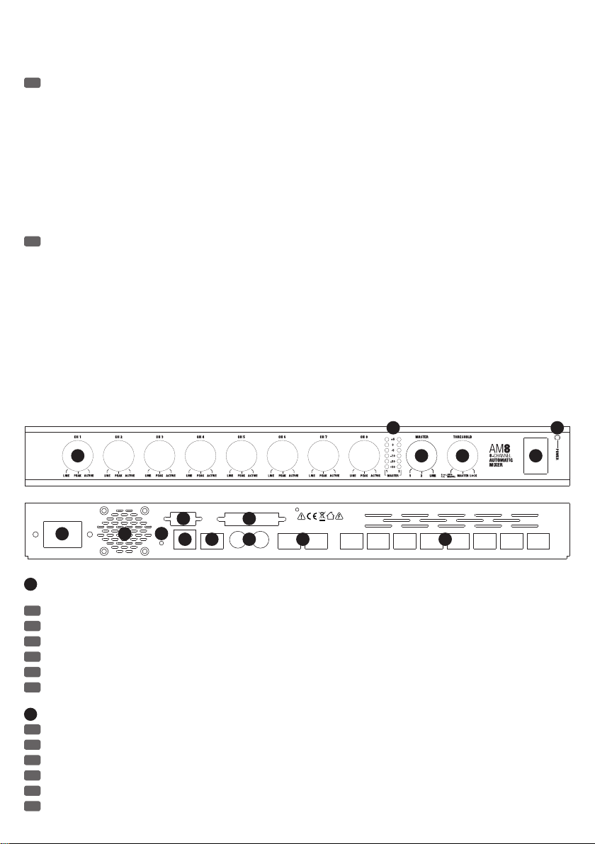
1
SETTING AND DISPLAY ELEMENT CH 1 - CH 8 / EINSTELL- UND ANZEIGEELEMENT CH 1 - CH 8 / RÉGLAGES ET INDICATEURS CANAUX
RS-232
10
9
11 12 14
RESET
NETWORK AES/EBU OUTPUT
+ I - I G
13
EXTERNAL CONTROL
LINK IN LINK OUT MASTER
+ I - I G + I - I G + I - I G + I - I G + I - I G + I - I G + I - I G + I - I G + I - I G + I - I G
OUTPUT 2
CAUTION! DO NOT OPEN RISK OF ELECTRICAL SHOCK !
AVIS! NE PAS OUVRIR RISQUE DE CHOC ELECTRIQUE !
ACHTUNG! NICHT ÖFFNEN, STROMSCHLAGGEFAHR !
15 16
MASTER
CH 8 CH 7 CH 6 CH 5 CH 4 CH 3 CH 2 CH 1
OUTPUT 1
1 À 8 / CONTROLES E INDICADORES CH 1 - CH 8 / REGULATOR I WSKAŹNIK KANAŁÓW 1–8 / CONTROLLI E INDICATORI CH 1 - CH 8
EN
Rotary encoder, push-button and LED display with multi-function.
DE
Drehgeber, Drucktaster und LED-Anzeige mit Mehrfachfunktionen.
FR
Encodeur/sélecteur et couronne LED multifonctions
ES
Control giratorio, pulsador e indicadores LED multifunción.
PL
Pokrętło enkodera przyrostowego, przyciski i wielofunkcyjny wskaźnik diodowy.
IT
Manopole, pulsanti e indicatori LED con funzioni multiple.
2
LED DISPLAYS MASTER 1 & 2
EN
6-segment LED level meter for the sum signals Master 1 and Master 2.
DE
6-Segment Pegel-Anzeigen für die Summensignale Master 1 und Master 2.
FR
Indicateur de niveau sur 6 LED, pour les signaux mixés Master 1 et Master 2
ES
Columnas de 6 LED que indican los niveles de las señales de mezcla Master1 y Master2.
PL
Wskaźniki poziomu sumy sygnałów Master 1 i sumy sygnałów Master 2. Każdy z nich składa się z 6 pojedynczych wskaźników diodowych.
IT
Indicatori di livello a 6 segmenti per i segnali di missaggio Master1 e Master2.
10
· Daimlerstr. 9
is a registered Brand of
®
Page 11

3
SETTING AND DISPLAY ELEMENT MASTER / EINSTELL- UND ANZEIGEELEMENT MASTER / RÉGLAGES ET INDICATEURS CANAUX
MASTER / CONTROL INDICADOR MASTER / REGULATOR I WSKAŹNIK MASTER / CONTROLLI E INDICATORI MASTER
EN
Rotary encoder, push-button and LED display with multi-function.
DE
Drehgeber, Drucktaster und LED-Anzeige mit Mehrfachfunktionen.
FR
Encodeur/sélecteur et couronne LED multifonctions
ES
Control giratorio, pulsador e indicadores LED multifunción.
PL
Pokrętło enkodera przyrostowego, przyciski i wielofunkcyjny wskaźnik diodowy.
IT
Manopole, pulsanti e indicatori LED con funzioni multiple.
4
SETTING AND DISPLAY ELEMENT THRESHOLD / EINSTELL- UND ANZEIGEELEMENT THRESHOLD / RÉGLAGE ET INDICATEUR THRESHOLD /
CONTROL E INDICADOR THRESHOLD / REGULATOR I WSKAŹNIK PROGU / CONTROLLI E INDICATORI THRESHOLD
EN
Rotary encoder, push-button and LED display with multi-function.
DE
Drehgeber, Drucktaster und LED-Anzeige mit Mehrfachfunktionen.
FR
Encodeur/sélecteur et couronne LED multifonctions
ES
Control giratorio, pulsador e indicadores LED multifunción.
PL
Pokrętło enkodera przyrostowego, przyciski i wielofunkcyjny wskaźnik diodowy.
IT
Manopole, pulsanti e indicatori LED con funzioni multiple.
5
POWER
EN
On / Off switch for the power supply of the device.
DE
Ein- / Ausschalter für die Stromzufuhr des Geräts.
FR
Interrupteur d'alimentation de l'appareil.
ES
Interruptor de encendido/apagado del equipo.
PL
Włącznik/Wyłącznik dopływu zasilania do urządzenia.
IT
Interruttore di accensione/spegnimento per l'alimentazione di corrente dell'apparecchio.
6
POWER-LED
EN
The power LED lights up once the system is properly connected to the power mains and switched on.
DE
Die Power-LED leuchtet, wenn das Gerät korrekt am Stromnetz angeschlossen und eingeschaltet ist.
FR
La LED Power s'allume lorsque l'appareil est correctement relié au secteur et sous tension.
ES
El LED POWER se ilumina si el equipo está encendido y correctamente enchufado a la red eléctrica.
PL
Dioda zasilania świeci się, gdy urządzenie jest prawidłowo podłączone do sieci elektrycznej i włączone.
IT
Il LED POWER si accende quando il dispositivo viene correttamente connesso alla rete elettrica e acceso.
7
IEC POWER SOCKET / IEC NETZBUCHSE / EMBASE SECTEUR IEC / TOMA IEC / GNIAZDO SIECIOWE IEC / PRESA DI RETE CEI
EN
Used to power the device. An appropriate power cord is included in the delivery.
DE
Dient der Spannungsversorgung des Geräts. Ein geeignetes Netzkabel befindet sich im Lieferumfang.
FR
Reçoit la tension secteur alimentant l'appareil. Le câble secteur correspondant est livré.
ES
Toma eléctrica para alimentar el equipo. Se suministra con el cable eléctrico apropiado.
PL
Służy do zasilania urządzenia. W zestawie znajduje się odpowiedni kabel sieciowy.
IT
Serve per l'alimentazione di tensione del dispositivo. In dotazione viene fornito un cavo di rete idoneo.
8
HOUSING FAN / GEHÄUSELÜFTER / VENTILATEUR / VENTILADOR / WENTYLATOR OBUDOWY / VENTOLA
9
RESET
EN
When you press the RESET switch, all settings, such as equalizer and routing, are reset to the default settings. Press and hold the switch for
about 6 seconds.
DE
Bei Betätigen des RESET-Tasters werden alle Einstellungen, wie z.B. Equalizer und Routing, auf die Grundeinstellung zurückgesetzt. Halten Sie
den Taster für ca. 6 Sekunden gedrückt.
FR
Lorsque vous appuyez sur la touche RESET, tous les réglages sont réinitialisés à leurs valeurs de départ : égaliseurs, assignations... Maintenez
enfoncée la touche pendant environ 6 secondes.
ES
Pulse RESET para restablecer todos los ajustes del equipo (ecualizador y envíos) a la configuración por defecto. Manténgalo pulsado durante
6segundos aproximadamente.
11
Page 12

PL
Po naciśnięciu przycisku RESET wszystkie ustawienia, takie jak np. ustawienia korektora dźwięku i trasowania, zostaną przywrócone do
wartości fabrycznych. Nacisnąć i przytrzymać przycisk RESET przez ok. 6 sekund.
IT
Premendo il tasto RESET, tutte le impostazioni, quali ad esempio equalizzatore e instradamento, vengono ripristinate alla configurazione default.
Tenere premuto il tasto per circa 6secondi.
10
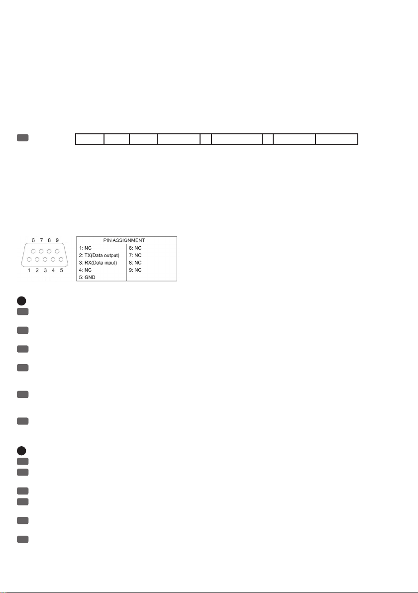
RS-232 INTERFACE / RS-232 SCHNITTSTELLE / PORT RS-232 / PUERTO RS-232 / INTERFEJS RS-232 / PORTA RS-232
EN
Settings:
Command settings:
RS-232 commands (16 HEX ASCII):
%V, +device address (1 bit), +8 channels volume (8 bit), +master volume (2 bit), +manual threshold level (1 bit), +CRC +#
device address (1 bit): device 1-16, 1 for the master device
channel volume (8 bit): channel 1-8, 0-60 dB, in steps of 1 dB
master volume (2 bit): master volume 1/2, 0-60 dB, in steps of 1dB.
manual threshold level (1 bit): 0-60 dB, in steps of 4 dB.
Example:
%V,01,2020202020202020,3030,0A,AF79#
RS-232 Baud: 115200 Data: 8 Stop: 1 Parity: None
DE
Einstellungen:
Steuerbefehle:
RS-232 commands (16 HEX ASCII):
%V, +device address (1 bit), +8 channels volume (8 bit), +master volume (2 bit), +manual threshold level (1 bit), +CRC +#
device address (1 bit): device 1-16, 1 for the master device
channel volume (8 bit): channel 1-8, 0-60dB, in steps of 1dB
master volume (2 bit): master volume 1/2, 0-60 dB, in steps of 1dB.
manual threshold level (1 bit): 0-60dB, in steps of 4dB.
Example:
%V,01,2020202020202020,3030,0A,AF79#
FR
Réglages :
Protocole de commande :
Commandes RS-232 (16 HEX ASCII)
%V, + adresse appareil (1 bit), + volume 8 canaux (8 bits), +volume Master (2 bits), + niveau de seuil manuel (1 bit), +CRC +#
adresse appareil (1 bit) : appareil 1-16, 1 pour l'appareil Master
volume canal (8 bits) : canal 1 à 8, 0 à 60 dB, par pas de 1 dB
volume Master (2 bits) : volume Master 1/2, 0 à 60 dB, par pas de 1 dB.
niveau de seuil manuel (1 bit) : 0 à 60 dB, par pas de 4 dB.
Exemple :
%V,01,2020202020202020,3030,0A,AF79#
ES
Configuración:
Comandos de control:
Comandos RS-232 (16 HEX ASCII):
%V, +dirección dispositivo (1bit), + volumen de 8 canales (8bits), + volumen master (2bits), + nivel manual de umbral (1bit), +CRC +#
Dirección dispositivo (1bit): dispositivo 1 - 16, 1 para el dispositivo master.
Volumen de canal (8bits): canal 1 - 8, 0 - 60dB, en pasos de 1dB.
Volumen master (2bits): volumen master 1 - 2, 0 - 60dB, en pasos de 1dB.
Nivel de umbral manual (1 bit): 0 - 60 dB, en pasos de 4dB.
Ejemplo:
%V,01,2020202020202020,3030,0A,AF79#
RS-232 Baud: 115200 Data: 8 Stop: 1 Parity: None
RS-232 Bauds : 115200 Bits Data : 8 Bit Stop : 1 Bit Parité : Aucun
RS-232 Velocidad: 115.200 Bits de datos: 8 Bits de parada: 1 Bits de paridad: Ninguno
PL
Ustawienia:
Polecenia sterujące:
Polecenia interfejsu RS-232 (16 HEX ASCII):
%V, +device address (1 bit), +8 channels volume (8 bit), +master volume (2 bit), +manual threshold level (1 bit), +CRC +#
RS-232 Bod: 115200 Dane: 8 Stop 1 Parzystość: brak
12
Page 13
[%V, +adres urządzenia (1 bit), +8 kanałów – głośność (8 bit), +głośność master (2 bit), +ręczny poziom progu (1 bit), +CRC +#]
device address (1 bit): device 1–16, 1 for the master device
[adres urządzenia (1 bit): urządzenie 1–16, 1 dla urządzenia głównego]
channel volume (8 bit): channel 1–8, 0–60 dB, in steps of 1 dB
[głośność kanału (8 bit): kanał 1–8, 0–60 dB, w krokach co 1 dB]
master volume (2 bit): master volume 1/2, 0–60 dB, in steps of 1 dB.
[głośność master (2 bit): głośność master 1/2, 0–60 dB, w krokach co 1 dB].
manual threshold level (1 bit):
[ręczny poziom progu (1 bit)]: 0–60 dB, w krokach co 4 dB.
Przykład:
%V,01,2020202020202020,3030,0A,AF79#
IT
Impostazioni:
Comandi:
Comandi RS-232 (16 HEX ASCII):
%V, + indirizzo dispositivo (1 bit), + volume 8canali (8bit), + volume master (2bit), + livello soglia manuale (1 bit), + CRC +#
dispositivo indirizzo (1bit): dispositivo 1-16, 1 per dispositivo master
volume canale (8bit): canali 1-8, 0-60dB, in passi di 1dB
volume master (2bit): volume master 1-2, 0-60dB, in passi di 1dB.
livello di soglia manuale (1bit): 0-60dB, in passi di 4dB.
Esempio:
%V,01,2020202020202020,3030,0A,AF79#
11
NETWORK
EN
The RS485 interface allows the remote control of the AM8 automatic mixer through a Windows PC (control software AUTOMIX8 included).
Connect the AM8 automatic mixer with the Ethernet interface of the computer using a CAT-5 LAN cable.
DE
Die RS485 Schnittstelle ermöglicht die Fernsteuerung des AM8 Automatik-Mixers durch einen Windows-PC (Kontroll-Software AUTOMIX8 im
Lieferumfang). Verbinden Sie den AM8 Automatik-Mixer mit der Ethernet-Schnittstelle des Rechners mit Hilfe eines CAT-5 LAN-Kabels.
FR
Le port réseau RS-485 permet le pilotage à distance du mixeur automatique AM8 via un PC sous Windows (avec le logiciel de contrôle
AUTOMIX8). Reliez le mixeur automatique AM8 au port Ethernet à l'aide d'un câble réseau CAT-5.
ES
El puerto RS-485 permite controlar de forma remota el mezclador automático AM8 a través de un ordenador con sistema operativo Windows
(se suministra el programa de control AUTOMIX8). Conecte el puerto Ethernet del mezclador automático AM8 con el ordenador mediante un cable
CAT-5.
PL
Interfejs RS485 umożliwia zdalne sterowanie automatycznym mikserem typu Matrix za pomocą komputera z systemem operacyjnym Windows
(oprogramowanie sterujące AUTOMIX8 znajduje się w zestawie). Podłączyć automatyczny mikser AM8 do złącza Ethernet komputera za pomocą
kabla LAN CAT-5.
IT
La porta RS-485 consente di controllare in remoto il mixer automatico AM8 attraverso un PC con sistema operativo Windows (software di
controllo AUTOMIX8 fornito in dotazione). Collegare il mixer automatico AM8 con la porta Ethernet del computer utilizzando un cavo CAT-5 LAN.
RS-232 Baud: 115.200 Bit di dati: 8 Bit di arresto: 1 Bit di parità: Nessuno
12
AES/EBU OUTPUT
EN
Terminal block connector for the output of the sum signal in the digital AES/EBU format (terminal block included, configuration as shown).
DE
Klemmblock-Anschluss für die Ausgabe des Summen-Signals im digitalen AES/EBU Format (Klemmblock im Lieferumfang, Belegung wie
abgebildet).
FR
Connexion sur Phoenix pour sortie du signal mixé au format numérique AES/EBU (connecteur Phoenix livré, mise en place comme illustré).
ES
Bloque de terminales para la salida de la señal de mezcla en formato digital AES/EBU (se suministra la regleta de terminales; se indica la
disposición de pines).
PL
Złącze na kostkę zaciskową do wyprowadzenia sumy sygnałów w cyfrowym formacie AES/EBU (kostka zaciskowa znajduje się w zestawie,
skojarzenie przyłączy zgodne z przedstawionym).
IT
Collegamento della morsettiera per l'uscita del segnale di missaggio nel formato digitale AES/EBU (morsettiera fornita in dotazione,
configurazione dei pin come illustrato in figura).
13
Page 14

13
EXTERNAL CONTROL
EN
The D-SUB 25-pin interface offers the possibility of external control of the input channels (CH input). There is a 3.3 V DC voltage at the outputs
1 to 8 (CH output) for controlling external devices, once a channel is activated.
DE
Die D-SUB 25-Pin Schnittstelle bietet die Möglichkeit der externen Kontrolle über die Eingangs-Kanäle (CH Input). An den Ausgängen 1 bis 8
(CH Output) liegt eine 3,3V Gleichspannung für die Kontrolle externer Geräte an, sobald ein Kanal aktiviert wird.
FR
Le port Sub-D 25 points offre la possibilité d'un contrôle externe sur les canaux d'entrée (CH Input). Sur les sorties 1 à 8 (CH Output) se trouve
une tension continue de 3,3 V pour le contrôle d'appareils externes, dès qu'un canal est activé.
ES
Conector D-Sub de 25pines para controlar externamente los canales de entrada CH. En las salidas CH1 a 8 hay una tensión continua de
3,3voltios para poder controlar equipos externos en cuanto se activa un canal.
PL
25-pinowy interfejs D-SUB daje możliwość zewnętrznego sterowania kanałami wejściowymi (CH Input/wejście kanału) Wyjścia kanałów od 1
do 8 (CH Output/wyjście kanału) charakteryzują się stałym napięciem o wartości 3,3 V, co umożliwia sterowanie urządzeniami zewnętrznymi.
Napięcie na danym kanale pojawia się zaraz po jego włączeniu.
IT
Il connettore D-Sub a 25pin consente il controllo esterno tramite i canali di ingresso (CH). Sulle uscite da 1 8 è presente una corrente continua
da 3,3V per il controllo delle apparecchiature esterne non appena si attiva un canale.
25-Pin D-SUB connector pin assignment
Pin 1: Ground Pin 14: Ground
Pin 2: Ground Pin 15: Empty
Pin 3: Ground Pin 16: Empty
Pin 4: Ground Pin 17: Empty
Pin 5: Empty Pin 18: CH1 Input (short-to-ground activates channel)
Pin 6: CH1 Output (3,3V when channel is activated) Pin 19: CH2 Input (short-to-ground activates channel)
Pin 7: CH2 Output (3,3V when channel is activated) Pin 20: CH3 Input (short-to-ground activates channel)
Pin 8: CH3 Output (3,3V when channel is activated) Pin 21: CH4 Input (short-to-ground activates channel)
Pin 9: CH4 Output (3,3V when channel is activated) Pin 22: CH5 Input (short-to-ground activates channel)
Pin 10: CH5 Output (3,3V when channel is activated) Pin 23: CH6 Input (short-to-ground activates channel)
Pin 11: CH6 Output (3,3V when channel is activated) Pin 24: CH7 Input (short-to-ground activates channel)
Pin 12: CH7 Output (3,3V when channel is activated) Pin 25: CH8 Input (short-to-ground activates channel)
Pin 13: CH8 Output (3,3V when channel is activated)
14
LINK IN / LINK OUT
EN
Mini DIN connectors to daisy-chain up to 16 AM8 automatic mixers (1 mini DIN connection cable per device included). The audio inputs of all
slave units of the AM8 automatic mixer in the system, will be routed to the line outputs Master 1 and Master 2 of the master unit.
DE
Mini-DIN Anschlüsse zum Kaskadieren von bis zu 16 AM8 Automatik-Mixern (1 Mini-DIN Verbindungskabel pro Gerät im Lieferumfang). Die
Audio-Eingänge aller Slave-Einheiten des AM8 Automatik-Mixers im System, werden hierbei auf die Line-Ausgänge Master 1 und Master 2 der
Master-Einheit geroutet.
FR
Connecteurs Mini-DIN pour cascade d'un maximum de 16 mixeurs automatiques AM8 (chaque appareil est livré avec 1 câble Mini-DIN). Les
entrées audio de tous les appareils esclaves dans un système composé de plusieurs mixeurs automatiques AM8 sont alors assignées aux sorties
ligne Master 1 et Master 2 de l'appareil Master.
ES
Conector mini-DIN para poner en cascada hasta 16mezcladores automáticos AM8 (en cada equipo se suministra 1cable con conectores
mini-DIN). Las entradas de audio de todos los mezcladores esclavos AM8 del sistema tienen las salidas de línea Master1 y Master2 del mezclador
maestro.
PL
Złącza Mini-DIN służące do kaskadowania maksymalnie 16 automatycznych mikserów AM8 (1 kabel Mini-DIN znajduje się w zestawie). Dzięki
nim wejścia audio wszystkich jednostek automatycznego miksera AM8 pracujących w systemie w trybie urządzeń podporządkowanych (slave) będą
przetrasowywane na wyjścia liniowe Master 1 i Master 2 jednostki głównej (master).
IT
Connettori mini DIN per collegare a cascata fino a 16mixer automatici AM8 (1cavo di collegamento mini DIN fornito in dotazione con ogni
apparecchio). Gli ingressi audio di tutte le unità slave del mixer automatico AM8 del sistema sono instradati nelle uscite di linea Master1 e Master2
dell'unità master.
15
MASTER OUTPUT 1 + 2
EN
Balanced line outputs Master 1 and 2 with terminal block connector (terminal block included, configuration as shown). The volume of both line
outputs can be individually adjusted (see point 23).
DE
Symmetrische Line-Ausgänge Master 1 und 2 mit Klemmblock-Anschlüssen (Klemmblöcke im Lieferumfang, Belegung wie abgebildet). Die
Lautstärke beider Line-Ausgänge kann individuell eingestellt werden (siehe Punkt 23).
14
Page 15

FR
Sorties ligne symétriques Master 1 et 2 sur Phoenix (connecteur Phoenix livré, mise en place comme illustré). Le niveau de ces sorties se règle
indépendamment (voir Point 23).
ES
Salidas de línea balanceadas Master1 y 2 con bloques de terminales (se suministran bloques de terminales; se indica la disposición de pines).
Se puede ajustar el nivel de las dos salidas de línea de forma independiente (ver punto23).
PL
Symetryczne wyjścia liniowe Master 1 i 2 zostały przystosowane do podłączenia kostek zaciskowych (kostki zaciskowe znajdują się w
zestawie, skojarzenie przyłączy zgodne z przedstawionym). Głośności obu wyjść liniowych mogą zostać ustawione niezależnie od siebie (patrz punkt
23).
IT
Uscite di linea bilanciate Master1 e 2 con morsettiera (morsettiere fornite in dotazione, configurazione dei pin come illustrato). Il volume può
essere impostato separatamente per le due uscite di linea (v.punto23).
16
INPUT CH 1 - CH 8
EN
Balanced microphone or line inputs of channels 1 to 8 with terminal block connector (terminal block included, configuration as shown).
DE
Symmetrische Mikrofon-, bzw. Line-Eingänge der Kanäle 1 bis 8 mit Klemmblock-Anschlüssen (Klemmblöcke im Lieferumfang, Belegung wie
abgebildet).
FR
Entrées Micro/Ligne symétriques des canaux 1 à 8 sur Phoenix (connecteur Phoenix livré, mise en place comme illustré).
ES
Entradas de micro o línea balanceadas de los canales1 a 8 con bloques de terminales (se suministra la regleta de terminales; se indica la
disposición de pines).
PL
Symetryczne wejście mikrofonowe/liniowe kanałów od 1 do 8 zostały przystosowane do podłączenia kostek zaciskowych (kostki zaciskowe
znajdują się w zestawie, skojarzenie przyłączy zgodne z przedstawionym).
IT
Ingressi di linea o di microfono bilanciati dei canali da 1 a 8 con morsettiera (morsettiere fornite in dotazione, configurazione dei pin come
illustrato).
MANUAL OPERATION / MANUELLE BEDIENUNG / UTILISATION MANUELLE / OPERACIÓN MANUAL /
OBSŁUGA RĘCZNA / FUNZIONAMENTO MANUALE
18
17
19
20 22
21
17
INPUT GAIN CH 1 - CH 8 / EINGANGSVORVERSTÄRKUNG CH 1 - CH 8 / PRÉAMPLIS CH 1 - CH 8 / GANANCIA DE ENTRADA CH 1 - CH 8
/ WSTĘPNE WZMOCNIENIE WEJŚCIA KANAŁÓW 1–8 / PREAMPLIFICAZIONE INGRESSO CH 1 - CH 8
EN
Rotary encoder for setting the input gain. Turning it to the right increases and turning it to the left reduces the input gain (please observe LED
indicator N°18)
DE
Drehgeber für die Einstellung der Eingangsvorverstärkung. Drehung nach rechts erhöht die Eingangsvorverstärkung, Drehung nach links
verringert sie (LED-Anzeige Nr. 18 beachten).
FR
Encodeur de réglage du préampli d'entrée Tournez-le vers la droite pour augmenter le gain, vers la gauche pour le réduire (surveiller la
couronne de LED n°18).
ES
Control giratorio para ajustar la ganancia de entrada. Gírelo a la derecha para aumentar la ganancia de entrada, o a la izquierda para
disminuirla (corona de LED18).
PL
Pokrętło enkodera przyrostowego do ustawiania wstępnego wzmocnienia wejścia. Obrót w prawo zwiększa, a obrót w lewo zmniejsza wstępne
wzmocnienie wejścia (zwrócić uwagę na wskaźnik diodowy nr 18).
IT
Manopola per l'impostazione della preamplificazione d'ingresso. Ruotando verso destra si aumenta la preamplificazione, verso sinistra si riduce
(osservare l'indicatore LED n.18).
18
LED DISPLAY CH 1 - CH 8 / LED-ANZEIGE CH 1 - CH 8 / COURONNE LED CH 1 - CH 8 / CORONA DE LED CH 1 - CH 8 / WSKAŹNIK
DIODOWY KANAŁÓW 1–8 / INDICATORE LED CH 1 - CH 8
EN
15-segment LED display for the visualisation of the gain input setting.
DE
15-Segment LED-Anzeige für die Visualisierung der Einstellung der Eingangsvorverstärkung.
FR
Couronne de 15 LED pour visualisation du niveau du signal d'entrée
ES
Corona LED de 15segmentos para indicar el ajuste de ganancia de entrada.
PL
Składający się z 15 diod wskaźnik, który w jasny i widoczny sposób informuje o ustawieniu wstępnego wzmocnienia wejścia.
IT
Indicatore LED a 15 segmenti per la visualizzazione dell'impostazione della preamplificazione d'ingresso.
15
Page 16

19
PUSH-BUTTON CH 1 - CH 8 / DRUCKTASTER CH 1 - CH 8 / ENCODEUR/TOUCHE CH 1 - CH 8 / PULSADOR CH 1 - CH 8 / PRZYCISKI
KANAŁÓW 1–8 / PULSANTE CH 1 - CH 8
EN
Input sensitivity - to switch an input from microphone to line sensitivity, and vice versa, press the push button of the rotary encoder of the
corresponding channel. The round LED above the lettering "LINE" starts to flash red. If you press again on the push-button, the input sensitivity is
switched over (see table "LINE / MIC STATUS LED"). If the push-button is not pressed within 10 seconds, there will be no change and the LED stops
flashing. Channel priority – to assign priority to a channel, first press the push-button of the rotary encoder, if necessary, turn the encoder until the
status LED ACTIVE flashes red and now press the push-button again. The status LED ACTIVE now lights up red permanently. If the push-button is not
pressed within 10 seconds, there will be no change and the LED stops flashing.
DE
Eingangsempfindlichkeit - Um einen Eingang von Mikrofon- auf Line-Empfindlichkeit umzuschalten und umgekehrt, drücken Sie auf den
Drucktaster des Drehgebers des entsprechenden Kanals. Die runde LED über dem Schriftzug "LINE" beginnt rot zu blinken. Drücken Sie abermals
auf den Drucktaster, wird die Eingangsempfindlichkeit umgeschaltet (siehe Tabelle "LINE / MIC STATUS-LED"). Wird der Drucktaster innerhalb von ca.
10 Sekunden nicht betätigt, erfolgt keine Änderung und das Blinken der LED stoppt. Kanal-Priorität - Um einem Kanal Priorität zuzuweisen,
betätigen Sie zunächst den Drucktaster des Drehgebers, drehen gegebenenfalls den Drehgeber so weit, bis die Status-LED ACTIVE rot blinkt und
betätigen nun abermals den Drucktaster des Drehgebers. Die Status-LED ACTIVE leuchtet nun permanent rot. Wird der Drucktaster innerhalb von ca.
10 Sekunden nicht betätigt, erfolgt keine Änderung und das Blinken der LED stoppt.
FR
Sélecteur de sensibilité d'entrée - Pour faire passer une entrée du niveau micro au niveau ligne et inversement, appuyez sur l'encodeur du
canal correspondant. La LED ronde correspondant à l'inscription "LINE" se met à clignoter en rouge. Appuyez de nouveau sur l'encodeur : la
sensibilité d'entrée est alors modifiée (voir "INDICATEUR LED LINE / MIC" ci-après). Si vous n'appuyez pas de nouveau sur l'encodeur dans les 10
secondes, la sensibilité n'est pas modifiée et la LED s'arrête de clignoter. Priorité de canal - Pour attribuer la priorité à un canal, appuyez d'abord
sur l'encodeur, puis tournez-le jusqu'à ce que l'indicateur LED ACTIVE clignote en rouge ; appuyez alors de nouveau sur l'encodeur. L'indicateur LED
ACTIVE reste alors allumée en rouge. Si vous n'appuyez pas de nouveau sur l'encodeur dans les 10 secondes, aucune modification n'intervient, et la
LED s'arrête de clignoter.
ES
Sensibilidad de entrada: para cambiar la sensibilidad entre micrófono y línea de una entrada, pulse el control giratorio del canal
correspondiente. El LED encima de «LINE» empezará a parpadear en color rojo. Pulse de nuevo el control giratorio para cambiar la sensibilidad de
entrada (ver tabla «LED DE ESTADO LÍNEA/MICRO»). Tenga en cuenta que si no pulsa el control giratorio en 10segundos, no se introducirá ningún
cambio y el LED dejará de parpadear. Canal de prioridad: para asignar la prioridad a un canal, primero pulse el control giratorio, si es necesario
gire el control giratorio hasta que el LED de estado ACTIVE parpadee en color rojo, y pulse de nuevo el control giratorio. El LED de estado ACTIVE
permanecerá encendido de color rojo. Tenga en cuenta que si no pulsa el control giratorio en 10segundos, no se introducirá ningún cambio y el LED
dejará de parpadear.
PL
Czułość wejścia. W celu przełączenia i zmiany czułości wejścia z odpowiedniej dla sygnału mikrofonowego na właściwą dla sygnału
liniowego należy nacisnąć przycisk pokrętła enkodera przyrostowego odpowiedniego kanału. Okrągła dioda znajdująca się nad napisem „LINE”
zacznie pulsować na czerwono. Ponowne naciśnięcie przycisku pokrętła enkodera przyrostowego spowoduje przestawienie czułości wejścia – patrz
Tabela „DIODA STANU SYGNAŁU LINIOWEGO/MIKROFONOWEGO)”. Jeżeli przycisk nie zostanie naciśnięty w ciągu ok. 10 sekund, żadne zmiany nie
nastąpią, a dioda przestanie pulsować. Priorytet kanału. W celu przydzielenia priorytetu kanału najpierw należy nacisnąć przycisk pokrętła
enkodera przyrostowego i przekręcić pokrętło tak mocno, aż dioda stanu aktywnego kanału („ACTIVE”) zacznie pulsować na czerwono, a następnie
nacisnąć tylko ponownie przycisk pokrętła enkodera przyrostowego. Od teraz dioda stanu będzie świecić ciągłym czerwonym światłem. Jeżeli
przycisk pokrętła nie zostanie naciśnięty w ciągu ok. 10 sekund, żadne zmiany nie nastąpią, a dioda przestanie pulsować.
IT
Sensibilità di ingresso - Per cambiare la sensibilità di un ingresso da microfono a linea e viceversa, premere il tasto della manopola del
canale corrispondente. Il LED visibile sopra la scritta "LINE" inizia a lampeggiare in rosso. Premere brevemente il tasto per commutare la sensibilità
di ingresso (v. tabella "LED DI STATO LINEA/MICROFONO"). Se il tasto non viene premuto entro una decina di secondi, la sensibilità non cambia e il
LED smette di lampeggiare. Priorità del canale - Per assegnare la priorità a un canale, premere innanzitutto la manopola, eventualmente ruotarla
fino a quando il LED di stato ACTIVE lampeggia in rosso, quindi premerla brevemente. Il LED di stato ACTIVE ora resta acceso in rosso. Se il tasto non
viene premuto entro una decina di secondi, la sensibilità non cambia e il LED smette di lampeggiare.
20
STATUS-LED LINE / MIC CH 1 - CH 8
EN
The status LED indicates the input sensitivity of each channel CH 1 to CH 8 (see point 19).
DE
Die Status-LED zeigt die Einstellung der Eingangsempfindlichkeit des jeweiligen Kanals CH 1 bis CH 8 an (siehe Punkt 19).
FR
Cet indicateur LED indique la sensibilité d'entrée sur chacun des canaux, de CH 1 à CH 8 (voir Point 19).
ES
El LED de estado indica la sensibilidad de entrada de cada uno de los canales CH1 a 8 (ver punto19).
PL
Dioda stanu informuje o ustawieniu czułości wejścia danego kanału, tj. od 1 do 8 (patrz punkt 19).
IT
Il LED di stato indica l'impostazione della sensibilità d'ingresso dei vari canali da CH1 a CH8 (v.punto19).
16
Page 17
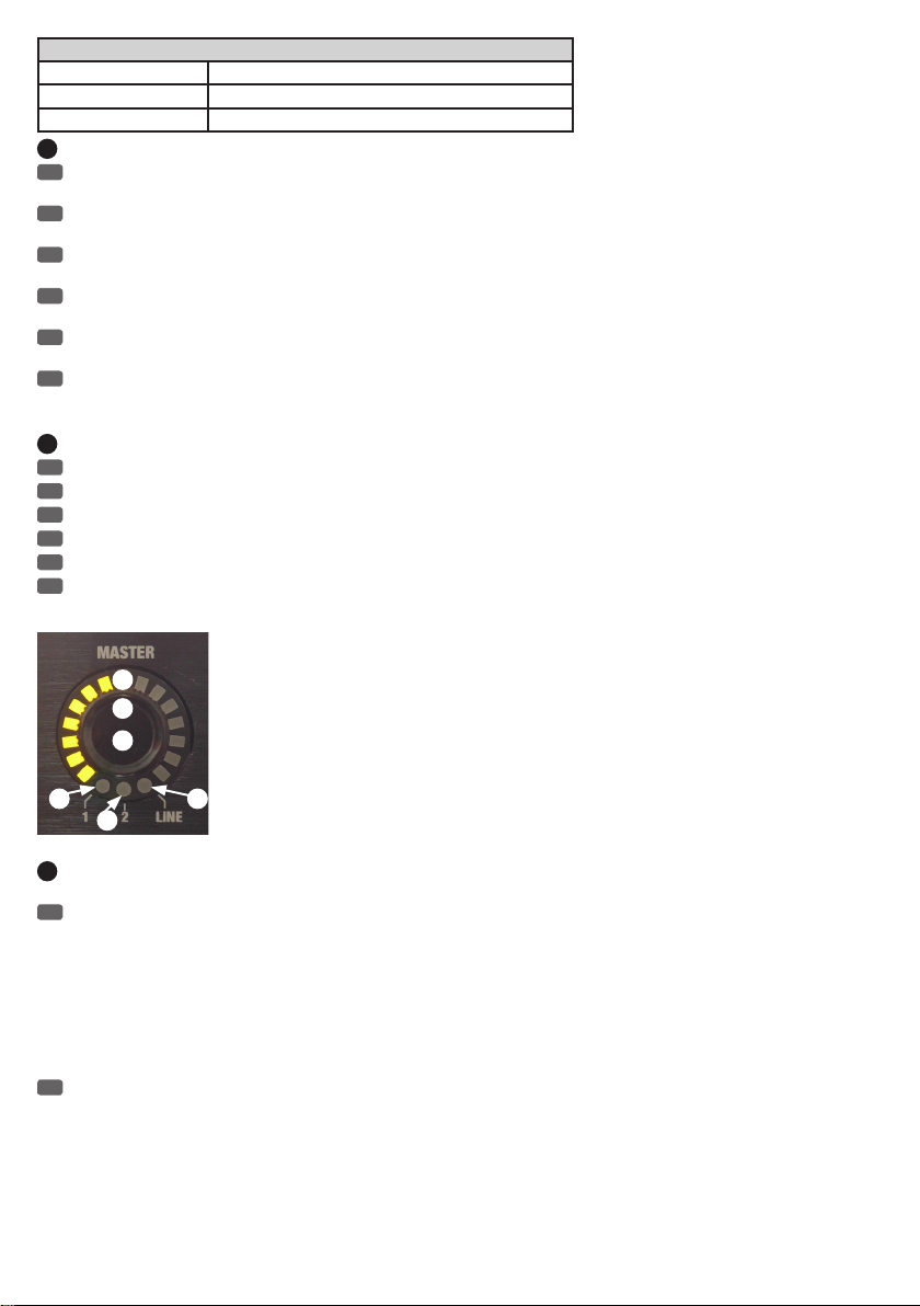
STATUS LED LINE / MIC
LED flashing red: ready to switch
LED green Line sensitivity, 48 V phantom power disabled
LED off Microphone sensitivity, 48 V phantom power activated
21
PEAK-LED CH 1 - CH 8
EN
Once the PEAK LED lights up red, the corresponding channel is operating at the distortion limit. To avoid distortion, reduce the input gain using
the rotary encoder (see point 17).
DE
Leuchtet die rote PEAK-LED auf, wird der entsprechende Kanal an der Verzerrungsgrenze betrieben. Um Verzerrungen zu vermeiden, reduzieren
Sie die Eingangsvorverstärkung mit Hilfe des Drehgebers (siehe Punkt 17).
FR
Dès que la LED rouge PEAK s'allume, c'est que les étages électroniques du canal d'entrée correspondant travaillent à la limite de la saturation.
Pour éviter toute distorsion, réduisez le gain sur l'entrée, via l'encodeur (voir Point 17).
ES
El LED PEAK se ilumina de color rojo cuando el canal está saturando. Para no saturar, use el control giratorio para disminuir la ganancia de
entrada (ver punto17).
PL
Gdy zaświeci się czerwona dioda wartości szczytowej, oznacza to, że dany kanał pracuje na granicy zniekształceń. Aby uniknąć zniekształceń,
należy zredukować poziom wstępnego wzmocnienia wejścia za pomocą pokrętła enkodera przyrostowego (patrz punkt 17).
IT
Se il LED PEAK è acceso in rosso, il canale corrispondente funziona al limite di distorsione. Per evitare distorsioni, ridurre la preamplificazione
d'ingresso con la manopola (v.punto17).
22
ACTIVE-LED CH 1 - CH 8
EN
The ACTIVE LED indicates which of the 8 channels of the automatic mixer is currently active.
DE
Die ACTIVE-LED zeigt an, welcher der 8 Kanäle des Automatik-Mixers aktuell aktiv ist.
FR
La LED ACTIVE indique les canaux actuellement activés parmi les 8 du mixeur automatique.
ES
El LED ACTIVE indica cuál de los 8canales del mezclador automático es el canal activo.
PL
Dioda aktywnego kanału informuje, który z 8 kanałów automatycznego miksera jest w danym momencie aktywny.
IT
Il LED ACTIVE indica quale degli 8canali del mixer automatico è attivo attualmente.
24
23
25
27
23
SUM VOLUME MASTER 1 + 2 / SUMMENLAUTSTÄRKE MASTER 1 + 2 / VOLUME BUS MASTER 1 + 2 / NIVEL DE MEZCLA MASTER 1 + 2 /
SUMA GŁOŚNOŚCI MASTER 1 + 2 / VOLUME DI MISSAGGIO MASTER 1 + 2
EN
Encoder for setting the total volume of the line outputs Master 1 and Master 2 (dual function). If the display LED 1 lights up green (N°26), the
sum volume of the line output Master 1 can be adjusted as desired using the MASTER rotary encoder. If the display LED 2 lights up green (N°27), the
same applies to the line output Master 2. Turning it to the right increases the volume and turning it to the left reduces it.
To adjust the volume, select the line outputs Master 1 or Master 2 by first pressing the push-button of the MASTER rotary encoder. Now, while the
LED display of the currently selected line output from Master 1 (N°26) or Master 2 (N°27) flashes red, select the other line output for adjusting the
total volume using the MASTER rotary encoder. Confirm the selection by pressing the push-button on the MASTER rotary encoder. By combining the
two output channels Master 1 and 2 in a channel group (see CHANNEL GROUPS), the volume of both channels can be set simultaneously using the
MASTER rotary encoder.
DE
Drehgeber für die Einstellung der Summenlautstärke der Line-Ausgänge Master 1 und Master 2 (Doppelfunktion). Leuchtet die Anzeige-LED 1
grün (Nr. 26), kann die Summenlautstärke des Line-Ausgangs Master 1 wunschgemäß mit Hilfe des Drehgebers MASTER eingestellt werden, leuchtet
die Anzeige-LED 2 grün (Nr. 27), die des Line-Ausgangs Master 2. Drehung nach rechts erhöht die Lautstärke, Drehung nach links verringert sie.
Wählen Sie die Line-Ausgänge Master 1 oder Master 2 für die Lautstärkeneinstellung aus, indem Sie zuerst den Drucktaster des Drehgebers MASTER betätigen. Während nun die Anzeige-LED des aktuell ausgewählten Line-Ausgangs Master 1 (Nr. 26) oder Master 2 (Nr. 27) rot blinkt, wählen
Sie mit Hilfe des Drehgebers MASTER den jeweils anderen Line-Ausgang für die Einstellung der Summenlautstärke aus. Bestätigen Sie den Vorgang
durch Drücken auf den Drucktaster MASTER. Durch Zusammenfassen der beiden Ausgangs-Kanäle Master 1 und 2 in einer Kanal-Gruppe (siehe
KANAL-GRUPPEN), kann die Lautstärke beider Kanäle simultan mit Hilfe des Drehgebers MASTER eingestellt werden.
2826
17
Page 18

FR
Cet encodeur sert à régler le niveau de sortie ligne des bus Master 1 et Master 2 (double fonction) Si la LED 1 est allumée en vert (n°26),
l'encodeur MASTER sert à régler le niveau de la sortie ligne du bus Master 1 ; si c'est la LED 2 qui est allumée (27), il sert à régler le niveau de la
sortie ligne du bus Master 2. Tourner vers la droite augmente le volume, tourner vers la gauche le réduit.
Pour choisir le bus Master 1 ou Master 2 pour le réglage, appuyez sur l'encodeur MASTER. L'indicateur LED correspondant à la sortie ligne actuellement choisie s'allume, Master 1 (n°26) ou Master 2 (n°27). Tournez alors l'encodeur pour passer au réglage de l'autre sortie ligne. Validez ensuite
votre choix en appuyant sur l'encodeur MASTER. En jumelant les deux canaux de sortie Master 1 et 2 au sein d'un groupe de canaux (voirGROUPES
DE CANAUX), vous pouvez régler simultanément le niveau sur les deux canaux simultanément via l'encodeur MASTER.
ES
Control giratorio para ajustar el nivel de mezcla de las salidas de línea Master1 y Master2 (doble función). Si el LED1 (26) se ilumina de color
verde, el control giratorio MASTER regulará el nivel de mezcla de la salida de línea Master1; si el LED2 (27) se ilumina de color verde, se regulará el
nivel de mezcla de la salida de línea Master2. Gírelo a la derecha para aumentar el nivel, o a la izquierda para bajarlo.
Para elegir si ajustar el nivel de la salida de línea Master1 o Master2, pulse primero el control giratorio MASTER. Mientras el LED de la salida de
línea actualmente seleccionada, Master1 (26) o Master2 (27) parpadea en color rojo, seleccione la otra salida de línea con el control giratorio
MASTER para poder ajustar el nivel de mezcla. Confirme la operación pulsando el control giratorio MASTER. Al agrupar los dos canales de salida
Master1 y 2 en un grupo de canales (ver GRUPOS DE CANALES), el nivel de ambos canales se puede regular simultáneamente mediante el control
giratorio MASTER.
PL
Pokrętło enkodera przyrostowego do ustawiania sumy głośności wyjść liniowych Master 1 i Master 2 (funkcja podwójna). Kiedy wskaźnik
diodowy 1 świeci się na zielono (nr 26), możliwe jest ustawienie według własnego uznania sumy głośności wyjścia liniowego Master 1 za pomocą
pokrętła enkodera przyrostowego MASTER. Natomiast jeżeli wskaźnik diodowy 2 świeci się na zielono, możliwa jest zmiana ustawienia dla wyjścia
liniowego Master 2. Obrót w prawo zwiększa, a obrót w lewo zmniejsza głośność.
Wybrać wyjście liniowe Master 1 lub Master 2 w celu ustawienia jego głośności poprzez naciśnięcie w pierwszej kolejności przycisku pokrętła enkodera przyrostowego MASTER. Podczas gdy wskaźnik diodowy aktualnie wybranego wyjścia liniowego Master 1 (nr 26) lub Master 2 (nr 27) pulsuje
na czerwono, istnieje możliwość wybrania drugiego wyjścia liniowego w celu ustawienia sumy głośności tego wyjścia za pomocą pokrętła enkodera
przyrostowego MASTER. Potwierdzić zmianę ustawień przez naciśnięcie przycisku MASTER. W przypadku przypisania obu kanałów wyjściowych
Master 1 i Master 2 do jednej grupy kanałów (patrz GRUPY KANAŁÓW) można jednocześnie ustawić głośność obu z nich za pomocą pokrętła
enkodera przyrostowego MASTER.
IT
Manopola per l'impostazione del volume di missaggio delle uscite di linea Master1 e Master2 (doppia funzione). Se l'indicatore LED1 (n.26)
si accende in verde, con la manopola MASTER è possibile impostare il volume di missaggio dell'uscita di linea Master1; se l'indicatore LED2 (n.27)
si accende in verde, si può impostare il volume di missaggio dell'uscita di linea Master2. Girando a destra si aumenta il volume, a sinistra si
abbassa. Selezionare le uscite di linea Master1 o Master2 per l'impostazione volume premendo innanzitutto la manopola MASTER. Mentre ora
l'indicatore LED dell'uscita di linea attualmente selezionata Master1 (n.26) o Master2 (n.27) lampeggia in rosso, utilizzare la manopola MASTER
per selezionare l'altra uscita di linea per impostare il volume di missaggio. Confermare la procedura premendo il tasto MASTER. Raggruppando i
canali delle due uscite Master1 e 2 in un gruppo di canali (v. GRUPPI DI CANALI), è il volume dei due canali può essere impostato simultaneamente
utilizzando la manopola MASTER.
24
LED DISPLAY MASTER / LED-ANZEIGE MASTER / COURONNE DE LED MASTER / CORONA DE LED MASTER / WSKAŹNIK DIODOWY
MASTER / INDICATORE LED MASTER
EN
15-segment LED display for viewing the volume setting for the line outputs Master 1 or Master 2.
DE
15-Segment LED-Anzeige für die Visualisierung der Einstellung der Lautstärke der Line-Ausgänge Master 1 bzw. Master 2.
FR
Couronne de 15 LED pour visualisation du réglage de niveau des sorties Ligne Master 1 ou Master 2.
ES
Corona LED de 15segmentos para indicar el nivel de la salida de línea Master1 o Master2.
PL
Składający się z 15 diod wskaźnik, który w jasny i widoczny sposób informuje o ustawieniu głośności wyjść liniowych Master 1 i Master 2.
IT
Indicatore LED a 15segmenti per visualizzare le impostazioni del volume delle uscite di linea Master1 e Master2.
25
PUSH-BUTTON MASTER / DRUCKTASTER MASTER / ENCODEUR/TOUCHE MASTER / PULSADOR MASTER / PRZYCISK MASTER /
PULSANTE MASTER
EN
Push-button to select the volume or the output level (Line / Mic) of the line outputs Master 1 and 2 (see point 23 and 28).
DE
Drucktaster zum Auswählen der Lautstärkeneinstellung bzw. des Ausgangspegels (Line / Mic) der Line-Ausgänge Master 1 und 2 (siehe Punkt
23 und 28).
FR
Encodeur/touche permettant de choisir le bus Master et de régler le niveau de sortie et de modifier le niveau de travail (Line / Mic) des sorties
Master 1 et 2 (voir points 23 et 28).
ES
Pulsador para seleccionar el nivel de salida (línea o micro) de las salidas de línea Master1 y 2 (ver puntos23 y 28).
PL
Przycisk wyboru ustawienia głośności/poziomu wyjściowego (sygnał liniowy/mikrofonowy) wyjść liniowych Master 1 i Master 2 (patrz punkty
23 i 28).
IT
Pulsante che permette di selezionate l'impostazione del volume e il livello di uscita (Line / Mic) delle uscite di linea Master1 e 2 (v.punti23 e
28).
18
Page 19

26
STATUS-LED MASTER 1
EN
If the LED 1 display lights up green, the sum volume of the line output Master 1 can be adjusted as desired using the MASTER rotary encoder
(see also point 23).
DE
Leuchtet die Anzeige-LED 1 grün, kann die Summenlautstärke des Line-Ausgangs Master 1 wunschgemäß mit Hilfe des Drehgebers MASTER
eingestellt werden (siehe auch Punkt 23).
FR
Si l'indicateur LED MASTER 1 est allumé en vert, l'encodeur MASTER sert à régler le niveau sur la sortie Master 1 (voir aussi point 23).
ES
Cuando el LED1 se ilumina de color verde, el nivel de mezcla de la salida de línea Master1 se puede ajustar con el control giratorio MASTER
(ver punto23).
PL
Kiedy wskaźnik diodowy 1 świeci się na zielono, możliwe jest ustawienie według własnego uznania sumy głośności wyjścia liniowego Master 1
za pomocą pokrętła enkodera przyrostowego MASTER (patrz również punkt 23).
IT
27
STATUS-LED MASTER 2
EN
If the LED 2 display lights up green, the sum volume of the line output Master 2 can be adjusted as desired using the MASTER rotary encoder
(see also point 23).
DE
Leuchtet die Anzeige-LED 2 grün, kann die Summenlautstärke des Line-Ausgangs Master 2 wunschgemäß mit Hilfe des Drehgebers MASTER
eingestellt werden (siehe auch Punkt 23).
FR
Si l'indicateur LED MASTER 2 est allumé en vert, l'encodeur MASTER sert à régler le niveau sur la sortie Master 2 (voir aussi point 23).
ES
Cuando el LED2 se ilumina de color verde, el nivel de mezcla de la salida de línea Master2 se puede ajustar con el control giratorio MASTER
(ver punto23).
PL
Kiedy wskaźnik diodowy 2 świeci się na zielono, możliwe jest ustawienie według własnego uznania sumy głośności wyjścia liniowego Master 2
za pomocą pokrętła enkodera przyrostowego MASTER (patrz również punkt 23).
IT
Se l'indicatore LED2 è acceso in verde, il volume di missaggio dell'uscita di linea Master2 può essere impostato a piacere con la manopola
MASTER (v.anche il punto23).
28
STATUS-LED LINE
EN
Displays the level status of the Master 1 and Master 2 line outputs. If the green status LED lights up, the output signal of the corresponding line
output Master 1 or Master 2 is output at line level (e.g. for the line input of a power amplifier). If the green status LED does not light up, the output
signal of the corresponding line output Master 1 or Master 2 is output with a 20 dB attenuation (e.g. for the microphone input of a mixer). First select
the line output (which you want to change), by pressing the push-button of the MASTER rotary encoder; using the rotary encoder, select the desired
line output (Master 1 or Master 2; status LED flashes red) and confirm your selection by pressing the push-button. Press the push-button of the
MASTER rotary encoder and turn the latter until the status LED LINE flashes red. Now if you press the push-button of the MASTER rotary encoder
again, the output is switched to the output level of either line or the reduced level and vice versa. If the push-button is not pressed within 10
seconds, there will be no change and the LED stops flashing.
DE
Anzeige des Pegel-Status der Line-Ausgänge Master 1 und Master 2. Leuchtet die grüne Status-LED, wird das Ausgangs-Signal des
entsprechenden Line-Ausgangs Master 1 oder Master 2 mit Line-Pegel ausgegeben (z.B. für den Line-Eingang einer Endstufe). Leuchtet die
Status-LED nicht, wird das Ausgangs-Signal des entsprechenden Line-Ausgangs Master 1 oder Master 2 mit einem um 20 dB reduzierten Pegel
ausgegeben (z.B. für den Mikrofon-Eingang eines Mischpults). Wählen Sie zunächst den Line-Ausgang, dessen Ausgangs-Pegel geändert werden soll
aus, indem Sie den Drucktaster des Drehgebers MASTER betätigen, mit Hilfe des Drehgebers den gewünschten Line-Ausgang (Master 1 oder Master
2) anwählen (Status-LED blinkt rot) und die Auswahl durch Drücken auf den Drucktaster bestätigen. Betätigen Sie den Drucktaster des Drehgebers
MASTER und drehen den Drehgeber so weit, bis die Status-LED LINE rot blinkt. Betätigen Sie nun abermals den Drucktaster des Drehgebers
MASTER, wird der Ausgangs-Pegel von Line- auf den reduzierten Pegel umgeschaltet und umgekehrt. Wird der Drucktaster innerhalb von ca. 10
Sekunden nicht betätigt, erfolgt keine Änderung und das Blinken der LED stoppt.
FR
Visualise le niveau de travail, Ligne ou Micro, sur la sortie Master 1 et Master 2. Si la LED LINE est allumée en vert, le niveau de travail de la
sortie choisie, Master 1 ou Master 2, est un niveau ligne (par exemple, pour branchement de l'AM8 sur l'entrée ligne d'un amplificateur de
puissance). Si la LED LINE est éteinte, le niveau de travail de la sortie choisie, Master 1 ou Master 2, est atténuée de 20 dB par rapport au niveau
ligne (par exemple, pour branchement de l'AM8 sur l'entrée micro d'une table de mixage). Choisissez la sortie dont vous désirez modifier le niveau
de travail. Pour ce faire, appuyez sur l'encodeur/touche MASTER, puis tournez l'encodeur pour choisir la sortie désirée (Master 1 ou Master 2) :
l'indicateur LED 1 ou 2 clignote alors en rouge. Validez votre choix en appuyant sur l'encodeur. Appuyez alors de nouveau sur l'encodeur MASTER
puis tournez l'encodeur jusqu'à ce que la LED LINE clignote en rouge. Si vous appuyez de nouveau sur l'encodeur MASTER, le niveau de travail de la
sortie Master sélectionnée passe de Ligne à Micro, ou inversement. Si vous n'appuyez pas de nouveau sur l'encodeur dans les 10 secondes, aucune
modification n'intervient, et la LED s'arrête de clignoter.
ES
Indicador de nivel de línea en las salidas de línea Master1 y Master2. El LED de estado se ilumina de color verde si la señal de la salida de
línea Master1 o Master2 tiene un nivel de línea (por ejemplo, para la entrada de línea de un amplificador de potencia). El LED de estado no se
enciende si la señal de la salida de línea Master1 o Master2 tiene un nivel atenuado 20dB (por ejemplo, para la entrada de micro de una mesa de
mezclas). Primero, pulse el control giratorio MASTER para seleccionar la salida de línea cuyo nivel de salida desea cambiar (Master1 o Master2); el
LED de estado parpadeará en color rojo y confirme la selección pulsando el control giratorio. Pulse el control giratorio MASTER y gírelo hasta que el
LED de estado LINE parpadee de color rojo. Pulse de nuevo el control giratorio MASTER para que se atenúe el nivel de salida de línea (y viceversa).
Tenga en cuenta que si no pulsa el control giratorio en 10segundos, no se introducirá ningún cambio y el LED dejará de parpadear.
19
Page 20
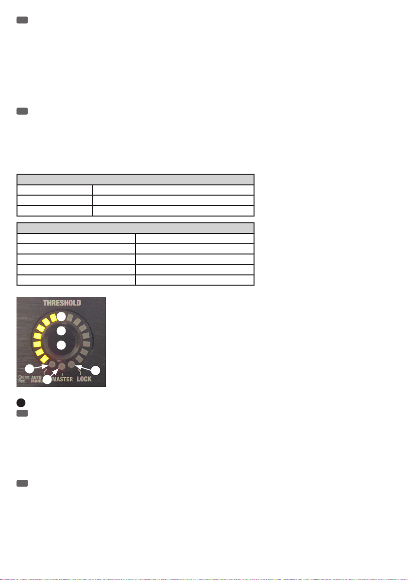
PL
Wskaźnik stanu poziomu wyjść liniowych Master 1 i Master 2. Kiedy dioda stanu świeci się na zielono, z odpowiedniego wyjścia liniowego
Master 1 lub Master 2 zostaje wyprowadzony sygnał wyjściowy (np. dla wejścia liniowego końcówki mocy) o poziomie odpowiadającym sygnałowi
liniowemu. Kiedy dioda stanu jest wyłączona, z odpowiedniego wyjścia liniowego Master 1 lub Master 2 zostaje wyprowadzony sygnał wyjściowy
(np. dla wejścia mikrofonowego stołu mikserskiego) o poziomie obniżonym o 20 dB. Kolejnym krokiem jest wybór wyjścia liniowego, którego poziom
wyjściowy chcemy zmienić. W tym celu należy nacisnąć przycisk pokrętła enkodera przyrostowego MASTER, a następnie za pomocą pokrętła wybrać
żądane wyjście liniowe Master 1 lub Master 2 (dioda stanu pulsuje na czerwono) i potwierdzić wybór naciskając ten sam przycisk. Nacisnąć przycisk
pokrętła enkodera przyrostowego MASTER i przekręcić pokrętło tak mocno, aż dioda stanu sygnału liniowego zacznie pulsować na czerwono. Teraz
należy nacisnąć ponownie przycisk pokrętła enkodera przyrostowego MASTER, co spowoduje przełączenie i zmianę poziomu sygnału wyjściowego z
charakterystycznego dla liniowego na niższy. Jeżeli przycisk nie zostanie naciśnięty w ciągu ok. 10 sekund, żadne zmiany nie nastąpią, a dioda
przestanie pulsować.
IT
Visualizzazione dello stato del livello delle uscite di linea Master1 e Master2. Se il LED di stato si accende in verde, il segnale della
corrispondente uscita di linea Master1 o Master2 ha un livello di linea (ad esempio per l'ingresso di linea di un finale di potenza). Il LED di stato non
è acceso se il segnale della corrispondente uscita di linea Master1 o Master2 ha un livello ridotto di 20dB (ad esempio per l'ingresso di microfono
di un mixer). Selezionare innanzitutto l'uscita di linea di cui si intende modificare il livello di uscita (Master1 o Master2) premendo la manopola
MASTER; il LED di stato lampeggia in rosso. Premere il pulsante per confermare la selezione. Premere la manopola MASTER e ruotarla fino a quando
il LED di stato LINE lampeggia in rosso. Premere ora brevemente la manopola MASTER per passare il livello di uscita da Line a ridotto e viceversa. Se
il tasto non viene premuto entro una decina di secondi, la sensibilità non cambia e il LED smette di lampeggiare.
STATUS LED MASTER 1 & 2
LED flashing red: ready to switch
LED MASTER 1 green Volume setting Master 1
LED MASTER 2 green Volume setting Master 2
STATUS LED LINE
LED flashing red: ready to switch
LED MASTER 1 green & LINE LED green Master 1 Line level
LED MASTER 2 green & LINE LED green Master 2 Line level
LED MASTER 1 green & LINE LED off Master 1 volume attenuation by 20 dB
LED MASTER 2 green & LINE LED off Master 2 volume attenuation by 20 dB
30
29
31
32
33
29
THRESHOLD
EN
When the levels of input channels drop below a certain threshold, these will be muted by this feature. This means that for the transmission of a
channel, background noise, feedback and unwanted comb-filter effects from other active channels are effectively suppressed and the speech
intelligibility is thus enhanced. When the levels of input channels rise above a certain threshold, these will be automatically activated. The rotary
encoder for setting the threshold is disabled during the automatic operation (status LED N° 32 = green). The threshold value is automatically adapted
to the volume of ambient sounds. Rotary encoder for the manual setting of the threshold (-50 dB to +10 dB) for the automatic activation of the input
channels (status LED N° 32 = red). Adjust the threshold so that ambient noise does not automatically activate an input channel, but that the
activation of a channel by a speaker etc...remains possible.
DE
Eingangs-Kanäle, deren Signal-Pegel unter einem bestimmten Schwellenwert liegen, werden mit Hilfe dieser Funktion stumm geschaltet. Somit
werden bei der Übertragung eines Kanals Nebengeräusche, Rückkopplungen und unerwünschte Kammfiltereffekte durch weitere offene Kanäle
wirkungsvoll unterdrückt und die Sprachverständlichkeit gesteigert. Eingangs-Kanäle, deren Signal-Pegel über einem bestimmten Schwellenwert
liegen, werden automatisch aktiviert. Der Drehgeber ist für die Einstellung des Schwellenwerts während des automatischen Betriebs deaktiviert
(Status-LED Nr. 32 = grün). Der Schwellenwert wird automatisch an die Lautstärke der Umgebungsgeräusche angepasst. Drehgeber für die manuelle
Einstellung des Schwellenwerts (-50 dB bis +10 dB) für die automatische Aktivierung der Eingangskanäle (Status-LED Nr. 32 = rot). Stellen Sie den
Schwellenwert so ein, dass Umgebungsgeräusche einen Eingangskanal nicht automatisch aktivieren, aber die Aktivierung eines Kanals durch einen
Sprecher etc. ermöglicht wird.
34
20
Page 21

FR
Cette fonction permet de couper automatiquement (Mute) les canaux d'entrée sur lesquels le niveau du signal descend en dessous d'un certain
seuil. On évite ainsi l'accumulation de bruits ambiants, d'éventuels parasites et l'apparition d'effets de filtre en peigne : autant de phénomènes
inévitables dès que plusieurs micros sont ouverts simultanément, et qui nuisent à l'intelligibilité de la voix. Les canaux d'entrée sur lesquels le niveau
du signal est supérieur à la valeur de seuil sont, quant à eux, automatiquement activés. En mode de fonctionnement automatique, l'encodeur de
réglage de la valeur de seuil est automatiquement désactivé (indicateur LED n°32 = vert). La valeur de seuil s'adapte automatiquement en fonction
du niveau de bruit ambiant. Encodeur pour le réglage manuel de la valeur de seuil (de -50 dB à +10 dB) de fermeture/ouverture automatique des
canaux d'entrée (indicateur LED n°32 = rouge). Réglez la valeur de seuil de façon à ce que le canal d'entrée reste fermé sur le bruit de fond, mais
s'ouvre dès apparition du signal "utile" (parole, etc.).
ES
Esta función silenciará los canales de entrada con un nivel de señal inferior a un determinado umbral. De esta forma se evitará con eficacia el
ruido de fondo de canal, la realimentación acústica y los molestos efectos de filtro de peine que se producen al tener muchos canales abiertos, y se
conseguirá una mayor inteligibilidad de la voz. Los canales de entrada con un nivel de señal superior a dicho umbral se activarán automáticamente.
En modo automático, el control giratorio está desactivado y no sirve para regular el valor umbral (LED de estado32 de color verde). El nivel umbral
se ajusta automáticamente según el volumen del ruido de fondo. En modo manual, el nivel umbral (−50dB a +10dB) se ajusta con el control
giratorio para que los canales de entrada se activen automáticamente (LED de estado32 de color rojo). Ajuste el umbral de modo que el ruido de
fondo no active automáticamente un canal de entrada, sino que se active al hablar un orador, etc.
PL
Dzięki tej funkcji kanały wejściowe o poziomach sygnałów znajdujących się poniżej określonej wartości progowej zostaną włączone bezgłośnie
(bez trzasków). Dzięki temu podczas przekazu na danym kanale dodatkowe odgłosy, sprzężenia zwrotne oraz niechciane efekty działania filtra
grzebieniowego pochodzące z pozostałych otwartych kanałów zostaną skutecznie stłumione, a wyrazistość (stopień zrozumiałości) mowy ulegnie
zwiększeniu. Kanały wejściowe o poziomach sygnałów znajdujących się poniżej określonej wartości progowej zostaną automatycznie aktywowane.
Podczas automatycznej pracy pokrętło enkodera przyrostowego do ustawiania wartości progowej zostaje dezaktywowane (dioda stanu nr 32 świeci
się na zielono). Wartość progowa jest automatycznie dostosowywana do głośności hałasu otoczenia. Pokrętło enkodera przyrostowego do ręcznego
ustawiania wartości progowej (od –50 dB do +10 dB) w celu automatycznej aktywacji kanałów wejściowych (dioda stanu nr 32 świeci się na
czerwono). Poziom wartości progowej należy ustawić tak, aby hałas otoczenia nie włączył automatycznie kanału wejściowego, przy czym włączenie
danego kanału przez użytkownika urządzenia musi być nadal możliwe.
IT
I canali di ingresso con livelli di segnale al di sotto di un determinato valore soglia vengono silenziati con questa funzione. In questo modo,
durante la trasmissione di un canale si evitano i rumori di fondo, i ritorni e gli indesiderati effetti di filtro a pettine che si producono quando ci sono
molti canali aperti; anche l'intelligibilità della voce migliora. I canali di ingresso con livelli di segnale al di sopra di un determinato valore soglia si
attivano automaticamente. In modalità automatica, la manopola per l'impostazione del valore soglia è disattivata (LED di stato n.32= verde). Il
valore soglia viene impostato automaticamente sul volume del rumore di fondo. In modo manuale, il valore soglia (da -50dB a +10dB) si regola con
la manopola per l'attivazione automatica dei canali d'ingresso (LED di stato n.32= rosso). Impostare il valore soglia in modo che un canale
d'ingresso non sia attivato dal rumore di fondo ma ad esempio da un oratore.
30
LED DISPLAY THRESHOLD / LED-ANZEIGE THRESHOLD / COURONNE DE LED THRESHOLD / CORONA DE LED THRESHOLD / WSKAŹNIK
DIODOWY PROGU („THRESHOLD”) / INDICATORE LED THRESHOLD
EN
15-segment LED display for viewing the threshold setting in both automatic and manual operation.
DE
15-Segment LED-Anzeige für die Visualisierung der Einstellung des Schwellenwerts im automatischen und manuellen Betrieb.
FR
Couronne de 15 LED, visualisant la valeur du niveau de seuil en mode automatique et manuel.
ES
Corona LED de 15segmentos para indicar el nivel umbral en los modos automático y manual.
PL
Składający się z 15 diod wskaźnik, który w jasny i widoczny sposób informuje o ustawieniu wartości progowej podczas pracy w trybie
automatycznym i ręcznym.
IT
Indicatore LED da 15 segmenti che indica l'impostazione del valore soglia in modalità automatica e manuale.
31
PUSH-BUTTON THRESHOLD / DRUCKTASTER THRESHOLD / ENCODEUR/TOUCHE THRESHOLD / PULSADOR THRESHOLD / PRZYCISK
PROGU / TASTO THRESHOLD
EN
Push-button to select the automatic or manual setting of the threshold value, the slave mode and the locking of the controls.
DE
Drucktaster zum Auswählen der automatischen bzw. manuellen Einstellung des Schwellenwerts, des Slave-Betriebs und der Sperrung der
Bedienelemente.
FR
Cet encodeur permet de choisir le réglage automatique ou manuel de la valeur de seuil, le mode Slave et le verrouillage des contrôles de
l'AM8.
ES
Pulsador para seleccionar el nivel umbral en los modos automático y manual, el modo esclavo y el bloqueo del control.
PL
Przycisk wyboru automatycznego lub ręcznego ustawienia wartości progowej, trybu urządzenia podporządkowanego i blokowania elementów
obsługi.
IT
Pulsante per la selezione dell'impostazione automatica o manuale del valore soglia, della modalità slave e del blocco dei controlli.
21
Page 22
32
STATUS-LED THRESHOLD AUTO / MANUAL
EN
The status LED indicates the operating mode of the threshold value (green = automatic adjustment of the threshold value, red = manual setting
of the threshold value, see point 29). To change the operating mode, press the push-button of the THRESHOLD rotary encoder (one of the 3 LEDs
AUTO / MANUAL / MASTER or LOCK now flashes red). If necessary, turn the THRESHOLD rotary encoder until the status LED AUTO / MANUAL flashes
red and now press the push-button of the THRESHOLD rotary encoder again. If the push-button is not pressed within 10 seconds, there will be no
change and the LED stops flashing.
DE
Die Status-LED zeigt die Betriebsart der Einstellung des Schwellenwerts an (Grün = automatische Einstellung des Schwellenwerts, Rot =
manuelle Einstellung des Schwellenwerts, siehe auch Punkt 29). Um die Betriebsart zu wechseln, betätigen Sie zuerst den Drucktaster des
Drehgebers THRESHOLD (eine der 3 LEDs AUTO / MANUAL, MASTER oder LOCK blinkt nun rot), drehen gegebenenfalls den Drehgeber THRESHOLD
so weit, bis die Status-LED AUTO / MANUAL rot blinkt und betätigen nun abermals den Drucktaster des Drehgebers THRESHOLD. Wird der
Drucktaster innerhalb von ca. 10 Sekunden nicht betätigt, erfolgt keine Änderung und das Blinken der LED stoppt.
FR
Cet indicateur LED indique le mode de réglage de la valeur de seuil (vert = réglage automatique, rouge = réglage manuel, voir aussi le point
29). Pour changer de mode de réglage de la valeur de seuil, appuyez tout d'abord sur l'encodeur THRESHOLD (une des 3 LED AUTO / MANUAL,
MASTER ou LOCK se met alors à clignote en rouge). Si nécessaire, tournez alors l'encodeur jusqu'à faire clignoter la LED AUTO / MANUAL, puis
appuyez de nouveau dessus. Si vous n'appuyez pas de nouveau sur l'encodeur dans les 10 secondes, aucune modification n'intervient, et la LED
s'arrête de clignoter.
ES
El LED de estado indica el modo de ajuste del nivel umbral (verde= ajuste automático del umbral, rojo= ajuste manual del umbral, ver
punto29). Para cambiar el modo, primero pulse el control giratorio THRESHOLD (uno de los 3LED AUTO/MANUAL, MASTER o LOCK parpadeará de
color rojo), si es necesario gire el control giratorio hasta que el LED de estado AUTO/MANUAL parpadee en rojo, y pulse de nuevo el control giratorio
THRESHOLD. Tenga en cuenta que si no pulsa el control giratorio en 10segundos, no se introducirá ningún cambio y el LED dejará de parpadear.
PL
Dioda stanu informuje o trybie pracy związanym z ustawieniem wartości progowej (kolor zielony = automatyczne ustawianie wartości
progowej, kolor czerwony = ręczne ustawianie wartości progowej; patrz również punkt 29). W celu zmiany trybu pracy najpierw należy nacisnąć
przycisk pokrętła enkodera przyrostowego THRESHOLD (jedna z 3 diod AUTO/MANUAL, MASTER lub LOCK pulsuje teraz na czerwono), przekręcić
pokrętło enkodera przyrostowego THRESHOLD tak mocno, aż dioda stanu automatycznego/ręcznego (tj. dioda AUTO/MANUAL) zacznie pulsować na
czerwono, a następnie nacisnąć ponownie przycisk pokrętła enkodera przyrostowego THRESHOLD. Jeżeli przycisk nie zostanie naciśnięty w ciągu
ok. 10 sekund, żadne zmiany nie nastąpią, a dioda przestanie pulsować.
IT
Il LED di stato indicava la modalità di funzionamento dell'impostazione del valore soglia (verde= impostazione automatica del valore soglia,
rosso= impostazione manuale del valore soglia, v.anche il punto29). Per cambiare la modalità di funzionamento, premere innanzitutto la manopola
THRESHOLD (uno dei 3 LED AUTO / MANUAL, MASTER o LOCK ora lampeggia in rosso), eventualmente ruotare la manopola THRESHOLD fino a
quando il LED di stato AUTO / MANUAL lampeggia in rosso e premere brevemente la manopola THRESHOLD. Se il tasto non viene premuto entro una
decina di secondi, la sensibilità non cambia e il LED smette di lampeggiare.
STATUS LED THRESHOLD AUTO / MANUAL
LED flashing red: ready to switch
LED AUTO / MANUAL green automatic setting of the threshold value
LED AUTO / MANUAL red manual adjustment of the threshold value
33
STATUS-LED MASTER
EN
When using a single AM8 automatic mixer, it must be configured as a master unit. When daisy-chaining up to 16 AM8 automatic mixers using
the LINK IN / LINK OUT interface on the rear panel of the device (see point 14), the device that must serve as the master unit needs to be configured
as the master unit. If the status LED MASTER is permanently green, then the AM8 automatic mixer is configured as the master device, and if the LED
is not lit, as a slave device. When daisy-chaining, the audio inputs of all slave units of the AM8 automatic mixer in the system will be routed to the
line outputs Master 1 and Master 2 of the master unit (see DAISY-CHAIN) To change the operating mode, press the push-button of the THRESHOLD
rotary encoder (one of the 3 LEDs AUTO / MANUAL / MASTER or LOCK now flashes red). If necessary, turn the THRESHOLD rotary encoder until the
status LED MASTER flashes red and now press the push-button of the THRESHOLD rotary encoder again. If the push-button is not pressed within 10
seconds, there will be no change and the LED stops flashing.
DE
Beim Einsatz eines einzelnen AM8 Automatik-Mixers, muss dieser als Master-Einheit konfiguriert sein. Beim Kaskadieren von bis zu 16 AM8
Automatik-Mixern mit Hilfe der LINK IN / LINK OUT Schnittstelle auf der Rückseite des Geräts (siehe Punkt 14), muss das Gerät, welches als
Master-Einheit dienen soll, als Master-Einheit konfiguriert sein. Leuchtet die Status-LED MASTER permanent grün, ist der AM8 Automatik-Mixer als
Master-Gerät konfiguriert, leuchtet die LED nicht, als Slave-Gerät. Die Audio-Eingänge aller Slave-Einheiten des AM8 Automatik-Mixers im System,
werden beim Kaskadieren auf die Line-Ausgänge Master 1 und Master 2 der Master-Einheit geroutet (siehe KASKADIERUNG). Um die Betriebsart zu
wechseln, betätigen Sie zunächst den Drucktaster des Drehgebers THRESHOLD (eine der 3 LEDs AUTO / MANUAL, MASTER oder LOCK blinkt nun
rot), drehen gegebenenfalls den Drehgeber THRESHOLD so weit, bis die Status-LED MASTER rot blinkt und betätigen nun abermals den Drucktaster
des Drehgebers THRESHOLD. Wird der Drucktaster innerhalb von ca. 10 Sekunden nicht betätigt, erfolgt keine Änderung und das Blinken der LED
stoppt.
FR
Si vous n'utilisez qu'un seul mixeur automatique AM8, il doit être configuré en mode Master. Si vous cascadez plusieurs mixeurs automatiques AM8
(16 au maximum) via les connecteurs LINK IN / LINK OUT à l'arrière de l'appareil (point 14), l'AM8 que vous désirez utiliser comme maître doit être
configuré en mode Master. Si l'indicateur LED MASTER est allumé en vert, c'est que l'AM8 est configuré en mode Master ; s'il est éteint, l'AM8 est
configuré en mode Slave. Les signaux audio arrivant sur les entrées de tous les AM8 esclaves du système sont sommés et sortent sur les sorties Master 1
et Master 2 de l'AM8 maître (voir CASCADE). Pour changer de mode, appuyez tout d'abord sur l'encodeur THRESHOLD (une des 3 LED AUTO / MANUAL,
MASTER ou LOCK se met alors à clignote en rouge). Si nécessaire, tournez alors l'encodeur jusqu'à faire clignoter la LED MASTER, puis appuyez de
nouveau dessus. Si vous n'appuyez pas de nouveau sur l'encodeur dans les 10 secondes, aucune modification n'intervient, et la LED s'arrête de clignoter.
22
Page 23

ES
Cuando se utiliza un único mezclador automático AM8, debe configurarse como equipo maestro. Al conectar en cascada hasta 16mezcladores
automáticos AM8 mediante el puerto LINK IN / LINK OUT del panel posterior (ver punto14), debe configurar como master el equipo que va a
funcionar como maestro. Si el LED de estado MASTER se ilumina de color verde, el mezclador automático AM8 está configurado como un equipo
maestro; si está apagado, es un equipo esclavo. Las entradas de audio de todos los mezcladores automáticos esclavos AM8 de un sistema en
cascada tienen las salidas de línea Master1 y Master2 del mezclador maestro (ver CONEXIÓN EN CASCADA). Para cambiar el modo, primero pulse
el control giratorio THRESHOLD (uno de los 3LED AUTO/MANUAL, MASTER o LOCK parpadeará de color rojo), si es necesario gire el control giratorio
hasta que el LED de estado MASTER parpadee en rojo, y pulse de nuevo el control giratorio THRESHOLD. Tenga en cuenta que si no pulsa el control
giratorio en 10segundos, no se introducirá ningún cambio y el LED dejará de parpadear.
PL
W przypadku korzystania z jednego automatycznego miksera AM8 musi on zostać skonfigurowany jako jednostka (urządzenie) główna. W
przypadku kaskadowania maksymalnie 16 automatycznych mikserów AM8 za pomocą interfejsu LINK IN/LINK OUT znajdującego się na tylnym
panelu urządzenia (patrz punkt 14) urządzenie mające pełnić funkcję urządzenia głównego musi zostać skonfigurowane jako jednostka główna.
Jeżeli dioda stanu MASTER świeci ciągłym zielonym światłem, oznacza to, że automatyczny mikser AM8 jest skonfigurowany jako urządzenie
główne, a gdy dioda nie świeci w ogóle, jako urządzenie podporządkowane. W przypadku kaskadowania wejścia audio wszystkich jednostek
automatycznego miksera AM8 pracujących w systemie w trybie urządzeń podporządkowanych będą przetrasowywane na wyjścia liniowe Master 1 i
Master 2 jednostki głównej (patrz KASKADOWANIE). W celu zmiany trybu pracy najpierw należy nacisnąć przycisk pokrętła enkodera przyrostowego
THRESHOLD (jedna z 3 diod AUTO/MANUAL, MASTER lub LOCK pulsuje teraz na czerwono), przekręcić pokrętło enkodera przyrostowego THRESHOLD
tak mocno, aż dioda stanu MASTER zacznie pulsować na czerwono, a następnie nacisnąć ponownie przycisk pokrętła enkodera przyrostowego
THRESHOLD. Jeżeli przycisk nie zostanie naciśnięty w ciągu ok. 10 sekund, żadne zmiany nie nastąpią, a dioda przestanie pulsować.
IT
Se si utilizza un solo mixer automatico AM8, deve essere configurato come unità master. Se si collegano a cascata fino a 16mixer automatici
AM8 tramite la porta LINK IN / LINK OUT che si trova sul lato posteriore dell'apparecchio (v.punto14), l'apparecchio che deve fungere da master
deve essere configurato come master. Se il LED di stato MASTER rimane acceso in verde, il mixer automatico AM8 è configurato come mixer master,
mentre se il LED non è acceso, l'apparecchio è in modalità slave. Gli ingressi audio di tutte le unità slave del mixer automatico AM8 di un sistema in
cascata sono instradati nelle uscite di linea Master1 e Master2 dell'unità master (v.COLLEGAMENTO A CASCATA). Per cambiare la modalità di
funzionamento, premere innanzitutto la manopola THRESHOLD (uno dei 3LED AUTO / MANUAL, MASTER o LOCK ora lampeggia in rosso),
eventualmente ruotare la manopola THRESHOLD fino a quando il LED di stato MASTER lampeggia in rosso e premere brevemente la manopola
THRESHOLD. Se il tasto non viene premuto entro una decina di secondi, la sensibilità non cambia e il LED smette di lampeggiare.
STATUS LED MASTER
LED flashing red: ready to switch
LED MASTER green The device is a master unit
LED MASTER off The device is a slave unit
34
STATUS-LED LOCK
EN
In order to protect the device against accidental operation, the controls can be locked out of operation. If the status LED LOCK lights up green
permanently, the controls are not locked. If the LED is permanently red, the controls are locked. To change the operating mode, press the
push-button of the THRESHOLD rotary encoder (one of the 3 LEDs AUTO / MANUAL / MASTER or LOCK now flashes red). If necessary, turn the
THRESHOLD rotary encoder until the status LED LOCK flashes red and now press the push-button of the THRESHOLD rotary encoder again. If the
push-button is not pressed within 10 seconds, there will be no change and the LED stops flashing.
DE
Um das Gerät vor unbeabsichtigter Bedienung zu schützen, können die Bedienelemente gesperrt und damit außer Funktion gesetzt werden.
Leuchtet die Status-LED LOCK permanent grün, sind die Bedienelemente nicht gesperrt, leucht die LED permanent rot, sind die Bedienelemente
gesperrt. Um den Betriebszustand zu wechseln, betätigen Sie zunächst den Drucktaster des Drehgebers THRESHOLD (eine der 3 LEDs AUTO /
MANUAL, MASTER oder LOCK blinkt nun rot), drehen gegebenenfalls den Drehgeber THRESHOLD so weit, bis die Status-LED LOCK rot blinkt und
betätigen nun abermals den Drucktaster des Drehgebers THRESHOLD. Wird der Drucktaster innerhalb von ca. 10 Sekunden nicht betätigt, erfolgt
keine Änderung und das Blinken der LED stoppt.
FR
Pour protéger l'appareil contre toute utilisation incontrôlée, une fonction permet de verrouiller ses contrôles, et de le contrôler à distance.
Lorsque l'indicateur LED LOCK est allumé en vert, les contrôles de l'AM8 ne sont pas verrouillés ; s'il est allumé en rouge, les contrôles sont
verrouillés. Pour modifier le statut de verrouillage de l'appareil, appuyez tout d'abord sur l'encodeur THRESHOLD (une des 3 LED AUTO / MANUAL,
MASTER ou LOCK se met alors à clignote en rouge). Si nécessaire, tournez alors l'encodeur jusqu'à faire clignoter la LED LOCK, puis appuyez de
nouveau dessus. Si vous n'appuyez pas de nouveau sur l'encodeur dans les 10 secondes, aucune modification n'intervient, et la LED s'arrête de
clignoter.
ES
Para evitar operar el equipo de forma involuntaria, es posible bloquear y desactivar los controles. Si se ilumina el LED de estado LOCK de color
verde, los controles están desbloqueados; si el LED se ilumina de color rojo, los controles están bloqueados. Para cambiar el modo, primero pulse el
control giratorio THRESHOLD (uno de los 3LED AUTO/MANUAL, MASTER o LOCK parpadeará de color rojo), si es necesario gire el control giratorio
hasta que el LED de estado LOCK parpadee en rojo, y pulse de nuevo THRESHOLD. Tenga en cuenta que si no pulsa el control giratorio en
10segundos, no se introducirá ningún cambio y el LED dejará de parpadear.
23
Page 24

PL
Aby uniemożliwić przypadkowe aktywowanie funkcji urządzenia, można zablokować elementy obsługi, wyłączając ich działanie. Jeżeli dioda
stanu LOCK świeci ciągłym zielonym światłem, oznacza to, że elementy obsługi nie są zablokowane. Elementy obsługi są zablokowane, gdy dioda
świeci ciągłym czerwonym światłem. W celu zmiany stanu blokady najpierw należy nacisnąć przycisk pokrętła enkodera przyrostowego THRESHOLD
(jedna z 3 diod AUTO/MANUAL, MASTER lub LOCK pulsuje teraz na czerwono), przekręcić pokrętło enkodera przyrostowego THRESHOLD tak mocno,
aż dioda stanu LOCK zacznie pulsować na czerwono, a następnie nacisnąć ponownie przycisk pokrętła enkodera przyrostowego THRESHOLD. Jeżeli
przycisk nie zostanie naciśnięty w ciągu ok. 10 sekund, żadne zmiany nie nastąpią, a dioda przestanie pulsować.
IT
Per proteggere l'apparecchio da uso incidentale, è possibile bloccare e pertanto disattivare i controlli. Se il LED di stato LOCK resta acceso in
verde, i controlli non sono bloccati, se invece rimane acceso in rosso, i controlli sono bloccati. Per cambiare lo stato, premere innanzitutto la
manopola THRESHOLD (uno dei 3LED AUTO / MANUAL, MASTER o LOCK ora lampeggia in rosso), eventualmente ruotare la manopola THRESHOLD
fino a quando il LED di stato LOCK lampeggia in rosso e premere brevemente la manopola THRESHOLD. Se il tasto non viene premuto entro una
decina di secondi, la sensibilità non cambia e il LED smette di lampeggiare.
STATUS LED LOCK
LED flashing red: ready to switch
LED LOCK green Controls are not locked
LED LOCK red Controls are locked
STARTUP / INBETRIEBNAHME / MISE EN SERVICE / PUESTA EN MARCHA / URUCHOMIENIE /
MESSA IN FUNZIONE
EN
First use
- Use only balanced cables for the connections of the AM8 automatic mixer.
- To avoid damage to the audio system caused by feedback etc., set the volume of the audio system to minimum during the change of settings and
gently increase the volume.
- Since the AM8 automatic mixer is a 19" device with one height unit, the features, settings and displays that are available or visible directly on the
device are limited. Therefore, it is advisable to adjust all settings via the free AUTOMIX8 PC software. Also, visual checking of the input and output
channels and their settings is very comfortable and clearly arranged in the AUTOMIX8 software.
- In the standard setting of the AM8 automatic mixer, all audio inputs are set to microphone sensitivity, also, the 48 V phantom power is enabled (individual activation / deactivation of the phantom power via the PC software is possible). Do not switch on the equipment until all microphones are connected.
- Using the same type of microphone for all speakers makes it easier to adjust the settings and improves clarity. If different types of microphones are
used, be sure to adjust the input gain and equalizer settings accordingly.
- Make sure that all connected microphones are set to the same level, so as to ensure proper operation of the AM8 automatic mixer.
DE
Inbetriebnahme
- Verwenden Sie für die Verkabelung des AM8 Automatik-Mixers ausschließlich symmetrische Kabel.
- Um Schäden am Audio-System durch Rückkopplungen etc. zu vermeiden, stellen Sie während der Änderung von Einstellungen die Lautstärke des
Audio-Systems auf ein Minimum und erhöhen nur vorsichtig die Lautstärke.
- Da es sich bei dem AM8 Automatik-Mixer um ein 19" Gerät mit einer Höheneinheit handelt, sind die Funktionen, Einstellungsmöglichkeiten und
Anzeigen, die direkt auf dem Gerät abrufbar bzw. sichtbar sind, begrenzt. Daher empfiehlt es sich, alle Einstellungen über die kostenfreie PC-Software
AUTOMIX8 vorzunehmen. Auch ist die visuelle Kontrolle der Eingangs- und Ausgangs-Kanäle und deren Einstellungen mit Hilfe der AUTOMIX8 Software
sehr komfortabel und übersichtlich.
- In der Standard-Einstellung des AM8 Automatik-Mixers sind alle Audio-Eingänge auf Mikrofon-Empfindlichkeit eingestellt, auch die 48V Phantomspeisung ist aktiviert (individuelle Aktivierung / Deaktivierung der Phantomspeisung durch die PC-Software möglich). Schalten Sie deshalb das Gerät
erst ein, nachdem alle Mikrofone angeschlossen wurden.
- Die Verwendung des gleichen Mikrofontyps für alle Sprecher erleichtert die Einstellungen und verbessert die Übersichtlichkeit. Wenn unterschiedliche
Mikrofontypen verwendet werden, achten Sie darauf, Eingangsvorverstärkung und Equalizer-Einstellungen entsprechend anzupassen.
- Achten Sie darauf, dass alle angeschlossenen Mikrofone auf den gleichen Pegel eingestellt sind, damit eine einwandfreie Funktion des AM8 Automatik-Mixers gewährleistet ist.
FR
Utilisation
- Pour le câblage du mixeur automatique AM8, utilisez exclusivement des câbles symétriques.
- Pour éviter d'éviter le système audio suite à un Larsen, etc., réglez au minimum le volume sonore du système audio lorsque vous procédez à une
modification de ses réglages, et montez ensuite progressivement le volume.
- Comme le mixeur automatique AM8 est un appareil rackable 1 U, l'espace disponible est limité : du coup, les réglages et visualisations disponibles
directement sur l'appareil sont limités. Tous les réglages sont en revanche disponibles par l'intermédiaire de l'application pour PC gratuite AUTOMIX8.
Le logiciel AUTOMIX8 facilite le contrôle visuel de l'activité sur les canaux d'entrée et de sortie, ainsi que leur paramétrage.
- Dans le réglage standard du mixeur automatique de l'AM8, toutes les entrées audio fonctionnent en sensibilité Micro, et la tension d'alimentation
fantôme 48 V est activée. Le logiciel AUTOMIX8 autorise l'activation/désactivation par canal de l'alimentation fantôme. Ne mettez l'appareil sous
tension que lorsqu'il est parvenu à la température de la pièce.
- Il est recommandé d'utiliser des microphones de type identique sur chaque personne, ce qui facilite les réglages et améliore la clarté sonore. Si vous
utilisez des microphones de types différents, attention à adapter le gain de préampli micro et les réglages d'égalisation.
- Veillez à ce que tous les microphones connectés soient réglés à un niveau identique, afin de garantir un fonctionnement impeccable du mixeur
automatique AM8.
24
Page 25

ES
Puesta en marcha
- Para el cableado del mezclador automático AM8, emplee solo cables balanceados.
- Para no dañar el sistema debido a realimentaciones acústicas, etc., sitúe al mínimo el volumen del sistema de audio antes de conectar o desconectar
nada, y súbalo después con sumo cuidado.
- Como el mezclador automático AM8 es un equipo de 19" de una unidad de altura de rack, la accesibilidad a las funciones, ajustes e indicadores es
limitada. Por ello, se recomienda realizar los ajustes mediante el software gratuito AUTOMIX8. Además, con el software AUTOMIX8, el control visual de
los canales de entrada y de salida, incluidos los ajustes, es muy rápido e intuitivo.
- En la configuración por defecto del mezclador automático AM8, todas las entradas de audio tienen la sensibilidad de micrófono, y la alimentación
fantasma de 48V está activada (es posible activar/desactivar por software la alimentación fantasma de cada canal). Por tanto, encienda el equipo solo
después de haber conectado todos los micrófonos.
- Si todos los oradores usan el mismo tipo de micrófono, la configuración será mucho más fácil y clara. Si se emplean varios tipos de micrófonos, no
olvide ajustar la ganancia de entrada y la ecualización.
- Asegúrese de que todos los micrófonos conectados dan el mismo nivel; de esta manera, el mezclador automático AM8 funcionará sin problemas.
PL
Uruchomienie
– Do okablowania automatycznego miksera AM8 należy użyć wyłącznie symetrycznych kabli.
– Aby nie uszkodzić systemu audio wskutek sprzężenia zwrotnego, podczas dostosowywania ustawień należy ustawić głośność systemu audio na
wartość minimalną i ostrożnie ją zwiększać.
– W związku z tym, że szerokość automatycznego miksera AM8 wynosi 19 cali, liczba funkcji i ustawień, które można bezpośrednio przywołać oraz
wskaźników znajdujących się bezpośrednio na urządzeniu jest ograniczona. Dlatego też w celu zmiany ustawień zaleca się skorzystanie z darmowego
oprogramowania komputerowego AUTOMIX8. Ponadto przejrzysty interfejs oprogramowania AUTOMIX8 umożliwia sterowanie za pomocą interfejsu
graficznego kanałami wejściowymi i wyjściowymi oraz zmianę ich ustawień w komfortowy sposób.
– Automatyczny mikser AM8 został domyślnie ustawiony na czułość odpowiednią dla sygnału mikrofonowego na wszystkich wejściach audio. Ponadto
48 V zasilanie phantom jest włączone (oprogramowanie komputerowe umożliwia włączenie/wyłączenie zasilania phantom). Włączyć urządzenie dopiero wtedy, gdy podpięte zostaną wszystkie mikrofony.
– Zastosowanie mikrofonów tego samego typu dla wszystkich użytkowników urządzenia ułatwia konfigurację ustawień i poprawia przejrzystość. W
przypadku użycia mikrofonów różnych typów należy pamiętać o odpowiednim dostosowaniu wstępnego wzmocnienia wejścia i ustawień korektora
dźwięku.
– Aby zagwarantować prawidłowe działanie automatycznego miksera AM8, należy pamiętać o wyregulowaniu wszystkich podpiętych mikrofonów do
identycznego poziomu.
IT
Messa in funzione
- Per il cablaggio del mixer automatico AM8 utilizzare unicamente cavi bilanciati.
- Per evitare che il sistema audio venga danneggiato da ritorni ecc., mentre si modificano le impostazioni regolare il volume del sistema audio al minimo
e alzarlo quindi con attenzione.
- Poiché il mixer automatico AM8 è un apparecchio da 19" con un'unità per montaggio in rack, le funzioni, opzioni di impostazione e gli indicatori
direttamente accessibili e visibili sull'apparecchio sono limitati. Si consiglia pertanto di effettuare tutte le impostazioni tramite il software gratuito per
PC AUTOMIX8. Con l'AUTOMIX8 risulta facile e intuitivo eseguire anche il controllo visuale e le impostazioni dei canali di ingresso e di uscita.
- Nelle impostazioni standard del mixer automatico AM8 tutti gli ingressi audio hanno impostato la stessa sensibilità del microfono e l'alimentazione
phantom 48V è attivata (possibilità di attivazione/disattivazione individuale dell'alimentazione phantom tramite il software del computer). Accendere
quindi l'apparecchio solo dopo che tutti i microfoni sono stati collegati.
- Se si utilizza lo stesso tipo di microfono per tutti gli oratori, eseguire le impostazioni sarà molto più facile e intuitivo. Se si utilizzano microfoni di
diverso tipo, ricordare di adattare la preamplificazione d'ingresso e le impostazioni dell'equalizzatore.
- Ricordare che per garantire il corretto funzionamento del mixer automatico AM8 tutti i microfoni collegati devono essere impostati sullo stesso livello.
25
Page 26

MASTER
LD SYSTEMS
Adam Hall Germany
61267 Neu-Anspach
LD SYSTEMS
Adam Hall Germany
61267 Neu-Anspach
LD SYSTEMS
Adam Hall Germany
61267 Neu-Anspach
LD SYSTEMS
Adam Hall Germany
61267 Neu-Anspach
110-240 AC / 50-60Hz
MAX 60 W / AC~
RS-232
RESET
+ I - I G
NETWORK AES/EBU OUTPUT
EXTERNAL CONTROL
+ I - I G + I - I G + I - I G + I - I G + I - I G + I - I G + I - I G + I - I G + I - I G + I - I G
LINK IN LINK OUT MASTER
OUTPUT 2
CAUTION! DO NOT OPEN RISK OF ELECTRICAL SHOCK !
AVIS! NE PAS OUVRIR RISQUE DE CHOC ELECTRIQUE !
ACHTUNG! NICHT ÖFFNEN, STROMSCHLAGGEFAHR !
MASTER
OUTPUT 1
CH 8 CH 7 CH 6 CH 5 CH 4 CH 3 CH 2 CH 1
is a registered Brand of
®
SLAVE 1
110-240 AC / 50-60Hz
MAX 60 W / AC~
RS-232
RESET
+ I - I G
NETWORK AES/EBU OUTPUT
EXTERNAL CONTROL
+ I - I G + I - I G + I - I G + I - I G + I - I G + I - I G + I - I G + I - I G + I - I G + I - I G
LINK IN LINK OUT MASTER
OUTPUT 2
CAUTION! DO NOT OPEN RISK OF ELECTRICAL SHOCK !
AVIS! NE PAS OUVRIR RISQUE DE CHOC ELECTRIQUE !
ACHTUNG! NICHT ÖFFNEN, STROMSCHLAGGEFAHR !
MASTER
OUTPUT 1
CH 8 CH 7 CH 6 CH 5 CH 4 CH 3 CH 2 CH 1
is a registered Brand of
®
SLAVE 2
110-240 AC / 50-60Hz
MAX 60 W / AC~
RS-232
RESET
+ I - I G
NETWORK AES/EBU OUTPUT
EXTERNAL CONTROL
+ I - I G + I - I G + I - I G + I - I G + I - I G + I - I G + I - I G + I - I G + I - I G + I - I G
LINK IN LINK OUT MASTER
OUTPUT 2
CAUTION! DO NOT OPEN RISK OF ELECTRICAL SHOCK !
AVIS! NE PAS OUVRIR RISQUE DE CHOC ELECTRIQUE !
ACHTUNG! NICHT ÖFFNEN, STROMSCHLAGGEFAHR !
MASTER
OUTPUT 1
CH 8 CH 7 CH 6 CH 5 CH 4 CH 3 CH 2 CH 1
is a registered Brand of
®
SLAVE 15
110-240 AC / 50-60Hz
MAX 60 W / AC~
RS-232
RESET
+ I - I G
NETWORK AES/EBU OUTPUT
EXTERNAL CONTROL
+ I - I G + I - I G + I - I G + I - I G + I - I G + I - I G + I - I G + I - I G + I - I G + I - I G
LINK IN LINK OUT MASTER
OUTPUT 2
CAUTION! DO NOT OPEN RISK OF ELECTRICAL SHOCK !
AVIS! NE PAS OUVRIR RISQUE DE CHOC ELECTRIQUE !
ACHTUNG! NICHT ÖFFNEN, STROMSCHLAGGEFAHR !
MASTER
OUTPUT 1
CH 8 CH 7 CH 6 CH 5 CH 4 CH 3 CH 2 CH 1
is a registered Brand of
®
DAISY-CHAINING / KASKADIERUNG / CASCADE / CONEXIÓN EN CASCADA / KASKADOWANIE /
COLLEGAMENTO A CASCATA
EN
Daisy-Chaining
Up to 16 LD Systems AM8 automatic mixers can be daisy-chained to an audio system. When daisy-chaining the AM8 automatic mixers using the LINK
IN / LINK OUT interface on the rear panel of the unit, the device that must serve as the master unit needs to be configured as the master unit. All other
AM8 automatic mixers in the audio system will be configured as slave units (see point 33, CONNECTIONS, CONTROL AND DISPLAY ELEMENTS). Connect
the slave units to the master units unit using the supplied connection cable (slave unit LINK OUT -> Master unit LINK IN, see figure). The audio inputs
of all slave units of the AM8 automatic mixer in the system will be routed to the line outputs Master 1 and Master 2 of the master unit.
· Daimlerstr. 9
· Daimlerstr. 9
· Daimlerstr. 9
· Daimlerstr. 9
DE
Kaskadierung
Bis zu 16 der LD Systems AM8 Automatik-Mixer können zu einem Audio-System kaskadiert werden. Beim Kaskadieren der AM8 Automatik-Mixer mit
Hilfe der LINK IN / LINK OUT Schnittstelle auf der Rückseite des Geräts, muss der AM8 Automatik-Mixer, welcher als Master-Einheit eingesetzt werden
soll, als Master-Einheit konfiguriert werden. Alle weiteren AM8 Automatik-Mixer des Audio-Systems werden als Slave-Einheit konfiguriert (siehe Punkt
33, ANSCHLÜSSE, BEDIEN- UND ANZEIGEELEMENTE). Verbinden Sie die Slave-Einheit(en) mit der Master-Einheit mit Hilfe des mitgelieferten Verbindungskabels (Slave-Einheit LINK OUT -> Master-Einheit LINK IN, siehe Abbildung). Die Audio-Eingänge aller Slave-Einheiten des AM8 Automatik-Mixers
im System werden hierbei auf die Line-Ausgänge Master 1 und Master 2 der Master-Einheit geroutet.
FR
Branchement en cascade
Vous pouvez relier en cascade jusqu'à 16 mixeurs automatiques LD Systems AM8 dans un système audio. Dans ce cas de figure, il faut interconnecter
les appareils via leurs connecteurs LINK IN / LINK OUT, situés sur le panneau arrière, et régler en mode Master l'AM8 considéré comme le Maître du
système. Tous les autres AM8 doivent alors être réglés en mode Slave (voir Point 33, CONNECTEURS, RÉGLAGES ET INDICATEURS Reliez ensuite le(s)
appareil(s) esclave(s) à l'AM8 maître à l'aide d'un câble de liaison (LINK OUT du Slave vers LINK IN du Master, voir schéma). Les signaux audio arrivant
sur les entrées de tous les AM8 esclaves du système sont alors sommés sur les bus Master 1 et 2 de l'appareil Master.
ES
Conexión en cascada
A un sistema de audio se pueden conectar en cascada hasta 16mezcladores automáticos AM8 de LD Systems. Al conectar en cascada los mezcladores
automáticos AM8 mediante el puerto LINK IN / LINK OUT del panel posterior, debe configurar como master el AM8 que va a funcionar como maestro.
Hay que configurar el resto de mezcladores automáticos AM8 como esclavos (ver punto33 de la sección CONEXIONES, CONTROLES E INDICADORES).
Conecte los equipos esclavos al maestro mediante los cables suministrados, del LINK OUT del esclavo al LINK IN del maestro (ver figura). Las entradas
de audio de todos los mezcladores esclavos AM8 del sistema tienen las salidas de línea Master1 y Master2 del mezclador maestro.
26
Page 27

PL
Kaskadowanie
Istnieje możliwość kaskadowania maksymalnie 16 automatycznych mikserów AM8 firmy LD Systems do jednego systemu audio. W przypadku kaskadowania automatycznego miksera AM8 za pomocą interfejsu LINK IN/LINK OUT znajdującego się na tylnym panelu urządzenia automatyczny mikser
AM8 mający pełnić funkcję urządzenia głównego musi zostać skonfigurowany jako jednostka główna. Wszystkie pozostałe automatyczne miksery AM8
systemu audio zostaną skonfigurowane jako jednostki podporządkowane (patrz punkt 33, PRZYŁĄCZA, ELEMENTY OBSŁUGI I WSKAŹNIKI). Jednostkę/
Jednostki podporządkowane połączyć z jednostką główną za pomocą dostarczonego w zestawie kabla (jednostka podporządkowana LINK OUT ->
jednostka główna LINK IN, patrz rysunek). Dzięki temu wejścia audio wszystkich jednostek automatycznego miksera AM8 pracujących w systemie w
trybie urządzeń podporządkowanych będą przetrasowywane na wyjścia liniowe Master 1 i Master 2 jednostki głównej.
IT
Collegamento a cascata
A un sistema audio si possono collegare a cascata fino a 16mixer automatici AM8 di LD Systems. Se si collegano a cascata i mixer automatici AM8
tramite la porta LINK IN / LINK OUT che si trova sul lato posteriore dell'apparecchio, l'AM8 che dovrà essere utilizzato come master deve essere
configurato come unità master. Tutti gli altri mixer automatici AM8 del sistema audio vanno configurati come unità slave (v.punto33, CONNESSIONI,
COMANDI E INDICATORI). Collegare le unità slave con l'unità master utilizzando l'apposito cavo fornito in dotazione (unità slave LINK OUT -> unità master LINK IN, v. immagine). Gli ingressi audio di tutte le unità slave del mixer automatico AM8 del sistema sono instradati nelle uscite di linea Master1
e Master2 dell'unità master.
ESTABLISHING A CONNECTION WITH A WINDOWS PC / VERBINDUNG MIT EINEM WINDOWS
PC HERSTELLEN / CONFIGURATION DE LA LIAISON AVEC UN PC SOUS WINDOWS / CONEXIÓN
A UN PC CON WINDOWS / NAWIĄZYWANIE POŁĄCZENIA Z KOMPUTEREM Z SYSTEMEM
OPERACYJNYM WINDOWS / COLLEGAMENTO A UN PC CON SISTEMA OPERATIVO WINDOWS
EN
Install the AUTOMIX8 software on a Windows PC (Windows Vista, WIN 7, WIN 8, screen resolution min. 1366 X 768) and connect the AM8 automatic mixer to the Ethernet interface of the computer using a LAN cable (CAT-5). Since the IP address of the AM8 automatic mixer is factory set to
192.168.1.88, the interface of the computer must be assigned a different IP address (see figure "Properties of Internet Protocol Version 4"). Start the
AUTOMIX8 software, then click with the left mouse button on "MENU", now move the mouse pointer to "CONNECT" and confirm by clicking with the
left mouse button. Click the blue "SEARCH" field in the opening window.
DE
Installieren Sie die AUTOMIX8 Software auf einem Windows-PC (Windows Vista, WIN 7, WIN 8, Bildschirmauflösung min. 1366 x 768) und schließen Sie den AM8 Automatik-Mixer mit Hilfe eines LAN-Kabels (CAT-5) an der Ethernet-Schnittstelle des Rechners an. Da die IP-Adresse des AM8 Automatik-Mixers ab Werk auf 192.168.1.88 gesetzt ist, muss der verwendeten Schnittstelle des Rechners eine andere IP-Adresse zugewiesen werden
(siehe Abbildung "Eigenschaften von Internetprotokoll Version 4"). Starten Sie die AUTOMIX8 Software, klicken mit der linken Maustaste auf "MENU",
bewegen nun den Mauszeiger auf "CONNECT" (verbinden) und bestätigen durch Klicken mit der linken Maustaste. Klicken Sie auf das blaue Feld
"SEARCH" (suchen) im nun geöffneten Fenster.
FR
Installez le logiciel AUTOMIX8 sur votre PC (OS compatibles : Windows Vista, 7 et 8 ; résolution minimale d'écran 1366 x 768) et relier votre mixeur
automatique AM8 au port Ethernet de l'ordinateur, via un câble réseau (CAT-5). Comme l'adresse IP de l'AM8 est réglée automatiquement, en usine,
sur la valeur 192.168.1.88, le port utilisé sur l'ordinateur doit posséder une adresse IP différente (voir la fenêtre de Windows "Propriétés d'Internet
Protocol Versions 4"). Lancez le logiciel AUTOMIX8, cliquez sur "MENU", puis sur "CONNECT". Cliquez ensuite sur le champ bleu "SEARCH" (chercher)
dans la fenêtre qui s'est ouverte.
27
Page 28
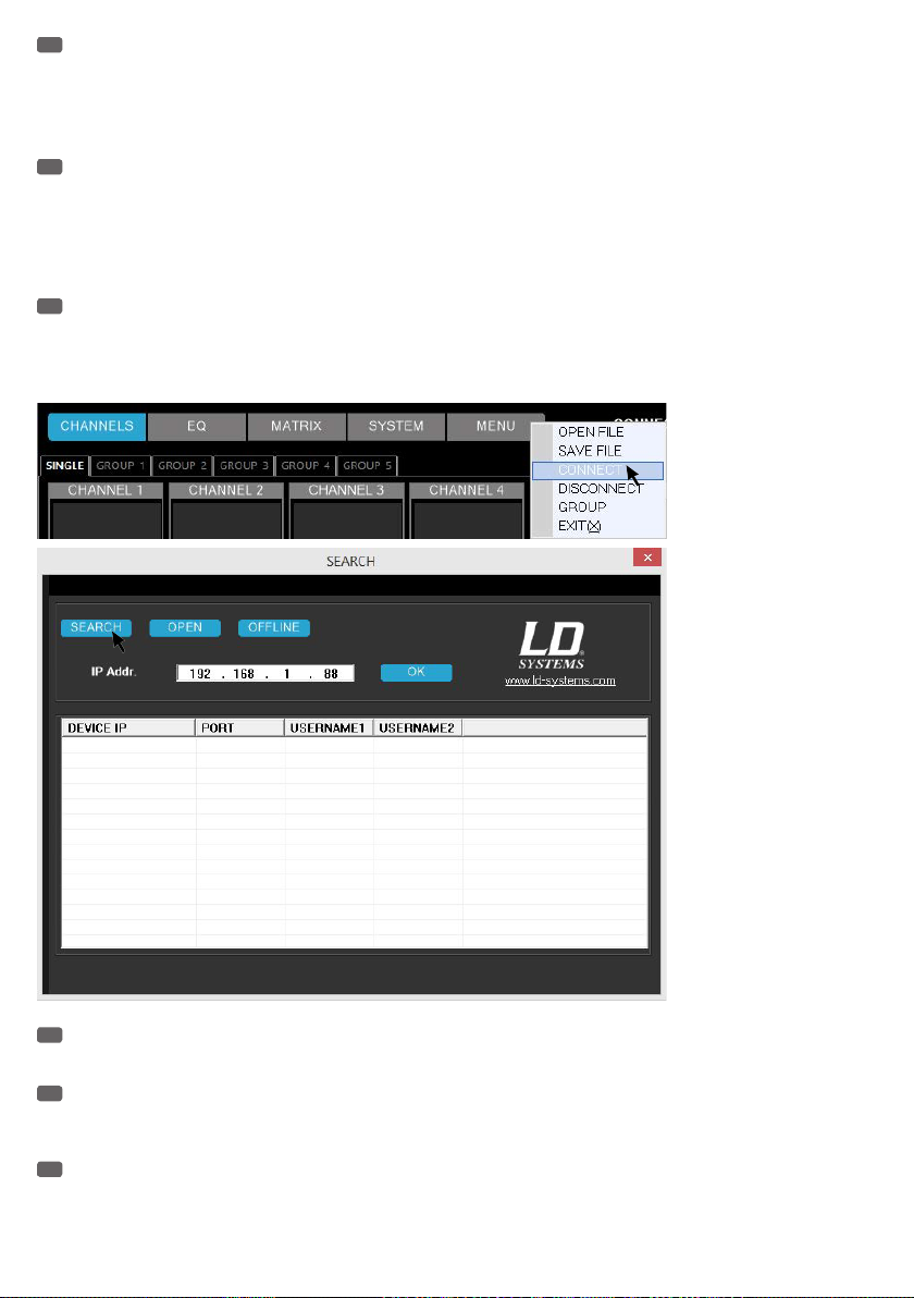
ES
Instale el software AUTOMIX8 en un PC con sistema operativo Windows (Windows Vista, WIN7, WIN8, resolución mínima de 1366x768) y conecte el mezclador automático AM8 mediante un cable LAN (CAT-5) al puerto Ethernet del ordenador. Como por defecto la dirección IP del mezclador
automático AM8 es 192.168.1.88, deberá asignar otra dirección IP al puerto del ordenador (ver la figura «Propiedades: Protocolo de Internet versión
4»). Ejecute el programa AUTOMIX8, haga clic en «MENU», y haga clic en «CONNECT» (conectar). En la ventana que se abre, haga clic en «SEARCH»
(buscar).
PL
Zainstalować oprogramowanie AUTOMIX8 na komputerze z systemem Windows (Vista, 7, 8) o minimalnej rozdzielczości ekranu 1366 × 768 i
podłączyć automatyczny mikser AM8 za pomocą kabla LAN (CAT-5) do złącza Ethernet komputera. Ponieważ fabrycznym adresem IP automatycznego
miksera AM8 jest adres 192.168.1.88, do użytego złącza komputera należy przypisać inny adres IP (patrz rysunek „Właściwości protokołu internetowego w wersji 4”). Uruchomić oprogramowanie AUTOMIX8, kliknąć lewym przyciskiem myszy „MENU”, przesunąć kursor myszy na opcję „CONNECT”
(POŁĄCZ), a następnie potwierdzić klikając ją lewym przyciskiem myszy. Kliknąć niebieskie pole „SEARCH” (SZUKAJ) w oknie, które właśnie się
otworzyło.
IT
Installare il software AUTOMIX8 su un PC con sistema operativo Windows (Windows Vista, WIN 7, WIN 8, risoluzione dello schermo min.1.366 x
768) e collegare il mixer automatico AM8 alla porta Ethernet del computer utilizzando un cavo LAN (CAT-5). Poiché l'indirizzo IP del mixer automatico
AM8 è preimpostato su 192.168.1.88, alla porta del computer utilizzata si deve assegnare un indirizzo IP diverso (v.immagine: "Proprietà - Protocollo
Internet Versione4"). Avviare il software AUTOMIX8, fare clic su "MENU", spostare il cursore su "CONNECT" (collegare) e confermare con un clic. Fare
clic su "SEARCH" (cercare) nella finestra che si è aperta.
EN
If all settings and connections are properly made, the connected device is displayed after a few seconds with its IP address and an INFO window
announcing "Search finished" (search completed) appears. Press "OK". To enter the user name (USER NAME) and password (USER PSW), now click on
the blue "OK" field. The factory preset password for the user "admin" and "user" is "000000" (six times the number zero). Press "OK".
DE
Wurden alle Einstellungen und Verbindungen korrekt durchgeführt, wird nach wenigen Sekunden das verbundene Gerät mit seiner IP-Adresse
angezeigt und ein INFO-Fenster mit mit dem Hinweis "Search finished" (Suche abgeschlossen) erscheint. Klicken Sie auf "OK". Um den Benutzernamen (USER NAME) und das Benutzerpasswort (USER PSW) einzugeben, klicken Sie nun auf das blaue Feld "OK". Das ab Werk voreingestellte Benutzerpasswort für die Benutzer "admin" und "user" ist jeweils "000000" (sechs mal die Zahl Null). Klicken Sie auf "OK".
FR
Si tous les réglages et branchements ont été effectués correctement, l'AM8 connecté apparaît à l'écran au bout de quelques secondes, avec son
adresse IP et une fenêtre INFO mentionnant "Search finished" (recherche terminée). Cliquez sur "OK". Pour pouvoir accéder aux champs USER NAME
(nom utilisateur) et USER PSW (mot de passe utilisateur), cliquez sur le champ bleu "OK". À la sortie d'usine, le mot de passe utilisateur pour "admin"
et "user" est réglé sur "000000" (six fois le chiffre zéro). Cliquez sur "OK".
28
Page 29

ES
Si la configuración y el cableado está correcto, al cabo de unos segundos se mostrarán los equipos conectados, su dirección IP y una ventana
INFO con el texto «Search finished» (Búsqueda finalizada). Haga clic en «OK» (Aceptar). Después de escribir el nombre de usuario (USER NAME) y la
contraseña (USER PSW), haga clic en el botón azul «OK». La contraseña por defecto de los usuarios «admin» y «user» es «000000» (seis ceros seguidos). Haga clic en «OK» (Aceptar).
PL
Jeżeli wszystkie ustawienia i połączenia zostały przeprowadzone poprawnie, po kilku sekundach w systemie widoczne będzie połączone urządzenie i jego adres IP oraz wyświetlone zostanie okno informacyjne zawierające informację „Search finished” (Szukanie ukończone). Kliknąć „OK”. W
celu podania nazwy użytkownika (USER NAME) oraz hasła użytkownika (USER PSW) należy teraz kliknąć niebieskie pole „OK”. Fabrycznie ustawionym
hasłem dla obu użytkowników („admin” i „user”) jest hasło „000000” (sześć cyfr zero). Kliknąć „OK”.
IT
Se tutte le impostazioni e i collegamenti sono stati eseguiti correttamente, dopo pochi secondi l'apparecchio collegato viene visualizzato con il
relativo indirizzo IP e appare una finestra INFO con la nota "Search finished" (ricerca terminata). Fare clic su "OK". Per inserire il nome utente (USER
NAME) e la password utente (USER PSW), fare clic su "OK". La password preimpostata per gli utenti "admin" e "user" è "000000" (sei zeri). Fare clic
su "OK".
EN
If several AM8 automatic mixers are daisy-chained, and should settings and control be operated by the AUTOMIX8 software, an individual IP address must be assigned to each individual automatic mixer. The mixers must be connected to the software one by one. While the IP address is changed,
the automatic mixer is restarted. After changing the IP address, you must restart the software and the device must be connected again. Use an Ethernet switch to connect several automatic mixers to a computer.
DE
Kaskadiert man mehrere der AM8 Automatik-Mixer und sollen Einstellungen und Kontrolle durch die AUTOMIX8 Software stattfinden, muss jedem
einzelnen Automatik-Mixer eine individuelle IP-Adresse zugewiesen werden. Die Mixer müssen dafür einzeln nacheinander mit der Software verbunden
werden. Während die IP-Adresse geändert wird, erfolgt ein Neustart des Automatik-Mixers. Nach dem Ändern der IP-Adresse, muss die Software neu
gestartet und das Gerät wieder verbunden werden. Verwenden Sie einen Ethernet Switch, um eine Verbindung mehrer Automatik-Mixer mit einem
Rechner herzustellen.
FR
Si vous avez cascadé plusieurs mixeurs automatiques AM8 et désirez pouvoir les contrôler séparément depuis le logiciel AUTOMIX8, il faut attribuer une adresse IP spécifique à chacun des AM8. Pour ce faire, il faut les connecter l'un après l'autre au PC sur lequel tourne le logiciel. Une fois
l'adresse IP modifiée, le mixeur automatique redémarre. Il faut ensuite relancer le logiciel, et réinsérer l'AM8 dans le système audio. Si vous utilisez
plusieurs mixeurs automatiques avec un même ordinateur, il faut les connecter en passant par un switch Ethernet.
ES
Si conecta en cascada varios mezcladores automáticos AM8 y utiliza el software AUTOMIX8 para la configuración y el control, deberá asignar una
dirección IP diferente a cada mezclador automático. Debe asociarse cada mezclador, uno a uno, al software. En el cambio de dirección IP, será necesario reiniciar el mezclador automático. Después de cambiar la dirección IP, deberá reiniciar el software para volver a conectar el equipo. Use un switch
Ethernet para conectar varios mezcladores automáticos a un ordenador.
PL
W przypadku kaskadowania kilku automatycznych mikserów AM8, wprowadzania ustawień i sterowania za pomocą oprogramowania AUTOMIX8
każdemu automatycznemu mikserowi należy przypisać indywidualny adres IP. W tym celu każdy z mikserów należy połączyć z oprogramowaniem z
osobna, tj. jeden po drugim. Podczas zmiany adresu IP następuje ponowne uruchomienie automatycznego miksera. Po zmianie adresu IP należy ponownie uruchomić oprogramowanie, a urządzenie musi zostać ponownie połączone. W celu połączenia kilku automatycznych mikserów z jednym
komputerem należy wykorzystać przełącznik Ethernet.
IT
Se si collegano a cascata vari mixer automatici AM8 e le impostazioni e i controlli devono essere effettuate con il software AUTOMIX8, a ogni
mixer automatico deve essere assegnato un diverso indirizzo IP. I mixer perciò devono essere collegati al software uno dopo l'altro. Quando si modifica
l'indirizzo IP, il mixer automatico deve essere riavviato. Una volta modificato l'indirizzo IP, è necessario riavviare il software e ricollegare l'apparecchio.
Utilizzare un interruttore Ethernet per collegare a un computer vari mixer automatici.
29
Page 30
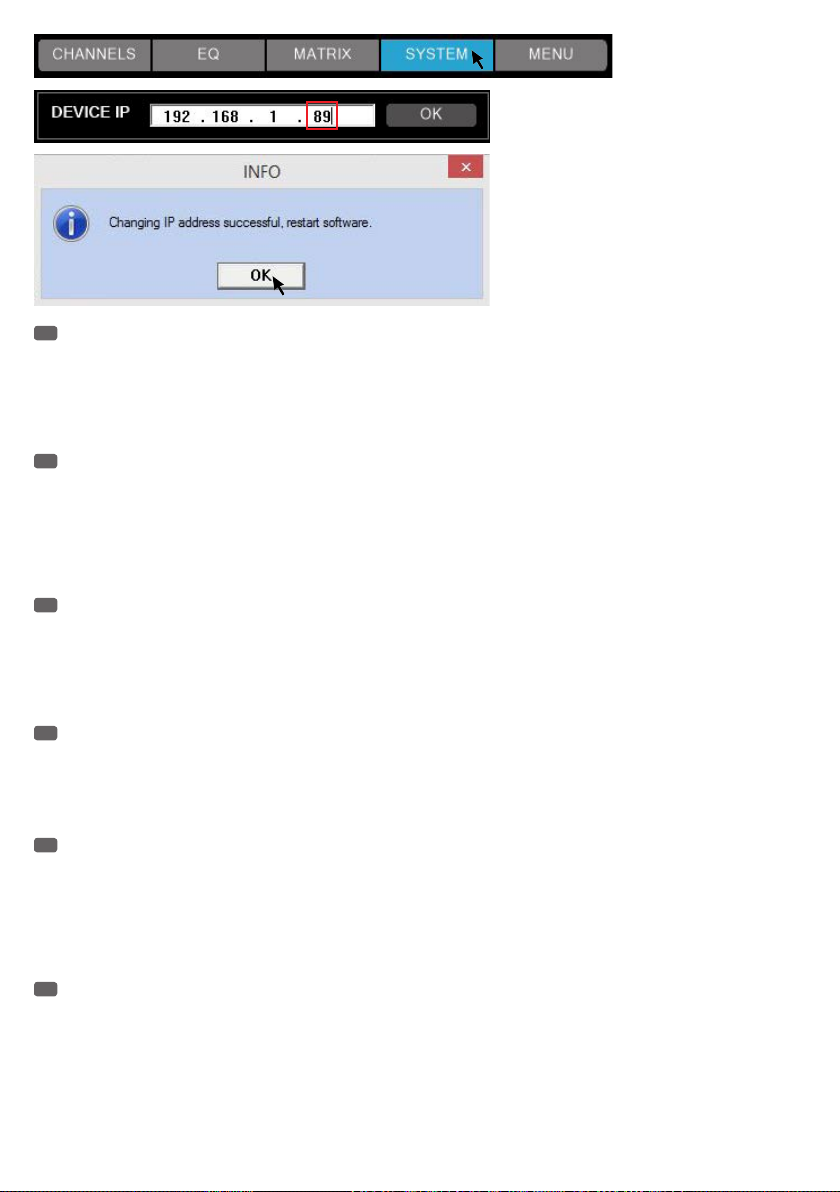
EN
Only one automatic mixer can be connected to the software at any time. To connect a different automatic mixer with the software, remove the
connection of the currently connected mixer by clicking on "MENU" and "DISCONNECT" (see figure). Now click on "MENU" and "CONNECT" to establish a connection with an automatic mixer with a different IP address. If all settings and connections are properly made, the connected devices are
displayed after a few seconds with their respective IP address and an INFO window announcing "Search finished" (search completed) appears. Press
"OK". Now select the desired device by clicking on the corresponding IP address, click on the blue "OK" field and type your user name and password
as usual.
DE
Es kann immer nur ein Automatik-Mixer aktuell mit der Software verbunden sein. Um einen anderen Automatik-Mixer mit der Software zu verbinden, lösen Sie die Verbindung des aktuell verbundenen Mixers, indem Sie auf "MENU" und "DISCONNECT" klicken (siehe Abbildung). Klicken Sie
nun auf "MENU" und "CONNECT", um eine Verbindung mit einem Automatik-Mixer mit einer anderen IP-Adresse herzustellen. Wurden alle Einstellungen und Verbindungen korrekt durchgeführt, werden nach wenigen Sekunden die Geräte, die mit dem Rechner verbunden sind, mit der entsprechenden IP-Adresse angezeigt und ein INFO-Fenster mit mit dem Hinweis "Search finished" (Suche abgeschlossen) erscheint. Klicken Sie auf "OK". Wählen
Sie nun das gewünschte Gerät durch Klicken auf die entsprechende IP-Adresse aus, klicken auf das blaue Feld "OK" und geben dann wie gewohnt
Ihren Benutzernamen und das Passwort ein.
FR
Le logiciel ne peut communiquer qu'avec un seul mixeur automatique à un moment donné. Dès que vous reliez un autre mixeur automatique au
logiciel, vous perdez la liaison avec le mixeur déjà relié, puisqu'il vous faut cliquer sur "MENU" et "DISCONNECT" (voir illustration). Cliquez ensuite sur
"MENU" et "CONNECT" pour établir la liaison avec l'autre mixeur automatique, pourvu d'une adresse IP différente. Si tous les réglages et branchements ont été effectués correctement, l'AM8 connecté apparaît à l'écran au bout de quelques secondes, avec son adresse IP et une fenêtre INFO
mentionnant "Search finished" (recherche terminée). Cliquez sur "OK". Choisissez alors l'appareil désiré en cliquant sur l'adresse IP correspondante,
puis cliquez sur le champ bleu "OK" et entrez, comme d'habitude, votre nom d'utilisateur et votre mot de passe.
ES
Es posible tener conectado un único mezclador automático al software. Para conectar otro mezclador automático al software, haga clic en
«MENU» «DISCONNECT» para desconectar el mezclador actualmente conectado (ver figura). A continuación, haga clic en «MENU» y «CONNECT» para
conectar un mezclador automático con otra dirección IP. Si la configuración y el cableado está correcto, al cabo de unos segundos se mostrarán los
equipos conectados al PC, su dirección IP y una ventana INFO con el texto «Search finished» (Búsqueda finalizada). Haga clic en «OK» (Aceptar). Haga
clic en una dirección IP para seleccionar el equipo, haga clic en el botón azul «OK» y escriba el nombre de usuario y la contraseña.
PL
Każdorazowo w danej chwili z oprogramowaniem może być połączony tylko jeden automatyczny mikser. W celu połączenia z oprogramowaniem
innego automatycznego miksera należy przerwać połączenie z aktualnie połączonym mikserem klikając „MENU” i „DISCONNECT” (patrz rysunek). W
celu nawiązania połączenia z automatycznym mikserem o innym adresie IP należy teraz kliknąć „MENU” i „CONNECT”. Jeżeli wszystkie ustawienia i
połączenia zostały przeprowadzone poprawnie, po kilku sekundach w systemie widoczne będą połączone z komputerem urządzenia i odpowiadające
im adresy IP oraz wyświetlone zostanie okno informacyjne zawierające informację „Search finished” (Szukanie ukończone). Kliknąć „OK”. Teraz należy wybrać żądane urządzenie klikając odpowiadający mu adres IP, kliknąć niebieskie pole „OK”, a następnie zgodnie ze standardową procedurą podać
swoją nazwę użytkownika i hasło.
IT
Al software è possibile collegare un solo mixer automatico. Per collegare al software un altro mixer automatico, fare clic su "MENU" e "DISCONNECT" (v. immagine) per disattivare il mixer attualmente connesso. Ora fare clic su "MENU" e "CONNECT" per stabilire una connessione tra il mixer
automatico con un indirizzo IP diverso. Se tutte le impostazioni e i collegamenti sono stati eseguiti correttamente, dopo pochi secondi gli apparecchi
collegati al computer vengono visualizzati con i relativi indirizzi IP e appare una finestra INFO con la nota "Search finished" (ricerca terminata). Fare
clic su "OK". Selezionare ora l'apparecchio desiderato facendo clic sull'indirizzo IP corrispondente, fare clic su "OK" e inserire quindi il nome utente e
la password come di consueto.
30
Page 31

SOFTWARE MAIN WINDOW / SOFTWARE HAUPTFENSTER / FENÊTRE PRINCIPALE DU LOGICIEL /
VENTANA PRINCIPAL DEL PROGRAMA / GŁÓWNE OKNO PROGRAMU / FINESTRA PRINCIPALE DEL
SOFTWARE
1 2 3 4 5 6
7
8
9 9
10
12
13
11
14
16
18
21
1
CHANNELS
EN
Overview of the input channels (CHANNEL 1 - 8) and the line outputs (MASTER 1 & 2).
DE
Übersicht der Eingangs-Kanäle (CHANNEL 1 - 8) und der Line-Ausgänge (MASTER 1 & 2).
FR
Vue globale des canaux d'entrée (CHANNEL 1 - 8) et des sorties (MASTER 1 & 2).
15
17
2019
22
31
Page 32

ES
Vista general de los canales de entrada (CHANNEL1 - 8) y salidas de línea (MASTER1 y 2).
PL
Przegląd kanałów wejściowych (KANAŁY 1–8) i wyjść liniowych (MASTER 1 I 2).
IT
Panoramica dei canali d'ingresso (CHANNEL1 - 8) e delle uscite di linea (MASTER1 e 2).
2
EQ
EN
Equalizer setting for the input channels and channel groups (GROUP 1-5).
DE
Equalizer-Einstellung der Eingangs-Kanäle und der Kanal-Gruppen (GROUP 1 - 5).
FR
Paramètres des égaliseurs des canaux d'entrée et des groupes de canaux (GROUP 1 - 5).
ES
Ecualizador de los canales de entrada y grupos de canales (GROUP1 - 5).
PL
Ustawienie korektora dźwięku kanałów wejściowych i grup kanałów (GRUPY 1–5).
IT
Impostazioni dell'equalizzatore dei canali di ingresso e dei gruppi di canali (GROUP1 - 5).
3
MATRIX
EN
Individual routing for the input channels (CHANNEL 1 - 8) and the line outputs (MASTER 1 & 2).
DE
Individuelles Routen der Eingangs-Kanäle (CHANNEL 1 - 8) auf die Line-Ausgänge (MASTER 1 & 2).
FR
Assignation individuelle des canaux d'entrée (CHANNEL 1 - 8) aux sorties (MASTER 1 & 2).
ES
Asignación de los canales de entrada (CHANNEL1 - 8) a las salidas de línea (MASTER1 y 2).
PL
Indywidualne przetrasowywanie kanałów wejściowych (KANAŁY 1–8) na wyjścia liniowe (MASTER 1 I 2).
IT
Instradamento dei canali d'ingresso (CHANNEL1 - 8) nelle uscite di linea (MASTER1 e 2).
4
SYSTEM
EN
Setting the threshold value for activating a channel (THRESHOLD), the hold time (HOLD TIME), the locking of the controls (PANEL LOCK), the
configuration as master or slave unit (DEVICE MODE), the maximum number of open channels (MAX. OPEN CH), the IP address (DEVICE IP), managing
the password (USER) and resetting the unit (FACTORY SETTINGS).
DE
Einstellung des Schwellenwerts für die Aktivierung eines Kanals (THRESHOLD), der Haltezeit (HOLD TIME), der Sperrung der Bedienelemente
(PANEL LOCK), der Konfigurierung als Master- oder Slave-Einheit (DEVICE MODE), der maximalen Anzahl der offenen Kanäle (MAX. OPEN CH), der
IP-Adresse (DEVICE IP), der Verwaltung von Passwort (USER) und Zurücksetzen des Geräts (FACTORY SETTINGS).
FR
Réglage de la valeur de seuil d'activation d'un canal (THRESHOLD), de la durée de maintien (HOLD TIME), verrouillage des commandes (PANEL
LOCK), configuration en mode Master ou Slave-(DEVICE MODE), réglage du nombre maximal de canaux ouverts (MAX. OPEN CH), de l'adresse IP
(DEVICE IP), gestion du mot de passe (USER) et réinitialisation de l'appareil (FACTORY SETTINGS).
ES
Permite ajustar el nivel umbral para activar los canales (THRESHOLD), el tiempo de mantenimiento (HOLD TIME), el bloqueo de los controles
(PANEL LOCK), el establecimiento del equipo como maestro o esclavo (DEVICE MODE), el número máximo de canales abiertos (MAX. OPEN CH), la
dirección IP (DEVICE IP), la gestión de contraseñas (USER) y el restablecimiento del equipo a los valores de fábrica (FACTORY SETTINGS).
PL
Ustawienie wartości progowej aktywowania kanału (THRESHOLD), czas wstrzymania (HOLD TIME), blokada elementów obsługi (PANEL LOCK),
ustawienie w trybie urządzenia głównego lub podporządkowanego (DEVICE MODE), maksymalna liczba otwartych kanałów (MAX. OPEN CH), adres IP
(DEVICE IP), zarządzanie hasłem (USER) oraz przywracanie ustawień fabrycznych urządzenia (FACTORY SETTINGS).
IT
Impostazione del valore soglia per l'attivazione di un canale (THRESHOLD), del periodo di sospensione (HOLD TIME), del blocco dei controlli
(PANEL LOCK), della configurazione dell'apparecchio come master o slave (DEVICE MODE), del numero massimo di canali aperti (MAX. OPEN CH),
dell'indirizzo IP(DEVICE IP), della gestione della password (USER) e del ripristino dei valori di fabbrica dell'apparecchio (FACTORY SETTINGS).
5
MENU
EN
Saving and recalling user settings (SAVE FILE / OPEN FILE), connecting and disconnecting a connection (CONNECT / DISCONNECT), managing
the channel group (GROUP) and exiting the program (EXIT).
DE
Sichern und Aufrufen von Benutzer-Einstellungen (SAVE FILE / OPEN FILE), Herstellen und Trennen einer Verbindung (CONNECT / DISCONNECT),
Verwalten der Kanal-Gruppen (GROUP) und Beenden des Programms (EXIT).
FR
Exportation/importation de fichiers de paramètres utilisateur (SAVE FILE / OPEN FILE), établissement/fin d'une liaison PC (CONNECT /
DISCONNECT), gestion des groupes de canaux (GROUP) et quitter le programme (EXIT).
ES
Permite guardar y abrir la configuración de usuario (SAVE FILE / OPEN FILE), conectar o desconectar (CONNECT / DISCONNECT), gestionar los
grupos de canales (GROUP) y salir del programa (EXIT).
PL
Zapisywanie i otwieranie ustawień użytkownika (SAVE FILE/OPEN FILE), nawiązywanie i kończenie połączenia (CONNECT/DISCONNECT),
zarządzanie grupami kanałów (GROUP) oraz zamykanie programu (EXIT).
IT
Salvataggio e apertura delle impostazioni utente (SAVE FILE / OPEN FILE), attivazione e disattivazione di un collegamento (CONNECT /
DISCONNECT), gestione dei gruppi di canali (GROUP) e conclusione del programma (EXIT).
6
CONNECTION ON / OFF
EN
If the "ON" button is highlighted in yellow, the connection between automixer and computer is established. If the "OFF" button is highlighted in
yellow, the connection between automixer and computer is severed.
DE
Wird die Anzeigefläche "ON" gelb hervorgehoben, ist die Verbindung zwischen Automixer und Rechner hergestellt. Wird die Anzeigefläche
32
Page 33

"OFF" gelb hervorgehoben, ist die Verbindung zwischen Automixer und Rechner getrennt.
FR
Si l'indicateur "ON" apparaît en jaune, la liaison est établie entre l'AM8 et l'ordinateur. Si l'indicateur "OFF" apparaît en jaune, la liaison est
coupée entre l'AM8 et l'ordinateur.
ES
Si «ON» está sobre un fondo amarillo, indica que hay conexión entre el mezclador automático y el ordenador. Si «OFF» está sobre un fondo
amarillo, no hay conexión entre el mezclador automático y el ordenador.
PL
Wyróżnienie kolorem żółtym wyświetlanego obszaru „ON” oznacza, że połączenie pomiędzy automatycznym mikserem a komputerem zostało
nawiązane. Wyróżnienie kolorem żółtym wyświetlanego obszaru „OFF” oznacza, że połączenie pomiędzy automatycznym mikserem a komputerem
zostało przerwane.
IT
Se lo sfondo del pulsante "ON" è di colore giallo, significa che il collegamento tra il mixer automatico e il computer è stabilito. Se lo sfondo del
pulsante "OFF" è di colore giallo, significa che il collegamento tra il mixer automatico e il computer è disattivato.
7
SINGLE / GROUP 1 - 5
EN
Showing the input channels that are not associated with a channel group (SINGLE), and showing the channel groups (GROUP 1-5).
DE
Aufrufen der Eingangs-Kanäle, die nicht einer Kanal-Gruppe zugeordnet sind (SINGLE), und Aufrufen der Kanal-Gruppen (GROUP 1 - 5).
FR
Appel des canaux d'entrée ne faisant pas partie d'un groupe de canaux (SINGLE) et appel des groupes de canaux (GROUP 1 - 5).
ES
Muestra los canales de entrada que no están asignados a ningún grupo de canales (SINGLE), o los grupos de canales (GROUP1 - 5).
PL
Otwieranie kanałów wejściowych, które nie zostały przyporządkowane do żadnej grupy kanałów (SINGLE) oraz otwieranie grup kanałów
(GROUP 1–5).
IT
Visualizzazione dei canali d'ingresso non attribuiti a un gruppo di canali (SINGLE) e dei gruppi di canali (GROUP1 - 5).
8
CHANNEL 1 - 8
EN
By double-clicking, the name of the channel can be changed individually.
DE
Durch Doppelklick kann die Kanal-Bezeichnung individuell geändert werden.
FR
Double-cliquez pour modifier individuellement le nom du canal.
ES
Haga doble clic para cambiar el nombre de un canal.
PL
Nazwy poszczególnych kanałów można zmieniać za pomocą podwójnego kliknięcia.
IT
Per modificare il nome di un canale, fare doppio clic.
9
EQUALIZER
EN
Graphical representation of the equalizer setting and button to access the 5-band parametric equalizer of the input channels 1 to 8 or 15-band
parametric equalizer of the output channels Master 1 and 2 (single click with the left mouse button).
DE
Grafische Darstellung der Equalizer-Einstellung und Schaltfläche zum Aufrufen der 5-Band Parametrik-Equalizer der Eingangs-Kanäle 1 bis 8
bzw. 15-Band Parametrik-Equalizer der Ausgangs-Kanäle Master 1 und 2 (einfacher Klick mit der linken Maustaste).
FR
Représentation graphique de la courbe de réponse et activation de l'égaliseur paramétrique 5 bandes sur les canaux d'entrée 1 à 8 et de
l'égaliseur paramétrique 15 bandes des canaux de sortie Master 1 et Master 2 (clic sur la courbe).
ES
Ecualizador gráfico y botón para mostrar el ecualizador paramétrico de 5bandas de los canales de entrada 1 a 8 o el ecualizador paramétrico
de 15bandas de los canales de salida Master1 y 2 (con un clic de ratón).
PL
Graficzne przedstawienie ustawień korektora dźwięku i przycisk otwierający pięciopasmowy parametryczny korektor dźwięku kanałów
wejściowych od 1 do 8 oraz piętnastopasmowy parametryczny korektor dźwięku kanałów wyjściowych Master 1 i 2 (wystarczy kliknąć lewym
przyciskiem myszy).
IT
Raffigurazione grafica delle impostazioni dell'equalizzatore e del pulsante che consente di mostrare l'equalizzatore parametrico a 5bande dei
canali di ingresso da 1 a 8 l'equalizzatore parametrico a 15bande dei canali di uscita Master1 e 2 (un clic del tasto sinistro del mouse).
10
LINE / MIC CHANNEL 1 - 8
EN
Switching the input channels from line to microphone sensitivity and vice versa (single click with the left mouse button). The yellow-highlighted
button shows the option currently active.
DE
Umschalten der Eingangs-Kanäle von Line- auf Mikrofon-Empfindlichkeit und umgekehrt (einfacher Klick mit der linken Maustaste). Die gelb
hervorgehobene Schalt- und Anzeigefläche zeigt die jeweils aktivierte Option an.
FR
Sélection du niveau de travail (Ligne ou Micro) sur chaque entrée, par simple clic. L'indicateur/sélecteur jaune indique l'option activée.
ES
Permite cambiar la sensibilidad de los canales de entrada de línea a micro, y viceversa (con un clic de ratón). El color amarillo de los botones
indica la opción activa.
PL
Przełączanie czułości kanałów wejściowych z odpowiedniej dla sygnału liniowego na właściwą dla sygnału mikrofonowego i odwrotnie
(wystarczy kliknąć lewym przyciskiem myszy). Przycisk i wyświetlany obszar wyróżnione kolorem żółtym informują o aktywnej w danej chwili opcji.
IT
Commutazione della sensibilità dei canali d'ingresso da linea a microfono e viceversa (un solo clic del mouse). I pulsanti in giallo indicano qual
è l'opzione attiva.
33
Page 34

11
LINE / MIC MASTER 1 & 2
EN
Switching the output level of the line outputs Master 1 and Master 2 (single click with the left mouse button). The blue-highlighted button
shows the option currently active (LINE = output signal with line level, e.g. for the line input of a power amplifier / MIC = output signal level
attenuated by 20 dB, for example for the microphone input of a mixer).
DE
Umschalten des Ausgangs-Pegels der Line-Ausgänge Master 1 und Master 2 (einfacher Klick mit der linken Maustaste). Die blau hervorgehobene Schalt- und Anzeigefläche zeigt die jeweils aktivierte Option an (LINE = Ausgangs-Signal mit Line-Pegel, z.B. für den Line-Eingang einer
Endstufe / MIC = Ausgangs-Signal mit um 20 dB reduziertem Pegel, z.B. für den Mikrofon-Eingang eines Mischpults).
FR
Sélection du niveau de travail sur la sortie Master 1 et Master 2, par simple clic. L'indicateur/sélecteur bleu visualise l'option activée (LINE =
signal de sortie au niveau ligne, par exemple pour branchement à un amplificateur ; MIC = signal de sortie atténué de 20 dB par rapport au niveau
ligne, par exemple pour branchement sur l'entrée micro d'une console de mixage).
ES
Permite cambiar el nivel de salida de las salidas de línea Master1 y Master2 (con un clic de ratón). El color azul de los botones indica la
opción activa (LINE= señal de salida con nivel de línea, por ejemplo, para la entrada de línea de un amplificador; MIC= señal de salida con nivel
atenuado 20dB, por ejemplo, para una entrada de micrófono de una mesa de mezclas).
PL
Przełączanie poziomów wyjściowych wyjść liniowych Master 1 i 2 (wystarczy kliknąć lewym przyciskiem myszy). Przycisk i wyświetlany obszar
wyróżnione kolorem niebieskim informują o aktywnej w danej chwili opcji (LINE = sygnał wyjściowy o liniowym poziomie, np. dla wejścia liniowego
końcówki mocy/MIC = sygnał wyjściowy o obniżonym o 20 dB poziomie, np. dla wejścia mikrofonowego stołu mikserskiego).
IT
Commutazione del livello di uscita delle uscite di linea Master1 e Master2 (semplice clic del mouse). I pulsanti di colore azzurro indicano
l'opzione attiva (LINE= segnale di uscita con livello di linea, ad esempio per l'ingresso di linea di un finale di potenza; MIC= segnale di uscita con
livello attenuato di 20dB, ad esempio per l'ingresso del microfono di un mixer).
12
ACTIVE / WAITING
EN
The yellow-highlighted "ACTIVE" button indicates which of the input channels is activated. If a channel is not activated, the message
"WAITING" is greyed out on the screen. By activating the priority function, the corresponding channel is activated permanently.
DE
Die gelb hervorgehobene Anzeigefläche "ACTIVE" zeigt an, welcher der Eingangs-Kanäle aktiviert ist. Ist ein Kanal nicht aktiviert, erscheint
"WAITING" auf der Anzeigefläche grau hinterlegt. Durch Aktivierung der Prioritäts-Funktion, wird der entsprechende Kanal permanent aktiviert.
FR
L'indicateur/sélecteur jaune "ACTIVE" visualise les canaux d'entrée activés. Sur un canal non activé, cet indicateur devient gris, avec la
mention "WAITING". Si la fonction Priorité est activée, alors le canal correspondant est activé en permanence.
ES
El color amarillo en «ACTIVE» indica el canal de entrada activo. Si un canal no está activado, se mostrará «WAITING» sobre fondo gris. Mediante
la función Prioridad, el canal permanece siempre activo.
PL
Wyróżniony żółtym kolorem wyświetlany obszar „ACTIVE” informuje o tym, który z kanałów wejściowych jest aktywny. W przypadku gdy dany
kanał jest nieaktywny wyświetlany obszar zawiera wyróżniony kolorem szarym komunikat „WAITING”. Po włączeniu funkcji przydzielania priorytetu
odpowiedni kanał będzie stale pozostawał aktywny.
IT
Il pulsante "ACTIVE" di colore giallo indica che il canale d'ingresso è attivo. Se un canale non è attivo, sul pulsante appare "WAITING" su fondo
grigio. Attivando la funzione PRIORITY, il canale corrispondente rimane attivo.
13
LEVEL METER CHANNEL 1 - 8 / MASTER 1 & 2 / PEGELANZEIGE CHANNEL 1 - 8 / MASTER 1 & 2 / INDICATEURS DE NIVEAU CHANNEL
1 - 8 / MASTER 1 & 2 / VÚMETRO CHANNEL 1 - 8 / MASTER 1 Y 2 / WSKAŹNIK POZIOMU KANAŁÓW 1–8/MASTER 1 I 2 / INDICATORE
DI LIVELLO CHANNEL 1 - 8 / MASTER 1 E 2
EN
The level meters for the input channels 1 to 8 and the line outputs Master 1 and 2 provide a clear overview of the levels.
DE
Die Pegelanzeigen für die Eingangs-Kanäle 1 bis 8 und die Line-Ausgänge Master 1 und 2 liefern eine klare Übersicht der Pegelverhältnisse.
FR
Les indicateurs de niveau des canaux d'entrée 1 à 8 et des sorties Master 1 et 2 donnent une idée de l'activité des signaux audio sur l'AM8.
ES
Los vúmetros de los canales de entrada1-8 y de las salidas de la línea Master1 y 2 indican claramente los niveles.
PL
Wskaźniki poziomu kanałów wejściowych od 1 do 8 oraz wyjścia liniowego Master 1 i 2 dają jasny przegląd porównawczy poszczególnych
poziomów.
IT
Gli indicatori di livello dei canali d'ingresso da 1 a 8 e le uscite di linea Master1 e 2 indicano chiaramente i livelli.
14
PRIORITY
EN
Button for the priority function of the input channels. By clicking on the "PRIORITY" button, the corresponding channel is given priority over the
other channels. The button will change its colour to yellow. By re-clicking on "PRIORITY", the priority function is disabled.
DE
Schalt- und Anzeigefläche für die Prioritäts-Funktion der Eingangs-Kanäle. Durch Klicken auf die Schalfläche "PRIORITY" wird dem
entsprechenden Kanal Vorrang vor den anderen Kanälen gegeben. Die Anzeigefläche wechselt ihre Farbe auf Gelb. Durch nochmaligen Klicken auf
"PRIORITY" wird die Prioritäts-Funktion deaktiviert.
FR
Sélecteur/indicateur de la fonction Priority sur le canal d'entrée Cliquer sur l'indicateur/sélecteur "PRIORITY" rend le canal correspondant
prioritaire sur les autres canaux. L'indicateur passe alors au jaune. Pour désactiver la fonction "PRIORITY", cliquez de nouveau sur l'indicateur.
ES
Botones de la función Prioridad de los canales de entrada. Haga clic en «PRIORITY» para que el canal tenga prioridad sobre el resto de canales.
El color del fondo cambiará a amarillo. Haga clic de nuevo en «PRIORITY» para desactivar la función.
PL
Przycisk i wyświetlany obszar funkcji przydzielania priorytetu kanałów wejściowych. Kliknięcie przycisku „PRIORITY” spowoduje przydzielenie
priorytetu odpowiedniemu kanałowi w stosunku do pozostałych kanałów. Wyświetlany obszar zmieni kolor na żółty. Po ponownym kliknięciu
przycisku „PRIORITY” funkcja przydzielania priorytetu zostanie dezaktywowana.
34
Page 35

IT
Pulsanti di attivazione e visualizzazione della funzione Priorità dei canali d'ingresso. Fare clic sul pulsante "PRIORITY" di un canale per
assegnare la priorità a tale canale rispetto agli altri. Il colore del pulsante passa a giallo. Facendo di nuovo clic su "PRIORITY" la funzione di priorità si
disattiva.
15
MASTER EQ MASTER 1 & 2
EN
Button to access the 15-band parametric equalizer of the output channels Master 1 and 2 (single click with the left mouse button).
DE
Schaltfläche zum Aufrufen der 15-Band Parametrik-Equalizer der Ausgangs-Kanäle Master 1 und 2 (einfacher Klick mit der linken Maustaste).
FR
Indicateur/sélecteur de l'égaliseur paramétrique 15 bandes sur les sorties Master 1 et 2.
ES
Botón para mostrar el ecualizador paramétrico de 15bandas de los canales de salida Master1 y 2 (con un clic de ratón).
PL
Przycisk otwierający piętnastopasmowy parametryczny korektor dźwięku kanałów wyjściowych Master 1 i 2 (wystarczy kliknąć lewym
przyciskiem myszy).
IT
Pulsante per la visualizzazione degli equalizzatori parametrici a 15bande dei canali di uscita Master1 e 2 (un clic con il mouse).
16
PHANTOM CHANNEL 1 - 8
EN
Button for the 48 V phantom power of the input channels. By clicking on the "PHANTOM" button, the phantom power of the corresponding
channel is enabled or disabled. If the phantom power is enabled, the button is highlighted in yellow, if the phantom power is disabled, the button is
greyed out.
DE
Schalt- und Anzeigefläche für die 48V Phantomspeisung der Eingangs-Kanäle. Durch Klicken auf die Schalfläche "PHANTOM" wird die
Phantomspeisung des entsprechenden Kanals aktiviert bzw. deaktiviert. Ist die Phantomspeisung aktiviert, wird die Anzeigefläche gelb hervorgehoben, ist die Phantomspeisung deaktiviert, wird die Anzeigefläche grau hinterlegt dargestellt.
FR
Indicateur/sélecteur de la tension d'alimentation fantôme 48 V sur les canaux d'entrée. Il suffit de cliquer sur le bouton "PHANTOM" pour
activer/désactiver la tension d'alimentation fantôme sur le canal correspondant. Lorsque l'alimentation fantôme est activée, l'indicateur passe en
jaune ; lorsqu'elle est désactivée, il passe au gris.
ES
Botones de la alimentación fantasma de 48V de los canales de entrada. Haga clic en «PHANTOM» para activar o desactivar la alimentación
fantasma del canal. Si la alimentación fantasma está activa, el fondo del botón será de color amarillo; si la alimentación fantasma está desactivada,
el fondo será gris.
PL
Przycisk i wyświetlany obszar 48 V zasilania phantom kanałów wejściowych. Kliknięcie przycisku „PHANTOM” spowoduje aktywowanie/
dezaktywowanie zasilania phantom odpowiedniego kanału. Jeżeli zasilanie phantom zostanie aktywowane, wyświetlany obszar zostanie wyróżniony
kolorem żółtym (lub szarym w przypadku dezaktywacji).
IT
Pulsanti di attivazione e visualizzazione dell'alimentazione phantom 48V dei canali d'ingresso. Facendo clic sul pulsante "PHANTOM" si attiva e
disattiva l'alimentazione phantom del canale corrispondente. Con l'alimentazione phantom attivata, il colore del pulsante è giallo, altrimenti è grigio.
17
LIMITER MASTER 1 & 2
EN
Button to access the limiter for the output channels Master 1 and 2 (single click with the left mouse button).
DE
Schaltfläche zum Aufrufen der Limiter für die Ausgangs-Kanäle Master 1 und 2 (einfacher Klick mit der linken Maustaste).
FR
Indicateur/sélecteur du limiteur des sorties Master 1 et Master 2.
ES
Botón para mostrar el limitador de los canales de salida Master1 y 2 (con un clic de ratón).
PL
Przycisk otwierający limiter kanałów wyjściowych Master 1 i 2 (wystarczy kliknąć lewym przyciskiem myszy).
IT
Pulsante per la visualizzazione dei limitatori dei canali di uscita Master1 e 2 (un clic con il mouse).
18
MUTE CHANNEL 1 - 8 / MASTER 1 & 2
EN
Button for the mute function of the input channels 1 to 8 and the line outputs Master 1 and 2. By clicking on the "MUTE" button, the mute
function of the corresponding channel is enabled or disabled. If the mute function is enabled, the button is highlighted in red, if the mute function is
disabled, the button is greyed out.
DE
Schalt- und Anzeigefläche für die Mute-Funktion der Eingangs-Kanäle 1 bis 8 und der Line-Ausgänge Master 1 und 2. Durch Klicken auf die
Schalfläche "MUTE" wird die Stummschaltung des entsprechenden Kanals aktiviert bzw. deaktiviert. Ist die Stummschaltung aktiviert, wird die
Anzeigefläche rot hervorgehoben, ist die Stummschaltung deaktiviert, wird die Anzeigefläche grau hinterlegt dargestellt.
FR
Indicateur/sélecteur de la fonction Mute des canaux d'entrée 1 à 8 et des sorties Master 1 et 2. Il suffit de cliquer sur le bouton "MUTE" pour
couper/rétablir le canal correspondant. Lorsque la fonction MUTE est activée, le bouton passe au rouge ; lorsqu'elle est désactivé, il passe au gris.
ES
Botones para silenciar los canales de entrada1 a 8 y las salidas de línea Master1 y 2. Haga clic en «MUTE» para silenciar o no el canal. Si la
función está activa, el fondo del botón será de color amarillo; si la alimentación fantasma está desactivada, el fondo será gris.
PL
Przycisk i wyświetlany obszar funkcji wyciszenia kanałów wejściowych od 1 do 8 oraz wyjść liniowych Master 1 i 2. Kliknięcie przycisku
„MUTE” spowoduje aktywowanie/dezaktywowanie funkcji wyciszenia odpowiedniego kanału. Jeżeli funkcja wyciszenia zostanie aktywowana,
wyświetlany obszar zostanie wyróżniony kolorem czerwonym (lub szarym w przypadku dezaktywacji).
IT
Pulsanti per silenziare i canali di ingresso da 1 a 8 delle uscite di linea Master1 e 2. Facendo clic sul pulsante "MUTE" per attivare e disattivare
la funzione di silenziamento del canale. Con il silenziamento attivato, il colore del pulsante è giallo, altrimenti è grigio.
35
Page 36

19
GAIN CHANNEL 1 - 8
EN
Set the input gain of the input channels using the mouse (click, hold, and drag).
DE
Stellen Sie die Eingangsvorverstärkung der Eingangs-Kanäle mit Hilfe der Computermaus ein (Klicken, Halten und Ziehen).
FR
Le réglage du gain du préampli du canal d'entrée s'effectue par l'intermédiaire de la souris (cliquer, maintenir enfoncé et faire glisser le
curseur).
ES
Ajuste la ganancia de los canales de entrada mediante el ratón (haga clic y arrastre).
PL
Ustawić wstępne wzmocnienie wejścia kanałów wejściowych za pomocą myszy komputera (kliknąć, przytrzymać i przeciągnąć).
IT
Impostare la preamplificazione dei canali d'ingresso con il mouse del computer (fare clic, tenere premuto e trascinare).
20
GAIN MASTER 1 & 2
EN
Set the output gain of the line outputs Master 1 and 2 using the mouse (click, hold, and drag).
DE
Stellen Sie die Ausgangsverstärkung der Line-Ausgänge Master 1 und 2 mit Hilfe der Computermaus ein (Klicken, Halten und Ziehen).
FR
Le réglage du gain des sorties Master 1 et Master 2 s'effectue par l'intermédiaire de la souris (cliquer, maintenir enfoncé et faire glisser le
curseur).
ES
Ajuste la ganancia de los canales de salida Master1 y 2 mediante el ratón (haga clic y arrastre).
PL
Ustawić wzmocnienie wyjścia wyjść liniowych Master 1 i 2 za pomocą myszy komputera (kliknąć, przytrzymać i przeciągnąć).
IT
Impostare la preamplificazione delle uscite di linea Master1 e 2 con il mouse del computer (fare clic, tenere premuto e trascinare).
21
GAIN ANZEIGE CHANNEL 1 - 8
EN
Displays the input gain of the input channels 1 to 8 in dB.
DE
Anzeige der Eingangsvorverstärkung der Eingangs-Kanäle 1 bis 8 in dB.
FR
Indicador de la ganancia de los canales de entrada1 a 8 en dB.
ES
Indicador de la ganancia de los canales de entrada1 a 8 en dB.
PL
Wskaźnik wstępnego wzmocnienia wejścia kanałów wejściowych 1 do 8 w dB.
IT
Visualizzazione della preamplificazione dei canali d'ingresso da 1 a 8 in dB.
22
GAIN ANZEIGE MASTER 1 & 2
EN
Displays the output gain of the line outputs Master 1 and 2 in dB.
DE
Anzeige der Ausgangsverstärkung der Line-Ausgänge Master 1 und 2 in dB.
FR
Visualisation numérique de la valeur de gain sur les sorties Master 1 et 2, en dB.
ES
Indicador de ganancia de las salidas de línea Master1 y 2 en dB.
PL
Wskaźnik wzmocnienia wyjścia wyjść liniowych Master 1 i 2 w dB.
IT
Visualizzazione dell'amplificazione delle uscite di linea Master1 e Master2 in dB.
36
Page 37

EQUALIZER CHANNEL 1 - 8 (EDIT EQ) / EQUALIZER KANAL 1 - 8 (EDIT EQ) / ÉGALISEUR CANAUX 1 8 (EDIT EQ) / ÉGALISEUR CANAUX 1 - 8 (EDIT EQ) / ECUALIZADOR DE CANAL 1 - 8 (EDIT EQ) / EDIT
EQ (ZMIANA USTAWIEŃ KOREKTORA DŹWIĘKU DLA KANAŁÓW 1–8) / EQUALIZZATORE CANALE
1 - 8 (MODIFICA EQUALIZZATORE)
1
2
3
4 5
11
EN
5-BAND FULLY PARAMETRIC EQUALIZER WITH SEPARATE HIGH-PASS FILTER AND VARIABLE QUALITY OF FILTER AND FILTER
CHARACTERISTICS
DE
5-BAND VOLL-PARAMETRISCHER EQUALIZER MIT SEPARATEM HOCHPASSFILTER UND VARIABLER FILTERGÜTE UND FILTER-CHARAKTERISTIK
FR
ÉGALISEUR 5 BANDES PARAMÉTRIQUES AVEC FILTRE PASSE-HAUT SÉPARÉ, Q, FRÉQUENCE CENTRALE ET GAIN RÉGLABLES
ES
ECUALIZADOR PARAMÉTRICO DE 5BANDAS CON FILTRO PASO ALTOS, FACTORQ VARIABLE Y TIPOS DE FILTROS
PL
W PEŁNI PARAMETRYCZNY, PIĘCIOPASMOWY KOREKTOR DŹWIĘKU Z ODDZIELNYM FILTREM GÓRNOPRZEPUSTOWYM ORAZ ZMIENNĄ
JAKOŚCIĄ I CHARAKTERYSTYKĄ FILTRA.
IT
EQUALIZZATORE PARAMETRICO A 5BANDE CON FILTRO PASSA ALTO SEPARATO, CARATTERISTICA DEL FILTRO E FATTOREQ
VARIABILE
1
CHANNELS 1 - 8
EN
Button to access the 5-band parametric equalizer of the input channels 1 to 8. Click on the button of the selected channel to adjust the
equalizer settings. The colour of the button changes to yellow.
DE
Schalt- und Anzeigefläche zum Aufrufen der 5-Band Parametrik-Equalizer der Eingangs-Kanäle 1 bis 8. Klicken Sie auf die Schaltfläche des
gewünschten Kanals, um Equalizer-Einstellungen vorzunehmen. Die Farbe der Schaltfläche wechselt dabei auf gelb.
FR
Indicateur/sélecteur de l'égaliseur 5 bandes paramétriques sur les canaux d'entrée 1 à 8. Cliquez sur le sélecteur du canal désiré pour faire
apparaître ses paramètres d'égaliseur. Le sélecteur passe alors au jaune.
ES
Botón para mostrar el ecualizador paramétrico de 5bandas de los canales de entrada 1 a 8. Haga clic en el botón de un canal para configurar
el ecualizador. El color de fondo cambiará a amarillo.
PL
Przycisk i wyświetlany obszar otwierający pięciopasmowy parametryczny korektor dźwięku kanałów wejściowych od 1 do 8. Kliknąć na
przycisk żądanego kanału w celu zmiany ustawień korektora dźwięku. Kolor przycisku zmieni się wtedy na żółty.
IT
Pulsanti per la visualizzazione dell'equalizzatore parametrico a 5bande dei canali di ingresso da 1 a 8. Fare clic sul pulsante del canale che
interessa per eseguire le impostazioni dell'equalizzatore. Il pulsante cambia colore e diventa giallo.
6
7
8
9
10
2
COPY EQ
EN
Copying the equalizer settings of one input channel to another. Click on the button (N°1) of the channel to overwrite its equalizer (button of the
selected channel changes to yellow). Choose the channel under "COPY FROM", whose equalizer settings you want to copy and confirm by clicking
"OK". Now, in the open window, click on "OK" to complete the copy operation, or on "Cancel" to cancel the operation.
DE
Kopieren von Equalizer-Einstellungen von einem auf den anderen Kanal. Klicken Sie auf die Schaltfläche (Nr. 1) des Kanals, dessen Equalizer
überschrieben werden soll (Schaltfläche des angewählten Kanals wechsel auf Gelb). Wählen Sie nun unter "COPY FROM" den Kanal aus, dessen
Equalizer-Einstellungen kopiert werden sollen und bestätigen den Vorgang durch Klicken auf "OK". In dem nun geöffneten Fenster klicken Sie auf
"OK", um den Kopiervorgang abzuschließen, oder auf "Cancel", um den Vorgang abzubrechen.
FR
Copie des paramètres d'égaliseur d'un canal d'entrée sur l'autre. Cliquez sur l'onglet (n°1) du canal destination de l'opération de copie des
paramètres d'égalisation. Choisissez alors, dans le menu local "COPY FROM", le canal source de l'opération de copie des paramètres d'égalisation,
et validez en cliquant sur "OK". Dans la fenêtre qui s'ouvre alors, cliquez sur "OK" pour lancer la copie, ou sur "Cancel" pour annuler la procédure.
37
Page 38

ES
Permite copiar la configuración del ecualizador de uno a otro canal. Haga clic en el botón (1) del canal que desea cambar (el color del canal
seleccionado cambiará a amarillo). A continuación, seleccione en «COPY FROM» el canal cuya configuración de ecualizador desea copiar y confirme
haciendo clic en «OK». En la ventana que se abre, haga clic en «OK» para terminar, o en «Cancel» para cancelar.
PL
Kopiowanie ustawień korektora dźwięku z jednego kanału na inny. Kliknąć przycisk (nr 1) kanału, którego ustawienia korektora dźwięku mają
zostać nadpisane (przycisk wybranego kanału zmieni kolor na żółty). Teraz za pomocą opcji „COPY FROM” (KOPIUJ Z) należy wybrać kanał, którego
ustawienia korektora dźwięku mają zostać skopiowane, i potwierdzić operację klikając „OK”. Kliknąć „OK” w oknie, które właśnie się otworzyło, aby
ukończyć operację kopiowania lub „Cancel” (Anuluj), aby ją przerwać.
IT
Copia le impostazioni equalizzatore da un canale all'altro. Fare clic sul pulsante (n.1) del canale di cui si intende sovrascrivere l'equalizzatore (il
pulsante del canale selezionato diventa giallo). Ora in "COPY FROM" selezionare il canale dal quale copiare le impostazioni dell'equalizzatore e
confermare la procedura facendo clic su "OK". Nella finestra che si apre fare clic su "OK", per concludere la procedura di copia o su "Cancel" per
interromperla.
3
BYPASS
EN
Click "BYPASS" to disable the equalizer and high-pass filter and once more to re-enable both (sound comparison before - after). If the
equalization and high-pass filter are disabled, the "BYPASS" button is highlighted in yellow.
DE
Klicken Sie auf "BYPASS", um Equalizer und Hochpassfilter zu deaktivieren und nochmals, um beides wieder zu aktivieren (Klangvergleich
vorher - nachher). Sind Equalizer und Hochpassfilter deaktiviert, ist die Schaltfläche "BYPASS" gelb hervorgehoben.
FR
Cliquez sur "BYPASS" pour désactiver l'égaliseur et le filtre passe-haut ; cliquez de nouveau sur BYPASS pour réactiver les deux (pour
comparaison sonore avec/sans égalisation). Lorsque l'égaliseur et le filtre passe-haut sont désactivés, le bouton "BYPASS" passe en jaune.
ES
Haga clic en «BYPASS» para desactivar el ecualizador y el filtro paso altos (haga clic de nuevo para activarlos). Es útil para comparar el sonido
con y sin ecualización. Si el ecualizador y el filtro paso altos están desactivados, «BYPASS» estará sobre fondo amarillo.
PL
Kliknąć „BYPASS” w celu wyłączenia korektora dźwięku i filtra górnoprzepustowego i ponownie, aby włączyć obie funkcje (można w ten
sposób bezpośrednio porównać dźwięk przed i po zmianie ustawienia). Gdy korektor dźwięku i filtr górnoprzepustowy są wyłączone, przycisk
„BYPASS” jest wyróżniony kolorem żółtym.
IT
Fare clic su "BYPASS" per disattivare l'equalizzatore e il filtro passa alto; fare clic di nuovo per riattivare entrambe le funzioni (confronto del
suono prima-dopo). Se l'equalizzatore e il filtro passa alto sono disattivati, il colore del pulsante "BYPASS" è giallo.
4
RESET
EN
To reset the equalizer and high-pass filter, click on "RESET". This operation is not reversible.
DE
Um Equalizer und Hochpassfilter zurückzustellen, klicken Sie auf "RESET". Dieser Vorgang ist nicht umkehrbar.
FR
Pour réinitialiser l'égaliseur et le filtre passe-haut, cliquez sur "RESET". Cette réinitialisation n'est pas annulable.
ES
Para restablecer el ecualizador y el filtro paso altos, haga clic en «RESET». Tenga en cuenta que este paso es irreversible
PL
W celu zresetowania ustawień korektora dźwięku i filtra górnoprzepustowego należy kliknąć „RESET”. Operacja ta jest nieodwracalna.
IT
Per ripristinare i valori dell'equalizzatore e del filtro passa alto, fare clic su "RESET". Questa azione non è reversibile.
5
HPF
EN
High-pass filter (low frequency cut-off) with adjustable cut-off frequency of 35 Hz to 150 Hz. Click the "ON" button to select the high-pass filter,
click "OFF" to disable it. The button of the respective option is highlighted in yellow. Use the virtual fader to adjust the cut-off frequency.
DE
Hochpassfilter (Tiefen-Sperre) mit einstellbarer Grenzfrequenz von 35 Hz bis 150 Hz. Klicken Sie auf die Schaltfläche "ON", um das
Hochpassfilter zu aktivieren, auf "OFF", um es zu deaktivieren. Die Schaltfläche der jeweiligen Option wird dabei gelb hervorgehoben. Verwenden Sie
den virtuellen Fader, um die Grenzfrequenz einzustellen.
FR
Filtre passe-haut (coupe-bas) de fréquence de coupure réglable, de 35 Hz à 150 Hz. Cliquez sur le bouton "ON" pour activer le filtre
passe-haut, sur "OFF" pour le désactiver. Le bouton activé passe en jaune. Pour régler la fréquence de coupure, utilisez le fader virtuel.
ES
Filtro paso altos con frecuencia de corte ajustable de 35Hz a 150Hz. Haga clic en «ON» para activar el filtro paso altos, o en «OFF» para
desactivarlo. El fondo de la opción activa está en color amarillo. Use el fader para cambiar la frecuencia de corte.
PL
Filtr górnoprzepustowy (zablokowanie tonów niskich) z opcją konfigurowalnej częstotliwości granicznej (od 35 Hz do 150 Hz). Kliknąć przycisk
„OK” w celu włączenia filtra górnoprzepustowego i „OFF” w celu wyłączenia. Przycisk aktualnie wybranej opcji zostanie wtedy wyróżniony kolorem
żółtym. Aby ustawić częstotliwość graniczną, należy skorzystać z wirtualnego tłumika nastawnego (Fader).
IT
Filtro passa alto con frequenza limite regolabile da 35Hz a 150Hz. Fare clic sul pulsante "ON" per attivare il filtro passa alto, su "OFF" per
disattivarlo. Il pulsante dell'opzione in uso è giallo. Utilizzare il fader virtuale per impostare la frequenza limite.
6
FREQUENCY (HZ)
EN
The frequency to adjust for each individual source of the 5-band equalizer can be chosen individually from 20 Hz to 20,000 Hz. For this
purpose, use the frequency field to enter the desired frequency, or the arrow buttons, next to the frequency field. Frequency and Gain can be changed
at the same time using one of the 5 points in the graphic representation of the frequency curve (click, hold and drag).
DE
Die zu bearbeitende Frequenz jedes einzelnen Bands des 5-Band Equalizers kann individuell von 20 Hz bis 20.000 Hz ausgewählt werden.
Verwenden Sie hierfür entweder das Frequenzfeld zur Eingabe der gewünschten Frequenz, oder die Pfeiltasten, rechts neben dem Frequenzfeld.
Frequenz und Verstärkung können gleichzeitig mit Hilfe eines der 5 Punkte in der grafischen Darstellung der Frequenzkurve verändert werden
(Klicken, Halten und Ziehen).
38
Page 39

FR
La fréquence de coupure est réglable de 20 à 20000 Hz sur chacune des bandes de fréquence de l'égaliseur. Pour régler la valeur de fréquence
désirée, vous pouvez taper directement la valeur dans le champ, ou les touches flèche haut/bas à côté du champ de fréquence. Vous pouvez aussi
agir directement sur la fréquence et le gain en même temps, en faisant glisser à la souris un des 5 points de la courbe graphique d'égalisation.
ES
En el ecualizador de 5bandas, puede seleccionarse la frecuencia de cada banda entre 20Hz y 20.000Hz Escriba el valor de la frecuencia con
el teclado o use los botones de flecha. En el ecualizador gráfico pueden cambiarse a la vez la frecuencia y la ganancia. Para ello, haga clic en uno de
los 5puntos, y arrástrelo.
PL
Edytowalna częstotliwość każdego pojedynczego pasma pięciopasmowego korektora dźwięku może zostać indywidualnie dobrana w zakresie
od 20 Hz do 20 000 Hz. W tym celu należy użyć pola częstotliwości do wprowadzenia żądanej wartości częstotliwości lub przycisku-strzałki
znajdującego się obok pola częstotliwości. Częstotliwość i wzmocnienie można zmieniać jednocześnie za pomocą jednego z pięciu punktów
znajdujących się na graficznym odwzorowaniu krzywej częstotliwości (kliknąć, przytrzymać i przeciągnąć).
IT
Per ciascuna delle 5bande dell'equalizzatore è possibile selezionare una frequenza compresa tra 20Hz e 20.000Hz. Scrivere la frequenza
desiderata con la tastiera o utilizzare i tasti freccia a destra del campo. È possibile modificare contemporaneamente la frequenza e l'amplificazione
utilizzando la rappresentazione grafica della curva di frequenza a 5punti (fare clic, tenere premuto e trascinare).
7 8
GAIN (DB)
EN
The gain (+/-15 dB) of the respective frequency band is achieved by means of direct entry into the gain field using the arrow buttons next to
the gain field, or through the use of the virtual fader (N°8). Frequency and Gain can be changed at the same time using one of the 5 points in the
graphic representation of the frequency curve (click, hold and drag).
DE
Die Verstärkung (+/- 15 dB) des jeweiligen Frequenzbands erfolgt mittels direkter Eingabe in das Gain-Feld, mit Hilfe der Pfeiltasten rechts
neben dem Gain-Feld, oder durch die Verwendung des virtuellen Faders (Nr. 8). Frequenz und Verstärkung können gleichzeitig mit Hilfe eines der 5
Punkte in der grafischen Darstellung der Frequenzkurve verändert werden (Klicken, Halten und Ziehen).
FR
Pour régler le gain (+/-15 dB) sur chaque bande de fréquences, vous pouvez taper directement la valeur dans le champ Gain, ou les touches
flèche haut/bas à côté du champ Gain, ou en utilisant le fader virtuel (n°8). Vous pouvez aussi agir directement sur la fréquence et le gain en même
temps, en faisant glisser à la souris un des 5 points de la courbe graphique d'égalisation.
ES
La ganancia (+/-15dB) de cada una de las bandas de frecuencia puede teclearse directamente, seleccionarse con los botones de flecha
situados a la derecha del valor de ganancia o bien con el fader (8). En el ecualizador gráfico pueden cambiarse a la vez la frecuencia y la ganancia.
Para ello, haga clic en uno de los 5puntos, y arrástrelo.
PL
Wzmocnienie (+/–15) danego pasma częstotliwości następuje przez bezpośrednie wprowadzenie wartości w polu wzmocnienia, użycie
przycisków-strzałek znajdujących się na prawo obok pola wzmocnienia lub przez wykorzystanie wirtualnego tłumika nastawnego (nr 8).
Częstotliwość i wzmocnienie można zmieniać jednocześnie za pomocą jednego z pięciu punktów znajdujących się na graficznym odwzorowaniu
krzywej częstotliwości (kliknąć, przytrzymać i przeciągnąć).
IT
L'amplificazione (+/-15dB) della relativa banda di frequenza può essere digitata direttamente nel campo GAIN, selezionata con i tasti freccia a
destra del campo o definita con il fader virtuale (n.8). È possibile modificare contemporaneamente la frequenza e l'amplificazione utilizzando la
rappresentazione grafica della curva di frequenza a 5punti (fare clic, tenere premuto e trascinare).
9
Q-FACTOR
EN
The value of the Q factor of the respective filter (filter quality) can be entered directly into the corresponding input field, or by using the arrow
buttons to the right of the input field (Q-factor 0.3 to 20).
DE
Der Wert des Q-Faktors des jeweiligen Filters (Filtergüte) kann mittels der direkten Eingabe in das entsprechende Eingabefeld, oder mit Hilfe
der Pfeiltasten rechts neben dem Eingabefeld erfolgen (Q-Faktor 0,3 bis 20).
FR
Pour régler la valeur du facteur Q (largeur de bande) de chaque bande de correction, vous pouvez taper directement la valeur dans le champ,
ou les touches flèche haut/bas à côté du champ Q (valeurs possibles : de 0,3 à 20).
ES
El valor del factorQ de cada filtro puede teclearse directamente, o seleccionarse con los botones de flecha situados a la derecha del valor del
factorQ (entre 0,3 y 20)
PL
Wartość opcji Q-Faktor danego filtra (jakości filtra) można zmieniać przez bezpośrednie wprowadzenie wartości w odpowiednim polu
wprowadzania lub użycie przycisków-strzałek znajdujących się na prawo obok pola wprowadzania (wartości opcji Q-Faktor wynoszą od 0,3 do 20).
IT
Il valore del fattoreQ del relativo filtro può essere digitato direttamente nel campo relativo o definito con i tasti freccia a destra del campo
(fattoreQ da 0,3 a 20).
10
EQ TYPE
EN
Using the mouse, select the desired filter characteristics of the respective EQ band (EQ = bell filter, LowShelf = cow tail filter low, HighShelf =
cow tail filter high).
DE
Wählen Sie mit Hilfe der Computermaus die gewünschte Filter-Charakteristik des jeweiligen Equalizers-Bands aus (EQ = Glockenfilter, LowShelf
= Kuhschwanzfilter Low, HighShelf = Kuhschwanzfilter High).
FR
Choisissez dans ce menu le type de courbe d'égaliseur désirée pour chacune des bandes (EQ = courbe en cloche ou Bell, LowShelf = courbe
Shelve grave, HighShelf = courbe Shelve aigu).
ES
Con el ratón seleccione el tipo de filtro de cada banda del ecualizador (EQ= filtro pasabanda, LowShelf= filtro shelving de baja frecuencia,
HighShelf= filtro shelving de alta frecuencia).
PL
Za pomocą myszy komputera wybrać żądaną charakterystykę filtra danego pasma korektora dźwięku (EQ = filtr szczytowy, LowShelf = filtr
półkowy dla tonów niskich, HighShelf = filtr półkowy dla tonów wysokich).
39
Page 40

IT
Con il mouse, selezionare la caratteristica del filtro desiderata per ogni banda dell'equalizzatore (EQ= filtro passa banda, LowShelf= filtro
shelving a bassa frequenza, HighShelf= filtro shelving ad alta frequenza).
11
GRAPHICAL EQUALIZER DISPLAY / GRAFISCHE EQUALIZER-DARSTELLUNG / REPRÉSENTATION GRAPHIQUE DE LA COURBE
D'ÉGALISATION / ECUALIZADOR GRÁFICO / GRAFICZNE ODWZOROWANIE KOREKTORA DŹWIĘKU / EQUALIZZATORE GRAFICO
EN
The graphical representation of the EQ curve is used for quick and clear overview of the equalizer settings. Frequency and Gain can be changed
at the same time using the 5 points in the graphic representation of the frequency curve (click, hold and drag). Each dot represents a frequency
band.
DE
Die grafische Darstellung der Equalizer-Kurve dient der schnellen und klaren Übersicht der Equalizer-Einstellungen. Frequenz und Verstärkung
können gleichzeitig mit Hilfe der 5 Punkte in der Frequenzkurve verändert werden (Klicken, Halten und Ziehen). Jeder Punkt steht für ein
Frequenzband.
FR
La représentation graphique de la courbe d'égalisation permet de visualiser rapidement et clairement les paramètres de l'égaliseur. Vous
pouvez agir directement sur la fréquence et le gain en même temps, en faisant glisser à la souris un des 5 points de la courbe graphique
d'égalisation. Chacun des points correspond à une bande de fréquences.
ES
La curva del ecualizador gráfico es útil para tener una visión clara y rápida de la ecualización. En el ecualizador gráfico pueden cambiarse a la
vez la frecuencia y la ganancia. Para ello, haga clic en uno de los 5puntos, y arrástrelo. Cada punto representa una banda de frecuencias.
PL
Graficzne odwzorowanie krzywej korektora dźwięku daje szybki i jasny przegląd ustawień korektora dźwięku. Częstotliwość i wzmocnienie
można zmieniać jednocześnie za pomocą pięciu punktów znajdujących się na krzywej częstotliwości (kliknąć, przytrzymać i przeciągnąć). Każdy z
punktów odpowiada jednemu pasmu częstotliwości.
IT
La curva dell'equalizzatore grafico offre una rappresentazione chiara e rapida delle impostazioni dell'equalizzatore. È possibile modificare
contemporaneamente la frequenza e l'amplificazione utilizzando i 5punti della curva di frequenza (fare clic, tenere premuto e trascinare). A ogni
punto corrisponde una banda di frequenza.
EQUALIZER MASTER 1 & 2
3
1
2
4
5
6
7
EN
15-BAND FULLY PARAMETRIC EQUALIZER WITH BELL FILTER AND VARIABLE QUALITY OF FILTER
DE
15-BAND VOLL-PARAMETRISCHER EQUALIZER MIT GLOCKENFILTER UND VARIABLER FILTERGÜTE
FR
ÉGALISEUR 15 BANDES PARAMÉTRIQUES DE TYPE BELL, AVEC LARGEUR DE BANDE VARIABLE
ES
ECUALIZADOR PARAMÉTRICO DE 15BANDAS CON FILTRO PASABANDA Y FACTORQ VARIABLE
PL
W PEŁNI PARAMETRYCZNY, PIĘTNASTOPASMOWY KOREKTOR DŹWIĘKU Z ODDZIELNYM FILTREM SZCZYTOWYM I ZMIENNĄ JAKOŚCIĄ
FILTRA.
IT
EQUALIZZATORE PARAMETRICO A 15BANDE CON FILTRO PASSA BANDA E FATTOREQ VARIABILE
1
BYPASS
EN
Click on "BYPASS" to disable the equalizer and high-pass filter and once more to re-enable both (sound comparison before - after). If the
equalizer is disabled, the "BYPASS" button is highlighted in blue.
DE
Klicken Sie auf "BYPASS", um den Equalizer zu deaktivieren und nochmals, um ihn wieder zu aktivieren (Klangvergleich vorher - nachher). Ist
der Equalizer deaktiviert, wird die Schaltfläche "BYPASS" blau hervorgehoben.
FR
Cliquez sur "BYPASS" pour désactiver l'égaliseur ; cliquez de nouveau sur BYPASS pour le réactiver (pour comparaison sonore avec/sans
égalisation). Lorsque l'égaliseur est désactivé, le bouton BYPASS passe en bleu.
40
Page 41

ES
Haga clic en «BYPASS» para desactivar el ecualizador (haga clic de nuevo para activarlos. Es útil para comparar el sonido con y sin
ecualización. Si el ecualizador está desactivado, el fondo de «BYPASS» estará en color azul.
PL
Kliknąć „BYPASS” w celu wyłączenia korektora dźwięku i ponownie, aby go włączyć (można w ten sposób bezpośrednio porównać dźwięk
przed i po zmianie ustawienia). Gdy korektor dźwięku jest wyłączony, przycisk „BYPASS” jest wyróżniony kolorem niebieskim.
IT
Fare clic su "BYPASS" per disattivare l'equalizzatore; fare clic di nuovo per riattivarlo (confronto del suono prima-dopo). Se l'equalizzatore è
disattivato, il pulsante "BYPASS" diventa azzurro.
2
RESET
EN
To reset the equalizer, click on "RESET". This operation is not reversible.
DE
Um den Equalizer zurückzustellen, klicken Sie auf "RESET". Dieser Vorgang ist nicht umkehrbar.
FR
Cliquez sur "RESET" pour réinitialiser l'égaliseur. Cette réinitialisation n'est pas annulable.
ES
Para restablecer el ecualizador, haga clic en «RESET». Tenga en cuenta que este paso es irreversible
PL
W celu zresetowania ustawień korektora dźwięku należy kliknąć „RESET”. Operacja ta jest nieodwracalna.
IT
Per ripristinare i valori dell'equalizzatore, fare clic su "RESET". Questa azione non è reversibile.
3
FREQUENZ (HZ)
EN
The frequency to adjust for each individual source of the 15-band equalizer can be chosen individually from 20 Hz to 20,000 Hz. For this
purpose, use the frequency field to enter the desired frequency, or the arrow buttons, next to the frequency field. Frequency and Gain can be changed
at the same time using one of the 15 points in the graphic representation of the frequency curve (click, hold and drag).
DE
Die zu bearbeitende Frequenz jedes einzelnen Bands des 15-Band Equalizers kann individuell von 20 Hz bis 20.000 Hz ausgewählt werden.
Verwenden Sie hierfür entweder das Frequenzfeld zur Eingabe der gewünschten Frequenz, oder die Pfeiltasten, rechts neben dem Frequenzfeld.
Frequenz und Verstärkung können gleichzeitig mit Hilfe eines der 15 Punkte in der grafischen Darstellung der Frequenzkurve verändert werden
(Klicken, Halten und Ziehen).
FR
La fréquence de coupure est réglable de 20 à 20000 Hz sur chacune des bandes de fréquence de l'égaliseur. Pour régler la valeur de fréquence
désirée, vous pouvez taper directement la valeur dans le champ, ou cliquer sur les touches flèche haut/bas à côté du champ de fréquence. Vous
pouvez agir directement sur la fréquence et le gain en même temps, en faisant glisser à la souris un des 15 points de la courbe graphique
d'égalisation.
ES
En el ecualizador de 15bandas, puede seleccionarse la frecuencia de cada banda entre 20Hz y 20.000Hz Escriba el valor de la frecuencia con
el teclado o use los botones de flecha. En el ecualizador gráfico pueden cambiarse a la vez la frecuencia y la ganancia. Para ello, haga clic en uno de
los 15puntos, y arrástrelo.
PL
Edytowalna częstotliwość każdego pojedynczego pasma piętnastopasmowego korektora dźwięku może zostać indywidualnie dobrana w
zakresie od 20 Hz do 20 000 Hz. W tym celu należy użyć pola częstotliwości do wprowadzenia żądanej wartości częstotliwości lub przycisków-strzałek znajdujących się na prawo obok pola częstotliwości. Częstotliwość i wzmocnienie można zmieniać jednocześnie za pomocą jednego z piętnastu
punktów znajdujących się na graficznym odwzorowaniu krzywej częstotliwości (kliknąć, przytrzymać i przeciągnąć).
IT
Per ciascuna delle 15bande dell'equalizzatore è possibile selezionare una frequenza compresa tra 20Hz e 20.000Hz. Scrivere la frequenza
desiderata con la tastiera o utilizzare i tasti freccia a destra del campo. È possibile modificare contemporaneamente la frequenza e l'amplificazione
utilizzando la rappresentazione grafica della curva di frequenza a 15punti (fare clic, tenere premuto e trascinare).
4 5
GAIN (DB)
EN
The gain (+/-15 dB) of the respective frequency band is achieved by means of direct entry into the gain field using the arrow buttons next to
the gain field, or through the use of the virtual fader (N°5). Frequency and Gain can be changed at the same time using one of the 15 points in the
graphic representation of the frequency curve (click, hold and drag).
DE
Die Verstärkung (+/- 15 dB) des jeweiligen Frequenzbands erfolgt mittels direkter Eingabe in das Gain-Feld, mit Hilfe der Pfeiltasten rechts
neben dem Gain-Feld, oder durch die Verwendung des virtuellen Faders (Nr. 5). Frequenz und Verstärkung können gleichzeitig mit Hilfe eines der 15
Punkte in der grafischen Darstellung der Frequenzkurve verändert werden (Klicken, Halten und Ziehen).
FR
Pour régler le gain (+/-15 dB) sur chaque bande de fréquences, vous pouvez taper directement la valeur dans le champ Gain, ou les touches
flèche haut/bas à côté du champ Gain, ou en utilisant le fader virtuel (n°5). Vous pouvez aussi agir directement sur la fréquence et le gain en même
temps, en faisant glisser à la souris un des 15 points de la courbe graphique d'égalisation.
ES
La ganancia (+/-15dB) de cada una de las bandas de frecuencia puede teclearse directamente, seleccionarse con los botones de flecha
situados a la derecha del valor de ganancia o bien con el fader (5). En el ecualizador gráfico pueden cambiarse a la vez la frecuencia y la ganancia.
Para ello, haga clic en uno de los 15puntos, y arrástrelo.
PL
Wzmocnienie (+/–15) danego pasma częstotliwości następuje przez bezpośrednie wprowadzenie wartości w polu wzmocnienia, użycie
przycisków-strzałek znajdujących się na prawo obok pola wzmocnienia lub przez wykorzystanie wirtualnego tłumika nastawnego (nr 5).
Częstotliwość i wzmocnienie można zmieniać jednocześnie za pomocą jednego z piętnastu punktów znajdujących się na graficznym odwzorowaniu
krzywej częstotliwości (kliknąć, przytrzymać i przeciągnąć).
IT
L'amplificazione (+/-15dB) della relativa banda di frequenza può essere digitata direttamente nel campo GAIN, selezionata con i tasti freccia a
destra del campo o definita con il fader virtuale (n.5). È possibile modificare contemporaneamente la frequenza e l'amplificazione utilizzando la
rappresentazione grafica della curva di frequenza a 15punti (fare clic, tenere premuto e trascinare).
41
Page 42
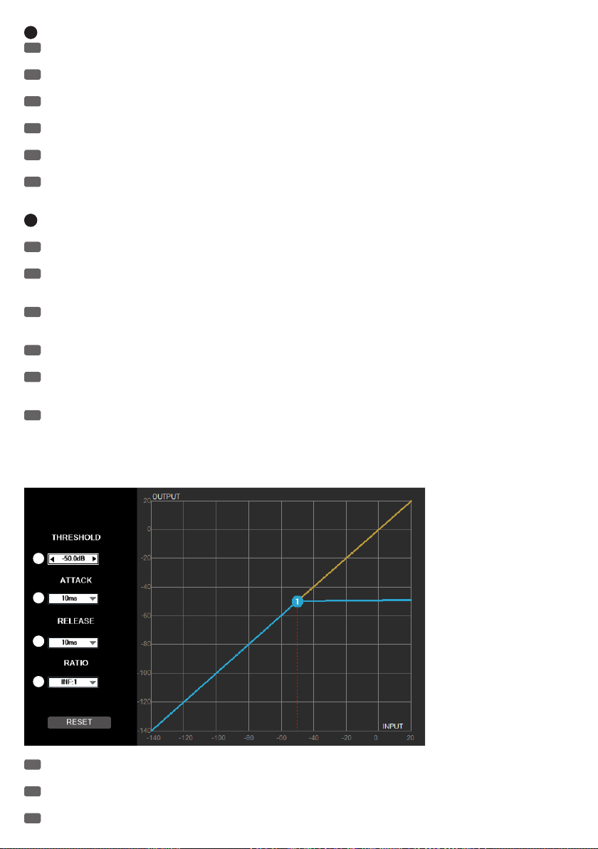
6
Q-FACTOR
EN
The value of the Q factor of the respective filter (filter quality) can be entered directly into the corresponding input field, or by using the arrow
buttons to the right of the input field (Q-factor 0.3 to 20).
DE
Der Wert des Q-Faktors des jeweiligen Filters (Filtergüte) kann mittels der direkten Eingabe in das entsprechende Eingabefeld, oder mit Hilfe
der Pfeiltasten rechts neben dem Eingabefeld erfolgen (Q-Faktor 0,3 bis 20).
FR
Pour régler la valeur du facteur Q (largeur de bande) de chaque bande de correction, vous pouvez taper directement la valeur dans le champ,
ou les touches flèche haut/bas à côté du champ Q (valeurs possibles : de 0,3 à 20).
ES
El valor del factorQ de cada filtro puede teclearse directamente, o seleccionarse con los botones de flecha situados a la derecha del valor del
factorQ (entre 0,3 y 20)
PL
Wartość opcji Q-Faktor danego filtra (jakości filtra) można zmieniać przez bezpośrednie wprowadzenie wartości w odpowiednim polu
wprowadzania lub użycie przycisków-strzałek znajdujących się na prawo obok pola wprowadzania (wartości opcji Q-Faktor wynoszą od 0,3 do 20).
IT
Il valore del fattoreQ del relativo filtro può essere digitato direttamente nel campo relativo o definito con i tasti freccia a destra del campo
(fattoreQ da 0,3 a 20).
7
GRAPHICAL EQUALIZER DISPLAY / GRAFISCHE EQUALIZER-DARSTELLUNG / REPRÉSENTATION GRAPHIQUE DE LA COURBE
D'ÉGALISATION / GRAFICZNE ODWZOROWANIE KOREKTORA DŹWIĘKU / EQUALIZZATORE GRAFICO
EN
The graphical representation of the EQ curve is used for quick and clear overview of the equalizer settings. Frequency and Gain can be changed
at the same time using the 5 points in the graphic representation of the frequency curve (click, hold and drag). Each dot represents a frequency
DE
Die grafische Darstellung der Equalizer-Kurve dient der schnellen und klaren Übersicht der Equalizer-Einstellungen. Frequenz und Verstärkung
können gleichzeitig mit Hilfe der 15 Punkte in der Frequenzkurve verändert werden (Klicken, Halten und Ziehen). Jeder Punkt steht für ein
Frequenzband.
FR
La représentation graphique de la courbe d'égalisation permet de visualiser rapidement et clairement les paramètres de l'égaliseur. Vous
pouvez agir directement sur la fréquence et le gain en même temps, en faisant glisser à la souris un des 5 points de la courbe graphique
d'égalisation. Chacun des points correspond à une bande de fréquences.
ES
La curva del ecualizador gráfico es útil para tener una visión clara y rápida de la ecualización. En el ecualizador gráfico pueden cambiarse a la
vez la frecuencia y la ganancia. Para ello, haga clic en uno de los 15puntos, y arrástrelo. Cada punto representa una banda de frecuencias.
PL
Graficzne odwzorowanie krzywej korektora dźwięku daje szybki i jasny przegląd ustawień korektora dźwięku. Częstotliwość i wzmocnienie
można zmieniać jednocześnie za pomocą piętnastu punktów znajdujących się na krzywej częstotliwości (kliknąć, przytrzymać i przeciągnąć). Każdy z
punktów odpowiada jednemu pasmu częstotliwości.
IT
La curva dell'equalizzatore grafico offre una rappresentazione chiara e rapida delle impostazioni dell'equalizzatore. È possibile modificare
contemporaneamente la frequenza e l'amplificazione utilizzando i 15punti della curva di frequenza (fare clic, tenere premuto e trascinare). A ogni
punto corrisponde una banda di frequenza.
MASTER LIMITER 1 & 2
1
2
343
EN
The limiter (peak limiter) is used to limit peaks in the audio signal of the line outputs. For this purpose, the following parameter settings are
available.
DE
Der Limiter (Spitzenwert-Begrenzer) dient dazu, Pegelspitzen im Audio-Signal der Line-Ausgänge zu begrenzen. Hierfür sind Einstellungen der
folgenden Parameter verfügbar.
FR
Le limiteur sert à atténuer les crêtes du signal audio de la sortie ligne. Voici les paramètres de réglage disponibles :
42
Page 43

ES
El limitador sirve para limitar los picos de la señal de las salidas de línea. Para ello, puede cambiar los siguientes parámetros.
PL
Limiter (ogranicznik wartości szczytowej) służy do ograniczania poziomów szczytowych sygnału audio wyjść liniowych. Dla tej opcji dostępne
są ustawienia następujących parametrów.
IT
Il limitatore consente di limitare i picchi di livello del segnale audio delle uscite di linea utilizzando le impostazioni dei seguenti parametri.
1
THRESHOLD
EN
Setting the threshold value from -80 dB to 19.9 dB, and to OFF (off). Use the arrow buttons in the threshold field to enter the desired value, or
use the point in the graph using the mouse (click, hold and drag).
DE
Einstellung des Schwellenwerts von -80dB bis 19,9dB und OFF (aus). Verwenden Sie für die Eingabe des gewünschten Werts die Pfeiltasten im
Threshold-Feld, oder benutzen dafür den Punkt in der grafischen Darstellung mit Hilfe der Computermaus (Klicken, Halten und Ziehen).
FR
Réglage de la valeur de seuil, de -80 dB à +19,9 dB et OFF (désactivé). Pour régler la valeur de Threshold désirée, vous pouvez taper
directement la valeur dans le champ, ou agir directement avec la souris sur le point de la représentation graphique (maintenez enfoncé le bouton de
la souris, puis faites glisser)
ES
Ajuste del nivel umbral de -80dB a 19,9dB y OFF (desactivado). Puede introducirse el valor con los botones de flecha o bien seleccionando y
arrastrando el punto de la gráfica con el ratón.
PL
Ustawienie wartości progowej w zakresie od –80 dB do 19,9 dB lub „OFF” (wyłączone). W celu wprowadzenia żądanej wartości należy użyć
przycisków-strzałek w polu progu lub punktu znajdującego się na graficznym odwzorowaniu i myszy komputera (kliknąć, przytrzymać i przeciągnąć).
IT
Impostazione del valore soglia da -80dB a 19,9dB e OFF (disattivato). Per inserire il valore desiderato è possibile utilizzare i tasti freccia o il
punto raffigurato nel grafico, trascinandolo con il tasto del mouse.
2
ATTACK
EN
Set the Attack Time (response time) from 1 ms to 2 s. Place the mouse pointer on the attack field, then click with the left mouse button to
select the desired value and confirm by clicking again with the left mouse button.
DE
Einstellen der Attack-Zeit (Ansprechzeit) von 1ms bis 2s. Führen Sie den Mauszeiger auf das Attack-Feld, klicken mit der linken Maustaste,
wählen den gewünschten Wert aus und klicken abermals mit der linken Maustaste.
FR
Réglage du temps d'attaque (rapidité de réaction), de 1 ms à 2 s. Cliquez sur le champ Attack, choisissez la valeur désirée puis cliquez de
nouveau.
ES
Ajuste del tiempo de ataque de 1ms a 2s. Sitúe el ratón en el campo «ATTACK», haga clic, seleccione un valor y haga clic de nuevo.
PL
Ustawienie czasu ataku w zakresie od 1 ms do 2 s. Przesunąć kursor myszy na pole czasu ataku, kliknąć lewym przyciskiem myszy, wybrać
żądaną wartość i ponownie kliknąć lewym przyciskiem myszy.
IT
Impostazione del tempo di attacco da 1ms a 2s. Spostare il cursore sul campo ATTACK, fare clic per selezionare il valore desiderato e fare clic
di nuovo.
3
RELEASE
EN
Set the Release Time (release time) from 10 ms to 2 s. Place the mouse pointer on the Release field, then click with the left mouse button to
select the desired value and confirm by clicking again with the left mouse button.
DE
Einstellen der Release-Zeit (Abfallzeit) von 10ms bis 2s. Führen Sie den Mauszeiger auf das Release-Feld, klicken mit der linken Maustaste,
wählen den gewünschten Wert aus und klicken abermals mit der linken Maustaste.
FR
Réglage de la durée de Release (retombée), de 10 ms à 2 s. Cliquez sur le champ Release, choisissez la valeur désirée puis cliquez de
nouveau.
ES
Ajuste del tiempo de decaimiento de 10ms a 2s. Sitúe el ratón en el campo «RELEASE», haga clic, seleccione un valor y haga clic de nuevo.
PL
Ustawienie czasu powrotu w zakresie od 10 ms do 2 s. Przesunąć kursor myszy na pole czasu powrotu, kliknąć lewym przyciskiem myszy,
wybrać żądaną wartość i ponownie kliknąć lewym przyciskiem myszy.
IT
Impostazione del tempo di rilascio da 10ms a 2s. Spostare il cursore sul campo RELEASE, fare clic per selezionare il valore desiderato e fare
clic di nuovo.
4
RATIO
EN
To adjust the ratio (ratio), place the mouse pointer on the Ratio field, then click with the left mouse button to select the desired value and
confirm by clicking again with the left mouse button. The usual value for a limiter function is INF:1.
DE
Zum Einstellen der Ratio (Regelverhältnis) führen Sie den Mauszeiger auf das Ratio-Feld, klicken mit der linken Maustaste, wählen den
gewünschten Wert aus und klicken abermals mit der linken Maustaste. Der übliche Wert für eine Limiter-Funktion ist INF:1.
FR
Pour régler la valeur de Ratio (taux de compression), cliquez sur le champ Ratio, choisissez la valeur désirée puis cliquez de nouveau. Dans le
cas d'une utilisation comme limiteur, la valeur de taux est de INF:1.
ES
Para cambiar la proporción (relación del limitador), sitúe el ratón en el campo «RATIO», haga clic, seleccione un valor y haga clic de nuevo. El
valor habitual del limitador es INF:1.
PL
W celu ustawienia proporcji należy przesunąć kursor myszy na pole proporcji, kliknąć lewym przyciskiem myszy, wybrać żądaną wartość i
ponownie kliknąć lewym przyciskiem myszy. Normalną wartością funkcji limitera jest INF:1 (∞:1).
IT
Per impostare la proporzione (rapporto del regolatore) spostare il cursore sul campo RATIO, fare clic per selezionare il valore desiderato, quindi
fare clic di nuovo. Il valore standard per una funzione limitatore è INF:1.
43
Page 44

AUDIO MATRIX / MATRICE AUDIO / MATRIZ DE AUDIO / FUNKCJA AUDIO MATRIX / MATRICE
AUDIO
EN
Each of the 8 input channels (INPUTS 1-8) can be individually routed to the two line outputs Master 1 and 2 using the audio matrix of the AM8
automatic mixer (M1 and M2). To select which input channel should be routed to which of the two line outputs, and which one should not, simply
click on the appropriate button. When a channel is routed to an output, the corresponding button is highlighted in blue (CHANNEL OPEN), otherwise, it
will be greyed out (CHANNEL CLOSED).
DE
Jeder der 8 Eingangs-Kanäle (INPUTS 1 - 8) kann mit Hilfe der Audio Matrix des AM8 Automatik-Mixers individuell auf die beiden Line-Ausgänge
Master 1 und 2 geroutet werden (M1 und M2). Die Auswahl, welcher Eingangs-Kanal auf welchen der beiden Line-Ausgänge geroutet wird und
welcher nicht, erfolgt durch einfaches Klicken auf die entsprechende Schaltfläche. Ist ein Kanal auf einen Ausgang geroutet, erscheint die
entsprechende Schaltfläche blau hervorgehoben (CHANNEL OPEN), ist er es nicht, grau hinterlegt (CHANNEL CLOSED).
FR
La matrice audio intégrée du mixeur automatique AM8 permet d'assigner individuellement les 8 canaux d'entrée (INPUTS 1 - 8) aux sorties
Master 1 et Master 2 (M1 et M2). Pour sélectionner la ou les sorties auxquelles assigner chaque canal d'entrée, il suffit de cliquer sur le bouton
correspondant. Dès qu'un canal est assigné à une sortie, le bouton passe en bleu (CHANNEL OPEN) ; s'il ne l'est pas, le bouton est gris (CHANNEL
CLOSED).
ES
Con la matriz de audio del mezclador automático AM8 puede enviarse cada uno de los 8canales de entrada (INPUTS 1 - 8) a las salidas de
línea Master1 y 2 (M1 y M2). Para seleccionar qué canal de entrada se envía a qué salida, simplemente haga clic en los botones. Si se está
enviando un canal a una determinada salida, el botón correspondiente aparecerá con fondo de color azul (CHANNEL OPEN); si no se envía, aparecerá
de color gris (CHANNEL CLOSED).
PL
Za pomocą funkcji Audio Matrix automatycznego miksera AM8 każdy z 8 kanałów wejściowych (INPUTS 1–8) może zostać z osobna
przetrasowany zarówno na wyjście liniowe Master 1, jaki i Master 2 (M1 i M2). Aby zdecydować, który kanał wejściowy ma/nie ma zostać
przetrasowany na jedno z dwóch wyjść liniowych, wystarczy kliknąć odpowiedni przycisk. Gdy dany kanał jest przetrasowywany na wyjście,
odpowiedni przycisk zostaje wyróżniony kolorem niebieskim (CHANNEL OPEN – KANAŁ OTWARTY) lub szarym w przypadku gdy funkcja ta jest
nieaktywna (CHANNEL CLOSED – KANAŁ ZAMKNIĘTY).
IT
Con la matrice audio del mixer automatico AM8, ciascuno degli 8canali di ingresso (INPUTS1 - 8) può essere instradato nelle due uscite di
linea Master1 e 2 (M1 e M2). Per selezionare quale canale di ingresso debba essere instradato in quale uscita di linea, basta un semplice clic sul
pulsante corrispondente. Se il canale è instradato in un'uscita, il pulsante corrispondete è di colore azzurro (CHANNEL OPEN), altrimenti è grigio
(CHANNEL CLOSED).
44
Page 45

SYSTEM SETTINGS / SYSTEMEINSTELLUNGEN / PARAMÈTRES SYSTÈME / CONFIGURACIÓN DEL
SISTEMA / USTAWIENIA SYSTEMU / IMPOSTAZIONI DI SISTEMA
1
2
3
4
1
THRESHOLD
EN
When the signal levels of input channels drop below a certain threshold, these will be muted by this feature. This means that for the
5
6
7
transmission of a channel, background noise, feedback and unwanted comb-filter effects from other active channels are effectively suppressed and
the speech intelligibility is thus enhanced. When the levels of input channels rise above a certain threshold, these will be automatically activated.
Setting the threshold value (Threshold) with the virtual fader is disabled during the automatic operation (the "AUTO" button is highlighted in yellow).
The threshold value is automatically adapted to the volume of ambient sounds. The manual setting of the threshold (-50 dB to +10 dB) for the
automatic activation of the input channels is achieved using the virtual fader. Click on "MAN" (the "MAN" button is highlighted in yellow). Adjust the
threshold so that ambient noise does not automatically activate an input channel, but that the activation of a channel by a speaker etc...remains
possible. Set the Hold Time of the selected channel using the virtual fader "HOLD TIME" as desired (0 - 2000 ms). The channel remains as is for the
duration of the set hold time, even after muting the audio signal. Another channel can therefore only be activated after the hold time expires.
DE
Eingangs-Kanäle, deren Signal-Pegel unter einem bestimmten Schwellenwert (Threshold) liegen, werden mit Hilfe dieser Funktion stumm
geschaltet. Somit werden bei der Übertragung eines Kanals Nebengeräusche, Rückkopplungen und unerwünschte Kammfiltereffekte durch weitere
offene Kanäle wirkungsvoll unterdrückt und die Sprachverständlichkeit gesteigert. Eingangs-Kanäle, deren Signal-Pegel über einem bestimmten
Schwellenwert liegen, werden automatisch aktiviert. Die Einstellung des Schwellenwerts (Threshold) durch den virtuellen Fader ist während des
automatischen Betriebs deaktiviert (Schaltfläche "AUTO" gelb hervorgehoben). Der Schwellenwert wird automatisch an die Lautstärke der
Umgebungsgeräusche angepasst. Die manuelle Einstellung des Schwellenwerts (-50 dB bis +10 dB) für die automatische Aktivierung der
Eingangskanäle erfolgt mit Hilfe des virtuellen Faders. Klicken Sie hierzu auf "MAN" (Schaltfläche "MAN" gelb hervorgehoben). Stellen Sie den
Schwellenwert so ein, dass Umgebungsgeräusche einen Eingangskanal nicht automatisch aktivieren, aber die Aktivierung eines Kanals durch einen
Sprecher etc. ermöglicht wird. Stellen Sie die Haltezeit des aktivierten Kanals mit Hilfe des virtuellen Faders "HOLD TIME" nach Wunsch ein (0 2000ms). Der Kanal bleibt so für die Dauer der eingestellten Haltezeit auch nach Verstummen des Audio-Signals aktiviert. Ein anderer Kanal kann
also erst nach Ablauf der Haltezeit aktiviert werden.
FR
Cette fonction permet de couper (Mute) automatiquement les canaux d'entrée dont le signal passe sous une valeur de seuil (Threshold)
déterminée. On évite ainsi l'accumulation de bruits ambiants, d'éventuels parasites et l'apparition d'effets de filtre en peigne : autant de phénomènes
inévitables dès que plusieurs micros sont ouverts simultanément, et qui nuisent à l'intelligibilité de la voix. Les canaux d'entrée sur lesquels le niveau
du signal est supérieur à la valeur de seuil sont, quant à eux, automatiquement activés. En mode de fonctionnement automatique, le fader virtuel de
réglage de la valeur de seuil est automatiquement désactivé (bouton "AUTO" en jaune). La valeur de seuil est s'adapte automatiquement en fonction
du niveau de bruit ambiant. Le réglage manuel de la valeur de seuil (de -50 dB à +10 dB) de fermeture/ouverture automatique des canaux d'entrée
s'effectue par l'intermédiaire du fader virtuel. Cliquez sur "MAN" (le bouton "MAN" passe en vert). Réglez la valeur de seuil de façon à ce que le
canal d'entrée reste fermé sur le bruit de fond, mais s'ouvre dès apparition du signal "utile" (parole, etc.). Réglez comme désiré la durée de maintien
d'ouverture après activation sur le canal avec le fader virtuel "HOLD TIME" (de 0 à 2000 ms). En mix automatique, le canal reste activé pour la durée
ainsi réglée, même si le signal audio disparaît. L'activation d'un autre canal ne peut intervenir qu'à l'issue de cette durée de Hold.
ES
Esta función silenciará los canales de entrada con un nivel de señal inferior a un determinado umbral (Threshold). De esta forma se evitará con
eficacia el ruido de fondo de canal, la realimentación acústica y los molestos efectos de filtro de peine que se producen al tener muchos canales
abiertos, y se conseguirá una mayor inteligibilidad de la voz. Los canales de entrada con un nivel de señal superior a dicho umbral se activarán
automáticamente. En modo automático, no se podrá ajustar el umbral (Threshold) mediante el fader (botón «AUTO» en color amarillo). El nivel umbral
se ajusta automáticamente según el volumen del ruido de fondo. En modo manual, el nivel umbral (−50dB a +10dB) se ajusta con el fader para que
los canales de entrada se activen automáticamente. Haga clic en «MAN» (botón «MAN» cambia a color amarillo). Ajuste el umbral de modo que el
ruido de fondo no active automáticamente un canal de entrada, sino que se active al hablar un orador, etc. Ajuste el tiempo de mantenimiento del
canal activado mediante el fader «HOLD TIME», de 0 a 2000ms). Cuando la señal de audio cae por debajo del umbral, el canal permanece activado
durante el tiempo de mantenimiento configurado. Solo se activa otro canal después del tiempo de mantenimiento.
45
Page 46

PL
Dzięki tej funkcji kanały wejściowe o poziomach sygnałów znajdujących się poniżej określonej wartości progowej (Threshold) zostaną włączone
bezgłośnie (bez trzasków). Dzięki temu podczas przekazu na danym kanale dodatkowe odgłosy, sprzężenia zwrotne oraz niechciane efekty działania
filtra grzebieniowego pochodzące z pozostałych otwartych kanałów zostaną skutecznie stłumione, a wyrazistość (stopień zrozumiałości) mowy
ulegnie zwiększeniu. Kanały wejściowe o poziomach sygnałów znajdujących się poniżej określonej wartości progowej zostaną automatycznie
aktywowane. Ustawianie wartości progowej (Threshold) za pomocą wirtualnego tłumika nastawnego nie jest możliwe podczas pracy w trybie
automatycznym (przycisk „AUTO” wyróżniony kolorem żółtym). Wartość progowa jest automatycznie dostosowywana do głośności hałasu otoczenia.
Ręczne ustawienie wartości progowej (od –50 dB do +10 dB) automatycznej aktywacji kanałów wejściowych następuje z wykorzystaniem
wirtualnego tłumika nastawnego. W tym celu należy kliknąć przycisk „MAN”, który zostanie wyróżniony kolorem żółtym. Poziom wartości progowej
należy ustawić tak, aby hałas otoczenia nie włączył automatycznie kanału wejściowego, przy czym włączenie danego kanału przez użytkownika
urządzenia musi być nadal możliwe. Za pomocą wirtualnego tłumika nastawnego ustawić według własnego upodobania czas wstrzymania („HOLD
TIME”) aktywnego kanału (0–2000 ms). Kanał pozostanie aktywny przez ustawiony czas wstrzymania, nawet po wyciszeniu sygnału audio. Tak więc
inny kanał może zostać aktywowany dopiero po upływie czasu wstrzymania.
IT
I canali di ingresso con livelli di segnale al di sotto di un determinato valore soglia (Threshold) vengono silenziati con questa funzione. In questo
modo, durante la trasmissione di un canale si evitano i rumori di fondo, i ritorni e gli indesiderati effetti di filtro a pettine che si producono quando ci
sono molti canali aperti; anche l'intelligibilità della voce migliora. I canali di ingresso con livelli di segnale al di sopra di un determinato valore soglia
si attivano automaticamente. In modalità automatica, non è possibile impostare il valore soglia (Threshold) con il fader virtuale (pulsante "AUTO"
gialle). Il valore soglia viene impostato automaticamente sul volume del rumore di fondo. L'impostazione manuale del valore soglia (da -50dB a
+10dB) per l'attivazione automatica dei canali d'ingresso si esegue con il fader virtuale. Fare clic su "MAN" (pulsante "MAN" giallo). Impostare il
valore soglia in modo che un canale d'ingresso non sia attivato dal rumore di fondo ma ad esempio da un oratore. Impostare a piacere il tempo di
sospensione del canale attivato utilizzando il fader virtuale "HOLD TIME" (0 - 2.000ms). In questo modo il canale resta attivo per tutto il tempo di
sospensione impostato, anche dopo il silenziamento del segnale audio. È possibile quindi attivare un altro canale solo una volta trascorso il tempo di
sospensione.
2
MAX. OPEN CH
EN
To set the maximum number of simultaneously active input channels on the drop-down menu, select the desired number and click "OK". In the
opening window, click again on "OK".
DE
Stellen Sie die maximale Anzahl der gleichzeitig aktivierbaren Eingangs-Kanäle ein, indem Sie auf das Ziffern-Aufklappmenü klicken, die
gewünschte Anzahl auswählen und auf "OK" klicken. Im nun geöffneten Fenster klicken Sie wiederum auf "OK".
FR
Pour définir le nombre maximal de canaux d'entrée pouvant être activés simultanément, choisissez-le dans le menu local, puis cliquez sur
"OK". Dans la fenêtre alors ouverte, cliquez de nouveau sur "OK".
ES
Establezca el máximo número de canales de entrada activados simultáneamente. Para ello, haga clic en la lista de números, seleccione uno de
ellos y haga clic en «OK». En la ventana que se abre, haga clic en «OK».
PL
Ustawić maksymalną liczbę jednocześnie aktywowalnych kanałów wejściowych, klikając rozwijane menu zawierające cyfry, a następnie
wybrać żądaną wartość i kliknąć „OK”. Kliknąć ponownie „OK” w oknie, które właśnie się otworzyło.
IT
Per impostare il numero massimo di canali d'ingresso attivabili contemporaneamente, fare clic sul menu dei numeri, selezionare il numero
desiderato e fare clic su "OK". Fare clic di nuovo su "OK" nella finestra che si apre.
3
DEVICE IP
EN
The IP address of the device is factory set to 192.168.1.88. To change the IP address (e.g., for daisy-chaining multiple AM8 automatic mixer),
click on the address field, change the number of the last digit (e.g. 192.168.1.89) and click "OK". In the opening window, click again on "OK". Restart
the software and reconnect the device to the software.
DE
Die IP-Adresse des Geräts ist ab Werk auf 192.168.1.88 eingestellt. Zum Ändern der IP-Adresse (z.B. Kaskadierung mehrerer AM8
Automatik-Mixer) klicken Sie auf das Adress-Feld, ändern die Zahl der letzten Stelle (z.B. 192.168.1.89) und klicken auf "OK". Im nun geöffneten
Fenster klicken Sie wiederum auf "OK". Starten Sie die Software neu und verbinden das Gerät erneut mit der Software.
FR
L'adresse IP de l'appareil est réglée en usine sur 192.168.1.88. Pour modifier cette adresse IP (par exemple, afin de cascader plusieurs
mixeurs automatiques AM8), cliquez sur le champ DEVICE IP,modifiez le dernier nombre (par exemple, 192.168.1.89) puis cliquez sur "OK". Dans la
fenêtre alors ouverte, cliquez de nouveau sur "OK". Relancez le logiciel, et rétablissez la liaison de l'appareil avec le logiciel.
ES
La dirección IP por defecto del equipo es 192.168.1.88. Para cambiar la dirección IP (por ejemplo, al conectar en cascada varios mezcladores
automáticos AM8), haga clic en en el campo de la dirección IP, cambie la última cifra (192.168.1.89, por ejemplo) y haga clic en «OK». En la ventana
que se abre, haga clic en «OK». Reinicie el programa de software y vuelva a conectar el equipo al software.
PL
Fabrycznie ustawionym adresem IP urządzenia jest adres 192.168.1.88. W celu zmiany adresu IP (np. dla kaskadowania kilku automatycznych
mikserów AM) należy kliknąć pole adresu, zmienić wartość po ostatniej kropce (np. 192.168.1.89) i kliknąć „OK”. Kliknąć ponownie „OK” w oknie,
które właśnie się otworzyło. Ponownie uruchomić oprogramowanie i na nowo połączyć je z urządzeniem.
IT
L'indirizzo IP dell'apparecchio è preimpostato su 192.168.1.88. Per modificare l'indirizzo IP (ad esempio con il collegamento a cascata di
diversi mixer automatici AM8) fare clic sul campo indirizzo, modificare l'ultima cifra (ad esempio 192.168.1.89) e fare clic su "OK". Fare clic di nuovo
su "OK" nella finestra che si apre. Riavviare il software e collegare di nuovo l'apparecchio con il software.
4
USERNAME AND PASSWORD / BENUTZER UND PASSWORT / NOM D'UTILISATEUR ET MOT DE PASSE / USUARIO Y CONTRASEÑA /
UŻYTKOWNIK I HASŁO / UTENTE E PASSWORD
EN
For managing and editing the software, 2 users with different password-protected access rights can be set up ("admin" and "user"). The user
"admin" has access to all menu items in the software, the user "user" to all menu items except "MATRIX" and "SYSTEM". The factory preset
46
Page 47

password for both users (USER PSW) is "000000" (six times the number zero). The password of the user who is currently logged on to the AM8
automatic mixer can be changed in the following ways: Click in the field for the old password "OLD PSW" and enter the old password. Now enter the
new password (maximum 6 characters) in the "NEW PSW" field and again in the field "CONFIRM PSW" and confirm by clicking on the "CHANGE
USER" button. In the opening window, click "OK", reconnect the device to the software (MENU-> CONNECT) and log on using the new user
password.
DE
Für die Verwaltung und Editierung der Software können 2 Benutzer mit unterschiedlichen Zugriffsrechten passwortgeschützt angemeldet
werden ("admin" und "user"). Der Benutzer "admin" hat Zugriffsrechte auf alle Menüpunkte der Software, der Benutzer "user" auf alle Menüpunkte
außer auf "MATRIX" und "SYSTEM". Das Benutzerpasswort (USER PSW) ab Werk ist für beide Benutzernamen "000000" (sechs mal die Zahl Null).
Das Benutzerpasswort des Benutzers, welcher aktuell im AM8 Automatik-Mixer angemeldet ist, kann auf folgende Weise geändert werden: Klicken
Sie in das Feld für das alte Passwort "OLD PSW" und geben das alte Passwort ein. Geben Sie nun das neue Passwort (maximal 6 Zeichen) in das
Feld "NEW PSW" und erneut in das Feld "CONFIRM PSW" ein und bestätigen diesen Vorgang durch Klicken auf die Schaltfläche "CHANGE USER".
Klicken Sie im nun geöffneten Fenster auf "OK", verbinden das Gerät erneut mit der Software (MENU -> CONNECT) und melden sich mit dem neuen
Benutzerpasswort an.
FR
Pour l'administration et le paramétrage du logiciel, deux niveaux d'accès utilisateur sont prévus : "admin" et "user". L'utilisateur "admin" peut
accéder à tous les éléments de menu du logiciel, tandis que l'utilisateur "user" se voit refuser l'accès à "MATRIX" et "SYSTEM". À la sortie d'usine,
les deux mots de passe (USER PSW) sont réglés sur "000000" (six fois le chiffre zéro). Pour modifier le mot de passe utilisateur actuellement
paramétré dans le mixeur automatique AM8, procédez comme suit : Cliquez dans le champ correspondant à l'ancien mot de passe, "OLD PSW", et
entrez l'ancien mot de passe. Entrez ensuite le nouveau mot de passe (6 caractères maxi) dans le champ "NEW PSW", et entrez-le de nouveau dans
le champ "CONFIRM PSW" ; enfin, validez les entrées en cliquant sur le bouton "CHANGE USER". Cliquez sur "OK" dans la fenêtre actuellement
ouverte, établissez de nouveau la liaison avec l'appareil (MENU -> CONNECT) puis entrez votre nouveau mot de passe utilisateur.
ES
Para la gestión y edición, el software tiene 2cuentas de usuario protegidas por contraseña con derechos diferentes de acceso («admin» y
«user»). El usuario «admin» tiene derechos de acceso a todo el software, mientras que el usuario «user» no puede entrar en «MATRIX» ni en
«SYSTEM». Por defecto, la contraseña (USER PSW) para ambos usuarios es «000000» (seis ceros seguidos). Se pueden cambiar las contraseñas de
usuario memorizadas en el mezclador automático AM8 de la siguiente manera: Haga clic en el campo «OLD PSW» y escriba la contraseña. A
continuación, escriba la nueva contraseña (6dígitos como máximo) en el campo «NEW PSW», repítala en «CONFIRM PSW» y confirme pulsando el
botón «CHANGE USER». En la ventana que se abre, haga clic en «OK», conéctese de nuevo al equipo con el software (MENU -> CONNECT) e inicie
sesión con la nueva contraseña de usuario.
PL
Zarządzanie i edytowanie z wykorzystaniem oprogramowania jest możliwe dla dwóch użytkowników posiadających różne uprawnienia
dostępowe chronione hasłem i wymagające zalogowania, tj. „admin” i „user”. Użytkownik „admin” (administrator) ma uprawnienia dostępowe do
wszystkich opcji menu programu, a użytkownik „user” (zwykły użytkownik) posiada dostęp do tych samych opcji, za wyjątkiem pozycji „MATRIX” i
„SYSTEM”. Fabrycznie ustawionym hasłem (USER PSW – HASŁO UŻYTKOWNIKA) dla obu użytkowników jest hasło „000000” (sześć cyfr zero). Hasło
użytkownika, który jest aktualnie zalogowany do oprogramowania automatycznego miksera AM8, może zostać zmienione w następujące sposoby:
Kliknąć w polu starego hasła „OLD PSW” (STARE HASŁO) i wprowadzić stare hasło. W polu „NEW PSW” (NOWE HASŁO) należy teraz wprowadzić
nowe hasło (maksymalnie 6 znaków) i ponownie to samo hasło w polu „CONFIRM PSW” (POTWIERDŹ HASŁO), a następnie potwierdzić operację,
klikając przycisk „CHANGE USER” (ZMIEŃ UŻYTKOWNIKA). W oknie, które właśnie się otworzyło, należy kliknąć „OK”, na nowo połączyć urządzenie z
oprogramowaniem (MENU -> CONNECT), a następnie zalogować się, wykorzystując nowe hasło użytkownika.
IT
Per la gestione e la modifica, il software dispone di due account utente con diritti di accesso diversi e protetti da password ("admin" e "user").
L'utente "admin" ha diritti di accesso a tutte le voci di menu del software, l'utente "user" a tutte le voci tranne "MATRIX" e "SYSTEM". La password
utente (USER PSW) preimpostata è "000000" (sei zeri) per entrambi i nomi utente. Per modificare la password dell'utente attualmente registrato in
AM8, procedere nel seguente modo: Fare clic sul campo della password precedente "OLD PSW" e inserire la password in uso. Nel campo "NEW
PSW" inserire invece la nuova password (max 6caratteri) e ripeterla nel campo "CONFIRM PSW", quindi confermare l'operazione facendo clic sul
pulsante "CHANGE USER". Ora fare clic su "OK" nella finestra aperta, collegare di nuovo l'apparecchio al software (MENU -> CONNECT) e accedere
con la nuova password utente.
5
PANEL LOCK
EN
In order to protect the device against accidental operation, the controls of the AM8 automatic mixer can be locked. Click the "ON" button with
the left mouse button (the "ON" button will be highlighted yellow). To release the controls, click the "OFF" button.
DE
Um das Gerät vor unbeabsichtigter Bedienung zu schützen, können die Bedienelemente des AM8 Automatik-Mixers gesperrt und damit außer
Funktion gesetzt werden. Klicken Sie dafür mit der linken Maustaste auf die Schaltfläche "ON" (die Schaltfläche "ON" wird nun gelb hervorgehoben).
Um die Bedienelemente wieder freizugeben, klicken Sie auf die Schaltfläche "OFF".
FR
Pour protéger le mixeur automatique AM8 contre toute utilisation non autorisée, vous pouvez verrouiller ses commandes"physiques". Pour ce
faire, cliquez sur le champ "ON" (qui passe alors en jaune). Pour rétablir l'accès aux commandes physiques, cliquez sur le champ "OFF".
ES
Para evitar operar el mezclador automático AM8 de forma involuntaria, es posible bloquear y desactivar los controles. Haga clic en el botón
«ON» (el fondo cambiará a amarillo). Para desbloquear los controles, haga clic en el botón «OFF».
PL
Aby uniemożliwić przypadkowe aktywowanie funkcji urządzenia, elementy obsługi automatycznego miksera AM8 można zablokować,
wyłączając ich działanie. W tym celu kliknąć lewym przyciskiem myszy przycisk „ON”, który zostanie wyróżniony kolorem żółtym. W celu ponownego
odblokowania elementów obsługi należy kliknąć przycisk „OFF”.
IT
Per proteggere l'apparecchio da uso incidentale, è possibile bloccare e pertanto disattivare i controlli del mixer automatico AM8. Per procedere,
fare clic sul pulsante "ON" (che diventa giallo); per sbloccare di nuovo i controlli, fare clic sul pulsante "OFF".
47
Page 48

6
DEVICE MODE
EN
When using a single AM8 automatic mixer, it must be configured as a master unit. When daisy-chaining up to 16 AM8 automatic mixers using
the LINK IN / LINK OUT interface on the rear panel of the device (see point 14 CONNECTIONS, CONTROLS, AND INDICATORS), the device serving as
the master unit needs to be configured as the master unit. Click the "MAST" button with the left mouse button (the "MAST" button will be highlighted
yellow). All other AM8 automatic mixers in the audio system will be configured as slave units. Click the "SLAVE" button with the left mouse button
(the "SLAVE" button will be highlighted yellow).
DE
Beim Einsatz eines einzelnen AM8 Automatik-Mixers, muss dieser als Master-Einheit konfiguriert sein. Beim Kaskadieren von bis zu 16 AM8
Automatik-Mixern mit Hilfe der LINK IN / LINK OUT Schnittstelle auf der Rückseite des Geräts (siehe Punkt 14, ANSCHLÜSSE, BEDIEN- UND
ANZEIGEELEMENTE), muss das Gerät, welches als Master-Einheit dienen soll, als Master-Einheit konfiguriert sein. Klicken Sie hierzu mit der linken
Maustaste auf die Schaltfläche "MAST" (die Schaltfläche "MAST" wird nun gelb hervorgehoben). Alle weiteren AM8 Automatik-Mixer des
Audio-Systems werden als Slave-Einheit konfiguriert. Klicken Sie hierzu mit der linken Maustaste auf die Schaltfläche "SLAVE" (die Schaltfläche
"SLAVE" wird nun gelb hervorgehoben).
FR
Si vous utilisez votre mixeur automatique AM8 seul, il faut le configurer en mode Master. Si vous cascadez plusieurs mixeurs automatiques
AM8 (jusqu'à 16) via les connecteurs LINK IN / LINK OUT à l'arrière de l'appareil (voir point 14, CONNECTEURS, CONTRÔLES ET INDICATEURS), il faut
configurer un des appareils en mode Master. Pour ce faire, cliquez sur le bouton "MAST" (qui passe en jaune). Tous les autres mixeurs automatiques
AM8 de la configuration en cascade doivent alors se trouver en mode Slave. Pour ce faire, cliquez sur le bouton "SLAVE" (qui passe en jaune).
ES
Cuando se utiliza un único mezclador automático AM8, debe configurarse como equipo maestro. Cuando se conectan en cascada hasta
16mezcladores automáticos AM8 mediante el puerto LINK IN / LINK OUT del panel posterior (ver punto14 de la sección CONEXIONES, CONTROLES E
INDICADORES), debe configurar como master el equipo que va a funcionar como maestro. Para ello, haga clic en el botón «MAST» (el fondo cambiará
a amarillo). Hay que configurar el resto de mezcladores automáticos AM8 como esclavos. Haga clic en el botón «SLAVE» (el fondo cambiará a
amarillo).
PL
W przypadku korzystania z jednego automatycznego miksera AM8 musi on zostać skonfigurowany jako jednostka główna. W przypadku
kaskadowania maksymalnie 16 automatycznych mikserów AM8 za pomocą interfejsu LINK IN/LINK OUT znajdującego się na tylnym panelu
urządzenia (patrz punkt 14 „PRZYŁĄCZA, ELEMENTY OBSŁUGI I WSKAŹNIKI”) urządzenie mające pełnić funkcję urządzenia głównego musi zostać
skonfigurowane jako jednostka główna. W tym celu kliknąć lewym przyciskiem myszy przycisk „MAST” (TRYB URZĄDZENIA GŁÓWNEGO), który od
teraz będzie wyróżniony kolorem żółtym. Wszystkie pozostałe automatyczne miksery AM8 systemu audio zostaną skonfigurowane jako jednostki
podporządkowane. W tym celu kliknąć lewym przyciskiem myszy przycisk „SLAVE” (TRYB URZĄDZENIA PODPORZĄDKOWANEGO), który od teraz
będzie wyróżniony kolorem żółtym.
IT
Se si utilizza un solo mixer automatico AM8, deve essere configurato come unità master. Se si collegano a cascata fino a 16mixer automatici
AM8 tramite la porta LINK IN / LINK OUT che si trova sul lato posteriore dell'apparecchio (v.punto14, CONNESSIONI, COMANDI E INDICATORI),
l'apparecchio che deve fungere da master deve essere configurato come master. Per procedere, fare clic sul pulsante "MAST" (che diventa giallo).
Tutti gli altri mixer automatici AM8 del sistema audio vanno configurati come unità slave. Per procedere, fare clic sul pulsante "SLAVE" (che diventa
giallo).
7
FACTORY SETTINGS
EN
To reset all settings, such as equalizers and routing, to the default settings, click the "RESTORE" button with the left mouse button. To confirm
the operation, click "YES" in the pop-up window, to cancel click "NO".
DE
Um alle Einstellungen, wie z.B. Equalizer und Routing, auf die Grundeinstellung zurückzusetzen, klicken Sie mit der linken Maustaste auf die
Schaltfläche "RESTORE". Zum Bestätigen des Vorgangs klicken Sie auf "YES" im nun geöffneten Fenster, zum Abbrechen auf "NO".
FR
Pour réinitialiser tous les paramètres de l'appareil (égaliseurs, assignations...), cliquez sur le bouton "RESTORE". Pour confirmer, cliquez ensuite
sur "YES" dans la fenêtre qui s'est ouverte, ou sur "NO" si vous désirez annuler la réinitialisation.
ES
Para restablecer todos los ajustes (como la del ecualizador y la matriz de envíos) a la configuración de fábrica, haga clic en el botón
«RESTORE». Para confirmar, haga clic en «YES» en la ventana que se abre; para cancelar, haga clic en «NO».
PL
W celu przywrócenia wszystkich ustawień do wartości fabrycznych, np. ustawień korektora dźwięku i trasowania, należy kliknąć lewym
przyciskiem myszy przycisk „RESTORE” (PRZYWRÓĆ). Aby potwierdzić lub przerwać operację, należy odpowiednio kliknąć przycisk „YES” (TAK) lub
„NO” (NIE) w oknie, które właśnie się otworzyło.
IT
Per ripristinare tutte le impostazioni, quali Equalizer e Routing, riportandole ai valori iniziali, fare clic sul pulsante "RESTORE". Nella finestra che
si apre fare clic su "YES" per confermare l'operazione, su "NO" per interromperla.
48
Page 49

MENU / MENÜ / MENU / MENÚ / MENU / MENU
EN
OPEN FILE / SAVE FILE
Save and load user settings (SAVE FILE / OPEN FILE). Custom settings can be saved directly to the computer as data files and can be reloaded. These
data files contain all of the settings, such as equalizer, limiter, routing, channel groups etc..
DE
OPEN FILE / SAVE FILE
Sichern und Laden von Benutzer-Einstellungen (SAVE FILE / OPEN FILE). Benutzer-Einstellungen können als Daten-File direkt auf dem Rechner
gespeichert und wieder geladen werden. Diese Daten-Files enthalten alle Einstellungen, wie Equalizer, Limiter, Routing, Kanal-Gruppen etc..
FR
OPEN FILE / SAVE FILE
Ouverture/enregistrement de fichiers de paramètres utilisateur (SAVE FILE / OPEN FILE). Les valeurs de paramètres peuvent être exportées/importées
sous forme de fichier de données sur/depuis l'ordinateur. Ces fichiers incluent tous les réglages de l'AM8 : égaliseur, limiteur, assignation, groupes
de canaux, etc.
ES
OPEN FILE / SAVE FILE
Permite guardar y recuperar la configuración del usuario (SAVE FILE / OPEN FILE). La configuración del usuario se guarda en un archivo de datos
en el ordenador que posteriormente se puede recuperar. Este archivo de datos incluye toda la configuración, como la del ecualizador, el limitador, la
matriz de envíos, los grupos de canales, etc.
PL
OPEN FILE/SAVE FILE (OTWIERANIE/ZAPISYWANIE USTAWIEŃ UŻYTKOWNIKA)
Zapisywanie i otwieranie ustawień użytkownika (SAVE FILE/OPEN FILE). Ustawienia użytkownika można zapisywać bezpośrednio na komputerze w
formie plików danych i ponownie je wczytywać. Wspomniane pliki danych zawierają ustawienia funkcji takich jak korektor dźwięku, limiter, trasowa-
nie, grupy kanałów itd.
IT
OPEN FILE / SAVE FILE
Salvataggio e caricamento delle impostazioni utente (SAVE FILE / OPEN FILE). Le impostazioni utente possono essere salvate direttamente sul
computer e recuperate successivamente. Questi file di dati contengono tutte le impostazioni, relative ad esempio all'equalizzatore, al limitatore,
all'instradamento, ai gruppi di canali ecc.
EN
CONNECT / DISCONNECT
Connecting and disconnecting a connection between the AM8 automatic mixer and the computer (for information about this procedure, see "CONNECTING TO A WINDOWS PC").
DE
CONNECT / DISCONNECT
Herstellen und Trennen einer Verbindung des AM8 Automatik-Mixers zum Rechner (Vorgehensweise siehe "VERBINDUNG MIT EINEM WINDOWS PC
HERSTELLEN").
FR
CONNECT / DISCONNECT
Activation/désactivation de la connexion du mixeur automatique AM8 à l'ordinateur (pour la procédure, voir "CONFIGURATION DE LA LIAISON AVEC
UN PC SOUS WINDOWS").
ES
CONNECT / DISCONNECT
Permite conectar y desconectar un mezclador automático AM8 desde el ordenador (ver procedimiento en «CONEXIÓN A UN PC CON WINDOWS»).
PL
CONNECT/DISCONNECT (POŁĄCZ/ROZŁĄCZ)
Nawiązywanie i kończenie połączenia automatycznego miksera AM8 z komputerem (kroki, jakie należy wykonać w celu połączenia, opisano w
punkcie „NAWIĄZYWANIE POŁĄCZENIA Z KOMPUTEREM Z SYSTEMEM OPERACYJNYM WINDOWS”).
IT
CONNECT / DISCONNECT
Attivazione e disattivazione di un collegamento del mixer automatico AM8 al computer (per il modo di procedere v."COLLEGAMENTO A UN PC CON
SISTEMA OPERATIVO WINDOWS").
EN
GROUP
Managing the channel groups. To open the groups window, click on "MENU", then place the pointer on "GROUP" and click once with the left mouse
button.
DE
GROUP
Verwalten der Kanal-Gruppen. Zum Öffnen des Gruppen-Fensters klicken Sie auf "MENU", führen den Mauszeiger auf "GROUP" und klicken einmal
mit der linken Maustaste.
FR
GROUP
Gestion des groupes de canaux Pour ouvrir la fenêtre des groupes de canaux, cliquez sur "MENU", cliquez sur le bouton "GROUP".
ES
GROUP
Permite gestionar los grupos de canales. Para abrir la ventana de grupos, haga clic en «MENU», seleccione «GROUP» con el ratón y haga clic una vez.
49
Page 50
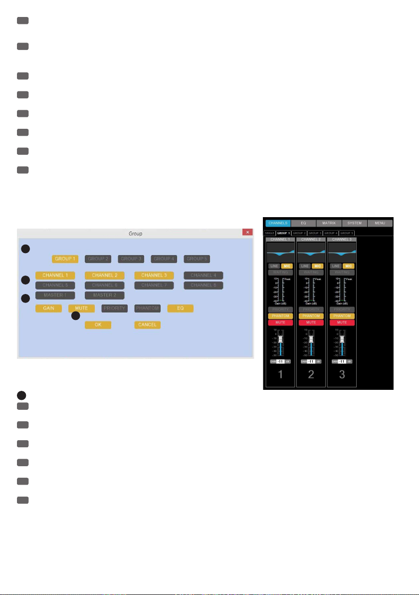
PL
GROUP (GRUPA)
Zarządzanie grupami kanałów. W celu otwarcia okna grup kanałów należy kliknąć „MENU”, przesunąć kursor myszy na „GROUP” i kliknąć jeden raz
lewym przyciskiem myszy.
IT
GROUP
Gestione dei gruppi di canali. Per aprire la finestra dei gruppi, fare clic su "MENU", spostare il cursore su "GROUP" e fare clic.
EN
EXIT(X)
Exit the AUTOMIX8 software. Previous settings are retained in the AM8 automatic mixer.
DE
EXIT(X)
Beenden der Software AUTOMIX8. Zuvor durchgeführte Einstellungen bleiben dem AM8 Automatik-Mixer erhalten.
FR
EXIT(X)
Pour quitter le logiciel AUTOMIX8. Les réglages de paramètres effectués précédemment sont enregistrés dans le mixeur automatique AM8.
ES
EXIT(X)
Cierra el programa AUTOMIX8. Los ajustes realizados se guardan en el mezclador automático AM8.
PL
EXIT(X) (WYJŚCIE (X))
Zamknięcie oprogramowania AUTOMIX8. Wcześniej wprowadzone zmiany ustawień automatycznego miksera AM8 pozostają zachowane.
IT
EXIT(X)
Chiusura del software AUTOMIX8. Le impostazioni effettuate permangono nel mixer automatico AM8.
CHANNEL GROUPS / KANAL-GRUPPEN / GROUPES DE CANAUX / GRUPOS DE CANALES / GRUPY
KANAŁÓW / GRUPPI DI CANALI
1
2
3
4
1
EN
To group input or output channels within a channel group, click on one of the 5 channel groups to edit (GROUP 1-5). The button of the
respective group is highlighted in yellow.
DE
Um Eingangs- bzw. Ausgangs-Kanäle in einer Kanal-Gruppe zusammenzufassen, klicken Sie auf eine der 5 Kanal-Gruppen, um sie zu
bearbeiten (GROUP 1 - 5). Die Schaltfläche der ausgewählten Gruppe wird nun gelb hervorgehoben.
FR
Pour rassembler plusieurs canaux d'entrée ou de sortie dans un même Groupe, cliquez sur le bouton d'un des cinq groupes de canaux (GROUP
1 - 5). Le bouton du canal choisi passe alors au jaune.
ES
Para asignar los canales de entrada y salida en un grupo de canales, haga clic en uno de los 5grupos de canales para editarlo (GROUP1 - 5).
El grupo activo estará de color amarillo.
PL
W celu przypisania kanałów wejściowych/wyjściowych do jednej grupy kanałów należy kliknąć jedną z pięciu grup kanałów, co umożliwi jej
edytowanie (GROUP 1–5 – GRUPY 1–5). Przycisk wybranej grupy zostanie wtedy wyróżniony kolorem żółtym.
IT
Per raggruppare i canali di ingresso e uscita in un gruppo di canali, fare clic su uno dei 5gruppi di canali per elaborarli (GROUP1 - 5). Il
pulsante del gruppo selezionato è giallo.
50
Page 51

2
EN
Click on the button of the channels (CHANNEL 1-8 / MASTER 1 + 2) to be grouped in this channel group.. The buttons of the selected channels
are highlighted in yellow. To remove a channel from a group, click on the button of the corresponding channel, the button will appear greyed out.
Input and output channels can not be grouped in a channel group.
DE
Klicken Sie auf die Schaltflächen der Kanäle (CHANNEL 1 - 8 / MASTER 1 + 2), die in dieser Kanal-Gruppe zusammengefasst werden sollen.
Die Schaltflächen der so ausgewählten Kanäle erscheinen nun gelb hervorgehoben. Um einen Kanal aus einer Gruppe herauszunehmen, klicken Sie
wiederum auf die Schaltfläche des entsprechenden Kanals, die Schaltfläche erscheint nun grau hinterlegt. Eingangs- und Ausgangs-Kanäle können
nicht gemeinsam in einer Kanal-Gruppe zusammengefasst werden.
FR
Cliquez ensuite sur les boutons des canaux (CHANNEL 1 - 8 / MASTER 1 + 2) que vous désirez intégrer au Groupe. Les boutons ainsi
sélectionnés passent alors au jaune. Pour enlever un canal d'un Groupe, cliquez de nouveau sur le bouton du canal correspondant : ce bouton
redevient alors gris. Il est impossible de mélanger canaux d'entrée et canaux de sortie dans un même Groupe de canaux.
ES
Haga clic en los botones de canal (CHANNEL1 - 8 / MASTER1 + 2) para asignarlos a este grupo de canales. El canal activo estará de color
amarillo. Para eliminar un canal del grupo, haga clic de nuevo en el botón de canal (el fondo del botón pasará a gris). En un mismo grupo de canales
no puede haber canales de entrada y de salida.
PL
Kliknąć przyciski kanałów (CHANNEL 1–8/MASTER 1 + 2 – KANAŁY 1–8/MASTER 1 + 2), które mają zostać przypisane do wybranej wcześniej
grupy kanałów. Przyciski wybranych w ten sposób kanałów zostaną wtedy wyróżnione kolorem żółtym. W celu usunięcia kanału z grupy należy
ponownie kliknąć przycisk odpowiedniego kanału, a ten zostanie wtedy wyróżniony kolorem szarym. Kanały wejściowe i wyjściowe nie mogą zostać
jednocześnie dodane do tej samej grupy kanałów.
IT
Fare clic sui pulsanti dei canali (CHANNEL1 - 8 / MASTER1 + 2) da riunire nel gruppo di canali. I pulsanti dei canali selezionati sono gialli. Per
eliminare un canale da un gruppo, fare clic di nuovo sul pulsante del canale corrispondente, che diventa grigio. Nello stesso gruppo di canali non si
possono raggruppare insieme canali di ingresso e di uscita.
3
EN
Click on the buttons for the features that should be applied to all channels in this channel group. The buttons of the selected features are
highlighted in yellow. For example: The mute function is enabled for input channels 1 to 3, which are combined in Group 1 (GROUP 1). Now switch
channel 1 in the Group to mute (MUTE), channels 2 and 3 will also be automatically muted. Features available within a group: Input channels 1 to 8,
GAIN, MUTE, PRIORITY, PHANTOM, EQ / output channels Master 1 and 2, GAIN, MUTE, EQ, LIMITER.
DE
Klicken Sie auf die Schaltflächen der Funktionen, die gemeinsam für alle in einer Gruppe zusammengefassten Kanäle Anwendung finden sollen.
Die Schaltflächen der entsprechenden Funktionen werden nun gelb hervorgehoben. Beispiel: Die Mute-Funktion ist für die Eingangskanäle 1 bis 3,
die in der Gruppe 1 (GROUP 1) zusammengefasst sind, aktiviert. Schalten Sie nun Kanal 1 in der Gruppe stumm (MUTE), werden die Kanäle 2 und 3
automatisch ebenfalls stumm geschaltet. In einer Gruppe verfügbare Funktionen: Eingangs-Kanäle 1 bis 8, GAIN, MUTE, PRIORITY, PHANTOM, EQ /
Ausgangs-Kanäle Master 1 und 2, GAIN, MUTE, EQ, LIMITER.
FR
Cliquez sur le bouton correspondant à la fonction que vous désirez pouvoir appliquer simultanément à l'ensemble du Groupe de canaux. Les
indicateurs des fonctions correspondantes passent alors en jaune. Exemple : La fonction Mute est ici applicable aux canaux d'entrée 1 à 3,
rassemblés dans le Groupe 1. Dès que vous activerez le Mute sur le canal d'entrée 1, les canaux 2 et 3, faisant partie du même groupe, seront eux
aussi Mutés. Fonctions applicables à un même Groupe de canaux : sur les canaux d'entrée 1 à 8 : GAIN, MUTE, PRIORITY, PHANTOM, EQ / sur les
sorties Master 1 et 2 : GAIN, MUTE, EQ, LIMITER.
ES
Haga clic en los botones de función que serán comunes a todos los canales de un mismo grupo. Los botones de función quedarán resaltados
de color amarillo. Por ejemplo: la función de silencio (MUTE) está activada para los canales de entrada1 a 3, que pertenecen al grupo1 (GROUP1).
Si pone en silencio el canal1 (MUTE), los canales2 y 3 también se silenciarán automáticamente. Las funciones posibles para un grupo son: canales
de entrada1 a 8: GAIN, MUTE, PRIORITY, PHANTOM, EQ. Canales de salida Master1 y 2: GAIN, MUTE, EQ, LIMITER.
PL
Kliknąć przyciski funkcji, które mają mieć wspólne zastosowanie do wszystkich kanałów przypisanych do danej grupy. Spowoduje to
wyróżnienie przycisków poszczególnych funkcji kolorem żółtym. Przykład: Funkcja wyciszenia została aktywowana dla kanałów wejściowych od 1 do
3, które zostały przypisane do grupy 1 (GROUP 1). Należy teraz wyciszyć kanał 1 powyższej grupy (MUTE), a kanały 2 i 3 zostaną również
automatycznie wyciszone. Funkcje dostępne w ramach grupy: kanały wejściowe od 1 do 8: GAIN, MUTE, PRIORITY, PHANTOM, EQ/kanały wyjściowe
Master 1 i 2: GAIN, MUTE, EQ, LIMITER.
IT
Fare clic sui pulsanti delle funzioni condivise tra tutti i canali di un gruppo. I pulsanti delle rispettive funzioni sono gialli. Esempio: la funzione
Mute è attivata per i canali d'ingresso da 1 a 3, riuniti nel gruppo 1 (GROUP1). Se si silenzia il canale1 del gruppo (MUTE), anche i canali2 e 3
vengono silenziati automaticamente. Funzioni disponibili in un gruppo: canali di ingresso da 1 a 8, GAIN, MUTE, PRIORITY, PHANTOM, EQ. Canali di
uscita Master1 e 2: GAIN, MUTE, EQ, LIMITER.
4
EN
To confirm the input and to complete the process, click OK, to cancel click CANCEL.
DE
Um die Eingaben zu bestätigen und den Vorgang abzuschließen, klicken Sie auf OK, um abzubrechen auf CANCEL.
FR
Pour valider les entrées et refermer la fenêtre, cliquez sur OK. Pour annuler, cliquez sur CANCEL.
ES
Para confirmar y terminar el procedimiento, haga clic en «OK»; para cancelar, haga clic en «CANCEL».
PL
W celu potwierdzenia wprowadzonych zmian i ukończenia operacji należy kliknąć „OK” (lub „CANCEL”, aby przerwać).
IT
Per confermare gli inserimenti e terminare l'azione, fare clic su OK, per interrompere premere CANCEL.
51
Page 52

SPECIFICATIONS / TECHNISCHE DATEN / CARACTÉRISTIQUES TECHNIQUES / CARACTERÍSTICAS
TÉCNICAS / PRZYŁĄCZA, WYMIARY I MONTAŻ / DATI TECNICI
EN
Model Name: LDAM8
Product Type: automatic mixer
Type: digital
Version: 8 inputs, 2 outputs
AD/DA Converter: 24-bit
Sampling Frequency: 96 kHz
DSP: EQ, Gain control, 8 x 2 Matrix, Dynamic control (Compressor/Limiter), Automix
Frequency Response: 20 - 30,000 Hz
Signal/Noise Ratio: 85 dB
Noise Level: -120 dBu
THD: < 0.02 %
Channel Crosstalk: 87 dB
Controls: 8 x multifunctional encoder (CH1 - CH8), 1 x multifunctional encoder Master, 1 x multifunctional
Display Elements: 8 x multifunctional LED display (CH1 - CH8), 1 x multifunctional LED display Master, 1 x multi-
Line / Mic Inputs: 8 (Line / Mic switchable)
Line / Mic Input Connections: terminal block balanced
MIC Input Sensitivity: 8.7 mV
MIC Input Impedance: 2 kOhm
Phantom Power Mic Inputs: 48 V (individually switchable)
Input Sensitivity Line: -20 dBu
LINE Input Impedance: 8.4 kOhm
Maximum Line Input Level: +20 dBu
Analogue Line Outputs: 2 (Master 1 + Master 2)
Analogue Line Output Connections: terminal block balanced
Output Impedance: 100 ohms
Maximum Line Output Level: +20 dBu
Digital Line Outputs: 1 (AES/EBU)
Digital Line Output Connections: terminal block
Interfaces: RS-232, RS485
Interface Connection: D-SUB 9-pin, RJ45
Other Connections: LINK IN / LINK OUT (Mini-DIN 4-pin), EXTERNAL CONTROL (D-SUB 25-pin)
Max. Number of Daisy-chained
Units:
Power Socket: IEC power socket
Operating Voltage: 110 - 240 V AC / 50 - 60 Hz
Power Consumption: 60 W
Operating Temperature: 0°C - 50°C
Relative Humidity: 10% to 70%, non-condensing
Weight: 2.58 kg
Dimensions (W x H x D): 481 x 44 x 232 mm
Other Features: power cable and terminal blocks included, free AUTOMIX8 software
encoder Threshold, Reset button
functional LED display Threshold
2 x 6-segment level LED display Master 1 + 2, Power LED
16
52
Page 53

LDAM8 AUTOMIX8 Software
Compatibility: Windows Vista, 7, 8
Required Interface: RS485 / Ethernet
Parameter Inputs: EQ, LINE / MIC (switchable), PRIORITY, PHANTOM, MUTE, GAIN
HPF Inputs: 35 - 150 Hz
EQ Inputs: 5-Band Parametric or Shelf (+ / - 15 dB), Variable Q (0.3 – 20), Frequency 20 Hz – 20 kHz
Gain Range Inputs: 60 dB
Mute Attenuation Inputs: 95 dB
Parameter Outputs: MASTER EQ, LIMITER, MUTE, GAIN
EQ Outputs: 15-Band Parametric (+ / - 15dB), Variable Q (0.3 – 20), Frequency 20 Hz – 20 kHz selectable in 1
Dynamics Processing Outputs: Threshold (-80 dB to +20 dB), Attack (1 ms – 2 s), Release (10 ms – 2 s), Ratio (Compressor 1:1
Max. Number of Active Channels: 8
Automix Max. Hold Time: 2 s
DE
Modellbezeichnung: LDAM8
Produktart: Automatik-Mixer
Typ: Digital
Ausführung: 8 Eingänge, 2 Ausgänge
AD/DA-Konverter: 24 Bit
Sampling-Frequenz: 96 kHz
DSP: EQ, Gain control, 8 x 2 Matrix, Dynamic control (Compressor/Limiter), Automix
Frequenzgang: 20 - 30.000 Hz
Signal/Noise Ratio: 85 dB
Rauschpegel: -120 dBu
Klirrfaktor (THD): < 0,02 %
Kanalübersprechen: 87 dB
Bedienelemente: 8 x multifunktionaler Encoder (CH1 - CH8), 1 x multifunktionaler Encoder Master, 1 x multifunkti-
Anzeigeelemente: 8 x multifunktionale LED-Anzeige (CH1 - CH8), 1 x multifunktionale LED-Anzeige Master, 1 x
Line- / Mic-Eingänge: 8 (Line / Mic schaltbar)
Line- / Mic- Eingangsanschlüsse: Klemmblock symmetrisch
Eingangsempfindlichkeit Mic: 8,7 mV
Eingangsimpedanz Mic: 2 kOhm
Phantomspeisung Mic-Eingänge: 48 V (einzeln schaltbar)
Eingangsempfindlichkeit Line: -20 dBu
Eingangsimpedanz Line: 8,4 kOhm
Maximaler Line Input-Pegel: +20 dBu
Line Ausgänge analog: 2 (Master 1 + Master 2)
Line Ausgangsanschlüsse analog: Klemmblock symmetrisch
Ausgangsimpedanz: 100 Ohm
Maximaler Line-Ausgangspegel: +20 dBu
Line Ausgänge digital: 1 (AES/EBU)
Line Ausgangsanschlüsse digital: Klemmblock
Schnittstelle: RS-232, RS485
Schnittstellenanschluss: D-SUB 9-pin, RJ45
Weitere Anschlüsse: LINK IN / LINK OUT (Mini-DIN 4-polig), EXTERNAL CONTROL (D-SUB 25-pin)
Maximale Anzahl Einheiten bei
Kaskadierung:
Netzanschluss: IEC-Netzbuchse
selectable in 1 Hz increments. Bypass, Reset.
Hz increments. Copy EQ, Bypass, Reset.
– 10:1, Limiter), Reset
onaler Encoder Threshold, Reset-Knopf
multifunktionale LED-Anzeige Threshold,
2 x 6-Segment Level LED Anzeige Master 1 + 2, Power LED
16
53
Page 54

Betriebsspannung: 110 - 240 V AC, 50 - 60 Hz
Leistungsaufnahme: 60 W
Betriebstemperatur: 0°C - 50°C
Relative Luftfeuchtigkeit: 10% - 70%, nicht kondensierend
Gewicht: 2,58 kg
Abmessungen (B x H x T) 481 x 44 x 232 mm
Weitere Eigenschaften: Netzkabel und Klemmblöcke inklusive, kostenlose Software AUTOMIX8
LDAM8 Software AUTOMIX8
Kompatibilität: Windows Vista, 7, 8
Benötigte Schnittstelle: RS485 / Ethernet
Parameter Eingänge: EQ, LINE / MIC (schaltbar), PRIORITY, PHANTOM, MUTE, GAIN
HPF Eingänge: 35 - 150 Hz
EQ Eingänge: 5-Band Parametric or Shelf (+ / - 15dB), Variable Q (0.3 – 20), Frequency 20Hz – 20kHz
Gain Bereich Eingänge: 60 dB
Mute Absenkung Eingänge: 95 dB
Parameter Ausgänge: MASTER EQ, LIMITER, MUTE, GAIN
EQ Ausgänge: 15-Band Parametric (+ / - 15dB), Variable Q (0.3 – 20), Frequency 20Hz – 20kHz selectable in
Dynamikbearbeitung Ausgänge: Threshold (-80dB to +20dB), Attack (1ms – 2s), Release (10ms – 2s), Ratio (Compressor 1:1 –
Maximale Anzahl aktiver Kanäle: 8
Automix Max. Hold time: 2 s
FR
Référence Modèle : LDAM8
Type de Produit : Mixeur automatique
Type : numérique
Nombre d'entrées/sorties : 8 entrées / 2 sorties
Convertisseurs A/N et N/A : 24 bits
Fréquence d'Échantillonnage : 96 kHz
Fonctions DSP : EQ, réglage de Gain, matrice 8 x 2, contrôle de dynamique (Compresseur/Limiteur), mixage
Réponse en Fréquence : 20 - 30000 Hz
Rapport S/B : 85 dB SPL
Niveau de Bruit de Fond : -120 dBu
Taux de Distorsion (THD) : < 0,02 %
Diaphonie : 87 dB SPL
Contrôles : 8 encodeurs multifonctions (CH1 - CH8), 1 encodeur multifonction Master, 1 encodeur multifonc-
Indicateurs : 8 indicateurs LED multifonctions (CH1 - CH8), 1 indicateur LED multifonction Master, 1 indicateur
Nombre d'Entrées Micro / Ligne : 8 (commutables Ligne / Micro)
Connecteurs d'Entrées Micro /
Ligne :
Sensibilité d'Entrée Microphone : 8,7 mV
Impédance d'Entrée Microphone : 2 kohms
Alimentation fantôme Entrées
Micro :
Sensibilité d'Entrée Ligne : -20 dBu
Impédance d'Entrée Ligne : 8,4 kohms
Niveau maximal d'entrée Ligne : +20 dBu
Nombre de Sorties Ligne Analo-
giques :
selectable in 1Hz steps. Bypass, Reset.
1Hz steps. Copy EQ, Bypass, Reset.
10:1, Limiter), Reset
automatique (Automix)
tion Threshold, bouton Reset
LED multifonction Threshold,
échelle 2 x 6 LED pour visualisation niveau sorties Master 1 + 2, LED Power
Phoenix (symétrique)
Tension continue 48 Volts commutable par entrée
2 (Master 1 + Master 2)
54
Page 55

Connecteurs des Sorties Ligne
Analogiques :
Impédance de Sortie : 100 ohms
Niveau maximal de sortie Ligne: +20 dBu
Nombre de Sorties numériques: 1 (AES/EBU)
Connecteurs de Sortie numérique : Phoenix
Ports : RS-232, RS485
Connecteurs ports : Sub-D 9 points, RJ45
Autres Connecteurs : LINK IN / LINK OUT (Mini-DIN 4-points), EXTERNAL CONTROL (Sub-D 25 points)
Nombre maximal d'appareils en
cascade :
Branchement Secteur : Embase secteur au format IEC
Tension Secteur : 110 - 240 V, 50/60 Hz
Consommation Électrique : 60 W
Température d'utilisation : 0°C - 50°C
Taux d'hygrométrie relative : 10% - 70%, sans condensation
Masse : 2,58 kg
Dimensions (LxHxP) : 481 x 44 x 232 mm
Divers : Livré avec câble secteur et connecteurs Phoenix, logiciel de configuration gratuit AUTOMIX8
Logiciel AUTOMIX8 pour LD AM8
OS compatibles : Windows Vista, 7, 8
Ports nécessaires : RS-485 / RJ45 (Ethernet)
Paramètres sur les Entrées : EQ, MIC/LINE (commutable), PRIORITY, PHANTOM, MUTE, GAIN
Fréquence filtre passe-haut sur les
Entrées :
Égaliseurs sur les Entrées : 5 bandes, commutables individuellement en mode paramétrique ou Shelve (+ / - 15 dB), Q
Gain maximal sur les entrées : 60 dB
Atténuation fonction Mute : 95 dB
Paramètres sur les Sorties : MASTER EQ, LIMITER, MUTE, GAIN
Égaliseurs sur les Sorties : 15 bandes paramétriques (+ / - 15 dB), Q réglable (0,3 – 20), fréquence d'intervention 20 Hz –
Traitement de Dynamique sur les
Sorties :
Nombre Maximal de Canaux Actifs
simultanément :
Durée Hold en mode Automix : 2 s
Phoenix (symétrique)
16
35 - 150 Hz
réglable (0,3 – 20), fréquence d'intervention 20 Hz – 20 kHz
réglable par pas de 1 Hz Bypass, Reset.
20 kHz réglable par pas de 1 Hz Fonctions Copy EQ, Bypass, Reset.
Threshold (-80 dB à +20 dB), Attack (1 ms – 2 s), Release (10 ms – 2 s), Ratio (Compressor 1:1
– 10:1, Limiter), Reset
8
ES
Nombre del modelo: LDAM8
Tipo de producto: Mezclador automático
Tipo: Digital
Configuración: 8 entradas, 2 salidas
Conversor AD/DA: 24 bits
Frecuencia de muestreo: 96 kHz
DSP: Ecualización, ganancia, matriz de 8x2, dinámica (compresor/limitador), mezcla automática
Respuesta en frecuencia: 20 - 30.000 Hz
Relación señal/ruido: 85 dB
Nivel de ruido: -120 dBu
Distorsión armónica (THD): <0,02%
Diafonía entre canales: 87 dB
Controles: 8 controles giratorios multifuncionales (CH1 - CH8), 1control giratorio multifuncional Master,
1control giratorio multifuncional Threshold, interruptor Reset
55
Page 56

Indicadores: 8 indicadores LED multifuncionales (CH1 - CH8), 1indicador LED multifuncional Master, 1indi-
Entradas de línea/micro: 8 (línea/micro seleccionable)
Conectores de la entrada de línea/
micro:
Sensibilidad de la entrada micro: 8,7 mV
Impedancia de entrada de micro: 2 Kohmios
Alimentación fantasma de las
entradas de micro:
Sensibilidad de la entrada de línea: -20 dBu
Impedancia de entrada de línea: 8,4 Kohmios
Nivel máx. de la entrada de línea: +20 dBu
Salidas de línea analógica: 2 (Master 1 + Master 2)
Conectores de salida de línea
analógica:
Impedancia de salida: 100 ohmios
Nivel máx. de la salida de línea: +20 dBu
Salidas de línea digital: 1 (AES/EBU)
Conectores de salida de línea
digital:
Interfaces: RS-232, RS-485
Conector de interfaces: D-Sub 9-pin, RJ45
Conexiones adicionales: LINK IN / LINK OUT (mini-DIN de 4pines), EXTERNAL CONTROL (D-Sub de 25pines)
N.º máximo de equipos en cascada: 16
Toma eléctrica: Conector IEC
Alimentación eléctrica: 110 - 240 VAC, 50/60 Hz
Consumo: 60 W
Rango operativo de temperaturas: 0 a 50°C
Humedad relativa: 10% a 70%, sin condensación
Peso: 2,58 kg
Dimensiones (An x Al x F): 481 x 44 x 232 mm
Otras características: Se suministran el cable eléctrico y bloques de terminales. Software gratuito AUTOMIX8
Software AUTOMIX8 del LDAM8
Compatibilidad: Windows Vista, 7, 8
Interfaz necesaria: RS-485 / Ethernet
Parámetros de entradas: EQ, LINE/MIC (conmutable), PRIORITY, PHANTOM, MUTE, GAIN
Filtro paso altos de entradas: 35 - 150 Hz
Ecualización de entradas: Paramétrico de 5bandas o shelving (+/-15dB), Q variable (0,3 - 20), frecuencia 20Hz - 20kHz
Intervalo de ganancia de entradas: 60 dB
Atenuación de entrada en silencio: 95 dB
Parámetros de salidas: MASTER EQ, LIMITER, MUTE, GAIN
Ecualización de salidas: Paramétrico de 15bandas (+/-15dB), Q variable (0,3 - 20), frecuencia 20Hz - 20kHz seleccio-
Dinámica de salidas: Threshold (-80dB a +20dB), Attack (1ms - 2s), Release (10ms - 2s), Ratio (compresor 1:1 -
Número máx. de canales activos: 8
Tiempo máx. de mantenimiento
Automix:
cador LED multifuncional Threshold, 2vúmetros LED de 6segmentos de nivel Master1 + 2, LED
Power
Bloque de terminales balanceado
48 V (conmutable en cada canal)
Bloque de terminales balanceado
Bloque de terminales
seleccionable en pasos de 1Hz. Bypass, Reset.
nable en pasos de 1Hz. Copy EQ, Bypass, Reset.
10:1, limitador), Reset
2 s
56
Page 57

PL
Oznaczenie modelu: LDAM8
Rodzaj produktu: automatyczny mikser
Typ: cyfrowy
Wersja: 8 wejść, 2 wyjścia
Konwerter AD/DA: 24bity
Częstotliwość próbkowania: 96 kHz
DSP: EQ, Gain control (sterowanie wzmocnieniem), 8 × 2 Matrix, Dynamic control (sterowanie dynami-
Charakterystyka częstotliwościowa: 20–30 000 Hz
Stosunek sygnału do szumu (SNR): 85dB
Poziom szumów: -120dBu
Współczynnik zniekształceń (THD): < 0,02%
Przesłuch między kanałami: 87dB
Elementy obsługi: 8 × wielofunkcyjny enkoder kanałów 1–8 (CH1–CH8), 1 × wielofunkcyjny enkoder Master, 1 ×
Wskaźniki: 8 × wielofunkcyjnych wskaźników diodowych kanałów 1–8 (CH1–CH8), 1 × wielofunkcyjny
wejścia liniowe/mikrofonowe: 8 (współdzielone wejście liniowe/mikrofonowe)
wejściowe złącza liniowe/mikro-
fonowe:
Czułość wejściowa (mikrofon): 8,7 mV
Impedancja wejściowa (mikrofon): 2kΩ
Zasilanie phantom wejść mikrofo-
nowych:
Czułość wejściowa (wejście
liniowe):
Impedancja wejściowa (wejście
liniowe):
Maksymalny poziom wejściowego
sygnału liniowego:
Analogowe wyjścia liniowe: 2 (Master 1 + Master 2)
Analogowe wyjściowe złącza
liniowe:
Impedancja wyjściowa: 100Ω
Maksymalny poziom wyjściowego
sygnału liniowego:
Cyfrowe wyjścia liniowe: 1 (AES/EBU)
Cyfrowe wyjściowe złącza liniowe: kostka zaciskowa
Interfejsy: RS-232, RS485
Złącza interfejsów: D-SUB 9-pin, RJ45
Inne złącza: LINK IN/LINK OUT (Mini-DIN, 4-pinowe), STEROWANIE ZEWNĘTRZNE (D-SUB, 25-pinowe)
Maksymalne liczba jednostek przy
kaskadowaniu:
Przyłącze zasilania sieciowego: gniazdo sieciowe IEC
Napięcie robocze: 110–240 V AC, 50–60 Hz
Pobór mocy: 60 W
Temperatura pracy: 0°C–50°C
Względna wilgotność powietrza: 10%–70%, nieskondensowana
Waga: 2,58 kg
Wymiary (szer. x wys. x gł.) 481 x 44 x 232 mm
Pozostałe cechy: kabel zasilający i kostki zaciskowe w zestawie, darmowe oprogramowanie AUTOMIX8
ką) (Compressor/Limiter), Automix
wielofunkcyjny enkoder Threshold, przycisk Reset
wskaźnik diodowy Master, 1 x wielofunkcyjny wskaźnik diodowy Threshold,
2 × sześciosegmentowe wskaźniki diodowe poziomu Master 1 + 2, dioda zasilania
symetryczne kostki zaciskowe
48 V (przełączane indywidualnie)
-20dBu
8,4kΩ
+20dBu
symetryczne kostki zaciskowe
+20dBu
16
57
Page 58

Oprogramowanie LDAM8 AUTOMIX8
Kompatybilność: Windows Vista, 7, 8
Wymagane interfejsy: RS485/Ethernet
Parametry wejść: EQ (korektor dźwięku kanałów 1–8), LINE/MIC (współdzielone wejście liniowe/mikrofonowe),
Funkcja HPF wejść (filtr górnoprzepustowy dla sygnału wejściowego):
Funkcje EQ wejść (modyfikacja
sygnału wejściowego korektorem
dźwięku):
Zakres wzmocnienia wejść: 60dB
Poziom wyciszenia wejść: 95dB
Parametry wyjść: MASTER EQ (korektor dźwięku kanałów Master 1 i 2), LIMITER (limiter), MUTE (wyciszenie), GAIN
Funkcje EQ wyjść (modyfikacja
sygnału wyjściowego korektorem
dźwięku):
Konfiguracja dynamiki wyjść: Threshold (próg) (–80 dB do +20 dB), Attack (atak) (1 ms–2 s), Release (powrót) (10 ms–2s),
Maksymalna liczba aktywnych
kanałów:
Maksymalny czas wstrzymania w
trybie aktywnej funkcji Automix:
IT
Nome del modello: LDAM8
Tipo di prodotto: Mixer automatico
Tipo: Digitale
Configurazione: 8 ingressi, 2 uscite
Convertitore AD/DA: 24 bit
Frequenza di campionamento: 96 kHz
DSP: Equalizzatore, guadagno, matrice 8 x 2, dinamica (compressore/limitatore), mixer automatico
Risposta in frequenza: 20 - 30.000 Hz
Rapporto segnale/rumore: 85 dB
Livello di rumore: -120 dBu
Fattore di distorsione armonica
(THD):
Diafonia: 87 dB
Elementi di comando: 8 encoder multifunzionali (CH1 - CH8), 1encoder multifunzionale Master, 1encoder multifunzio-
Indicatori: 8indicatori LED multifunzionali (CH1 - CH8), 1indicatori LED multifunzionale Master, 1indicatori
Ingressi di linea/microfono: 8 (linea/microfono attivabile)
Connettori d'ingresso linea/mi-
crofono:
Sensibilità microfono: 8,7 mV
Impedenza d'ingresso microfono: 2 kOhm
Ingressi microfono alimentazione
phantom:
Sensibilità dell'ingresso di linea: -20 dBu
Impedenza d'ingresso di linea: 8,4 kOhm
Livello massimo di ingresso di linea: +20 dBu
Uscite di linea analogica: 2 (Master1 + Master2)
Connettori di linea analogica: Morsettiera bilanciata
Impedenza di uscita: 100 ohm
Livello max di uscita di linea: +20 dBu
Uscite di linea digitale: 1 (AES/EBU)
PRIORITY (priorytet), PHANTOM (zasilanie phantom), MUTE (wyciszenie), GAIN (wzmocnienie)
35–150 Hz
pięciopasmowy lub półkowy (+/–15dB), Variable Q (zmienna funkcja Q) (0,3–20), zakres częstotliwości 20 Hz–20 kHz
konfigurowalny w krokach co 1 Hz. Bypass (obejście), reset.
(wzmocnienie)
piętnastopasmowy parametryczny (+/–15dB), Variable Q (zmienna funkcja Q) (0,3–20), zakres
częstotliwości 20 Hz–20 kHz, konfigurowalny w krokach co 1 Hz. Copy EQ (kopiowanie ustawień
korektora dźwięku), bypass (obejście), reset.
Ratio (proporcja) (kompresor 1:1–10:1, limiter), reset
8
2 s
< 0,02%
nale Threshold, interruttore Reset
LED multifunzionale Threshold, 2indicatori LED di livello a 6segmenti Master1 + 2, LED Power
Morsettiera bilanciata
48 V (attivabili in modo indipendente)
58
Page 59

Connettori di uscita di linea digitale: Blocco morsetti
Interfaccia: RS-232, RS-485
Collegamento porta: D-Sub 9 pin, RJ45
Altri collegamenti: LINK IN / LINK OUT (mini DIN a 4poli), EXTERNAL CONTROL (D-sub 25pin)
Numero massimo di unità per il
collegamento a cascata:
Collegamento alla rete: Presa di rete IEC
Tensione di esercizio: 110 - 240 V AC, 50 - 60 Hz
Potenza assorbita: 60 W
Temperatura di esercizio: 0 °C - 50 °C
Umidità dell'aria relativa: 10% - 70%, senza condensazione
Peso: 2,58 kg
Ingombro (L x H x P) 481 x 44 x 232 mm
Altre caratteristiche: Cavo di rete e morsettiere inclusi, software gratuito AUTOMIX8
Software AUTOMIX8 per LDAM8
Compatibilità: Windows Vista, 7, 8
Porta necessaria: RS-485 / Ethernet
Ingressi parametri: EQ, LINE / MIC (attivabile), PRIORITY, PHANTOM, MUTE, GAIN
Ingressi HPF: 35 - 150 Hz
Ingressi EQ: Parametrico a 5bande o shelving (+/-15dB), Q variabile (0,3 - 20), frequenza 20Hz - 20kHz
Intervallo guadagno ingressi: 60 dB
Attenuazione ingressi in silenzio: 95 dB
Parametri uscite: MASTER EQ, LIMITER, MUTE, GAIN
Equalizzatore uscite: Parametrico a 15 bande o shelving (+/-15dB), Q variabile (0,3 - 20), frequenza 20Hz - 20kHz
Elaborazione dinamica uscita: Threshold (-80dB a +20dB), Attack (1ms - 2s), Release (10ms - 2s), Ratio (compressore 1:1
Numero massimo di canali attivi: 8
Tempo massimo di sospensione
Automix:
16
selezionabile in passi da 1Hz. Bypass, Reset.
selezionabile in passi da 1Hz. Copy EQ, Bypass, Reset.
- 10:1, limitatore), Reset
2 s
59
Page 60

MANUFACTURER´S DECLARATIONS / HERSTELLERERKLÄRUNGEN / DECLARATIONS /
DECLARACIÓN DEL FABRICANTE / DEKLARACJE PRODUCENTA / DICHIARAZIONI DEL PRODUTTORE
EN
MANUFACTURER‘S WARRANTY & LIMITATIONS OF LIABILITY
You can find our current warranty conditions and limitations of liability at: http://www.adamhall.com/media/shop/downloads/documents/manufacturersdeclarations.pdf. To request warranty service for a product, please contact Adam Hall GmbH, Daimler Straße 9, 61267 Neu Anspach /
Email: Info@adamhall.com / +49 (0)6081 / 9419-0.
CORRECT DISPOSAL OF THIS PRODUCT
(valid in the European Union and other European countries with a differentiated waste collection system)
This symbol on the product, or on its documents indicates that the device may not be treated as household waste. This is to avoid environmental damage or personal injury due to uncontrolled waste disposal. Please dispose of this product separately from other waste and have it recycled to
promote sustainable economic activity. Household users should contact either the retailer where they purchased this product, or their local government office, for details on where and how they can recycle this item in an environmentally friendly manner. Business users should contact their
supplier and check the terms and conditions of the purchase contract. This product should not be mixed with other commercial waste for disposal.
DE
HERSTELLERGARANTIE & HAFTUNGSBESCHRÄNKUNG
Unsere aktuellen Garantiebedingungen und Haftungsbeschränkung finden Sie unter: http://www.adamhall.com/media/shop/downloads/documents/
manufacturersdeclarations.pdf. Im Service Fall wenden Sie sich bitte an Adam Hall GmbH, Daimlerstraße 9, 61267 Neu Anspach / E-Mail Info@
adamhall.com / +49 (0)6081 / 9419-0.
KORREKTE ENTSORGUNG DIESES PRODUKTS
(Gültig in der Europäischen Union und anderen europäischen Ländern mit Mülltrennung) Dieses Symbol auf dem Produkt oder dazugehörigen
Dokumenten weist darauf hin, dass das Gerät am Ende der Produktlebenszeit nicht zusammen mit dem normalen Hausmüll entsorgt werden
darf, um Umwelt- oder Personenschäden durch unkontrollierte Abfallentsorgung zu vermeiden. Bitte entsorgen Sie dieses Produkt getrennt von
anderen Abfällen und führen es zur Förderung nachhaltiger Wirtschaftskreisläufe dem Recycling zu. Als Privatkunde erhalten Sie Informationen zu
umweltfreundlichen Entsorgungsmöglichkeiten über den Händler, bei dem das Produkt erwor¬ben wurde, oder über die entsprechenden regionalen
Behörden. Als gewerblicher Nutzer kontaktieren Sie bitte Ihren Lieferanten und prüfen die ggf. vertraglich vereinbarten Konditionen zur Entsorgung
der Geräte. Dieses Produkt darf nicht zusammen mit anderen gewerblichen Abfällen entsorgt werden.
FR
GARANTIE FABRICANT & LIMITATION DE RESPONSABILITÉ
Nos conditions actuelles de garantie et de limitation de responsabilité sont disponibles à l‘adresse suivante : http://www.adamhall.com/media/shop/
downloads/documents/manufacturersdeclarations.pdf. Pour les réparations, veuillez contacter Adam Hall GmbH, Daimlerstraße 9,
61267 Neu Anspach / E-Mail Info@adamhall.com / +49 (0)6081 / 9419-0.
TRI ET MISE AUX DÉCHETS CORRECTE DE CE PRODUIT
(Valid in the European Union and other European countries with waste separation)
(Applicable dans l‘Union Européenne et les autres pays européens pratiquant le tri des déchets) La présence de ce symbole sur le produit ou
sur la documentation correspondante indique qu‘en fin de vie, le produit ne doit pas être jeté avec les déchets normaux, afin d‘éviter tout dommage
à l‘environnement ou aux personnes consécutive à une élimination non contrôlée des déchets. Séparez-le des autres types de déchets et recyclez-le,
afin de promouvoir la réutilisation durable des ressources naturelles. Nous conseillons aux utilisateurs non professionnels de contacter le revendeur
chez qui ils ont acheté le produit, ou un représentant gouvernemental local, pour plus de détails sur le lieu de collecte et la façon de recycler cet
appareil dans le meilleur respect de l‘environnement possible.. Nous invitons les utilisateurs professionnels à contacter leur fournisseur et à vérifier
les termes et conditions de leur contrat d‘achat. Ce produit ne doit pas être mélangé à d‘autres déchets commerciaux lors de la collecte.
ES
GARANTÍA DEL FABRICANTE Y LIMITACIÓN DE RESPONSABILIDAD
Consulte nuestras condiciones de garantía y limitaciones de responsabilidad en: http://www.adamhall.com/media/shop/downloads/documents/manufacturersdeclarations.pdf. En caso de necesitar servicio técnico, póngase en contacto con Adam Hall GmbH, Daimlerstraße 9, 61267 Neu Anspach
(Alemania); correo electrónico Info@adamhall.com; +49 (0)6081 / 9419-0.
ELIMINACIÓN CORRECTA DE ESTE PRODUCTO
(Aplicable en la Unión Europea y en los países europeos que dispongan de un sistema de recogida selectiva) El símbolo que aparece sobre
el producto o en la documentación adjunta indica que al final de la vida útil del equipo, no deberá desecharlo con los demás residuos domésticos, con el fin de evitar posibles efectos negativos en el medio ambiente y en la salud humana debidos al vertido incontrolado de desechos. La
recogida selectiva ayuda a su posterior reciclaje y fomenta la reutilización sostenible de los componentes de este equipo. Si es un particular, póngase en contacto con el distribuidor donde adquirió este producto, o con el ayuntamiento, para informarse sobre el reciclaje adecuado de este equipo.
Si es una empresa, póngase en contacto con su proveedor para informarse sobre los términos y condiciones de su contrato de compra-venta. Este
producto no debe mezclarse con otros residuos industriales.
60
Page 61

PL
GWARANCJA PRODUCENTA I OGRANICZENIE ODPOWIEDZIALNOŚCI
Nasze aktualne warunki gwarancji i informacje dotyczące ograniczenia odpowiedzialności znajdą Państwo na stronie: http://www.adamhall.com/
media/shop/downloads/documents/manufacturersdeclarations.pdf. W razie konieczności skorzystania z serwisu proszę skontaktować się z firmą
Adam Hall GmbH, Daimlerstraße 9, 61267 Neu Anspach / e-mail Info@adamhall.com / +49 (0)6081 / 9419-0.
PRAWIDŁOWA UTYLIZACJA NINIEJSZEGO PRODUKTU
(Obowiązuje w Unii Europejskiej i innych krajach europejskich stosujących system sortowania odpadów) Niniejszy symbol na produkcie lub
związanych z nim dokumentach wskazuje, iż urządzenie po zakończeniu okresu użytkowania nie może być utylizowane razem ze standardowymi odpadami domowymi, aby uniknąć szkód w środowisku lub szkód na osobie powstałych w wyniku niekontrolowanego usuwania odpadów.
Niniejszy produkt należy utylizować oddzielnie od innych odpadów i przekazać do punktu recyklingu w celu ponownego wykorzystania użytych w
nim materiałów w ramach idei zrównoważonego rozwoju. Klienci prywatni otrzymują informacje w zakresie przyjaznych dla środowiska możliwości
usuwania odpadów od sprzedawcy, u którego produkt został zakupiony, lub w odpowiednich placówkach regionalnych. Użytkownicy będący
przedsiębiorcami proszeni są o kontakt ze swoimi dostawcami i ewentualne sprawdzenie uzgodnionych umownie warunków utylizacji urządzeń.
Niniejszy produkt nie może być utylizowany razem z innymi odpadami przemysłowymi.
IT
MANUFACTURER’S WARRANTY & LIMITATION OF LIABILITY
Le nostre attuali condizioni di garanzia e la limitazione di responsabilità sono consultabili alla pagina: http://www.adamhall.com/media/shop/downloads/documents/manufacturersdeclarations.pdf. In caso di assistenza, rivolgersi a Adam Hall GmbH, Daimlerstraße 9, 61267 Neu Anspach /
E-mail Info@adamhall.com / +49 (0)6081 / 9419-0.
CORRETTO SMALTIMENTO DEL PRODOTTO
(In vigore nell‘Unione Europea e in altri Paesi europei in cui si attui la raccolta differenziata) Questo simbolo apposto sul prodotto o sui relativi
documenti indica che, per evitare danni all‘ambiente e alle persone causati da uno smaltimento incontrollato dei rifiuti, alla fine del suo ciclo di
vita l‘apparecchio non deve essere smaltito insieme ai normali rifiuti domestici. Il prodotto deve quindi essere smaltito separatamente da altri rifiuti
e riciclato nell‘ottica dell‘incentivazione di cicli economici sostenibili. I clienti privati possono richiedere informazioni sulle possibilità di smaltimento
ecosostenibile al rivenditore presso il quale è stato acquistato il prodotto o presso le autorità regionali competenti. I clienti aziendali devono invece
contattare il proprio fornitore e controllare le eventuali condizioni contrattuali inerenti allo smaltimento degli apparecchi. Questo prodotto non deve
essere smaltito assieme ad altri rifiuti industriali.
61
Page 62

626364
Page 63

Page 64

WWW.LD-SYSTEMS.COM
Adam Hall GmbH | Daimlerstrasse 9 | 61267 Neu-Anspach | Germany
Tel. +49(0)6081/9419-0 | Fax +49(0)6081/9419-1000
web : www.adamhall.com | e-mail : mail@adamhall.com
REV: 01
 Loading...