

Page 1
1
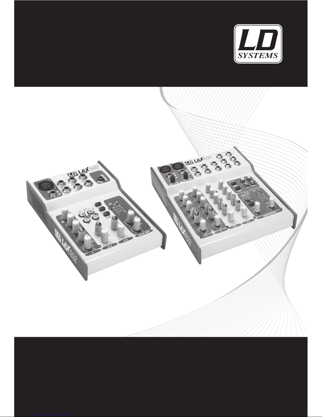
LD LAX SERIES
502 / 602
MIXING CONSOLE
USER´S MANUAL
BEDIENUNGSANLEITUNG
MANUEL D´UTILISATION
MANUAL DE USUARIO
INSTRUKCJA OBSŁUGI
MANUALE D‘USO
Page 2

2
ENGLISHDEUTSCHFRANCAIS
FRANCAISFRANCAIS
FRANCAISFRANCAIS
ESPAÑOLPOLSKIITALIANO
Thank you for choosing LD-Systems!
We have designed this product to give you reliable operation over many years. Therefore LD-Systems underwrites
high quality products with its name and many years of experience as a producer.
Please, take a few moments to read these instructions carefully, as we want you to enjoy your new LD-Systems
products quickly and to the fullest.
Further information about LD-Systems check our website WWW.LD-SYSTEMS.COM
Page 3
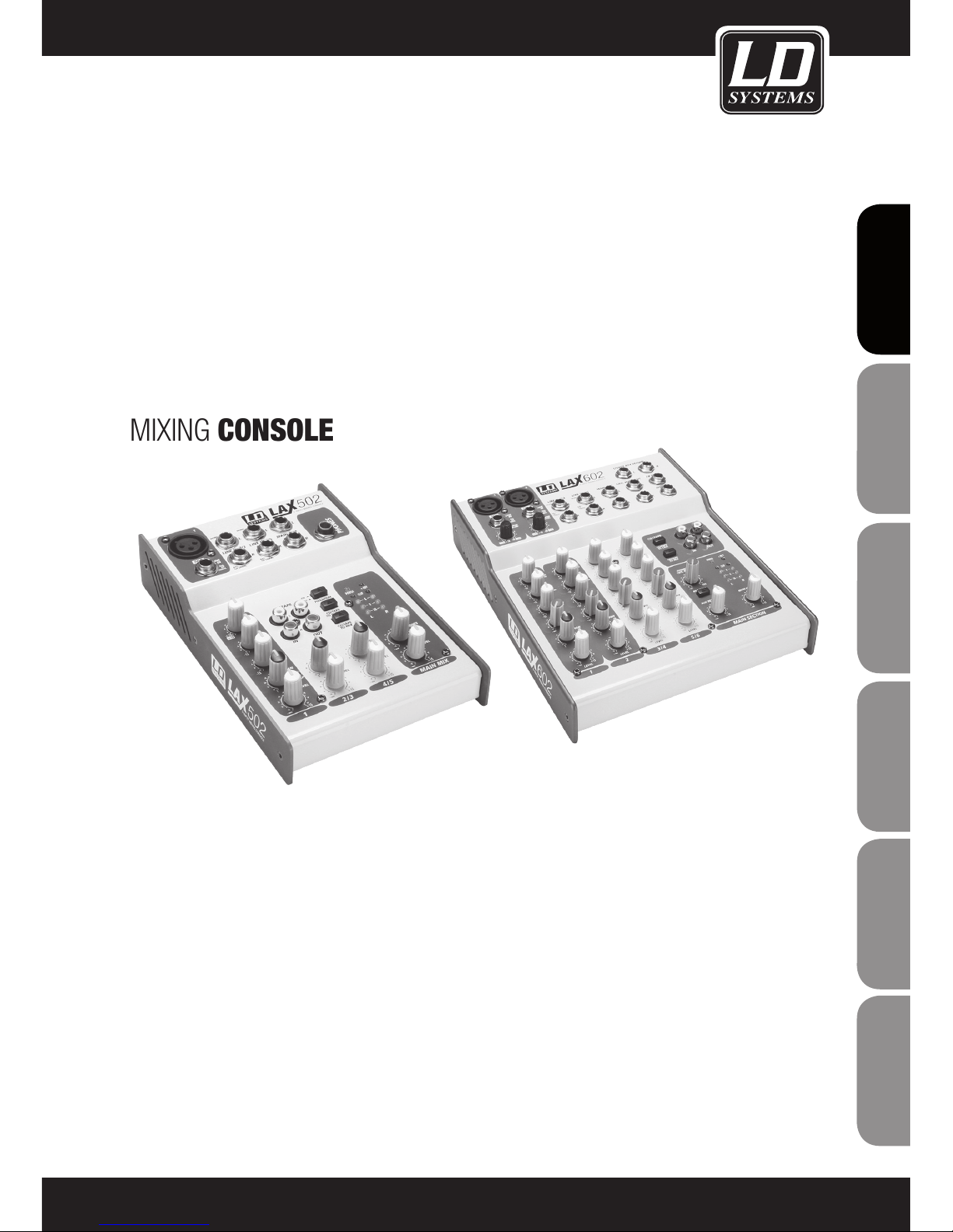
LD LAX SERIES
502 / 602
MIXING CONSOLE
3
ITALIANO
POLSKI
ESPAÑOL
FRANCAIS
FRANCAIS
FRANCAIS
FRANCAIS
FRANCAIS
DEUTSCH
ENGLISH
Page 4
4
ENGLISHDEUTSCHFRANCAIS
FRANCAISFRANCAIS
FRANCAISFRANCAIS
ESPAÑOLPOLSKIITALIANO
PREVENTIVE MEASURES:
1. Please read the attached safety instructions as well as the following instructions carefully.
2. Please keep all the instructions.
3. Please use the device only as intended.
4. Please respect the valid waste management rules. Please deliver the packaging divided into plastic and
paper/ cardboard to the recycling management.
5. Please refer all servicing to qualified personel only if the device is damaged, exposed to liquid/rain or if it does
not operate normally.
6. Please, do not expose to any kind of heat such as ovens, radiators, or any other devices (incl. amplifiers).
Please check for enough distance between amplifiers and walls, racks, etc. to prevent overheating.
7. After connection please check the wiring to prevent any kind of accident or damage.
Please never use any kind of damaged cable and wiring.
8. Only use authorized and stable stands, brackets, shelfs, tables etc.. for installations. Please check for
adequate stability against collapse.
9. Appearance of interferences when using wireless systems.
The simultaneous use of wireless microphones and of mobile phones (if both devices are not very distant from
each other) can lead to the appearance of interferences in the microphone signal which can be heard in the
PA system.
CAUTION:
To reduce the risk of electric shock, do not remove cover (or back). No user serviceable parts inside. Refer
servicing to qualified personnel.
The lightning flash with arrowhead symbol within an equilateral triangle is intended to alert the
user to the presence of uninsulated “dangerous voltage” within the product´s enclosure that may be
of sufficient magnitude to constitute a risk to persons.
The exclamation mark within an equilateral triangle is intended to alert the user to the presence of
important operating and maintenance (servicing) instructions in the literature accompanying the
appliance.
CAUTION! HIGH VOLUME!
You will operate this transmission system for professional use. Therefore the commercial use of this equipment
is liable to the rules and regulations of the Accident Prevention & Insurance Association of your industry sector.
Adam Hall as a manufacturer is bound to inform you formally about the existence of eventual sanitary risks.
This system is able to induce an acoustic pressure of 80 db. 85 db is by law the maximum audio pressure level
which your ear can be exposed to during a work day. It was set according to the technical expertise of the
occupational medicine as a basis for the noise rating level. Higher sound levels or longer exposition times could
damage your ear. The time of exposition by higher sound pressure levels should be shortened in order to prevent
from ear damages. Here are a few reliable warning signals which show that you have exposed yourself for a too
long period to excessive sound pressure levels:
- You hear bell- or whistling sounds!
- You have the impression that you can’t hear high tones anymore!
CAUTION
RISK OF ELECTRIC SHOCK
DO NOT OPEN
Page 5
INTRODUCTION:
Congratulations! In purchasing the LAX 502/602 you have acquired a mixing console whose small size belies its
versatility and audio performance.
With the microphone preamps including phantom power as an option. Balanced line input and a powerful effects
section. The mixing consoles in the LAX Series are optimally equipped for live and studio applications. Owing to
state-of-the-art circuitry your LAX console produces a warm analog sound that is unrivalled. The microphone
channels feature high-end LAX Mic Preamps that compare well with costly outboard preamps in terms of sound
quality and dynamics and boast the following features.
-130 dB dynamic range for an incredible amount of headroom
-A bandwidth ranging from below 10 Hz to over 20 KHz for crystal-clear reproduction of over the finest nuances
-The extremely low-noise and distortion-free circuitry guarantees natural and transparent signal reproduction
-They are perfectly matched to every conceivable microphone with up to 60 dB gain and +48 volt phantom
power supply
-They enable you to use the greatly extended dynamic range of your 24-bit / 192 kHz HD recorder to the full.
Thereby maintaining optimal audio quality
The equalizers used for the LAX Series are based on the legendary circuitry of top-notch consoles made in
Britain, which are renowned throughout the world for their incredibly warm and musical sound character. Even
with extreme gain settings these equalizers ensure outstanding audio quality.
5
ITALIANO
POLSKI
ESPAÑOL
FRANCAIS
FRANCAIS
FRANCAIS
FRANCAIS
FRANCAIS
DEUTSCH
ENGLISH
Page 6
FUNCTIONS / OPERATION:
GENERAL MIXING CONSOLE FUNCTIONS
A mixing console fulfils three main functions:
-Signal processing: Preamplification, level adjustment, mixing of effects. Frequency equalization.
-Signal distribution: Summing of signals to the aux sends for effects processing and monitor mix, distribution to
one or several recording tracks, power amp(s), control room and 2-track outputs.
-Mix: Setting the volume level, frequency distribution and positioning of the individual signals in the stereo field,
level control of the total mix to match the recording devices/crossover/power amplifier(s). All other mixer functions can be included in this main function.
INITIAL OPERATION
Be sure that there is enough space around the unit for cooling purposes and to avoid over-heating please do
not place your mixing console on high-temperature devices such as radiators or power amps. The console is
connected to the mains via the supplied cable. The console meets the required safety standards.
-Never connect the LAX to the power supply unit when the latter is connected to the mains! First connect the
power supply unit to the console, then connect the power supply unit to the mains.
-Please note that all unit must be properly grounded. For your own safety, you should never remove any ground
connectors from electrical devices or power cables, or render them inoperative.
-Please ensure that only qualified people install and operate the mixing console.
6
ENGLISHDEUTSCHFRANCAIS
FRANCAISFRANCAIS
FRANCAISFRANCAIS
ESPAÑOLPOLSKIITALIANO
Page 7
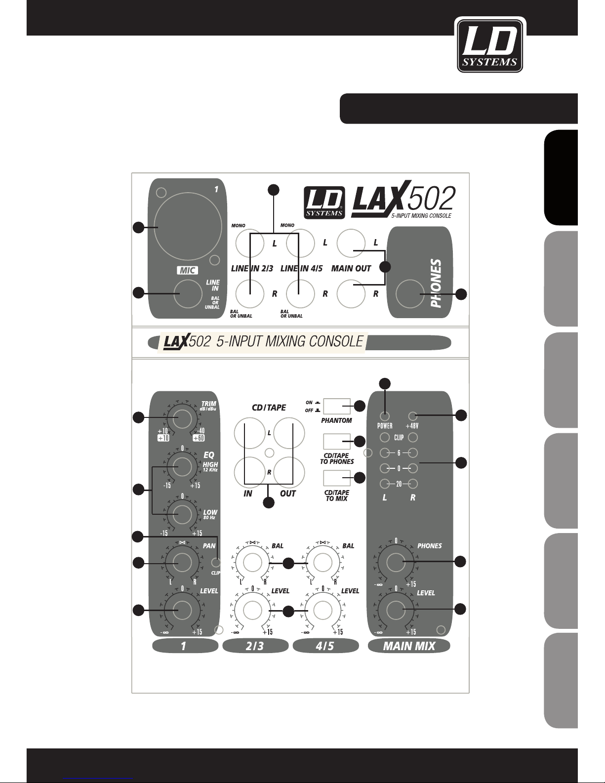
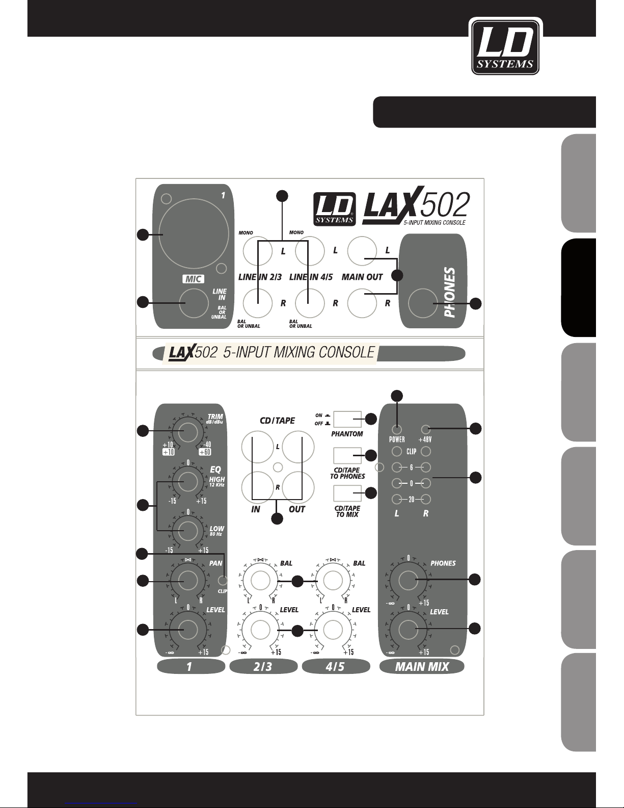
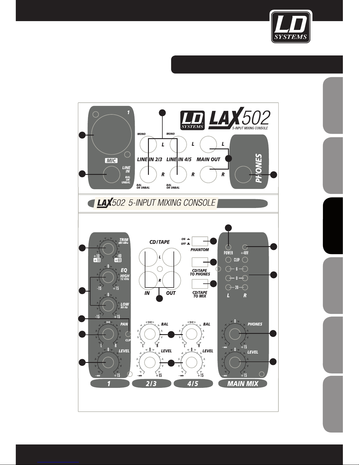
CONTROL ELEMENTS:
7
ITALIANO
POLSKI
ESPAÑOL
FRANCAIS
FRANCAIS
FRANCAIS
FRANCAIS
FRANCAIS
DEUTSCH
ENGLISH
1
2
3
4
5
6
7
8
9
10
11
12
13
14
15
16
18
19
20
21
17
Page 8
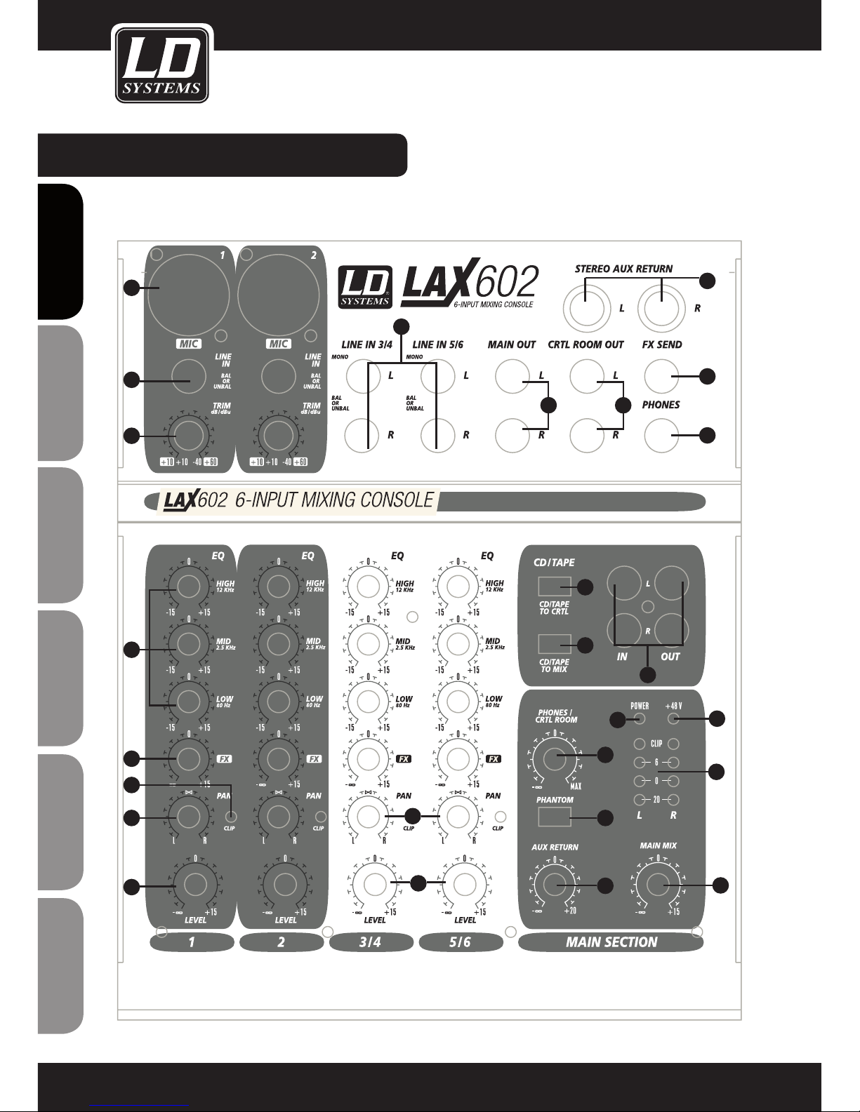
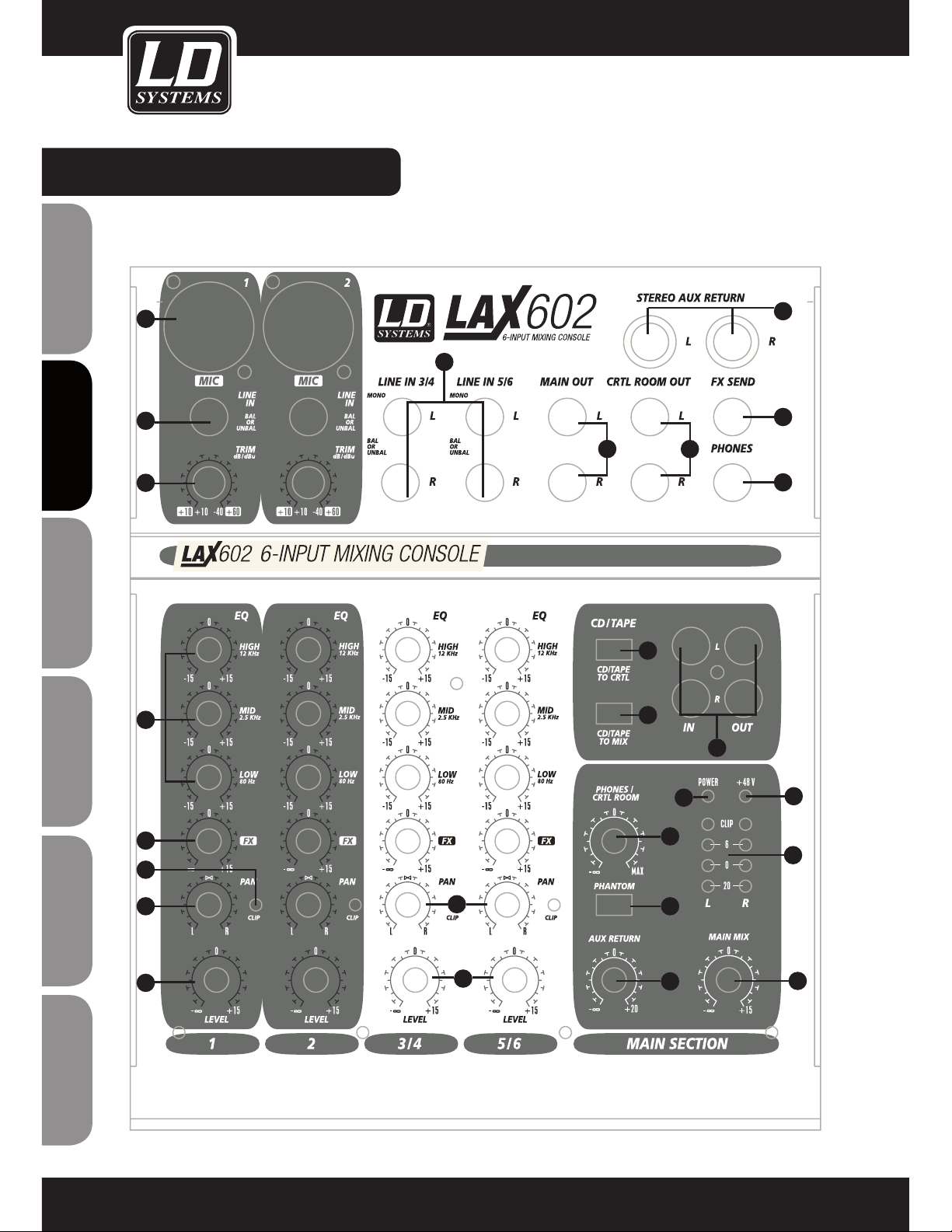
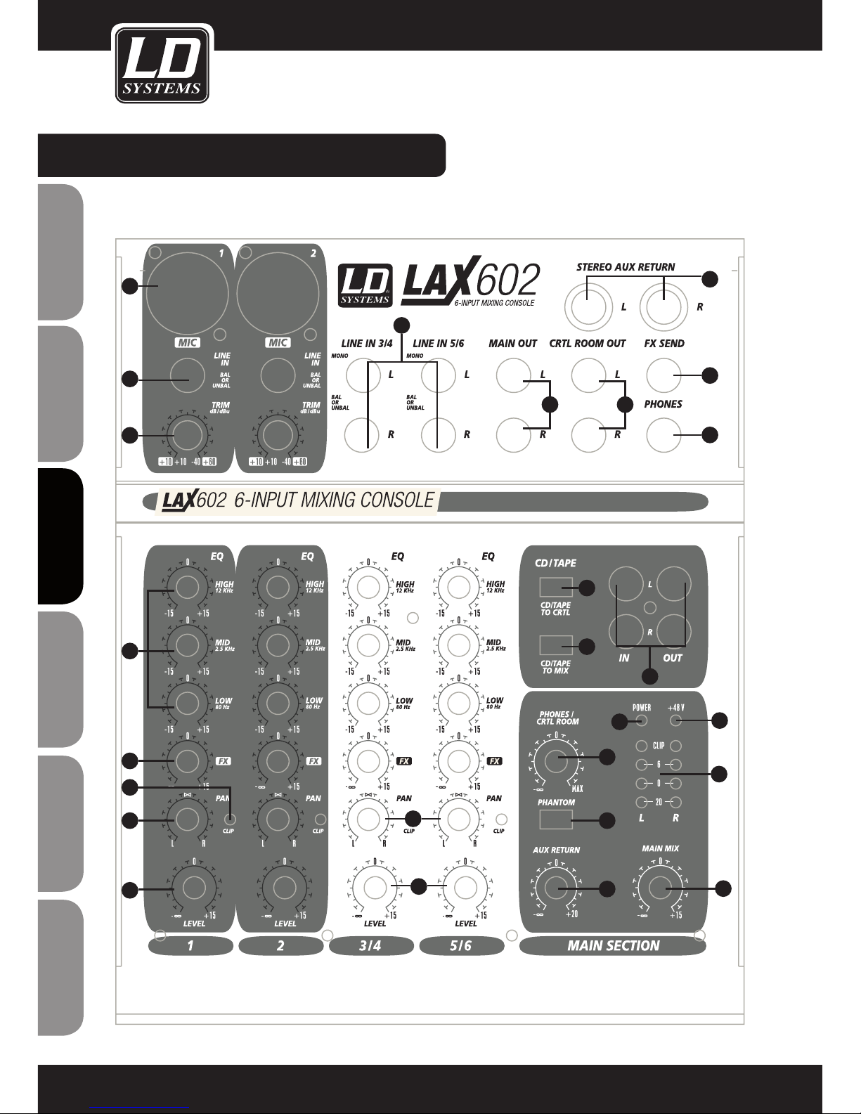
CONTROL ELEMENTS:
8
ENGLISHDEUTSCHFRANCAIS
FRANCAISFRANCAIS
FRANCAISFRANCAIS
ESPAÑOLPOLSKIITALIANO
1
2
3
4
5
6
7
8
9
10
11
12
13
14
15
16
18
19
20
21
17
22
23
26
24
25
Page 9
CONTROL ELEMENTS:
1
MIC
Each mono input channel offers a balanced microphone input via the XLR connector and also features switchable +48 V phantom power supply for condenser microphones. The LAX preamps provide undistorted and
noise-free gain as is typically known only from costly outboard preamps.
2
LINE IN
Each mono input also features a balanced line input on a 6.3 mm Jack connector. Unbalanced devices (mono
jacks) can also be connected to these inputs.
3
TRIM
Use the TRIM control to adjust the input gain. This control should always be turned fully counterclock wise
whenever you connect or disconnect a signal source to one of the inputs.
The scale has 2 different value range: the first value range (+10 to +60 dB) refers to the MIC input and
shows the amplification for the signals fed in there.
The second value range (+10 to -40 dB) refers to the line input and shows its sensitivity.
4
EQ
All mono input channels include a 3-band equalizer (2-band equalizer LAX 502). All bands provide boost or
cut of up to 15 dB. In the central position, the equalizer is inactive.
5
PAN
The PAN control determines the position of channel signal within the stereo image.
6
LEVEL
The LEVEL control determines the level of the channel signal in the main mix
-Attention: Since the FX path for the effect processor is connected post-fader, the LEVEL control has to be
turned up in order to get this channels signal to the effects processor! (EXCEPT LAX 502)
7
CLIP
The CLIP LED´s of the mono channels illuminate when the input signal is driven too high, which could cause
distortion. If this happens, use the TRIM control to reduce the preamp level until the LED does not light
anymore.
8
LINE IN
Each stereo channel has two balanced line level input on 6.3 mm Jack connectors for left and right channels.
If only the connector marked “L”(left) is used, the channel operates in mono. Stereo channels are designed to
handle typical line level signals. Both inputs will also accept unbalanced connectors.
9
BAL
The Balance control determines the levels of left and right input signals relative to each other before both
signal are then routed to the main stereo mix bus. If a channel is operated in mono via the line input, the
control has the same function as the PAN control used in the mono channels.
9
ITALIANO
POLSKI
ESPAÑOL
FRANCAIS
FRANCAIS
FRANCAIS
FRANCAIS
FRANCAIS
DEUTSCH
ENGLISH
Page 10
CONTROL ELEMENTS:
10
LEVEL
The LEVEL control determines the level of the channel signal in the main mix
11
MAIN OUT
The MAIN OUT connectors are unbalanced mono connectors.
12
CD / TAPE
INPUT
The CD/MP3/TAPE INPUTS are used to bring an external signal source (e.g. CD player, tape deck, etc.) into
the console. They can also be used as a standard stereo line input, so the output of a second LAX Mixer.
OUTPUT
These RCA connectors are wired parallel with the MAIN OUT. Connect the inputs of a computer sound card or
a recorder here. The output signal level is setup using the highly accurate MAIN MIX fader.
13
PHONES
6.3 mm stereo jack for headphones.
14
PHONES LEVEL
CONTROL ROOM LEVEL (EXCEPT LAX 502)
Use the PHONES / CONTROL ROOM level to adjust the signal level of the PHONES / CONTROL ROOM output.
15
MAIN MIX LEVEL
Use the MAIN MIX level control to adjust the signal level of the MAIN MIX outputs.
16
PHANTOM POWER
Phantom power is required to operate condenser microphones and is activated using the PHANTOM POWER
switch. (only available for XLR-Mic input)
17
+48V PHANTOM POWER LED
The +48 V LED lights up when phantom power is turned on.
-Caution! You must never use unbalanced XLR connectors (PIN 1 to 3 connected) on the MIC input connectors if you want to use the phantom power supply.
-Please do not connect microphones to the mixer (or the stagebox/wallbox) as long as the phantom power
supply in switched on. Connect the microphones before you switch on the power supply. In addition, the
monitor/PA loudspeakers should be muted before you activate the phantom power supply. After switching on,
wait approx. one minute in order to allow system stabilization.
18
CD/TAPE TO PHONES
CD/TAPE TO CONTROL ROOM (EXCEPT LAX 502)
Press the CD/TAPE TO PHONES / CONTROL ROOM switch if you want to monitor the 2-track input via the
PHONES OUTPUT and CONTROL ROOM OUTPUT.
10
ENGLISHDEUTSCHFRANCAIS
FRANCAISFRANCAIS
FRANCAISFRANCAIS
ESPAÑOLPOLSKIITALIANO
Page 11
CONTROL ELEMENTS:
19
CD/TAPE TO MIX
Press the CD/TAPE TO MIX switch if you want to monitor the 2-track input via the MIX OUTPUT.
20
POWER LED
LED lights up when the Mixer is turned on.
21
SIGNAL AND CLIP LED
The 4-segment level indicator displays the signal level. The CLIP LED´s illuminate when the output signal is
driven too high, which could cause distortion. If this happens, use the MAIN LEVEL control to reduce the main
level until the LED does not light anymore.
22
FX
The FX SEND controls of the stereo channels function similar to those of the mono channels. However, since the
FX send buses are both mono, a mono sum is a first taken from the stereo input before it is sent to the FX bus.
23
FX SEND CONNECTOR
The FX SEND connector outputs the signal you choose from each individual channel using the FX SEND controls.
You can connect this to the input of an external effects device order to process the FX bus master signal. Once
an effects mix is created, the processed signal can then be routed from the effects devices outputs back into a
STEREO LINE INPUT or the STEREO AUX RETURN (only LAX 602).
24
STEREO AUX RETURN (ONLY LAX 602)
The STEREO AUX RETURN connectors are used to bring the output of the external effects device (whose input is
derived from the aux sends) back into the console. You can instead use these connectors as additional inputs,
but any effects device will then have to be brought back into the console via a normal stereo channel. This does,
however, give you the ability to use the channel EQ on the effects return signal if you wish.
-When you are using a stereo channel as effects return path, the FX control of the relevant channel should
generally be turned fully down to avoid undesirable feedback.
25
STEREO AUX RETURN CONTROL (ONLY LAX 602)
Use the AUX RETURN control to determine how much of the effects signal is sent to the main mix. If only the left
connector is used, the AUX RETURN automatically operates in mono.
26
CONTROL ROOM OUT
The unbalanced CTRL ROOM OUT connector carry the summed effects and main mix signals. The PHONE/
CONTROL ROOM control adjusts the level of both headphones and CONTROL ROOM OUTPUTS.
11
ITALIANO
POLSKI
ESPAÑOL
FRANCAIS
FRANCAIS
FRANCAIS
FRANCAIS
FRANCAIS
DEUTSCH
ENGLISH
Page 12
REAR PANEL:
12
ENGLISHDEUTSCHFRANCAIS
FRANCAISFRANCAIS
FRANCAISFRANCAIS
ESPAÑOLPOLSKIITALIANO
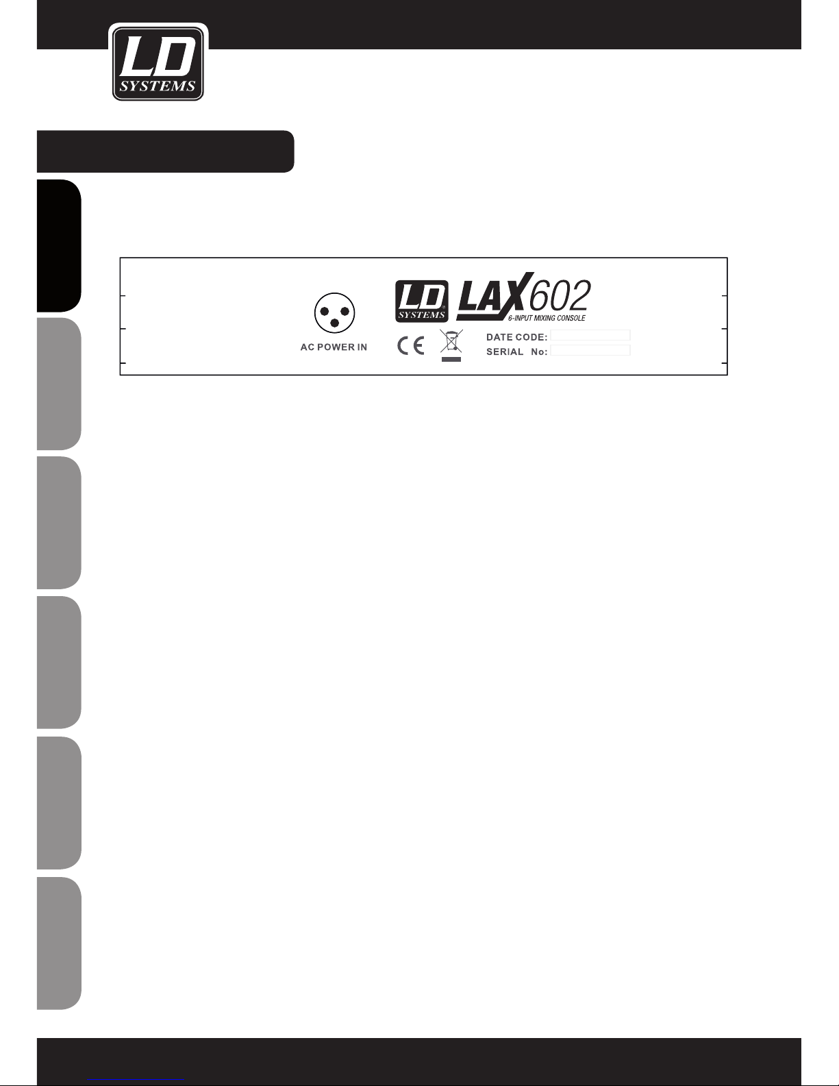
AC POWER IN
Connect the power supply to the 3-pin mains connector on the rear of the console. Use the AC adapter supplied
to connect the console to the mains. The adapter complies with all applicable safety standards.
-Please use only the power supply unit provided with the console.
-Never connect the LAX Mixer to the power supply unit while the latter is connected to the mains! First connect
the console to the power supply unit, then connect the power supply unit to the mains.
Page 13
SPECIFICATIONS:
13
ITALIANO
POLSKI
ESPAÑOL
FRANCAIS
FRANCAIS
FRANCAIS
FRANCAIS
FRANCAIS
DEUTSCH
ENGLISH
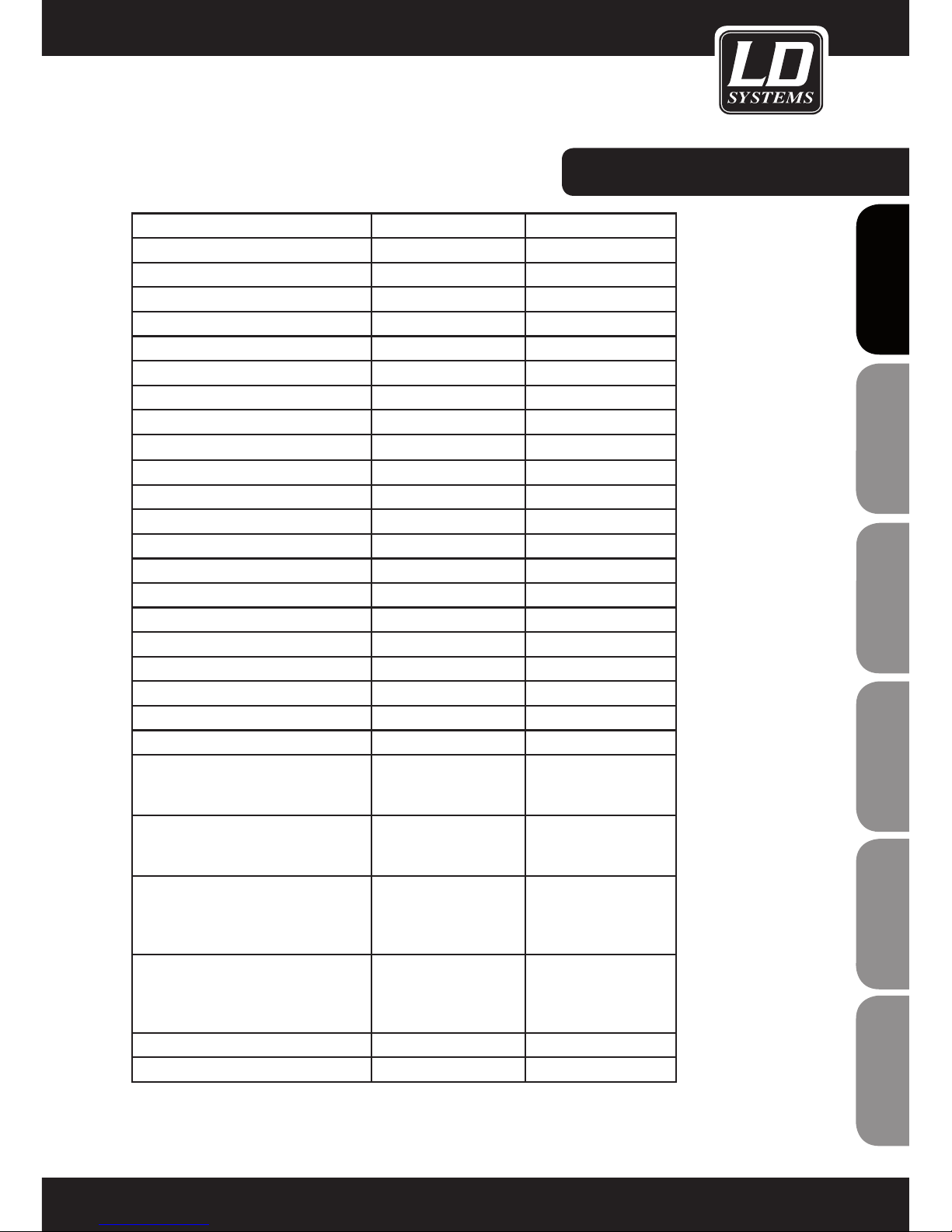
Model Name: LDLAX502 LAX602
Channels: 5 6
Mono Mic and Line Input Channels: 1 2
Mono Mic and Line Input Connectors: XLR, Jack 6,3 mm XLR, Jack 6,3 mm
Stereo Line Input Channels: 2 2
Stereo Line Input Connectors: Jack 6,3 mm mono Jack 6,3 mm mono
AUX / Effects Send Channels: 1
AUX / Effects Send Connectors: Jack 6,3 mm
Stereo AUX Return: 1
AUX Return Connectors: Jack 6,3 mm
Stereo Tape Out: 1 1
Stereo Tape Out Connectors: RCA RCA
Stereo Tape In: 1 1
Stereo Tape In Connenctors: RCA RCA
Stereo Main Out Unbalanced: 1 1
Stereo Main Out Unbalanced Connectors: Jack 6,3 mm Jack 6,3 mm
Stereo Control Room Out: 1
Stereo Control Room Out Connectors: Jack 6,3 mm
Headphones Out: 1 1
Headphones Out Connectors: Jack 6,3 mm Jack 6,3 mm
DFX: No No
Number of presets:
Controls Mono Mic and Line Input
Channels:
Gain, 2-Band EQ, Pan,
Channel Volume
Gain, 3-Band EQ, FX
Send, Pan, Channel
Volume
Controls Stereo Line Input Channels: Balance, Channel Volume 3-Band EQ, FX Send,
Balance, Channel
Volume
Controls Main Section: Phones Volume, Master
Volume, Tape to Phones,
Tape to Mix, Phantom
Power
Phones Volume, Master
Volume, Tape to Phones
/ Control Room, Tape to
Mix, Phantom Power
Indicators: Mono Channel Peak,
Power, 4 Segment Level
Meter, Phantom Power
Mono Channel Peak,
Stereo Channel Peak,
Power, 4 Segment Level
Meter, Phantom Power
Power Supply: external AC Adapter external AC Adapter
Dimensions (W x H x D): 125 x 45 x 195 mm 193 x 55 x 240 mm
Page 14
14
ENGLISHDEUTSCHFRANCAIS
FRANCAISFRANCAIS
FRANCAISFRANCAIS
ESPAÑOLPOLSKIITALIANO
MANUFACTURER‘S WARRANTY
This warranty extends to the LD SYSTEMS branded product you purchased from Adam Hall. The statutory warranty
rights against the vendor shall not be affected by this warranty. Rather, this warranty gives you additional independent
claims against Adam Hall.
With this warranty, Adam Hall ensures that products you have purchased from Adam Hall or Adam Hall partners,
under normal use, are free of defects in material or workmanship for a period of 2 years from the date of purchase.
The warranty period begins on the date of purchase. In order to assert a claim for warranty service, the proof of
date of purchase is provided by the receipt bearing the date of purchase or the date of purchase on the delivery
note. You are entitled to warranty service under the conditions and provisions set out in this document, if a repair
within the warranty period is required.
This warranty applies only to the original purchaser of the products supplied by Adam Hall and is not transferable
to any person to whom the property is transferred by the original purchaser.
Within the warranty period, the defective parts or the product from Adam Hall will be repaired or replaced. Under
the terms of this warranty, all the replaced or removed components become the property of Adam Hall.
In the unlikely event that a product acquired from Adam Hall, repeatedly exhibits a defect, Adam Hall may decide,
at its discretion, to replace this product with a comparable product of at least the same performance.
Adam Hall does not guarantee that the operation of this product will be uninterrupted or error-free. Adam Hall
accepts no responsibility for any damage due to incorrect compliance with the instructions received in the delivery.
This warranty does not extend to:
- wearing parts (eg battery, tubes).
- devices that have had their serial number removed or damaged, or failed as a result of an accident
- inappropriate or abusive use or other external causes
- devices that were not used in accordance with the operating parameters defined in the user documentation
shipped with the product
- devices that have been repaired using parts not made or distributed by Adam Hall
- devices that have been serviced, modified or repaired by someone other than Adam Hall or an authorised service partner.
These terms and conditions constitute the complete and exclusive warranty agreement between you and Adam
Hall regarding the Adam Hall branded product you have purchased.
This warranty is valid only within Europe. Outside of Europe please contact our official distributors.
MANUFACTURER´S DECLARATIONS:
Page 15

15
ITALIANO
POLSKI
ESPAÑOL
FRANCAIS
FRANCAIS
FRANCAIS
FRANCAIS
FRANCAIS
DEUTSCH
ENGLISH
MANUFACTURER´S DECLARATIONS:
LIMITATION OF LIABILITY
If your Adam Hall branded hardware product fails to work as warranted above, your sole and exclusive remedy
shall be repair or replacement. Adam Halls’ maximum liability under this limited warranty is expressly limited to
the lesser of the price you have paid for the product or the cost of repair or replacement of any components that
malfunction under conditions of normal use.
Adam Hall is not liable for any damages caused by the product or the failure of the product, including any lost
profits or savings or special, incidental, or consequential damages. Adam Hall is not liable for any claim made by
a third party or made by you for a third party.
This limitation of liability applies whether damages are sought, or claims are made, under this Limited Warranty
or as a tort claim (including negligence and strict product liability), a contract claim, or any other claim, and
cannot be rescinded or changed by anyone. This limitation of liability will be effective even if you have advised
Adam Hall or an authorized representative of Adam Hall of the possibility of any such damages, but not, however,
in the event of claims for damages in connection with personal injuries.
This manufacturer‘s warranty grants you specific rights; depending on jurisdiction (nation or state), you may be
be entitled to additional claims. You are advised to consult applicable state or national laws for a full determination of your rights.
REQUESTING WARRANTY SERVICE
To request warranty service for the product, contact Adam Hall or the Adam Hall authorized reseller from which
you purchased the product.
EC DECLARATION OF CONFORMITY
The equipment marketed by Adam Hall complies (where applicable) with the essential requirements and other
relevant specifications of Directives 1999/5/EC (R&TTE), 2004/108/EC (EMC) und 2006/95/EC (LVD). Additional
information can be found at www.adamhall.com.
Page 16
16
ENGLISHDEUTSCHFRANCAIS
FRANCAISFRANCAIS
FRANCAISFRANCAIS
ESPAÑOLPOLSKIITALIANO
MANUFACTURER´S DECLARATIONS:
PROPER DISPOSAL OF THIS PRODUCT
(Valid in the European Union and other European countries with waste separation)
This symbol on the product, or the documents accompanying the product, indicates that this appliance may not
be treated as household waste. This is to avoid environmental damage or personal injury due to uncontrolled
waste disposal. Please dispose of this product separately from other waste and have it recycled to promote
sustainable economic activity.
Household users should contact either the retailer where they purchased this product, or their local government
office, for details on where and how they can recycle this item in an environmentally friendly manner.
Business users should contact their supplier and check the terms and conditions of the purchase contract. This
product should not be mixed with other commercial wastes for disposal .
ENVIRONMENTAL PROTECTION AND ENERGY CONSERVATION
Energy conservation is an active contribution to environmental protection. Please turn off all unneeded electrical
devices. To prevent unneeded devices from consuming power in standby mode, disconnect the mains plug.
Adam Hall GmbH, all rights reserved. The technical data and the functional product characteristics can be subject
to modifications. The photocopying, the translation, and all other forms of copying of fragments or of the integrlity
of this user’s manual is prohibited.
Page 17

17
ITALIANO
POLSKI
ESPAÑOL
FRANCAIS
FRANCAIS
FRANCAIS
FRANCAIS
FRANCAIS
DEUTSCH
ENGLISH
Page 18

18
ENGLISHDEUTSCHFRANCAIS
FRANCAISFRANCAIS
FRANCAISFRANCAIS
ESPAÑOLPOLSKIITALIANO
Sie haben die richtige Wahl getroffen!
Diese LD-Systems Produkte werden Sie lange Jahre durch Zuverlässigkeit, Wirtschaftlichkeit und einfaches
Handling überzeugen. Dafür garantiert LD-Systems mit seinem Namen und seiner in vielen Jahren erworbenen
Kompetenz als Hersteller hochwertiger Geräte.
Nehmen Sie sich nun ein paar Minuten Zeit, diese Anleitung zu lesen. Wir möchten, dass Sie einfach und schnell
in den Genuss dieser Technik kommen.
Mehr Informationen zu LD-SYSTEMS finden Sie auf unserer Internetseite WWW.LD-SYSTEMS.COM
Page 19
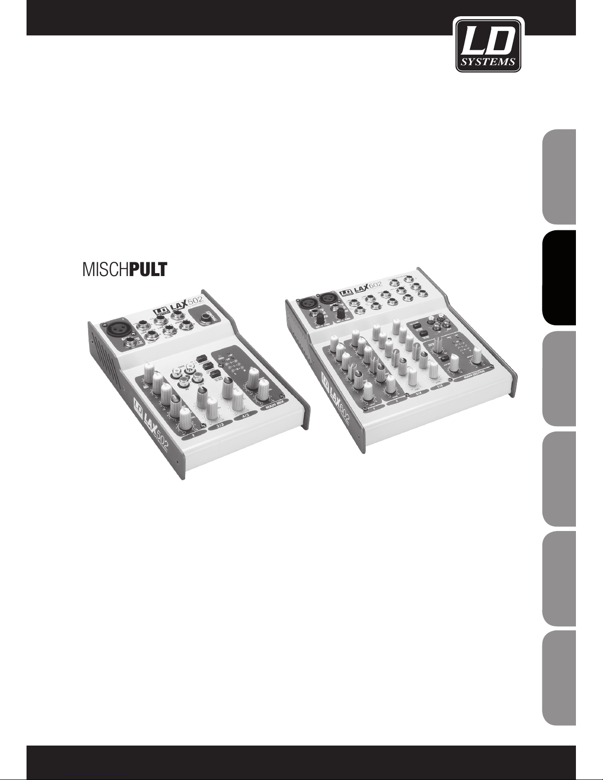
LD LAX-SERIE
502 / 602
MISCHPULT
19
ITALIANO
POLSKI
ESPAÑOL
FRANCAIS
FRANCAIS
FRANCAIS
FRANCAIS
FRANCAIS
DEUTSCH
ENGLISH
Page 20
20
ENGLISHDEUTSCHFRANCAIS
FRANCAISFRANCAIS
FRANCAISFRANCAIS
ESPAÑOLPOLSKIITALIANO
CAUTION
RISK OF ELECTRIC SHOCK
DO NOT OPEN
VORSICHTSMASSNAHMEN:
1. Bitte beachten Sie die Sicherheitshinweise und studieren Sie diese Anleitung sorgfältig.
2. Bewahren Sie alle Hinweise und Anleitungen sicher auf.
3. Verwenden Sie das Gerät nur in der vorgesehenen Art und Weise.
4. Beachten die in Ihrem Land geltenden Entsorgungsgesetze. Trennen Sie bei der Entsorgung bitte Plastik und
Papier bzw. Kartonagen von einander.
5. Sollte Ihr Gerät nicht mehr ordnungsgemäß funktionieren, Flüssigkeiten ausgesetzt werden oder auf sonstige Art
und Weise beschädigt sein, überlassen Sie bitte jegliche Reparaturen ausschließlich autorisiertem Fachpersonal.
6. Halten Sie das Gerät von Hitzequellen wie z.B. Ofen, Heizkörper, oder sonstige Quellen (auch Verstärker) fern.
Sorgen Sie dafür dass das Gerät immer so installiert ist, dass es ausreichend gekühlt wird und nicht überhitzt.
7. Überprüfen Sie alle Verbindungen nach dem Sie das Gerät angeschossen haben um Schäden oder Unfälle zu
vermeiden.
8. Verwenden Sie ausschließlich stabile und passende Stative bzw. Befestigungen wenn das Gerät fest installiert
wird. Stellen Sie sicher, dass das Gerät sicher installiert ist und nicht herunterfallen kann.
ACHTUNG:
Entfernen Sie niemals die Abdeckung, da sonst die Gefahr eines elektrischen Schocks besteht.
Im Inneren des Gerätes befinden sich keine Teile, die vom Bediener gewartet oder repariert werden können.
Lassen Sie Reparaturen ausschließlich von qualifiziertem Servicepersonal durchführen.
Dieses Symbol warnt vor nichtisolierten, gefährlichen Spannungen im Geräteinneren,
die einen gefährlichen Schlag verursachen können.
Dieses Symbol kennzeichnet wichtige Bedienungs- und Wartungshinweise.
Vorsicht! Hohe Lautstärke!
Diese Übertragungsanlage wird von Ihnen professionell eingesetzt. Daher unterliegt der Gebrauch bei gewerblicher Nutzung den Regeln und Vorschriften der zuständigen Berufsgenossenschaft. Adam Hall als Hersteller ist
daher verpflichtet, Sie auf möglicherweise bestehende gesundheitliche Risiken ausdrücklich hinzuweisen.
Mit diesen LAutsprechern können hohe Schalldrücke erzeugt werden. 85db ist der Schalldruck, der laut Gesetz
als maximal zulässiger Wert über die Dauer eines Arbeitstages auf Ihr Gehör einwirken darf. Er wird nach den
Erkenntnissen der Arbeitsmedizin als Berurteilungspegel zu Grunde gelegt. Höhere Lautstärken oder längere
Einwirkzeit können Ihr Gehör schädigen. Bei höheren Lautstärken muss die Hörzeit verkürzt werden, um eine
Schädigung auszuschließen. Sichere Warnsignale dafür, dass Sie sich zu lange zu lautem Geräusch ausgesetzt
haben, sind:
- Sie hören Klingel- oder Pfeifgeräusche in den Ohren!
- Sie haben den Eindruck, hohe Töne nicht mehr wahrzunehmen!
Page 21

EINFÜHRUNG:
Wir freuen uns, dass Sie sich für ein Mischpult der LD LAX-Serie entschieden haben! Mit dem LAX 502/602 haben
Sie ein kompaktes Mischpult erworben, das sich durch eine hohe Audioqualität und Vielseitigkeit auszeichnet.
Mischpulte aus der LAX-Serie verfügen über Mikrofon-Preamps mit Phantomspeisung (zuschaltbar), symmetrische Line-Eingänge und einen leistungsstarken Effektbereich und sind damit für die unterschiedlichsten
Live- und Studioeinsätze optimal ausgestattet. Darüber hinaus gewährleistet die topaktuelle Schaltungstechnik
einen einzigartig warmen Analog-Sound. Die Mikrofonkanäle sind mit Highend-LAX-Mikrofonvorverstärkern ausgestattet, die den Vergleich mit teuren externen Preamps in puncto Klangqualität und Dynamik in keiner Weise zu
scheuen brauchen. Die wichtigsten Features sind:
- 130 dB Dynamik – für reichlich Headroom
- Bandbreite 10 Hz bis 20 kHz – für eine kristallklare Wiedergabe selbst feinster klanglicher Nuancen
- Extrem rauscharme und verzerrungsfreie Schaltungstechnik – für eine natürliche, transparente Signalwieder
gabe
- Perfekte Anpassung an die unterschiedlichsten Mikrofone dank +48-V-Phantomspeisung und bis zu 60 dB Gain
- Ideale Zuspielquelle für 24-Bit/192-kHz-HD-Recorder – für Aufnahmen mit größtmöglicher Dynamik und
erstklassiger Audioqualität
Die Equalizer der LAX-Mischpulte basieren auf der legendären Schaltungstechnik bekannter britischer HighendKonsolen, die dank ihrer unglaublich warmen, "musikalischen" Klangcharakteristik weltweit einen exzellenten
Ruf genießen. Selbst bei extremen Gain-Einstellungen garantieren diese Equalizer stets eine herausragende
Klangqualität.
21
ITALIANO
POLSKI
ESPAÑOL
FRANCAIS
FRANCAIS
FRANCAIS
FRANCAIS
FRANCAIS
DEUTSCH
ENGLISH
Page 22
FUNKTIONEN / BEDIENUNG:
ALLGEMEINE MISCHPULTFUNKTIONEN
Ein Mischpult erfüllt drei Hauptfunktionen:
- Signalverarbeitung: Vorverstärkung, Pegelanpassung, Effektmischung, Frequenzentzerrung (Equalizer).
- Signalverteilung (Routing): Summierung von Signalen und Überführung an AUX-Send-Wege für Effektbearbeitung und Monitormischungen; Verteilung auf eine oder mehrere Aufnahmespuren, Leistungsverstärker,
Regieräume und/oder Stereoausgänge ("2-Track").
- Mischung: Einstellen der Lautstärkepegel, Frequenzverteilung und Positionierung der einzelnen Signale im Stereofeld, Steuerung des Ausgangspegels zur Überführung an Aufnahmegeräte, Frequenzweichen und Leistungsverstärker. Alle weiteren Mischpultfunktionen lassen sich diesen Hauptfunktionen zuordnen.
INBETRIEBNAHME
Sorgen Sie dafür, dass um das Mischpult herum ausreichend Platz ist, so dass das Gerät nicht überhitzt, und
positionieren Sie es nicht auf Wärmequellen wie Heizkörpern oder Leistungsverstärkern. Schließen Sie das
Mischpult mittels des mitgelieferten Netzkabels/Netzteils an das Stromnetz an. Das Pult erfüllt alle erforderlichen
Sicherheitsstandards.
- Schließen Sie niemals das Netzteil an das Mischpult an, wenn das Kabel mit dem Stromnetz verbunden ist!
Verbinden Sie das Netzteil grundsätzlich zuerst mit dem Mischpult, und schließen Sie es dann an das Stromnetz
an.
- Beachten Sie stets die korrekte Erdung. Entfernen Sie im Interesse Ihrer eigenen Sicherheit niemals die Schutzleiter elektrischer Geräte oder Netzkabel, und setzen Sie sie nicht außer Betrieb (z.B. durch Abkleben).
- Gewährleisten Sie stets, dass die Installation und Bedienung des Mischpults durch qualifizierte Personen
erfolgt.
22
ENGLISHDEUTSCHFRANCAIS
FRANCAISFRANCAIS
FRANCAISFRANCAIS
ESPAÑOLPOLSKIITALIANO
Page 23
BEDIENELEMENTE:
23
ITALIANO
POLSKI
ESPAÑOL
FRANCAIS
FRANCAIS
FRANCAIS
FRANCAIS
FRANCAIS
DEUTSCH
ENGLISH
1
2
3
4
5
6
7
8
9
10
11
12
13
14
15
16
18
19
20
21
17
Page 24
BEDIENELEMENTE:
24
ENGLISHDEUTSCHFRANCAIS
FRANCAISFRANCAIS
FRANCAISFRANCAIS
ESPAÑOLPOLSKIITALIANO
1
2
3
4
5
6
7
8
9
10
11
12
13
14
15
16
18
19
20
21
17
22
23
26
24
25
Page 25
BEDIENELEMENTE:
1
MIC
Jeder Mono-Eingangskanal verfügt über einen symmetrischen Mikrofoneingang (XLR-Anschluss) und
zuschaltbare +48-V-Phantomspeisung für Kondensatormikrofone. LAX-Vorverstärker zeichnen sich durch
eine verzerrungs- und rauschfreie Signalverarbeitung aus, wie man sie sonst nur von teuren, externen
Preamps kennt.
2
LINE IN
Zusätzlich verfügt jeder Mono-Eingangskanal über einen symmetrischen Line-Eingang (6,3-mm-Klinke). An
diese Mono-Eingänge können auch unsymmetrische Geräte angeschlossen werden.
3
TRIM
Über die TRIM-Regler stellen Sie die Eingangsverstärkung (Gain) ein. Wenn Sie Signalquellen an das Mischpult anschließen oder wieder trennen, sollte der entsprechende TRIM-Regler grundsätzlich auf Minimum
gedreht werden (ganz nach links).
Die zugehörige Skala zeigt zwei verschiedene Wertebereiche: Der erste Wertebereich (+10 bis +60 dB)
bezieht sich auf den MIC-Eingang und das Verstärkungsmaß des entsprechenden Signals.
Der zweite Wertebereich (+10 bis -40 dB) bezieht sich auf den Line-Eingang und gibt die jeweilige Empfindlichkeit an.
4
EQ
Alle Mono-Eingangskanäle sind mit einem 3-Band-Equalizer (LAX 502: 2-Band-Equalizer) ausgestattet; die
Anhebung bzw. Absenkung beträgt 15 dB. In Mittelstellung bleibt das Signal unbearbeitet, der Equalizer ist
nicht aktiv.
5
PAN
Mit dem PAN-Regler legen Sie die Position des jeweiligen Signals im Stereofeld fest.
6
LEVEL
Mit dem LEVEL-Regler stellen Sie den Pegel des jeweiligen Kanalzugs für die Gesamtmischung ein.
- Achtung: Da der FX-Weg des Effektprozessors “post-fader” geschaltet ist (Signalangriff nach dem KanalLautstärkeregler), muss der LEVEL-Regler nach rechts gedreht werden, um das Signal des entsprechenden
Kanalzugs auf den Effektprozessor zu routen (AUSNAHME: LAX 502)!
7
CLIP
Die CLIP-LEDs der Monokanäle leuchten auf, wenn das Eingangssignal zu hoch ist, da dies zu Verzerrungen
führen kann. Leuchtet die CLIP-LED eines Kanals, reduzieren Sie mittels des TRIM-Reglers den PreampPegel, bis die LED nicht mehr leuchtet.
8
LINE IN
Jeder Stereokanal bietet zwei symmetrische Line-Eingänge (6,3-mm-Klinke, rechter/linker Kanal). Bei
Belegung des linken Anschlusses ("L") arbeitet der Kanal im Monobetrieb. Die Stereokanäle sind für typische
Line-Pegel-Signale ausgelegt und eignen sich auch für unsymmetrische Verbindungen.
25
ITALIANO
POLSKI
ESPAÑOL
FRANCAIS
FRANCAIS
FRANCAIS
FRANCAIS
FRANCAIS
DEUTSCH
ENGLISH
Page 26
BEDIENELEMENTE:
9
BAL
Mit dem Balance-Regler bestimmen Sie die Signalanteile des rechten und des linken Kanals in Relation
zueinander, bevor sie auf den Stereo-Summenbus (MAIN MIX) geroutet werden. Wird der Line-Eingang eines
Stereokanals mit einem Mono-Signal belegt, hat dieser Regler die gleiche Funktion wie die PAN-Regler der
Monokanäle.
10
LEVEL
Mit dem LEVEL-Regler stellen Sie den Pegel des jeweiligen Kanalzugs in der Gesamtmischung ein.
11
MAIN OUT
Die MAIN OUT-Ausgänge (Summenausgänge) sind als unsymmetrische Mono-Ausgänge ausgeführt.
12
CD / TAPE
INPUT
Die CD/MP3/TAPE-Eingänge sind für den Anschluss einer externen Zuspielquelle (z.B. CD-Player, Tapedeck
etc.) vorgesehen. Außerdem können sie als Stereo-Line-Eingänge genutzt werden, z.B. zur Einbindung eines
weiteren LAX-Mixers.
OUTPUT
Diese Cinch-Buchsen sind parallel mit dem Summenausgang (MAIN OUT) verdrahtet, so dass Sie das Ausgangssignal zusätzlich an eine Computer-Soundkarte oder einen Recorder überführen können. Der Pegel des
Ausgangssignals wird über den hochpräzisen Summen-Fader (MAIN MIX) eingestellt.
13
PHONES
6,3-mm-Klinkenanschluss für Kopfhörer (stereo).
14
PHONES LEVEL
CONTROL ROOM LEVEL (AUSSER LAX 502)
Über diesen Regler stellen Sie den Signalpegel des PHONES / CONTROL ROOM-Ausgangs (Kopfhörer/Regie)
ein.
15
MAIN MIX LEVEL
Über den MAIN MIX-Fader stellen Sie den Signalpegel des Stereo-Summenausgangs ein.
16
PHANTOM POWER
Drücken Sie diese Taste, um die für Kondensatormikrofone erforderliche Phantomspeisung einzuschalten
(nur XLR-Mikrofoneingänge).
17
+48 V-LED
Die +48 V-LED leuchtet, wenn die Phantomspeisung aktiviert wurde.
- Achtung! Belegen Sie die MIC-Eingänge niemals mit unsymmetrischen XLR-Verbindungen (Pole 1 und 3
verbunden), wenn Sie Phantomspeisung einsetzen.
26
ENGLISHDEUTSCHFRANCAIS
FRANCAISFRANCAIS
FRANCAISFRANCAIS
ESPAÑOLPOLSKIITALIANO
Page 27
BEDIENELEMENTE:
- Schließen Sie niemals Mikrofone an einen Mixer (oder eine Stagebox bzw. einen Wandverteiler) an, wenn die
Phantomspeisung aktiviert ist. Schalten Sie die Phantomspeisung erst ein, wenn alle Mikrofone angeschlossen
sind. Außerdem sollten die Monitor-/PA-Lautsprecher stummgeschaltet werden, bevor Sie die Phantomspeisung aktivieren. Nach dem Einschalten der Phantomspeisung benötigt das System ungefähr eine Minute zur
Stabilisierung.
18
CD/TAPE TO PHONES
CD/TAPE TO CONTROL ROOM (AUSSER LAX 502)
Drücken Sie die CD/TAPE TO PHONES / CONTROL ROOM-Taste, wenn Sie das Signal des 2-Track-Eingangs
über den Kopfhörer- (PHONES) und Regieausgang (CONTROL ROOM) abhören möchten.
19
CD/TAPE TO MIX
Drücken Sie die CD/TAPE TO MIX-Taste, wenn Sie das Signal des 2-Track-Eingangs über den MIX-Ausgang
abhören möchten.
20
POWER-LED
Diese LED leuchtet, wenn der Mixer eingeschaltet ist.
21
SIGNAL- UND CLIP-LEDs
Die Aussteuerungsanzeige (vier Segmente) zeigt den Signalpegel an. Die CLIP-LEDs leuchten auf, wenn das
Ausgangssignal zu hoch ist, da dies zu Verzerrungen führen kann. Ist das der Fall, reduzieren Sie den Pegel
mittels des Summen-Faders (MAIN MIX), bis die LEDs nicht mehr leuchten.
22
FX
Die FX-SEND-Regler der Stereokanäle funktionieren ähnlich wie die der Monokanäle. Da die FX SEND-Busse
(Effektwege) jedoch mono ausgeführt sind, wird aus dem Stereosignal zunächst ein Monosignal gebildet, das
dann an den FX-Bus überführt wird.
23
FX SEND-AUSGANG
Über den FX SEND-Anschluss werden die per FX SEND-Regler ausgewählten/eingestellten Signale der
einzelnen Kanalzüge ausgegeben. An diesen Ausgang können Sie ein externes Effektgerät anschließen, um so
das Master-Signal des FX-Busses zu bearbeiten. Das bearbeitete Effektsignal (Effekt-Mix) kann anschließend
über die Ausgänge des Effektgeräts wieder zurück auf einen STEREO-LINE-EINGANG oder den STEREO-AUX
RETURN-Weg (nur LAX 602) geroutet werden.
24
STEREO AUX RETURN (NUR LAX 602)
Die STEREO AUX RETURN-Anschlüsse dienen dazu, das Ausgangssignal eines externen Effektgeräts (zur
Bearbeitung der AUX SEND-Signale) zurück in das Mischpult zu überführen. Sie können diese Anschlüsse
auch als zusätzliche Eingänge nutzen. In diesem Fall muss das extern bearbeitete Effektsignal allerdings
über einen normalen Stereokanal zurück in das Mischpult überführt werden – was wiederum den Vorteil mit
sich bringt, dass Sie den Kanal-EQ zur Bearbeitung des Return-Signals nutzen können.
- Wenn Sie einen Stereokanal als FX-Return-Weg nutzen, sollte der FX-Regler des entsprechenden Kanals
unbedingt auf Minimum (ganz nach links) gedreht sein, um unerwünschte Rückkopplungen zu vermeiden.
27
ITALIANO
POLSKI
ESPAÑOL
FRANCAIS
FRANCAIS
FRANCAIS
FRANCAIS
FRANCAIS
DEUTSCH
ENGLISH
Page 28

BEDIENELEMENTE:
25
STEREO AUX RETURN-REGLER (NUR LAX 602)
Über den AUX RETURN-Regler legen Sie den Signalanteil fest, der an die Stereosumme (MAIN MIX) überführt
wird. Ist nur der linke Anschluss belegt, arbeitet der AUX RETURN-Weg automatisch im Monobetrieb.
26
CONTROL ROOM OUT
Am unsymmetrischen CTRL ROOM OUT-Anschluss liegt sowohl die Summe der Effektwege als auch die Stereosumme (MAIN MIX) an. Über den PHONES / CONTROL ROOM-Regler stellen Sie die Pegel für Kopfhörer- und CONTROL
ROOM-AUSGÄNGE ein.
28
ENGLISHDEUTSCHFRANCAIS
FRANCAISFRANCAIS
FRANCAISFRANCAIS
ESPAÑOLPOLSKIITALIANO
Page 29
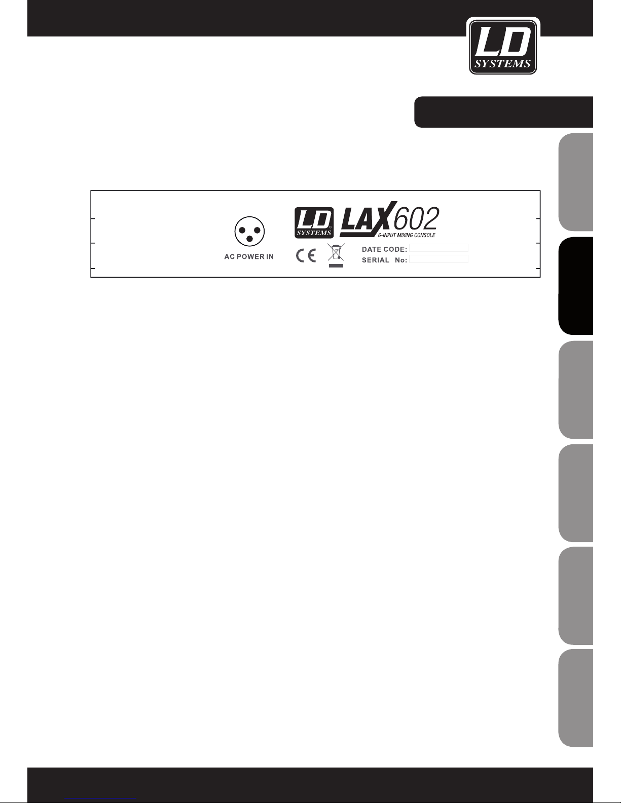
RÜCKSEITE:
AC POWER IN
Verbinden Sie das mitgelieferte Netzteil mit der 3-poligen Netzbuchse (AC POWER IN) auf der Rückseite des
Mischpults, und schließen Sie es an das Stromnetz an. Der Netzadapter entspricht allen erforderlichen Sicherheitsbestimmungen.
- Verwenden Sie ausschließlich das im Lieferumfang des Mischpults enthaltene Netzteil.
- Schließen Sie niemals das Netzteil an das Mischpult an, wenn das Kabel mit dem Stromnetz verbunden ist!
Verbinden Sie das Netzteil grundsätzlich zuerst mit dem Mischpult, und schließen Sie es dann an das Stromnetz
an.
29
ITALIANO
POLSKI
ESPAÑOL
FRANCAIS
FRANCAIS
FRANCAIS
FRANCAIS
FRANCAIS
DEUTSCH
ENGLISH
Page 30
30
ENGLISHDEUTSCHFRANCAIS
FRANCAISFRANCAIS
FRANCAISFRANCAIS
ESPAÑOLPOLSKIITALIANO
TECHNISCHE DATEN:
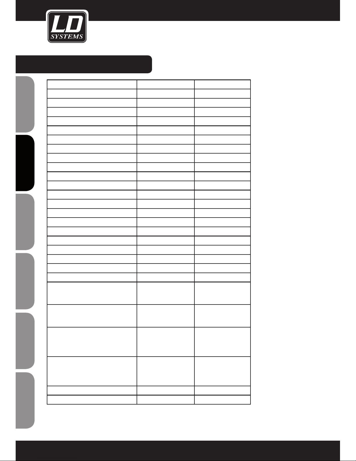
Model Name: LDLAX502 LAX602
Channels: 5 6
Mono Mic and Line Input Channels: 1 2
Mono Mic and Line Input Connectors: XLR, Jack 6,3 mm XLR, Jack 6,3 mm
Stereo Line Input Channels: 2 2
Stereo Line Input Connectors: Jack 6,3 mm mono Jack 6,3 mm mono
AUX / Effects Send Channels: 1
AUX / Effects Send Connectors: Jack 6,3 mm
Stereo AUX Return: 1
AUX Return Connectors: Jack 6,3 mm
Stereo Tape Out: 1 1
Stereo Tape Out Connectors: RCA RCA
Stereo Tape In: 1 1
Stereo Tape In Connenctors: RCA RCA
Stereo Main Out Unbalanced: 1 1
Stereo Main Out Unbalanced Connectors: Jack 6,3 mm Jack 6,3 mm
Stereo Control Room Out: 1
Stereo Control Room Out Connectors: Jack 6,3 mm
Headphones Out: 1 1
Headphones Out Connectors: Jack 6,3 mm Jack 6,3 mm
DFX: No No
Number of presets:
Controls Mono Mic and Line Input
Channels:
Gain, 2-Band EQ, Pan,
Channel Volume
Gain, 3-Band EQ, FX
Send, Pan, Channel
Volume
Controls Stereo Line Input Channels: Balance, Channel Volume 3-Band EQ, FX Send,
Balance, Channel
Volume
Controls Main Section: Phones Volume, Master
Volume, Tape to Phones,
Tape to Mix, Phantom
Power
Phones Volume, Master
Volume, Tape to Phones
/ Control Room, Tape to
Mix, Phantom Power
Indicators: Mono Channel Peak,
Power, 4 Segment Level
Meter, Phantom Power
Mono Channel Peak,
Stereo Channel Peak,
Power, 4 Segment Level
Meter, Phantom Power
Power Supply: external AC Adapter external AC Adapter
Dimensions (W x H x D): 125 x 45 x 195 mm 193 x 55 x 240 mm
Page 31

31
ITALIANO
POLSKI
ESPAÑOL
FRANCAIS
FRANCAIS
FRANCAIS
FRANCAIS
FRANCAIS
DEUTSCH
ENGLISH
HERSTELLERERKLÄRUNGEN:
GARANTIEBESTIMMUNGEN
Diese Garantie erstreckt sich auf das von Ihnen erworbene Adam Hall Produkt der Marke LDSYSTEMS. Die gesetzlichen
Gewährleistungsrechte gegenüber dem Verkäufer werden von dieser Garantie nicht berührt. Vielmehr begründet diese
Garantie zusätzliche selbständige Ansprüche gegenüber Adam Hall.
Mit dieser Garantie stellt Adam Hall sicher, dass das von Ihnen bei Adam Hall oder einem Adam Hall Partner erworbene
Produkt, bei normalem Gebrauch während des Zeitraums von 2 Jahren ab Kaufdatum frei von Material- oder Verarbeitungsfehlern ist. Der Garantiezeitraum beginnt mit dem Datum des Kaufs. Der Geltendmachung eines Anspruchs
auf Garantieleistungen erforderliche Nachweis des Kaufdatums, erfolgt durch die mit dem Kaufdatum versehene
Quittung oder den mit dem Kaufdatum versehenen Lieferschein. Sie haben Anspruch auf den Garantieservice zu den
in diesem Dokument aufgeführten Bedingungen und Bestimmungen, falls eine Reparatur innerhalb des Garantiezeitraums erforderlich ist.
Diese Garantie gilt nur für den ursprünglichen Käufer des von Adam Hall vertriebenen Produkts und ist nicht an
Personen übertragbar, denen vom ursprünglichen Käufer das Eigentum am Adam Hall Produkt übertragen wird.
Innerhalb des Garantiezeitraums werden die fehlerhaften Komponenten oder das Produkt von Adam Hall repariert
oder ersetzt. Alle im Rahmen dieser Garantie ausgetauschten bzw. entfernten Komponenten gehen in das Eigentum
von Adam Hall über.
In dem unwahrscheinlichen Fall, dass bei dem von Ihnen erworbenen Adam Hall Produkt ein Fehler wiederholt auftritt, kann Adam Hall nach eigenem Ermessen entscheiden, Ihnen dieses Produkt durch ein vergleichbares Produkt
mit mindestens derselben Leistung zu ersetzen.
Adam Hall übernimmt keine Garantie für einen störungs- oder fehlerfreien Betrieb dieses Produkts. Adam Hall
übernimmt keine Verantwortung für Schäden die auf eine inkorrekte Befolgung der im Lieferumfang erhaltenen
Anweisungen zurückzuführen sind.
Diese Garantie erstreckt sich nicht auf:
- Verschleißteile (z.B. Akkumulator, Röhren).
- Geräte deren Seriennummer entfernt wurde oder die beschädigt oder fehlerhaft wurden als Folge eines Unfalls
- nicht sachgerechter oder missbräuchlicher Verwendung oder anderer äußerer Ursachen
- Geräte die nicht entsprechend den Betriebsparametern betrieben wurden, die in den im Lieferumfang des Produkts
enthaltenen Benutzerunterlagen festgelegt sind
- Geräte die aufgrund der Verwendung nicht von Adam Hall hergestellter oder vertriebener Teile repariert wurden
- Geräte die durch jemand anderen als Adam Hall oder durch einen autorisierten Servicepartner gewartet, geändert
oder repariert wurden.
Diese Bestimmungen und Bedingungen stellen die vollständige und ausschließliche Garantievereinbarung zwischen
Ihnen und Adam Hall für das von Ihnen erworbene Adam Hall Produkt dar.
Diese Garantie ist nur innerhalb von Europa gültig. Außerhalb von Europa wenden Sie sich bitte an unsere offiziellen
Vertriebspartner.
Page 32

32
ENGLISHDEUTSCHFRANCAIS
FRANCAISFRANCAIS
FRANCAISFRANCAIS
ESPAÑOLPOLSKIITALIANO
HERSTELLERERKLÄRUNGEN:
HAFTUNGSBESCHRÄNKUNG
Falls an Hardware-Produkten von Adam Hall innerhalb der Garantiezeit Material- oder Verarbeitungsfehler
(gemäß der Garantieerklärung oben) auftreten, besteht Ihr alleiniger und ausschließlicher Anspruch aus dieser
Garantie in der Reparatur oder dem Austausch des Geräts. Die maximale Haftung der Firma Adam Hall ist entsprechend dieser Garantie ausdrücklich auf den Kaufpreis oder die Kosten für eine Reparatur oder Ersatz – und
zwar den jeweils niedrigeren Betrag – der bei üblichem Gebrauch fehlerhaften Komponenten begrenzt.
Adam Hall ist nicht haftbar für jegliche durch das Produkt oder das Versagen des Produkts verursachte Schäden,
einschließlich Gewinneinbußen und unterbliebener Einsparungen sowie besonderer, indirekter oder Folgeschäden.
Des Weiteren ist Adam Hall nicht haftbar gegenüber Rechtsansprüchen Dritter oder durch Sie im Namen Dritter
angemeldeten Forderungen.
Diese Haftungsbeschränkung gilt unabhängig davon, ob Schäden gerichtlich verfolgt oder Schadensersatzansprüche im Rahmen dieser Garantie oder aufgrund unerlaubter Handlungen (einschließlich Fahrlässigkeit
und Gefährdungshaftung) oder aufgrund vertraglicher oder sonstiger Ansprüche gestellt werden, und kann von
niemandem aufgehoben oder verändert werden. Diese Haftungsbeschränkung ist auch dann gültig, wenn Sie die
Firma Adam Hall oder einen autorisierten Vertreter von Adam Hall auf die Möglichkeit solcher Schäden aufmerksam
gemacht haben, nicht jedoch bei Schadensersatzansprüchen in Zusammenhang mit Personenschäden.
Diese Herstellergarantie räumt Ihnen bestimmte Rechte ein; je nach Gerichtsbarkeit (Staat oder Land) stehen
Ihnen möglicherweise weitere Ansprüche zu. Es ist ratsam, in solchen Fällen die entsprechenden Gesetze heranzuziehen, um Ihre Rechte umfassend zu ermitteln.
INANSPRUCHNAHME DER GARANTIE
Wenden Sie sich im Garantiefall direkt an Adam Hall oder den von Adam Hall autorisierten Händler, bei dem Sie
das Produkt erworben haben.
EG-KONFORMITÄTSERKLÄRUNG
Die von Adam Hall vertriebenen Geräte entsprechen (soweit zutreffend) den grundlegenden Anforderungen und
weiteren relevanten Spezifikationen der Richtlinien 1999/5/EC (R&TTE), 2004/108/EC (EMC) und 2006/95/EC
(LVD). Weitere Informationen finden Sie unter www.adamhall.com.
Page 33
33
ITALIANO
POLSKI
ESPAÑOL
FRANCAIS
FRANCAIS
FRANCAIS
FRANCAIS
FRANCAIS
DEUTSCH
ENGLISH
KORREKTE ENTSORGUNG DIESES PRODUKTES
(Gültig in der Europäischen Union und anderen europäischen Ländern mit Mülltrennung)
Dieses Symbol auf dem Produkt oder dazugehörigen Dokumenten weist darauf hin, dass das Gerät am Ende der
Produktlebenszeit nicht zusammen mit dem normalen Hausmüll entsorgt werden darf, um Umwelt- oder Personenschäden durch unkontrollierte Abfallentsorgung zu vermeiden. Bitte entsorgen Sie dieses Produkt getrennt von anderen
Abfällen und führen es zur Förderung nachhaltiger Wirtschaftskreisläufe dem Recycling zu.
Als Privatkunde erhalten Sie Informationen zu umweltfreundlichen Entsorgungsmöglichkeiten über den Händler,
bei dem das Produkt erworben wurde, oder über die entsprechenden regionalen Behörden.
Als gewerblicher Nutzer kontaktieren Sie bitte Ihren Lieferanten und prüfen die ggf. vertraglich vereinbarten
Konditionen zur Entsorgung der Geräte. Dieses Produkt darf nicht zusammen mit anderen gewerblichen Abfällen
entsorgt werden.
UMWELTSCHUTZ UND ENERGIESPAREN
Energiesparen ist ein aktiver Beitrag zum Umweltschutz. Schalten Sie bitte alle nicht benötigten elektrischen
Geräte aus. Um zu verhindern, dass nicht benötigte Geräte im Standby-Modus Strom verbrauchen, ziehen Sie
den Netzstecker.
Adam Hall GmbH, alle Rechte vorbehalten. Die technischen Daten und die funktionalen Produkteigenschaften
können Änderungen und Irrtümer vorbehalten. Das Kopieren, die Übersetzung, und alle anderen Formen des
Kopierens von Fragmenten oder der Vollständigkeit dieser Bedienungsanleitung ist untersagt.
HERSTELLERERKLÄRUNGEN:
Page 34

34
ENGLISHDEUTSCHFRANCAIS
FRANCAISFRANCAIS
FRANCAISFRANCAIS
ESPAÑOLPOLSKIITALIANO
Merci d’avoir choisi LD-Systems!
Nous avons conçu ce produit afin de vous offrir un matériel fiable, qui vous accompagnera durant de longues
années. En achetant l’un des produits de la marque LD-Systems vous bénéficiez de notre compétence reconnue
et de nos nombreuses années d’expérience en tant que fabricant. Notre nom est notre garantie.
Veuillez s’il-vous-plait prendre quelques minutes pour lire attentivement ces instructions d’utilisation car nous
souhaitons que vous puissiez profiter pleinement et au plus vite de votre matériel LD-Systems.
Pour plus d’informations sur LD-Systems venez visiter notre site WWW.LD-SYSTEMS.COM
Page 35
LD LAX SERIES
502 / 602
CONSOLE DE MIXAGE
35
ITALIANO
POLSKI
ESPAÑOL
FRANCAIS
FRANCAIS
FRANCAIS
FRANCAIS
FRANCAIS
DEUTSCH
ENGLISH
Page 36
36
ENGLISHDEUTSCHFRANCAIS
FRANCAISFRANCAIS
FRANCAISFRANCAIS
ESPAÑOLPOLSKIITALIANO
MESURESPRÉVENTIVES
CAUTION
RISK OF ELECTRIC SHOCK
DO NOT OPEN
1. Veuillez lire attentivement les précautions d’utilisation et les instructions suivantes.
2. Veuillez conserver ce manuel d’utilisation.
3. Veuillez utiliser cet appareil uniquement conformément à son but d’utilisation initial.
4. Veuillez respecter les règles de traitement des déchets. Veuillez s’il-vous-plait séparer les déchets plastiques
des déchets papiers et les déposer dans un bac à ordures adéquat.
5. En cas de panne, de dommage, d’exposition de l’appareil à la pluie ou autres liquides, veuillez contacter une
personne qualifiée pour le service après-vente de nos produits.
6. Veuillez ne pas exposer ce produit à des sources de chaleur, telles que les fours, les radiateurs ou tout autre
appareil produisant de la chaleur (notamment les amplificateurs de puissance). Pour éviter les risques de
surchauffe veillez à ce que l’appareil ne soit pas placé trop près d’un mur, ou enfermé dans un boitier, pour
que la circulation de l’air ne soit pas obstruée.
7. Après avoir connecté votre appareil veuillez inspecter le câblage pour éviter les risques d’accident ou
d’avarie. Veuillez ne jamais utiliser de câbles endommagés.
8. Veuillez utiliser uniquement les accessoires et supports de fixation fournis ou recommandés par le
constructeur. Assurez vous de la stabilité de votre installation avant d’utiliser votre matériel, vous éviterez les
risques de chutes et donc de dommages de l’appareil.
9. Apparition d’interférences lors de l’usage de systèmes HF sans fil.
L’utilisation simultanée de micros sans fil et de téléphones portables (si les deux appareils sont peu éloignés
l’un de l’autre) peut générer des interférences au niveau du microphone. Ces interférences sont audibles dans
les haut-parleurs de votre système de sonorisation lorsque le système sans fil y est relié.
DANGER:
Pour réduire les risques de choc électrique veuillez ne pas retirer le couvercle (ou la face arrière) de l’appareil.
Les pièces situées à l’intérieur de l’appareil ne doivent pas être manipulées par l’utilisateur. Veuillez contacter
exclusivement une personne qualifiée pour le service après-vente de nos produits.
L’éclair finissant par une flèche, entouré d’un triangle équilatéral vous indique la présence à
l’intérieur du boîtier de pièces non isolées, représentant un risque de “haute tension électrique” et
pouvant par conséquent blesser les personnes.
Le point d’exclamation, entouré d’un triangle équilatéral, vous indique la présence d’instructions
importantes quant-à l’utilisation et à l’entretien dans la brochure fournie avec le produit.
ATTENTION! NIVEAU SONORE ÉLEVÉ!
Vous allez utiliser ce système de transmission sans fil à des fins professionnelles. Dans ce cas l’utilisation de ce
produit est soumise à des règles et à des directives définies par votre organisme professionnel de prévention
des accidents du travail. En tant que fabricant, Adam Hall se doit de vous mettre en garde formellement sur les
risques éventuels que cet appareil peut présenter pour votre santé.
Ce système est capable de générer une pression acoustique supérieure à 80dB. 85dB est la limite légale du
niveau sonore à laquelle votre ouïe peut être soumise lors d’une journée de travail. Cette valeur a été fixée
par la médecine du travail comme valeur de référence pour la mesure du niveau sonore. Vous exposer à des
niveaux sonores plus élevés, ou sur une durée plus longue peut endommager votre ouïe. Si vous vous exposez
à des pressions acoustiques supérieures à la limite légale, pensez à raccourcir le temps d’exposition pour vous
protéger d’éventuelles dégradations de votre ouïe. Voici quelques signes pouvant vous alerter d’une exposition
trop longue à un niveau sonore trop élevé :
- Vous entendez des sons de cloche, de sonnerie ou des sifflements !
- Vous avez l’impression de ne plus entendre les sons aigus !
Page 37

INTRODUCTION:
Félicitations ! Vous venez d'acheter une console de mixage LAX 502/602 : ses dimensions réduites cachent bien
sa polyvalence et ses performances audio.
Grâce à leurs préamplis micro intégrant l'alimentation fantôme, leurs entrées ligne symétriques et leur puissante
section multieffets, les consoles de mixage de la gamme LAX conviennent aussi bien en sonorisation de spectacle vivant qu'en studio. Grâce à ses circuits audio haut de gamme, votre console LAX offre un son analogique
d'une chaleur sans rivale. Les voies micro possèdent des préamplis micro LAX haut de gamme, comparables
à des préamplis externes onéreux en termes de qualité audio et de dynamique, comme le prouvent les chiffres
suivants :
- Gamme dynamique de 130 dB, assurant une incroyable réserve dynamique.
- Une bande passante s'étendant de 10 Hz à plus de 20 kHz, pour une reproduction d'une clarté cristalline,
respectant les nuances les plus fines.
- Les circuits audio, d'un bruit de fond extrêmement bas et sans distorsion, garantissent une reproduction du
signal alliant naturel et transparence.
- Grâce à un gain maximal de 60 dB et à l'alimentation fantôme 48 Volts intégrée, les entrées micro s'adaptent
parfaitement à n'importe quel microphone.
- Les consoles de la gamme LAX sont à la hauteur de la dynamique étendue des enregistreurs HD 24 bits / 192
kHz, et assurent une qualité audio optimale.
Les égaliseurs utilisés sur la gamme LAX sont basés sur les circuits légendaires des consoles de studio anglaises mythiques, renommées dans le monde entier pour leur chaleur et leur incroyable musicalité. Même sur
des signaux de niveau élevé, ces égaliseurs assurent une qualité audio exceptionnelle.
37
ITALIANO
POLSKI
ESPAÑOL
FRANCAIS
FRANCAIS
FRANCAIS
FRANCAIS
FRANCAIS
DEUTSCH
ENGLISH
Page 38
FONCTIONS / UTILISATION :
FONCTIONS DE MIXAGE GLOBALES DE LA CONSOLE
Une console de mixage remplit trois fonctions principales :
- Traitement du signal audio : préamplification, réglage du niveau, ajout d'effets. Égalisation fréquentielle.
- Distribution du signal audio : Prélèvement et sommation des signaux des voies sur les départs auxiliaires (effets, retours...), envoi vers une ou plusieurs pistes en enregistrement, envoi vers des amplificateurs de puissance
(sonorisation), écoute cabine (studio) et enregistreur stéréo.
- Mixage : Réglage du niveau, égalisation fréquentielle, placement des signaux séparés dans l'image stéréo, adaptation du niveau du signal de mixage avant envoi sur enregistreur, filtre actif ou amplificateur(s) de puissance.
Toutes les autres fonctions d'une console entrent dans l'une ou l'autre de ces fonctions principales.
MISE EN PLACE ET PREMIÈRE UTILISATION
Vérifiez qu'il reste assez d'espace libre autour de l'appareil pour assurer un refroidissement correct et pour éviter
toute surchauffe. Veuillez ne pas placer votre console de mixage sur des appareils dégageant de la chaleur, par
exemple un radiateur ou un amplificateur de puissance. Branchez la console sur le secteur par l'intermédiaire du
câble livré. La console est conforme aux normes de sécurité en vigueur.
- Ne branchez jamais la LAX sur son alimentation alors que celle-ci est déjà reliée au secteur ! Commencez
toujours par brancher la console sur son alimentation, puis reliez l'alimentation au secteur.
- Veuillez noter que tous les appareils doivent être mis correctement à la terre. Pour votre propre sécurité, nous
vous recommandons de ne jamais débrancher de connecteur de mise à la terre sur un appareil ou un câble
électrique, ni de rendre la mise à la terre inopérante.
- Assurez-vous que seuls des personnels qualifiés installent et utilisent la console de mixage.
38
ENGLISHDEUTSCHFRANCAIS
FRANCAISFRANCAIS
FRANCAISFRANCAIS
ESPAÑOLPOLSKIITALIANO
Page 39
ÉLÉMENTS DE CONTRÔLE:
39
ITALIANO
POLSKI
ESPAÑOL
FRANCAIS
FRANCAIS
FRANCAIS
FRANCAIS
FRANCAIS
DEUTSCH
ENGLISH
1
2
3
4
5
6
7
8
9
10
11
12
13
14
15
16
18
19
20
21
17
Page 40
ÉLÉMENTS DE CONTRÔLE:
40
ENGLISHDEUTSCHFRANCAIS
FRANCAISFRANCAIS
FRANCAISFRANCAIS
ESPAÑOLPOLSKIITALIANO
1
2
3
4
5
6
7
8
9
10
11
12
13
14
15
16
18
19
20
21
17
22
23
26
24
25
Page 41
ÉLÉMENTS DE CONTRÔLE:
1
MIC
Chaque voie d’entrée mono est équipée d’une entrée micro symétrique sur connecteur XLR, et possède une
alimentation fantôme 48 Volts, permettant d’utiliser un micro statique. Les préamplis micro des consoles LAX
offrent un gain élevé, sans distorsion ni bruit de fond, avec une qualité audio digne de préamplis externes de
prix élevé.
2
LINE IN
Chaque entrée mono est également équipée d’une entrée ligne symétrique sur connecteur jack 6,35 mm.
Cette entrée jack est également compatible avec les sources de signal asymétrqiues (jack mono 2 points).
3
TRIM
Le potentiomètre TRIM sert à régler le gain d’entrée. Il devrait toujours être tourné à fond vers la gauche
lorsque vous connectez ou déconnectez une source de signal sur l’une des entrées.
Sa graduation présente 2 couronnes de valeurs différentes : la première (de +10 à +60 dB) correspond au
gain appliqué sur l’entrée MIC, et indique l’amplification subie par le signal arrivant sur la XLR.
La seconde (de +10 à -40 dB) correspond à l’entrée ligne et indique non le gain apporté, mais la sensibilité
de l’entrée jack.
4
EQ
Toutes les voies d’entrée mono sont équipées d’un égaliseur 3 bandes (2 bandes sur le modèle LAX 502).
Le gain possible est de +/-15 dB sur chaque bande. Lorsque le potentiomètre se trouve en position centrale,
l’égaliseur est inactif.
5
PAN
Le potentiomètre PAN permet de placer le signal de la voie dans l’image stéréo.
6
LEVEL
Le potentiomètre LEVEL dose le niveau du signal de la voie dans le mixage principal (généraux).
- Attention : Comme le départ effets destiné au multieffets interne est prélevés après fader, il faut que le
potentiomètre LEVEL soit ouvert pour que le signal de la voie puisse partir vers le multieffets intégré. (SAUF
LAX 502)
7
CLIP
La LED CLIP s'allume lorsque le signal d'entrée de la voie mono est trop élevé, ce qui pourrait provoquer de
la distorsion. Si c'est le cas, baissez le potentiomètre TRIM, afin de réduire le gain d'entrée, jusqu'à ce que la
LED CLIP ne s'allume plus.
8
LINE IN
Chaque voie stéréo possède deux entrées symétriques au niveau ligne sur connecteurs jack 6,35 mm
(gauche/droite). Si vous n'utilisez que le connecteur repéré "L" (gauche), la voie travaille en mono. Les voies
stéréo sont conçues pour gérer des signaux au niveau ligne. Les deux entrées acceptent aussi les connecteurs asymétriques.
41
ITALIANO
POLSKI
ESPAÑOL
FRANCAIS
FRANCAIS
FRANCAIS
FRANCAIS
FRANCAIS
DEUTSCH
ENGLISH
Page 42
ÉLÉMENTS DE CONTRÔLE:
9
BAL
Le potentiomètre Balance dose les niveaux relatifs des signaux d'entrée du canal gauche et droit avant envoi
au bus de mixage stéréo principal. Si une voie est utilisée en mono (connecteur gauche branché seulement),
le potentiomètre Balance se transforme en potentiomètre PAN (comme dans une voie mono).
10
LEVEL
Le potentiomètre LEVEL dose le niveau du signal de la voie dans le mixage principal (généraux).
11
MAIN OUT
Les connecteurs MAIN OUT sont de type mono asymétrique.
12
CD / TAPE
(ENTRÉES)
Les entrées CD/MP3/TAPE acceptent des sources de signal externes (par exemple : lecteur de CD, enregistreur, etc.). Rien n'empêche de les utiliser en tant qu'entrée ligne stéréo standard, par exemple pour
récupérer la sortie d'une autre console LAX.
OUTPUT
Ces connecteurs RCA sont câblés en parallèle avec la sortie principale des généraux (MAIN OUT). Vous pouvez y connecter, par exemple, les entrées d'une carte son/interface audio d'ordinateur ou d'un enregistreur.
Le niveau du signal de sortie se règle avec précision via le potentiomètre ou le fader MAIN MIX.
13
PHONES
Jack 6,35 mm stéréo pour casque.
14
PHONES LEVEL
CONTROL ROOM LEVEL (SAUF LAX 502)
Le potentiomètre PHONES / CONTROL ROOM sert à doser le niveau du signal présent sur la sortie PHONES /
CONTROL ROOM.
15
MAIN MIX LEVEL
Le potentiomètre/fader MAIN MIX sert à régler le niveau du signal envoyé sur les sorties MAIN MIX.
16
PHANTOM POWER
La tension d'alimentation fantôme est indispensable pour utiliser des micros statiques. Elle s'active via la
touche PHANTOM POWER. (disponible uniquement sur entrée micro XLR)
17
LED +48V
La LED +48V s'allume lorsque l'alimentation fantôme est activée.
- ATTENTION ! N'utilisez jamais de connecteur XLR câblé en asymétrique (points 1 et 3 reliés) sur les entrées
MIC si vous souhaitez activer l'alimentation fantôme.
42
ENGLISHDEUTSCHFRANCAIS
FRANCAISFRANCAIS
FRANCAISFRANCAIS
ESPAÑOLPOLSKIITALIANO
Page 43
ÉLÉMENTS DE CONTRÔLE:
- Ne connectez pas de microphones à la console (ou au boîtier de scène, ou au panneau mural) tant que
l'alimentation fantôme est activée sur la console. Connectez D'ABORD les micros, activez l'alimentation fantôme
ENSUITE. De plus, nous vous conseillons de couper (Mute) les retours ou enceintes de sonorisation façade AVANT
d'activer l'alimentation fantôme. Après activation, veuillez attendre environ 1 minute, pour stabilisation des
circuits électroniques.
18
CD/TAPE TO PHONES
CD/TAPE TO CONTROL ROOM (SAUF LAX 502)
Appuyez sur la touche CD/TAPE TO PHONES / CONTROL ROOM si vous désirez écouter le signal d'entrée
"2-Track" via les sorties PHONES OUTPUT et CONTROL ROOM OUTPUT.
19
CD/TAPE TO MIX
Appuyez sur la touche CD/TAPE TO MIX si vous désirez écouter le signal d'entrée "2-Track" via la sortie MIX
OUTPUT.
20
LED POWER
Cette LED s'allume lorsque la console est sous tension.
21
LED SIGNAL ET CLIP
L’indicateur à 4 segments visualise le niveau du signal. Les LED CLIP s’allument lorsque le signal de sortie
de la console est trop élevé, ce qui pourrait provoquer de la distorsion. Si c’est le cas, baissez le potentiomètre/fader MAIN LEVEL, afin de réduire le niveau de sortie des généraux, jusqu’à ce que les LED CLIP ne
s’allument plus.
22
FX
Les potentiomètres FX SEND des voies stéréo fonctionnent comme ceux des voies mono. Toutefois, comme
les bus de départ FX sont mono, les circuits somment en mono le signal de la voie stéréo avant de l’envoyer
sur le bus FX.
23
CONNECTEUR FX SEND
Le connecteur FX SEND permet de récupérer le signal prélévé sur telle ou telle voie de la console via les
potentiomètres FX SEND. Vous pouvez le relier à l’entrée d’un multieffets externe, pour ajouter un effet au
mixage. Le signal de sortie du multieffets externe est alors réinjecté dans la console par l’intermédiaire d’une
ENTRÉE LIGNE STÉRÉO ou un RETOUR AUXILIAIRE STÉRÉO, AUX RETURN (LAX 602 uniquement).
24
STEREO AUX RETURN (LAX 602 UNIQUEMENT)
Les connecteurs STEREO AUX RETURN servent à réinjecter dans la console le signal de sortie du multieffets
externe (qui recevait, en entrée, le signal d’un bus de départ auxiliaire). Rien ne vous empêche d’utiliser
ces connecteurs en tant qu’entrée stéréo supplémentaire– mais dans ce cas, si vous utilisez un multieffets
externe, vous devrez utiliser une voie stéréo normale pour réinjecter son signal de sortie dans la console.
Avantage, dans ce cas précis : vous pouvez corriger, si désiré, le signal d’effet, via les égaliseurs de la voie
utilisée.
- Si vous utilisez une voie stéréo comme retour effets, n’oubliez pas de couper le potentiomètre de départ FX
de cette voie, afin d’éviter tout phénomène de bouclage indésirable.
43
ITALIANO
POLSKI
ESPAÑOL
FRANCAIS
FRANCAIS
FRANCAIS
FRANCAIS
FRANCAIS
DEUTSCH
ENGLISH
Page 44
ÉLÉMENTS DE CONTRÔLE:
25
POTENTIOMÈTRE STEREO AUX RETURN (LAX 602 UNIQUEMENT)
Le potentiomètre AUX RETURN sert à doser le niveau de retour effets dans le mixage principal. Si vous
n’utilisez que le connecteur repéré “L” (canal gauche), le retour AUX RETURN travaille automatiquement en
mono.
26
CONTROL ROOM OUT
Les connecteurs asymétriques CTRL ROOM OUT permettent de récupérer la somme des signaux des généraux de la console et des effets externes. Le potentiomètre PHONE/CONTROL ROOM agit simultanément sur
le niveau des sorties casque et CONTROL ROOM .
27
FX TO CTRL
Si vous désirez écouter uniquement le niveau de départ effet dans votre casque ou sur les enceintes, appuyez sur la touche FX TO CONTROL ROOM.
28
LOW CUT
Les voies mono possèdent également un filtre passe-haut (LOW CUT) d’action assez énergique, afin
d’atténuer fortement les signaux très graves. Par exemple, bruits parasites de manipulation de micros à
main, composantes infrasonores ou plosives captées par des micros très sensibles.
29
SENSITIVITY +4 / -10
Les voies stéréo possèdent un sélecteur de sensibilité d’entrée à deux positions : +4 dBu et -10 dBV. En position -10 dBV (niveau grand public ou home studio), l’entrée est plus sensible qu’en position +4 dBu (niveau
studio) : autrement dit, elle demande moins de niveau d’entrée pour un niveau de sortie identique.
30
FX SEND
Les départs effets (FX) permettent de prélever des signaux, au niveau désiré, sur une ou plusieurs voies, et
de les sommer sur un bus de sortie FX.
31
FX TO MAIN
Le potentiomètre FX TO MAIN permet de doser la réinjection du signal d’effets dans le mixage principal.
32
PROGRAM
Le potentiomètre PROGRAM possède deux fonctions : Tourner le potentiomètre PROGRAM permet de choisir
le numéro d’un effet. Le numéro du preset ainsi choisi clignote alors à l’affichage. Pour confirmer cette
sélection, appuyez sur le potentiomètre PROGRAM : le clignotement s’arrête.
33
AFFICHAGE
L’affichage indique le numéro du programme d’effet chargé, et contient une LED de présence de signal et
une d’écrêtage. La LED SIGNAL présente sur le module d’effets indique la présence d’un signal de niveau
assez élevé. Cette LED devrait toujours être allumée. Attention : la LED CLIP, elle, ne doit clignoter que très
occasionnellement. Si elle s’allume en permanence, vous surchargez l’entrée du processeur d’effets, ce qui
se traduira par une distorsion gênante. Dans ce cas, baissez un peu le potentiomètre FX SEND.
44
ENGLISHDEUTSCHFRANCAIS
FRANCAISFRANCAIS
FRANCAISFRANCAIS
ESPAÑOLPOLSKIITALIANO
Page 45
PANNEAU ARRIÈRE:
45
ITALIANO
POLSKI
ESPAÑOL
FRANCAIS
FRANCAIS
FRANCAIS
FRANCAIS
FRANCAIS
DEUTSCH
ENGLISH
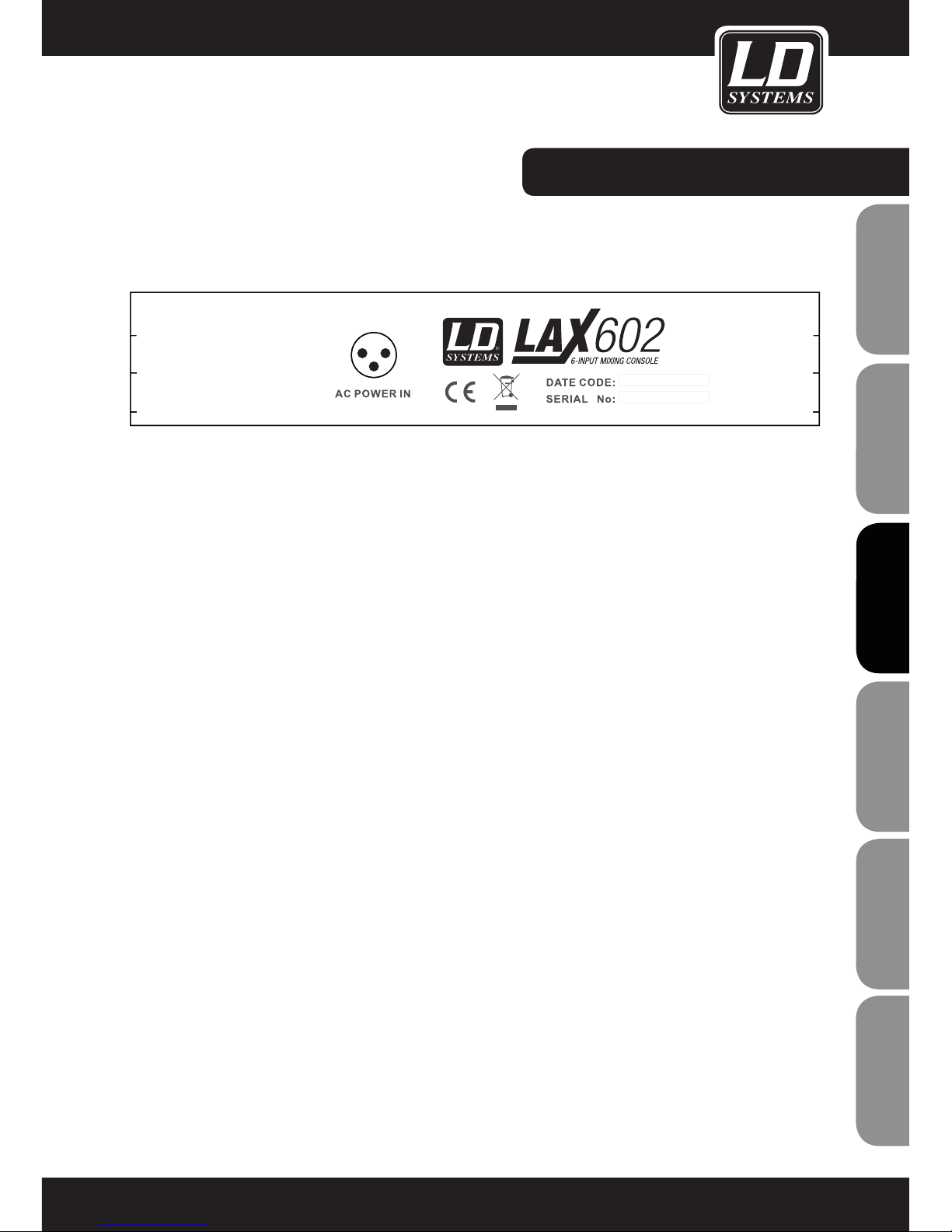
AC POWER IN
Reliez le connecteur de l'alimentation à l'embase 3 points AC POWER IN située à l'arrière de la console. Branchez
ensuite sur une prise secteur l'adaptateur livré avec la console. Cet adaptateur est conforme à toutes les normes
de sécurité applicables.
- Veuillez n'utiliser que l'alimentation secteur livrée avec la console.
- Ne branchez jamais la LAX sur son alimentation alors que celle-ci est déjà reliée au secteur ! Commencez
toujours par brancher la console sur son alimentation, puis reliez l'alimentation au secteur.
Page 46
46
ENGLISHDEUTSCHFRANCAIS
FRANCAISFRANCAIS
FRANCAISFRANCAIS
ESPAÑOLPOLSKIITALIANO
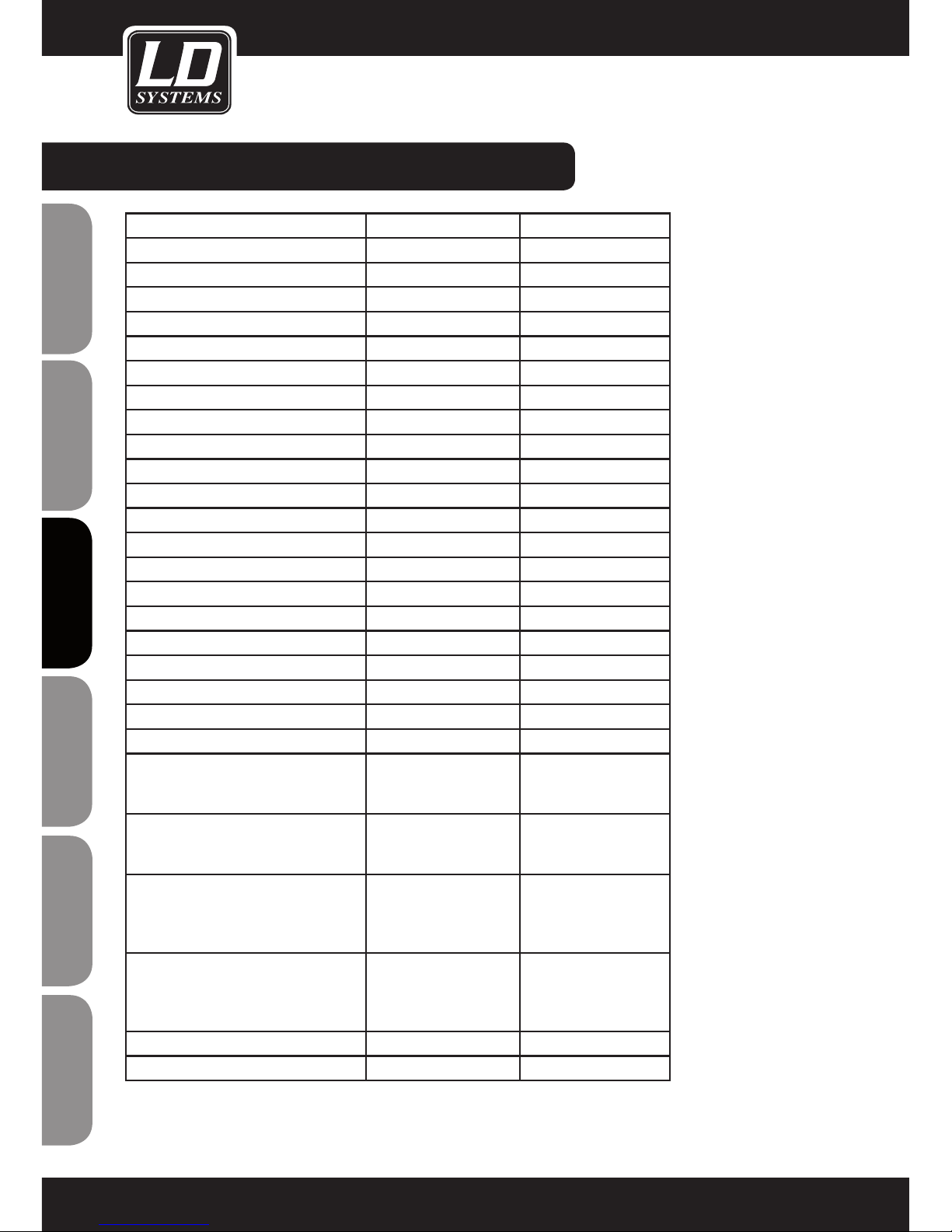
CARACTÉRISTIQUES TECHNIQUES:
Model Name: LDLAX502 LAX602
Channels: 5 6
Mono Mic and Line Input Channels: 1 2
Mono Mic and Line Input Connectors: XLR, Jack 6,3 mm XLR, Jack 6,3 mm
Stereo Line Input Channels: 2 2
Stereo Line Input Connectors: Jack 6,3 mm mono Jack 6,3 mm mono
AUX / Effects Send Channels: 1
AUX / Effects Send Connectors: Jack 6,3 mm
Stereo AUX Return: 1
AUX Return Connectors: Jack 6,3 mm
Stereo Tape Out: 1 1
Stereo Tape Out Connectors: RCA RCA
Stereo Tape In: 1 1
Stereo Tape In Connenctors: RCA RCA
Stereo Main Out Unbalanced: 1 1
Stereo Main Out Unbalanced Connectors: Jack 6,3 mm Jack 6,3 mm
Stereo Control Room Out: 1
Stereo Control Room Out Connectors: Jack 6,3 mm
Headphones Out: 1 1
Headphones Out Connectors: Jack 6,3 mm Jack 6,3 mm
DFX: No No
Number of presets:
Controls Mono Mic and Line Input
Channels:
Gain, 2-Band EQ, Pan,
Channel Volume
Gain, 3-Band EQ, FX
Send, Pan, Channel
Volume
Controls Stereo Line Input Channels: Balance, Channel Volume 3-Band EQ, FX Send,
Balance, Channel
Volume
Controls Main Section: Phones Volume, Master
Volume, Tape to Phones,
Tape to Mix, Phantom
Power
Phones Volume, Master
Volume, Tape to Phones
/ Control Room, Tape to
Mix, Phantom Power
Indicators: Mono Channel Peak,
Power, 4 Segment Level
Meter, Phantom Power
Mono Channel Peak,
Stereo Channel Peak,
Power, 4 Segment Level
Meter, Phantom Power
Power Supply: external AC Adapter external AC Adapter
Dimensions (W x H x D): 125 x 45 x 195 mm 193 x 55 x 240 mm
Page 47

47
ITALIANO
POLSKI
ESPAÑOL
FRANCAIS
FRANCAIS
FRANCAIS
FRANCAIS
FRANCAIS
DEUTSCH
ENGLISH
DECLARATIONS DECLARATIONS :
GARANTIE FABRICANT LIMITÉE
Cette garantie s‘applique au produit Adam Hall de marque LD SYSTEMS que vous avez acheté. Les droits de garantie
légaux à l‘égard du vendeur ne sont pas remplacés par cette garantie. Cette garantie confère au contraire des droits
supplémentaires distincts à l‘égard d‘Adam Hall.
Par cette garantie, Adam Hall assure une garantie de 2 ans à partir de la date d‘achat du produit (auprès d‘Adam
Hall ou d‘un de ses partenaires) contre tout défaut de pièce ou de fabrication, dans le cadre d‘une utilisation
normale. La période de garantie court à partir de la date d‘achat. Pour faire valoir vos droits à la garantie, il faut
justifier de la date d‘achat, soit par une facture datée, soit par un bon de livraison daté. Vous êtes éligible aux droits
relatifs à cette garantie, selon les termes et conditions mentionnés dans ce document , au cas où une réparation
devrait intervenir dans le cadre de la garantie.
Cette garantie n‘est valable que pour l‘acheteur initial du produit Adam Hall ; elle n‘est pas transférable à l‘acheteur
ultérieur du produit.
Tout au long de la période couverte par la garantie, les composants ou le produit défectueux Adam Hall seront
réparés ou remplacés gratuitement. Tous les composants échangés dans le cadre de cette garantie restent la
propriété de Adam Hall.
Dans le cas improbable où le produit Adam Hall que vous avez acheté présenterait une défaillance répétée Adam
Hall peut décider, de son propre chef, de remplacer ce produit par un autre, identique ou comparable (au moins
de la même puissance).
Adam Hall ne garantit pas que l‘utilisation de ce produit ne sera sujette à aucune interruption ni défaillance. Adam
Hall ne peut être tenu pour responsable de dommages consécutifs à une mauvaise observation des instructions
d‘utilisation contenues dans le manuel utilisateur.
Cette garantie ne s‘applique pas dans les cas suivants :
- pièces d‘usure (par exemple, accumulateur, lampe...)
- appareils dont le numéro de série a été supprimé, falsifié ou endommagé suite à un accident
- utilisation non appropriée ou abusive ou autres causes extérieures
- appareils utilisés non conformément aux paramètres d‘utilisation normaux, mentionnés dans le manuel
d‘utilisation livré avec l‘appareil.
- appareils utilisés non conformément aux paramètres d‘utilisation normaux, mentionnés dans le manuel
d‘utilisation livré avec l‘appareil.
- appareils modifiés ou réparés par un tiers autre qu‘Adam Hall ou une structure de maintenance autorisée.
Ces termes et conditions constituent l‘accord de garantie complet et exclusif entre cous et Adam Hall, relativement
au produit de marque Adam Hall que vous avez acheté.
Cette garantie ne s‘applique qu‘en Europe. Hors Europe, veuillez vous adresser à notre représentant commercial officiel.
Page 48

48
ENGLISHDEUTSCHFRANCAIS
FRANCAISFRANCAIS
FRANCAISFRANCAIS
ESPAÑOLPOLSKIITALIANO
DECLARATIONS DECLARATIONS :
RESPONSABILITÉ LIMITÉE
Si votre appareil de marque Adam Hall présente, pendant la période de garantie, des défaillances au niveau des
composants ou de la fabrication, couvertes par les conditions ci avant, le seul recours, exclusif, est sa réparation
ou son remplacement au titre de cette garantie. Dans le cadre de cette garantie limitée, la responsabilité financière maximale d‘Adam Hall est expressément limitée à la plus faible des deux sommes suivantes : prix d‘achat
payé pour le produit ou coût de réparation ou de remplacement de tout composant matériel ne fonctionnant pas
correctement dans des conditions normales d‘utilisation.
Adam Hall ne peut être tenu pour financièrement responsable de tout dommage causé par le produit ou sa
défaillance – y compris toute perte de recettes ou de bénéfices, ni de tout dommage spécifique, incidentel ou
consécutif. De plus, Adam Hall n‘est pas responsable financièrement en cas de requête émanant d‘une tierce
partie ou de votre part pour le compte d‘une tierce partie.
Cette limitation de responsabilité financière s‘applique en cas de demande de dommages et intérêts ou de
poursuites, dans le cadre de cette garantie limitée ou en cas de procédure (négligence et stricte responsabilité
produit), de non-respect du contrat, ou de toute autre procédure. Cette limitation de responsabilité financière
ne peut être annulée ou amendée par quiconque. Cette limitation de responsabilité financière s‘applique même
si vous avez prévenu Adam Hall ou tout représentant autorisé de Adam Hall de la possibilité de tels dommages.
Toutefois, cette limitation de responsabilité financière ne s‘applique pas en cas de blessures aux personnes.
Cette garantie fabricant limitée vous donne des droits légaux spécifiques. Vous pouvez également avoir d‘autres
droits, variables d‘un état ou d‘un pays à l‘autre. Nous vous conseillons de vous reporter aux lois applicables
dans votre état ou votre pays afin de déterminer l‘étendue exacte de vos droits.
DEMANDE DE RÉPARATIONS SOUS GARANTIE
Pour demander des réparations sous garantie pour votre produit, veuillez contacter Adam Hall ou le revendeur
agréé Adam Hall auprès de qui vous l‘avez acheté.
DÉCLARATION DE CONFORMITÉ CE
Les appareils commercialisés par Adam Hall répondent (à la date actuelle) aux exigences et spécifications applicables des Directives 1999/5/EC (R&TTE), 2004/108/EC (EMC) et 2006/95/EC (LVD). Pour plus d‘informations,
référez-vous au site www.adamhall.com.
Page 49
49
ITALIANO
POLSKI
ESPAÑOL
FRANCAIS
FRANCAIS
FRANCAIS
FRANCAIS
FRANCAIS
DEUTSCH
ENGLISH
DECLARATIONS DECLARATIONS :
MISE AU REBUT DE CE PRODUIT
(Applicable dans l‘Union Européenne et les autres pays européens dotés de systèmes de collecte sélective)
La présence de ce logo sur le produit ou son manuel d‘utilisation indique qu‘en fin de vie, il ne doit pas être
jeté avec les autres déchets domestiques. Afin d‘éviter toute atteinte à l‘environnement ou à la santé humaine
pouvant résulter d‘une gestion incontrôlée des déchets, veuillez assurer son recyclage de manière responsable.
Séparez-le des autres types de déchets et recyclez-le, afin de promouvoir la réutilisation durable des ressources
naturelles.
Nous conseillons aux utilisateurs non professionnels de contacter le revendeur chez qui ils ont acheté le produit,
ou un représentant gouvernemental local, pour plus de détails sur le lieu de collecte et la façon de recycler cet
appareil dans le meilleur respect de l‘environnement possible..
Nous invitons les utilisateurs professionnels à contacter leur fournisseur et à vérifier les termes et conditions de
leur contrat d‘achat. Ce produit ne doit pas être mélangé à d‘autres déchets commerciaux lors de la collecte.
PROTECTION DE L'ENVIRONNEMENT ET ÉCONOMIES D'ÉNERGIE
Économiser l'énergie constitue une contribution active efficace à la protection de l'environnement. Pensez à
éteindre tout appareil électrique dès que vous ne vous en servez plus. Pour éviter que les appareils placés en
mode de veille (Standby) ne continuent à consommer de l'électricité, débranchez-les de leur prise secteur.
Adam Hall GmbH, tous droits réservés. Les caractéristiques techniques et les fonctions disponibles sur le produit
sont sujettes à modifications. La photocopie, la traduction et toute forme de copie, partielle ou intégrale, de ce
manuel utilisateur sont interdites.
Page 50

50
ENGLISHDEUTSCHFRANCAIS
FRANCAISFRANCAIS
FRANCAISFRANCAIS
ESPAÑOLPOLSKIITALIANO
Gracias por elegir LD-Systems!
Este producto se ha diseñado para ofrecer una fiabilidad y durabilidad óptima. Los productos de LD-Systems se
caracterizan por su gran calidad, avalada por el prestigio de la marca y una dilatada experiencia como fabricante.
Le rogamos que lea atentamente estas instrucciones para familiarizarse rápidamente con este producto LDSystems y aprovechar al máximo todas las funciones.
Si desea obtener información sobre LD-Systems, visite nuestro sitio web WWW.LD-SYSTEMS.COM
Page 51
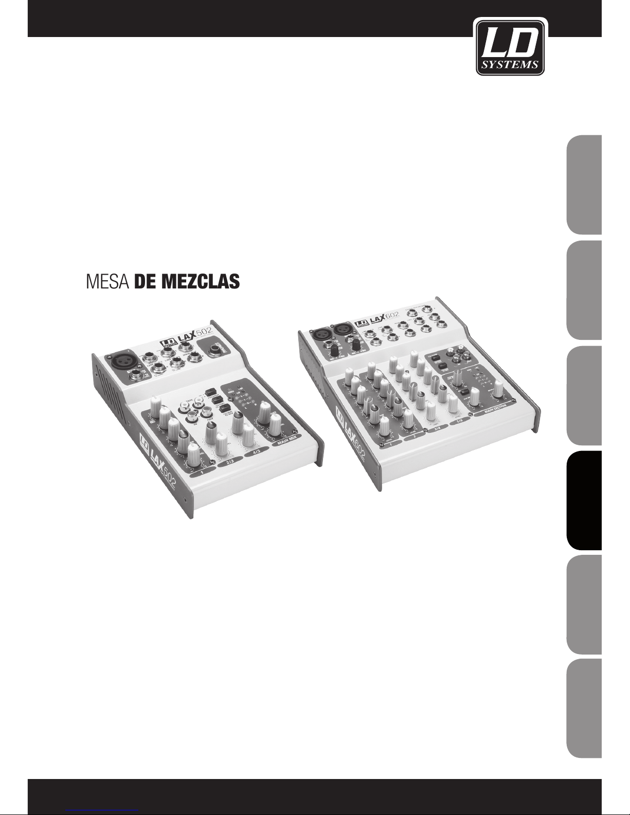
SERIE LD LAX
502 / 602
MESA DE MEZCLAS
51
ITALIANO
POLSKI
ESPAÑOL
FRANCAIS
FRANCAIS
FRANCAIS
FRANCAIS
FRANCAIS
DEUTSCH
ENGLISH
Page 52
52
ENGLISHDEUTSCHFRANCAIS
FRANCAISFRANCAIS
FRANCAISFRANCAIS
ESPAÑOLPOLSKIITALIANO
MEDIDAS PREVENTIVAS:
1. Lea atentamente las instrucciones de seguridad adjuntas así como las instrucciones de este documento.
2. Guarde todas las instrucciones.
3. Utilice el equipo únicamente según la finalidad prevista.
4. Procure seguir las normas vigentes sobre reciclaje de desechos. Separe los componentes de plástico, papel y
cartón del paquete para reciclarlos en sus contenedores respectivos.
5. Acuda a personal de servicio técnico cualificado en caso de que el equipo esté dañado, no funcione correctamente, se haya expuesto a lluvia o haya caído líquido sobre el equipo.
6. Evite colocar el equipo cerca de una fuente de calor, como hornos, radiadores o cualquier otro dispositivo (incluidos los amplificadores). Mantenga una distancia suficiente entre los amplificadores y las paredes, estanterías, etc.
para evitar cualquier sobrecalentamiento.
7. Una vez realizadas todas las conexiones, compruebe el cableado para evitar posibles daños o accidentes.
No utilice cables o conexiones que estén dañados.
8. En la instalación utilice solo soportes, fijaciones, estantes, mesas, etc. que sean estables y estén homologados.
Compruebe que la estabilidad es adecuada para evitar la caída del equipo.
9. Interferencias con los sistemas inalámbricos.
El uso simultáneo de micrófonos inalámbricos y de teléfonos móviles, cuando estos dispositivos están a corta
distancia entre sí, puede provocar interferencias en la señal del micrófono que serán audibles en el sistema de
megafonía.
ADVERTENCIA:
Para evitar el riesgo de descarga eléctrica, no retire la tapa (o el panel posterior). Este equipo no contiene piezas
que puedan ser reparadas por el usuario. Para cualquier tarea de mantenimiento o reparación, acuda a un técnico
cualificado.
El símbolo de rayo dentro de un triángulo equilátero advierte al usuario de la presencia de tensión
peligrosa sin aislamiento dentro de la carcasa del producto que puede ser de magnitud suficiente como
para suponer un riesgo para las personas.
El símbolo de exclamación dentro de un triángulo equilátero advierte al usuario de la existencia de
importantes instrucciones de funcionamiento y mantenimiento (reparaciones) en la documentación
adjunta con el equipo.
¡ADVERTENCIA: ALTO VOLUMEN!
Este sistema de transmisión se destina a un uso profesional. Por consiguiente, si se aplica a un uso comercial, estará sujeto a las normas y reglamentos de la Asociación para la prevención de accidentes de su sector profesional.
Como fabricante, Adam Hall tiene la obligación de informar formalmente a los usuarios de la existencia de posibles
riesgos para la salud.
Este sistema puede producir una presión sonora de 80 dB. Por ley, 85 dB es el nivel de presión sonora máximo
al que puede estar expuesto durante una jornada laboral. Este nivel se estableció a partir de los datos científicos
obtenidos de las investigaciones realizadas en el campo de la medicina del trabajo. Un nivel superior o un tiempo de
exposición mayor pueden provocar daños en su oído. Para no ocasionar lesiones auditivas, el tiempo de exposición
deberá acortarse si aumenta el nivel de presión sonora. Estos son algunos de los síntomas que indican una exposición excesiva a altos niveles de presión sonora:
- Escucha silbidos.
- Le parece que ya no puede oír los tonos agudos.
CAUTION
RISK OF ELECTRIC SHOCK
DO NOT OPEN
Page 53

INTRODUCCIÓN:
¡Enhorabuena! Al adquirir la mesa de mezclas LAX 502/602, cuyas pequeñas dimensiones contrastan con su
versatilidad y prestaciones de audio.
Con el previo de micrófono se incluye la opción de alimentación fantasma. Entrada de línea balanceada y una
amplia gama de efectos. Las mesas de mezclas de la serie LAX están optimizadas para aplicaciones de estudio o
directos. Las mesas de mezclas LAX integran la electrónica más avanzada para lograr un sonido analógico cálido
sin igual. Los canales de micrófono integran unos avanzados previos LAX que son perfectamente comparables a los de modelos de mayor coste en cuanto a calidad y dinámica de sonido, y que ofrecen las siguientes
características:
- Margen dinámico de 130 dB con gran techo dinámico
- Ancho de banda desde 10 Hz a más de 20 kHz para una reproducción fiel del más pequeño matiz
- La electrónica de bajo ruido y sin distorsión garantiza una reproducción natural y transparente
- Se conectan sin problemas a cualquier micrófono, debido a su ganancia de hasta 60 dB y a su alimentación
fantasma de +48 voltios
- Permiten aprovechar al máximo el gran margen dinámico de un grabador HD de 24 bits, 192 kHz. De este
modo, se mantiene la calidad de audio.
Los ecualizadores empleados en la serie LAX se basan en la última tecnología electrónica de las mesas de mezclas británicas, conocidas en todo el mundo por su sonido cálido y musical. Incluso con una ganancia elevada,
estos ecualizadores garantizan una alta calidad de audio.
53
ITALIANO
POLSKI
ESPAÑOL
FRANCAIS
FRANCAIS
FRANCAIS
FRANCAIS
FRANCAIS
DEUTSCH
ENGLISH
Page 54
FUNCIONES Y OPERATIVA:
FUNCIONES GENERALES DE LA MESA DE MEZCLAS
Una mesa de mezclas tiene tres funciones principales:
- Procesamiento de señal: Preamplificación, ajuste de nivel, efectos de mezcla. Ecualización de frecuencias.
- Encaminamiento de señales: Suma de señales en la salida de auxiliar para procesado de efectos y monitorado,
encaminamiento a una o varias pistas de grabación, y a salidas de amplificadores de potencia y monitorado.
- Mezcla: Configuración del nivel, distribución de frecuencias y posicionamiento de las distintas señales en el
espacio estéreo, control de nivel de la mezcla final en función de los equipos de grabación, crossovers y amplificadores. Aquí puede incluirse también el resto de funciones de la mesa de mezclas.
PRIMER USO
Asegúrese de que existe espacio suficiente alrededor del equipo para que se refrigere adecuadamente; para que
no se sobrecaliente, no coloque la mesa de mezclas encima de aparatos que emitan mucho calor, como radiadores y amplificadores de potencia. La mesa de mezclas se conecta al suministro eléctrico mediante el cable
suministrado. La mesa de mezclas cumple con las normas de seguridad correspondientes.
- No conecte la mesa de mezclas LAX al adaptador de corriente si está conectado al suministro eléctrico. Primero conecte el adaptador de corriente a la mesa de mezclas y, a continuación, conecte el adaptador de corriente
al suministro eléctrico.
- Asegúrese de que todos los equipos están correctamente conectados a tierra. Por su propia seguridad, no quite
ni desactive ningún conector a tierra de los equipos eléctricos ni de los cables eléctricos.
- Asegúrese de que una persona cualificada instala y opera la mesa de mezclas.
54
ENGLISHDEUTSCHFRANCAIS
FRANCAISFRANCAIS
FRANCAISFRANCAIS
ESPAÑOLPOLSKIITALIANO
Page 55
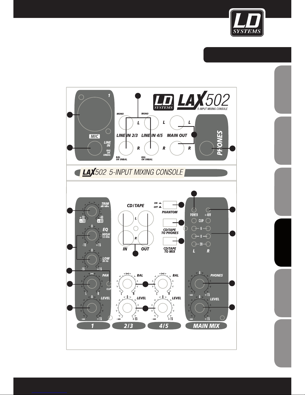
CONTROLES:
55
ITALIANO
POLSKI
ESPAÑOL
FRANCAIS
FRANCAIS
FRANCAIS
FRANCAIS
FRANCAIS
DEUTSCH
ENGLISH
1
2
3
4
5
6
7
8
9
10
11
12
13
14
15
16
18
19
20
21
17
Page 56
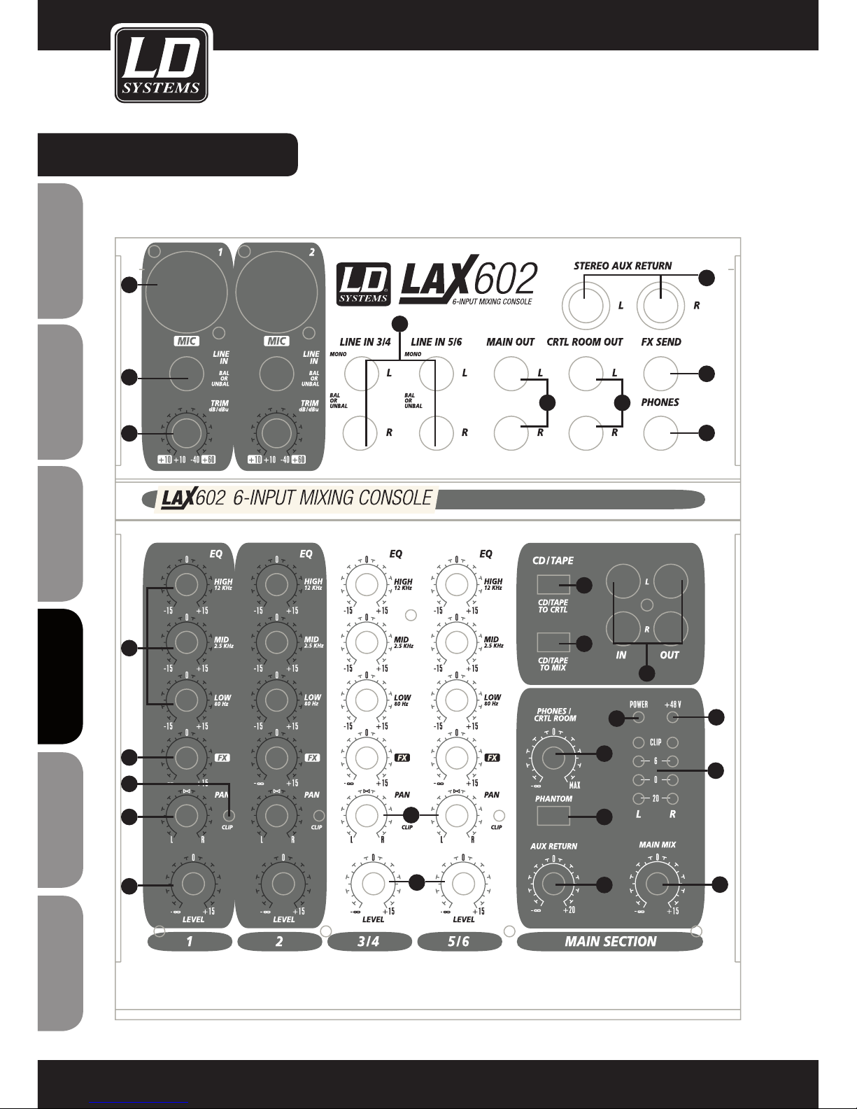
CONTROLES:
56
ENGLISHDEUTSCHFRANCAIS
FRANCAISFRANCAIS
FRANCAISFRANCAIS
ESPAÑOLPOLSKIITALIANO
1
2
3
4
5
6
7
8
9
10
11
12
13
14
15
16
18
19
20
21
17
22
23
26
24
25
Page 57
CONTROLES:
1
MIC
Cada canal de entrada mono tiene una entrada balanceada de micrófono por XLR y una alimentación
fantasma de +48 V conmutable para los micrófonos de condensador. Los previos de la mesa de
mezclas LAX proporcionan una ganancia sin distorsión y sin ruido, presente únicamente en previos de
alto coste.
2
LINE IN
Cada entrada mono dispone también de una entrada de línea balanceada por jack de 6,3 mm. También
es posible conectar a estas entradas equipos de señal no balanceada (jacks mono).
3
TRIM
El control TRIM permite ajustar la ganancia de entrada. Sitúe siempre este control a tope de izquierdas
cuando conecte o desconecte una fuente de señal a una de las entradas.
La escala tiene 2 rangos de valores: el primero (+10 a +60 dB) es para la entrada de micro e indica la
amplificación aplicada a las señales de entrada.
El segundo rango (+10 a -40 dB) es para la entrada de línea e indica la sensibilidad.
4
EQ
Todos los canales de entrada mono integran un ecualizador de 3 bandas (ecualizador de 2 bandas para
LAX 502). Todas las bandas permiten amplificar o atenuar hasta 15 dB. En la posición central, el control
no afecta a la señal.
5
PAN
El control PAN determina la posición del canal en el espacio estéreo.
6
LEVEL
El control LEVEL determina el nivel de señal del canal en la salida principal
- Nota: Como la ruta FX para el procesador de efectos se conecta después del fader, es necesario tener
subido el control LEVEL de estos canales para que llegue la señal al procesador de efectos. (EXCEPTO
LAX 502)
7
CLIP
El LED CLIP de los canales mono se enciende cuando la señal de entrada es demasiado alta y produce
distorsión. Si esto sucede, reduzca el nivel del previo con el control TRIM hasta que se apague el LED.
8
LINE IN
Cada canal estéreo dispone de dos entradas de línea balanceadas por jacks de 6,3 mm, para los canales
izquierdo y derecho. Si sólo se emplea el conector "L" (izquierdo), entonces el canal funciona en mono. Los
canales estéreo están diseñados para señales de nivel de línea. Ambas entradas también aceptan conectores
no balanceados.
57
ITALIANO
POLSKI
ESPAÑOL
FRANCAIS
FRANCAIS
FRANCAIS
FRANCAIS
FRANCAIS
DEUTSCH
ENGLISH
Page 58
CONTROLES:
9
BAL
El control de balance determina los niveles de las señales de entrada izquierda y derecha antes de encaminar ambas señales al bus principal estéreo. Si un canal funciona en mono por la entrada de línea, el control
tiene la misma función que el control PAN de los canales mono.
10
LEVEL
El control LEVEL determina el nivel de señal del canal en la salida principal
11
MAIN OUT
Los conectores MAIN OUT son mono y no balanceados.
12
CD / TAPE
ENTRADA
Las entradas CD/MP3/TAPE se emplean para insertar una señal externa (un reproductor de CD, pletina de
cinta, etc.) en la mesa de mezclas. También pueden emplearse como una entrada de línea estéreo más,
como la salida de otra mesa de mezclas LAX.
SALIDA
Estos conectores RCA están conectados en paralelo con MAIN OUT. Conéctelos a la entrada de la tarjeta
de sonido de un ordenador o un grabador. El nivel de señal de salida se controla de manera precisa con el
fader MAIN MIX.
13
PHONES
Jacks estéreo de 6,3 mm para auriculares.
14
PHONES LEVEL
CTRL ROOM LEVEL (EXCEPTO LAX 502)
Los controles PHONES o CTRL ROOM permiten ajustar la señal de salida PHONES o CTRL ROOM, respectivamente.
15
MAIN MIX LEVEL
El control de nivel MAIN MIX permite ajustar el nivel de señal de las salidas MAIN MIX.
16
PHANTOM (ALIMENTACIÓN FANTASMA)
La alimentación fantasma es necesaria para los micrófonos de condensador y se activa con el botón PHANTOM. (sólo para entrada XLR de micro)
17
LED +48V DE ALIMENTACIÓN FANTASMA
El LED +48V se ilumina cuando está activada la alimentación fantasma.
Atención: Nunca emplee conectores XLR no balanceados (pines 1 y 3 puenteados) en los conectores de
entrada de micro si desea activar la alimentación fantasma.
58
ENGLISHDEUTSCHFRANCAIS
FRANCAISFRANCAIS
FRANCAISFRANCAIS
ESPAÑOLPOLSKIITALIANO
Page 59
CONTROLES:
- No conecte micrófonos a la mesa de mezclas (o a la caja de escenario) si la alimentación fantasma está activada. Conecte los micrófonos antes de activar la alimentación fantasma. Además, debe silenciar los monitores o
altavoces de megafonía antes de activar la alimentación fantasma. Una vez activada, espere aproximadamente
un minuto para que se estabilice el sistema.
18
CD/TAPE TO PHONES
CD/TAPE TO CTRL (EXCEPTO LAX 502)
Pulse el botón CD/TAPE TO PHONES / CTRL para monitorizar la entrada 2-track mediante las salidas PHONES
y CTRL ROOM.
19
CD/TAPE TO MIX
Pulse el botón CD/TAPE TO MIX para monitorizar la entrada 2-track mediante las salidas PHONES y MAIN
OUT.
20
LED POWER
El LED se ilumina cuando la mesa de mezclas está encendida.
21
SEÑAL y LED CLIP
El vúmetro de 4 segmentos indica el nivel de la señal. El LED CLIP se enciende cuando la señal de entrada es
demasiado alta y produce distorsión. Si esto sucede, reduzca el nivel principal con el control MAIN MIX hasta
que se apague el LED.
22
FX
Los controles FX SEND de los canales estéreo funcionan de manera similar a los de canales mono. Sin
embargo, como ambos buses de envío FX son mono, se toma una primera suma mono de la entrada estéreo
antes de enviarla al bus FX.
23
CONECTOR FX SEND
El conector FX SEND envía la señal seleccionada en cada canal mediante los controles FX. Puede conectarlo
a la entrada de un generador de efectos externo para procesar la señal del bus FX. La señal procesada en
este equipo externo puede entonces insertarse de nuevo en una ENTRADA DE LÍNEA ESTÉREO o en los
conectores AUX RETURN (sólo LAX 602).
24
AUX RETURN (SÓLO LAX 602)
Los conectores AUX RETURN se emplean para insertar la salida de procesadores de efectos externos (a
cuya entrada se conecta la salida auxiliar) de nuevo en la mesa de mezclas. También puede emplear estos
conectores como entradas adicionales (en este caso, puede conectar un procesador de efectos a través de
un canal estéreo normal de la mesa de mezclas). De esta manera podrá emplear el ecualizador de la señal
de retorno de efectos.
- Cuando emplea un canal estéreo como retorno de efectos, en general, debería girar completamente a la
izquierda el control FX de dicho canal para evitar realimentaciones.
59
ITALIANO
POLSKI
ESPAÑOL
FRANCAIS
FRANCAIS
FRANCAIS
FRANCAIS
FRANCAIS
DEUTSCH
ENGLISH
Page 60

CONTROLES:
25
CONTROL AUX RETURN (SÓLO LAX 602)
El control AUX RETURN permite fijar el nivel de la señal de efectos enviada al bus principal. Si sólo se emplea
el conector izquierdo, automáticamente AUX RETURN funcionará en mono.
26
CTRL ROOM OUT
El conector CTRL ROOM OUT no balanceado es la señal suma de efectos y la señal principal. El control
PHONES/CTRL ROOM permite ajustar el nivel de salida de auriculares y CTRL ROOM.
60
ENGLISHDEUTSCHFRANCAIS
FRANCAISFRANCAIS
FRANCAISFRANCAIS
ESPAÑOLPOLSKIITALIANO
Page 61
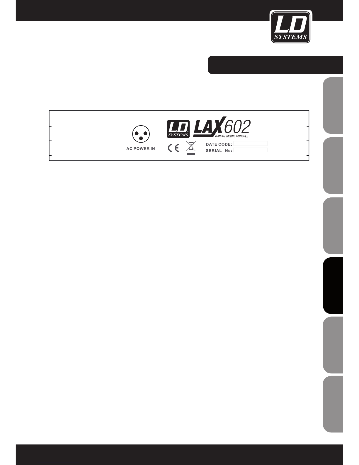
PANEL POSTERIOR:
AC POWER IN
Conecte el adaptador de corriente al conector de 3 pines de la parte posterior de la mesa de mezclas. Emplee
el adaptador de corriente suministrado para conectar la mesa de mezclas al suministro eléctrico. El adaptador
cumple con todas las normas de seguridad correspondientes.
- Emplee únicamente el adaptador de corriente suministrado con la mesa de mezclas.
- No conecte la mesa de mezclas LAX al adaptador de corriente si está conectado al suministro eléctrico. Primero conecte la mesa de mezclas al adaptador de corriente y, a continuación, conecte el adaptador de corriente al
suministro eléctrico.
61
ITALIANO
POLSKI
ESPAÑOL
FRANCAIS
FRANCAIS
FRANCAIS
FRANCAIS
FRANCAIS
DEUTSCH
ENGLISH
Page 62
62
ENGLISHDEUTSCHFRANCAIS
FRANCAISFRANCAIS
FRANCAISFRANCAIS
ESPAÑOLPOLSKIITALIANO
DATOS TÉCNICOS:
Model Name: LDLAX502 LAX602
Channels: 5 6
Mono Mic and Line Input Channels: 1 2
Mono Mic and Line Input Connectors: XLR, Jack 6,3 mm XLR, Jack 6,3 mm
Stereo Line Input Channels: 2 2
Stereo Line Input Connectors: Jack 6,3 mm mono Jack 6,3 mm mono
AUX / Effects Send Channels: 1
AUX / Effects Send Connectors: Jack 6,3 mm
Stereo AUX Return: 1
AUX Return Connectors: Jack 6,3 mm
Stereo Tape Out: 1 1
Stereo Tape Out Connectors: RCA RCA
Stereo Tape In: 1 1
Stereo Tape In Connenctors: RCA RCA
Stereo Main Out Unbalanced: 1 1
Stereo Main Out Unbalanced Connectors: Jack 6,3 mm Jack 6,3 mm
Stereo Control Room Out: 1
Stereo Control Room Out Connectors: Jack 6,3 mm
Headphones Out: 1 1
Headphones Out Connectors: Jack 6,3 mm Jack 6,3 mm
DFX: No No
Number of presets:
Controls Mono Mic and Line Input
Channels:
Gain, 2-Band EQ, Pan,
Channel Volume
Gain, 3-Band EQ, FX
Send, Pan, Channel
Volume
Controls Stereo Line Input Channels: Balance, Channel Volume 3-Band EQ, FX Send,
Balance, Channel
Volume
Controls Main Section: Phones Volume, Master
Volume, Tape to Phones,
Tape to Mix, Phantom
Power
Phones Volume, Master
Volume, Tape to Phones
/ Control Room, Tape to
Mix, Phantom Power
Indicators: Mono Channel Peak,
Power, 4 Segment Level
Meter, Phantom Power
Mono Channel Peak,
Stereo Channel Peak,
Power, 4 Segment Level
Meter, Phantom Power
Power Supply: external AC Adapter external AC Adapter
Dimensions (W x H x D): 125 x 45 x 195 mm 193 x 55 x 240 mm
Page 63

63
ITALIANO
POLSKI
ESPAÑOL
FRANCAIS
FRANCAIS
FRANCAIS
FRANCAIS
FRANCAIS
DEUTSCH
ENGLISH
DECLARACIÓN DEL FABRICANTE:
GARANTÍA DEL FABRICANTE
La presente garantía cubre el producto de la marca LDSYSTEMS que ha adquirido de Adam Hall. No afecta a los
derechos de garantía legal de la que responde el vendedor. De hecho, le concede derechos adicionales ante Adam
Hall, independientes de la garantía legal.
Por la presente, Adam Hall garantiza que el producto que ha adquirido de Adam Hall o de un partner de Adam Hall
estará exento de defectos de material y fabricación, en condiciones normales de uso, durante un período de 2 años
a partir de la fecha de compra. El período de garantía entra en vigor el día de la fecha de compra. Para ejercer su
derecho a la garantía será necesario presentar un justificante de compra válido en el que figure la fecha de compra
del producto, por ejemplo, la factura o el albarán de entrega. Si el producto adquirido necesitara una reparación
dentro del período de garantía, usted tendrá derecho a obtener los servicios de garantía conforme a los términos
y condiciones establecidos en este documento.
La presente garantía se aplica únicamente al comprador original del producto comercializado por Adam Hall y no
es transferible a una tercera persona a la que el comprador original haya transferido la propiedad del producto
Adam Hall.
Durante el periodo de garantía, Adam Hall se compromete a reparar o sustituir las piezas defectuosas o el producto
en cuestión. Todos los componentes substituidos o retirados en el marco de la presente garantía pasarán a ser
propiedad de Adam Hall.
En el caso improbable de que se produzca un fallo recurrente en el producto adquirido, Adam Hall, a su entera
discreción, podrá optar por sustituir dicho producto defectuoso por otro de similares características.
Adam Hall no garantiza el funcionamiento ininterrumpido y sin fallos de este producto. Adam Hall no se hace responsable
de los posibles daños ocasionados por no seguir las instrucciones de uso suministradas con el producto.
Esta garantía no cubre:
- los consumibles (baterías, válvulas, etc.)
- los productos cuyo número de serie ha sido borrado, o que han quedado dañados y defectuosos debido a un accidente
- los defectos ocasionados por un uso incorrecto o indebido, o cualquier otra causa ajena
- los equipos que no se utilizan conforme a los parámetros establecidos en la documentación suministrada con
el producto
- los equipos que no fueron reparados con piezas fabricadas o distribuidas por Adam Hall
- los equipos cuyo mantenimiento, modificación o reparación no haya sido realizado por Adam Hall o uno de sus
servicios técnicos autorizados
Estos términos y condiciones constituyen el acuerdo de garantía íntegro y exclusivo entre usted y Adam Hall en
relación con el producto Adam Hall que acaba de adquirir.
Esta garantía sólo es válida dentro de Europa. Fuera de Europa deberá dirigirse a nuestros distribuidores oficiales.
Page 64
64
ENGLISHDEUTSCHFRANCAIS
FRANCAISFRANCAIS
FRANCAISFRANCAIS
ESPAÑOLPOLSKIITALIANO
DECLARACIÓN DEL FABRICANTE:
LIMITACIÓN DE RESPONSABILIDAD
Si durante el período de garantía aparecen defectos de material o de fabricación en su producto Adam Hall (de
acuerdo con las garantías mencionadas en este documento), tendrá derecho exclusivamente a la reparación o
sustitución del mismo. La responsabilidad máxima de Adam Hall en virtud de los términos de esta garantía está
limitada al menor importe que resulte del precio de compra del producto, del coste de la reparación o la sustitución de las piezas que han dejado de funcionar en condiciones normales de uso.
Adam Hall no será responsable de ningún daño causado por el producto o por el mal funcionamiento del
producto, incluidas la pérdida de beneficios, la pérdida de ahorros o cualquier consecuencia derivada de dichas
pérdidas. Además, Adam Hall no se hará responsable de ninguna reclamación presentada por un tercero o por el
comprador original en nombre de un tercero.
Esta limitación de responsabilidad se aplicará con independencia de que se solicite una indemnización por daños
y perjuicios, o se presenten reclamaciones por negligencia, contractuales o de cualquier otra índole, y no podrá
ser derogada o modificada. Esta limitación de responsabilidad será efectiva incluso en el caso de que el comprador hubiese avisado previamente a Adam Hall o a alguno de sus representantes de la posibilidad de reclamar
daños y perjuicios. No obstante, esta limitación de responsabilidad no tendrá efecto en caso de reclamación por
daños personales.
Esta garantía limitada le otorga derechos legales específicos. Puede que posea derechos adicionales conforme a
la legislación del país o Estado en el que se encuentre. Le recomendamos que consulte la legislación vigente en
su país o Estado para conocer el alcance de sus derechos.
APLICACIÓN DE LA GARANTÍA
Para solicitar asistencia técnica en relación con el producto en garantía, póngase en contacto con Adam Hall o
con el distribuidor autorizado donde adquirió el producto.
DECLARACIÓN CE DE CONFORMIDAD
Los productos distribuidos por Adam Hall cumplen (según proceda) los requisitos esenciales de las Directivas
europeas 1999/5/CE (Equipos radioeléctricos y equipos terminales de telecomunicación, R&TTE), 2004/108/
CE (Compatibilidad Electromagnética) y 2006/95/CE (Baja Tensión), así como las correspondientes cláusulas
adicionales. Para más información consulte www.adamhall.com.
Page 65
65
ITALIANO
POLSKI
ESPAÑOL
FRANCAIS
FRANCAIS
FRANCAIS
FRANCAIS
FRANCAIS
DEUTSCH
ENGLISH
DECLARACIÓN DEL FABRICANTE:
ELIMINACIÓN CORRECTA DE ESTE PRODUCTO
(Aplicable en la Unión Europea y en los países europeos que dispongan de un sistema de recogida selectiva)
El símbolo que aparece sobre el producto o en la documentación adjunta indica que al final de la vida útil del
equipo, no deberá desecharlo con los demás residuos domésticos, con el fin de evitar posibles efectos negativos
en el medio ambiente y en la salud humana debidos al vertido incontrolado de desechos. La recogida selectiva
ayuda a su posterior reciclaje y fomenta la reutilización sostenible de los componentes de este equipo.
Si es un particular, póngase en contacto con el distribuidor donde adquirió este producto, o con el ayuntamiento,
para informarse sobre el reciclaje adecuado de este equipo.
Si es una empresa, póngase en contacto con su proveedor para informarse sobre los términos y condiciones de
su contrato de compra-venta. Este producto no debe mezclarse con otros residuos industriales.
PROTECCIÓN MEDIOAMBIENTAL Y AHORRO ENERGÉTICO
Ahorre energía eléctrica para proteger el medio ambiente. Para ello, apague todos los aparatos eléctricos cuando
no estén en uso. Además, para evitar el consumo de energía en modo En espera, desenchufe todo aparato
eléctrico de la toma de corriente cuando no esté en uso.
Adam Hall GmbH. Todos los derechos reservados. Los datos técnicos y las características funcionales del producto están sujetos a modificaciones. Se prohíbe la fotocopia, traducción y cualquier otra forma de reproducción
parcial o total de este manual de usuario.
Page 66

66
ENGLISHDEUTSCHFRANCAIS
FRANCAISFRANCAIS
FRANCAISFRANCAIS
ESPAÑOLPOLSKIITALIANO
Dziękujemy za wybór LD Systems!
Zaprojektowaliśmy ten produkt tak, aby działał sprawnie przez wiele lat. LD-Systems gwarantuje wysoką jakość
produktów swoją marką i wieloma latami doświadczenia jako producent.
Prosimy abyś zapoznał się dokładnie z niniejszą instrukcją, ponieważ chcemy abyś szybko mógł cieszyć się w
pełni swoim nowym produktem LD Systems.
Więcej informacji na temat LD Systems znajdziesz na naszej stronie internetowej: WWW.LD-SYSTEMS.COM
Page 67
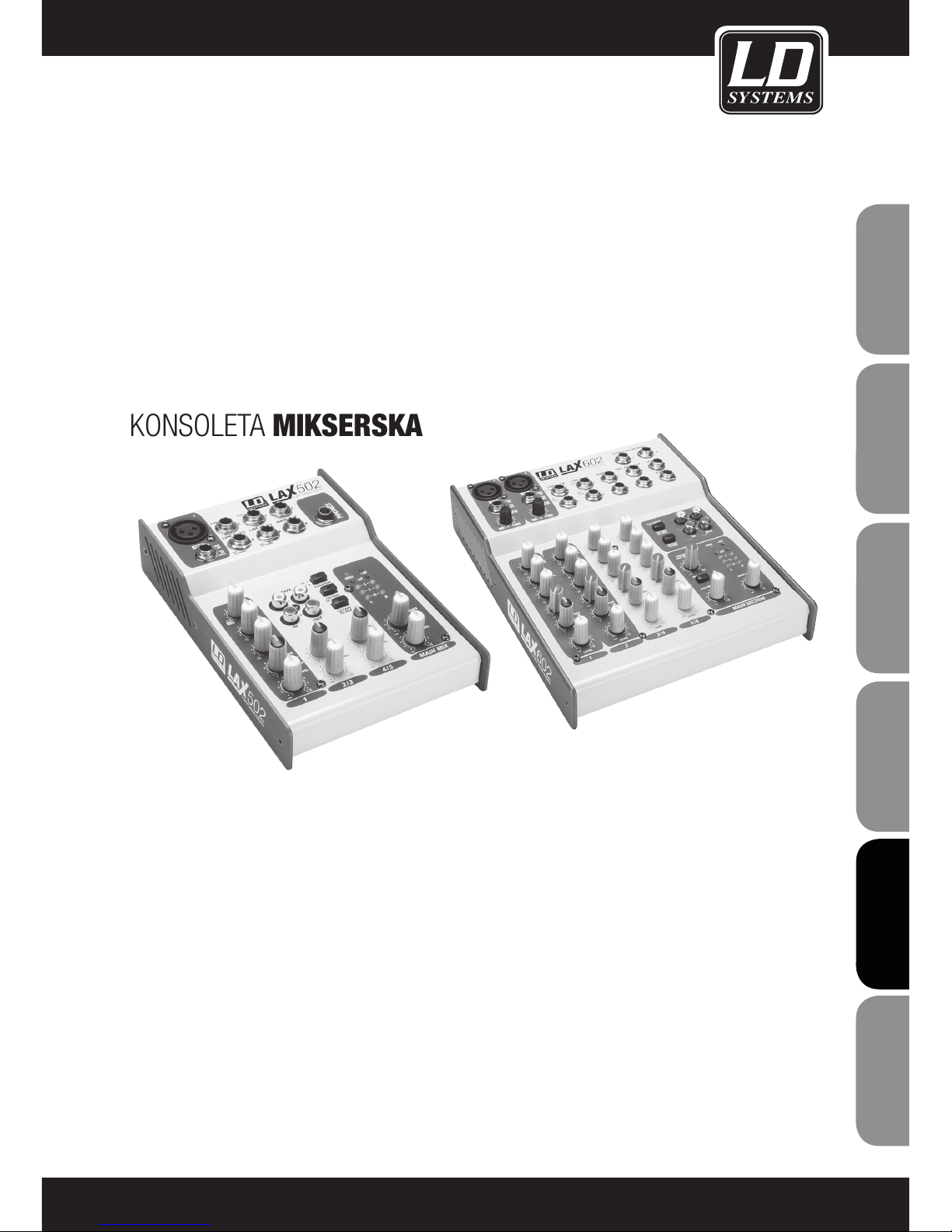
SERIA LD LAX
502 / 602
KONSOLETA MIKSERSKA
67
ITALIANO
POLSKI
ESPAÑOL
FRANCAIS
FRANCAIS
FRANCAIS
FRANCAIS
FRANCAIS
DEUTSCH
ENGLISH
Page 68
68
ENGLISHDEUTSCHFRANCAIS
FRANCAISFRANCAIS
FRANCAISFRANCAIS
ESPAÑOLPOLSKIITALIANO
1. Przeczytaj uważnie dołączone informacje na temat bezpieczeństwa i następujące po nich wskazówki.
2. Zachowaj pełną dokumentację produktu.
3. Używaj urządzenia zgodnie z jego przeznaczeniem.
4. Przestrzegaj przepisów dotyczących zarządzania odpadami. Posegreguj elementy opakowania na części z tworzywa
sztucznego i tektury przed ich przekazaniem do utylizacji.
5. Przekaż urządzenie wykwalifikowanym pracownikom serwisu, jeżeli zostało uszkodzone, narażone na kontakt z
deszczem lub płynami, lub gdy nie działa prawidłowo.
6. Nie przechowuj urządzenia w pobliżu źródeł ciepła takich jak piece, kaloryfery i inne urządzenia (w tym wzmacniacze).
Zawsze dbaj o zachowanie odległości między urządzeniem, a wzmacniaczami, ścianami, skrzyniami itd. aby zapobiec
przegrzaniu.
7. Po podłączeniu upewnij się, że wszystkie połączenia są wykonane prawidłowo, aby uniknąć jakiegokolwiek rodzaju
wypadku lub szkody.
Nigdy nie używaj wadliwego okablowania.
8. Używaj wyłącznie zatwierdzonych i stabilnych statywów, zaczepów, półek, stołów itp. przy instalacji. Po montażu
sprawdź stabilność konstrukcji.
9. Występowanie zakłóceń w systemach bezprzewodowych
Równoczesne używanie kilku mikrofonów bezprzewodowych (jeżeli są niezbyt oddalone od siebie) może prowadzić do
pojawienia się zakłóceń w sygnale mikrofonowym, które mogą być słyszalne w zestawie PA.
UWAGA:
Aby zmniejszyć zagrożenie porażeniem elektrycznym, nie zdejmuj pokrywy (lub tylnej części obudowy). Brak elementów
serwisowalnych przez użytkownika wewnątrz. Przekaż obsługę serwisową wykwalifikowanym fachowcom.
Symbol błyskawicy wewnątrz trójkąta równobocznego ostrzega użytkownika o nieizolowanych częściach
pod niebezpiecznym napięciem wewnątrz obudowy produktu, które w znaczący sposób zwiększają zagrożenie dla zdrowia i życia osób.
Znak wykrzyknika wewnątrz trójkąta równobocznego zwraca uwagę użytkownika na ważne wskazówki
odnośnie obsługi lub konserwacji (serwisu) umieszczone w instrukcjach i opisach dostarczonych wraz z
produktem.
OSTRZEŻENIE! WYSOKI POZIOM GŁOŚNOŚCI!
Opisywany system transmisyjny jest przeznaczony do zastosowań profesjonalnych. Dlatego też komercyjne użytkowanie
tego sprzętu podlega zasadom i przepisom bezpieczeństwa właściwym dla danego sektora działalności, w tym regulacjom określonym przez towarzystwa ubezpieczeniowe. Firma Adam Hall, jako wytwórca, jest zobowiązany do formalnego
poinformowania o istnieniu potencjalnych zagrożeń zdrowia.
System może być źródłem fali dźwiękowej o ciśnieniu akustycznym rzędu 80dB. Zgodnie z obowiązującymi przepisami,
ucho ludzkie może być narażone w czasie dnia roboczego na działanie dźwięków o poziomie 85dB. Poziom ten, na
podstawie ekspertyz technicznych specjalistów od medycyny pracy, został przyjęty jako podstawa klasyfikacji hałasu.
Wyższy poziom dźwięku lub dłuższy czas narażenia mogą spowodować uszkodzenie słuchu. Przy wyższych poziomach
ciśnienia akustycznego czas narażenia powinien być skrócony, aby zapobiec uszkodzeniu słuchu. Poniżej opisano kilka
objawów mogących wskazywać na to, że byłeś zbyt długo narażony na działanie dźwięków o zbyt wysokim poziomie
ciśnienia akustycznego:
– Słyszysz dzwonienie lub gwizd w uszach,
– Odnosisz wrażenie, że nie słyszysz wysokich tonów.
ŚRODKI BEZPIECZEŃSTWA:
CAUTION
RISK OF ELECTRIC SHOCK
DO NOT OPEN
Page 69

WSTĘP:
Gratulacje! Dokonując zakupu urządzenia LAX 502/602 stali się Państwo posiadaczami konsolety mikserskiej
charakteryzującej się nadzwyczajną wielofunkcyjnością i jakością dźwięku, a jednocześnie kompaktowymi
wymiarami.
Przedwzmacniacze mikrofonowe mogą być opcjonalnie wyposażone w zasilanie fantomowe. Urządzenie jest
wyposażone w zbalansowane wejście liniowe oraz bogaty wybór efektów. Wyposażenie konsolet mikserskich z
serii LAX optymalnie sprawdza się w zastosowaniach estradowych i studyjnych. Zastosowanie w urządzeniach z
serii LAX najwyższej jakości obwodów elektrycznych umożliwia uzyskanie niezrównanego ciepłego, analogowego
brzmienia. Kanały mikrofonowe wyposażone są w przedwzmacniacze mikrofonowe LAX, które pod względem
jakości dźwięku i charakterystyki dynamicznej nie ustępują kosztownym przedwzmacniaczom zewnętrznym.
Oferują one następujące funkcje:
- Zakres dynamiki wynoszący 130 dB daje ogromny zapas mocy.
- Szerokość pasma częstotliwości od 10 Hz od ponad 20 KHz umożliwia krystalicznie czystą reprodukcję nawet
najdrobniejszych detali.
- Dzięki zastosowaniu niskoszumowych i niepowodujących przesterowań układów elektrycznych możliwe jest
naturalne i przejrzyste odwzorowanie sygnału.
- Kanały te są idealnie dostosowane do każdego mikrofonu do 60dB wzmocnienia sygnału oraz zasilania
fantomowego +48V.
- Umożliwiają całkowite wykorzystanie rejestratora HD o paśmie dynamicznym 24bit / 192kHz, a co za tym
idzie, zachowanie optymalnej jakości dźwięku.
Zastosowane w serii LAX korektory częstotliwości zostały zbudowane w oparciu o układy elektryczne legendarnych brytyjskich konsolet mikserskich najwyższej klasy, charakteryzujących się niezwykle ciepłą i muzykalną
charakterystyką brzmieniową. Korekcja gwarantuje wysoką jakość dźwięku nawet przy znacznym wzmocnieniu
sygnału.
69
ITALIANO
POLSKI
ESPAÑOL
FRANCAIS
FRANCAIS
FRANCAIS
FRANCAIS
FRANCAIS
DEUTSCH
ENGLISH
Page 70
FUNKCJE / TRYBY PRACY:
PODSTAWOWE FUNKCJE KONSOLETY MIKSERSKIEJ
Konsoleta mikserska spełnia trzy zasadnicze zadania:
- Przetwarzanie sygnału: Wzmocnienie sygnału, dostosowanie poziomów sygnału, miksowanie efektów. Korekcja
częstotliwości
- Rozprowadzanie sygnału: Sumowanie sygnałów przesyłanych do wyjść dodatkowych do wykorzystania
zewnętrznych efektów lub monitorowania sygnału, przekazywanie do jednego lub kilku rejestratorów ścieżek,
wzmacniaczy, wyjść monitorowych i dwuśladowych.
- Miksowanie: Ustawianie poziomu głośności, zakresu częstotliwości i układu poszczególnych sygnałów w polu
stereofonicznym, kontrola poziomu sygnału zmiksowanego z uwzględnieniem urządzeń rejestrujących, przetwornic czy wzmacniaczy. Pozostałe zastosowanie miksera można zawrzeć w wyżej wymienionych funkcjach.
DZIAŁANIA WSTĘPNE
Należy zapewnić dostateczną ilość wolnej przestrzeni, aby umożliwić chłodzenie urządzenia. Nie wolno ustawiać
konsolety na urządzeniach wytwarzających wysokie temperatury, takich jak grzejniki czy wzmacniacze, aby
zapobiec przegrzaniu. Do podłączania urządzenia do sieci elektrycznej służy kabel dostarczony przez producenta.
Urządzenie spełnia obowiązujące normy bezpieczeństwa.
- Nigdy nie podłączać konsolety LAX do zasilacza uprzednio podłączonego do sieci elektrycznej! Najpierw
podłączyć konsoletę do zasilacza, następnie zasilacz do sieci elektrycznej.
- Należy pamiętać o prawidłowym uziemieniu urządzeń. Ze względów bezpieczeństwa nie należy demontować
połączeń uziemiających urządzeń i przewodów elektrycznych lub uniemożliwiać ich stosowanie.
- Montaż i użytkowanie urządzenia należy powierzyć osobom o odpowiednich kwalifikacjach..
70
ENGLISHDEUTSCHFRANCAIS
FRANCAISFRANCAIS
FRANCAISFRANCAIS
ESPAÑOLPOLSKIITALIANO
Page 71
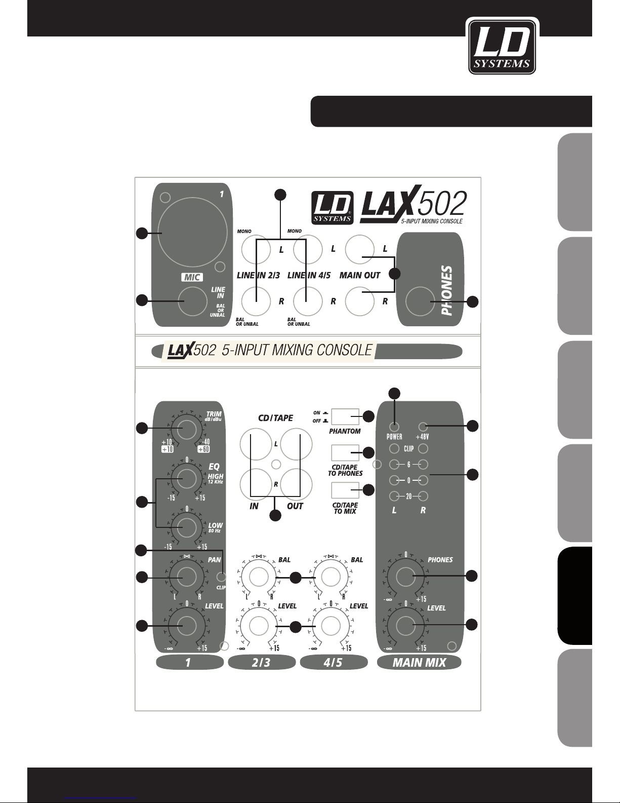
ELEMENTY STEROWANIA:
71
ITALIANO
POLSKI
ESPAÑOL
FRANCAIS
FRANCAIS
FRANCAIS
FRANCAIS
FRANCAIS
DEUTSCH
ENGLISH
1
2
3
4
5
6
7
8
9
10
11
12
13
14
15
16
18
19
20
21
17
Page 72
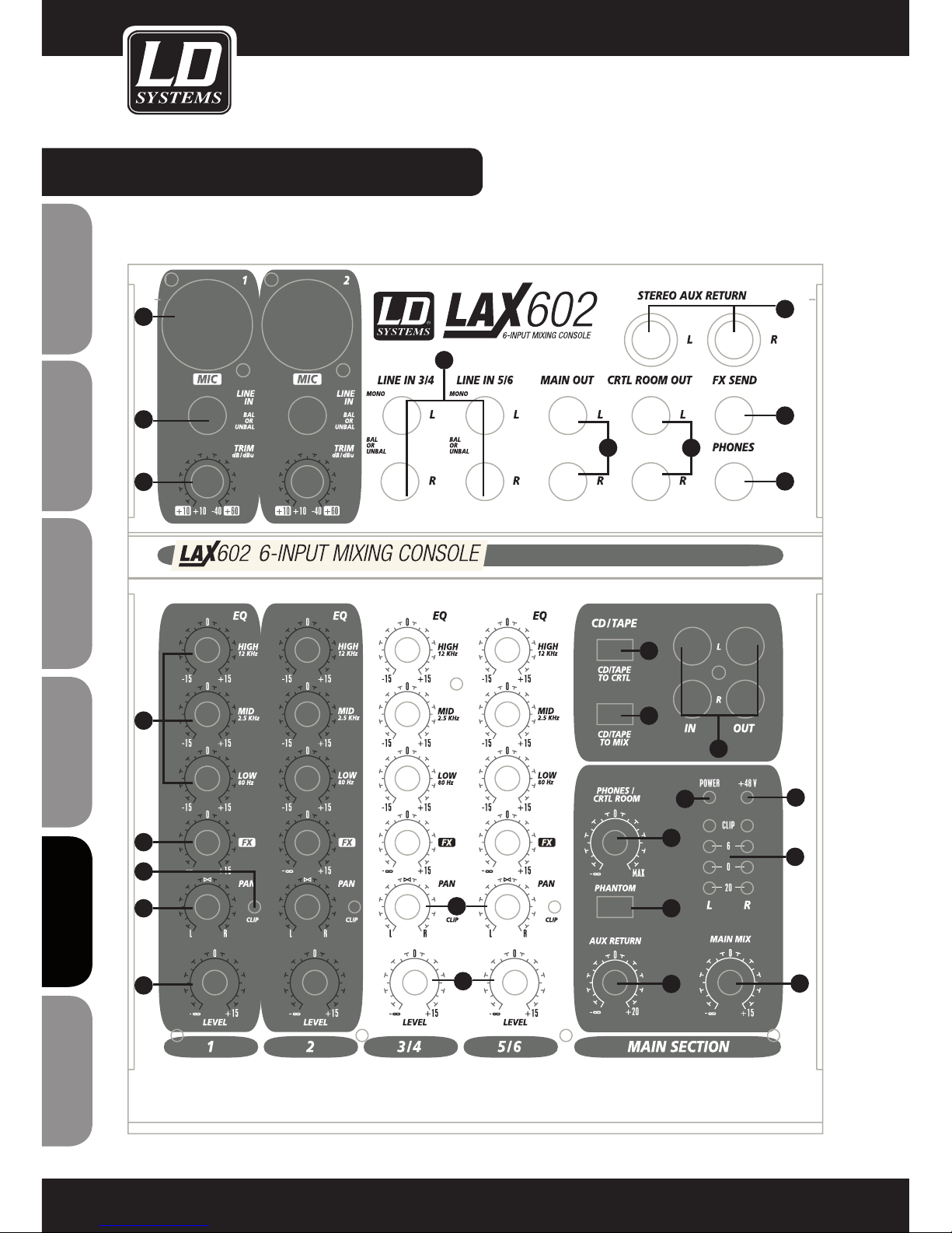
ELEMENTY STEROWANIA:
72
ENGLISHDEUTSCHFRANCAIS
FRANCAISFRANCAIS
FRANCAISFRANCAIS
ESPAÑOLPOLSKIITALIANO
1
2
3
4
5
6
7
8
9
10
11
12
13
14
15
16
18
19
20
21
17
22
23
26
24
25
Page 73
ELEMENTY STEROWANIA:
1
MIC
Każdy monofoniczny kanał wejściowy oferuje wejście zbalansowane XLR oraz odłączane zasilanie fantomowe +48V do mikrofonów pojemnościowych. Przedwzmacniacze mikrofonowe zastosowane w serii LAX
umożliwiają bezszumowe wzmacnianie sygnału charakterystyczne dla kosztownych przedwzmacniaczy
zewnętrznych.
2
LINE IN
Każde wejście mono jest wyposażone w zbalansowane wejście liniowe z gniazdem typu jack 6,3mm.
Urządzenia wyposażone w niezbalansowane wtyki mono także są obsługiwane.
3
TRIM
Regulator TRIM służy do ustawienia poziomu wzmocnienia sygnału wejściowego. Regulator powinien być
przesunięty jak najbardziej w lewo przy podłączaniu lub odłączaniu źródeł sygnału do wejść.
Skala posiada 2 zakresy wartości. Pierwsza (+10 do +60 dB) dotyczy wejścia mikrofonowego i określa
poziom wzmocnienia podawanego sygnału.
Zakres drugi (+10 do -40 dB) dotyczy wejścia liniowego i określa jego czułość
4
EQ
Wszystkie wejścia mono są wyposażone w trzypasmowy korektor (dwupasmowy w modelu LAX 502).
Wszystkie pasma umożliwiają wzmocnienie lub redukcję sygnału o maksymalnie 15 dB. W pozycji środkowej
korektor jest nieaktywny.
5
PAN
Regulator PAN określa pozycję danego kanału w obrazie stereo.
6
LEVEL
Regulator LEVEL określa poziom sygnału danego kanału w głównym miksie.
- Uwaga: Sygnał jest przesyłany do szyny efektów FX za tłumikiem, dlatego regulator LEVEL danego kanału
musi być odkręcony, aby sygnał został przesłany do procesora efektów. (NIE DOTYCZY MODELU LAX 502)
7
CLIP
Dioda CLIP zapala się, gdy poziom wejściowy sygnału monofonicznego jest nadmiernie wysoki, co mogłoby
doprowadzić do przesterowania. W takiej sytuacji można wykorzystać regulator poziomu przedwzmacniacza
TRIM do ograniczenia siły sygnału.
8
LINE IN
Każdy kanał stereofoniczny posiada dwa zbalansowane wejścia liniowe ze złączami jack 6,3mm dla lewego
i prawego kanału. Do pracy w trybie mono stosuje się kanał oznaczony „L” (lewy). Kanały stereofoniczne
obsługują typowe, liniowe sygnały wejściowe. Oba wejścia są kompatybilne ze złączami niezbalansowanymi.
73
ITALIANO
POLSKI
ESPAÑOL
FRANCAIS
FRANCAIS
FRANCAIS
FRANCAIS
FRANCAIS
DEUTSCH
ENGLISH
Page 74
ELEMENTY STEROWANIA:
9
BAL
Regulator balansu określa wzajemną proporcję poziomu sygnału kanału lewego i prawego przed przekierowaniem go do szyn głównego miksu stereo. Jeżeli kanał jest wykorzystywany w trybie mono, regulator pełni tę
samą funkcję, co regulator PAN kanału monofonicznego.
10
LEVEL
Regulator LEVEL określa poziom sygnału danego kanału w głównym miksie.
11
MAIN OUT
Złącza MAIN OUT to monofoniczne niezbalansowane złącza wyjściowe.
12
CD / TAPE
INPUT
Wejścia CD/MP3/TAPE INPUT służą do podłączania do konsolety zewnętrznych źródeł sygnału (np. odtwarzacza CD, magnetofonu). Mogą być one wykorzystywane jako standardowe stereofoniczne wejścia liniowe,
tak jak wyjścia drugiego miksera LAX.
OUTPUT
Złącza RCA połączone równolegle z wyjściem głównym MAIN OUT. To miejsce podłączenia wejść karty
dźwiękowej komputera lub rejestratora. Poziom sygnału wyjściowego jest regulowany za pomocą tłumika
MAIN MIX.
13
PHONES
Stereofoniczne gniazdo słuchawek typu jack 6,3 mm.
14
POZIOM PHONES
POZIOM CONTROL ROOM (POZA MODELEM LAX 502)
Regulatory PHONES / CONTROL ROOM służą do regulacji poziomu sygnału na wyjściu PHONES / CONTROL
ROOM.
15
POZIOM MAIN MIX
Regulator MAIN MIX służy do zmiany poziomu sygnału na wyjściu miksu głównego MAIN MIX.
16
ZASILANIE PHANTOM POWER
Przełącznik zasilania PHANTOM POWER służy do włączania i wyłączania zasilania fantomowego niezbędnego
do obsługi mikrofonów pojemnościowych (dostępne tylko dla wejścia mikrofonowego XLR)
17
DIODA +48V PHANTOM POWER
Dioda +48 V świeci się, jeśli zasilanie fantomowe jest włączone.
- Uwaga! Nie wolno stosować niezbalansowanych złączy XLR (PINY 1 i 3 połączone) do wejścia MIC z aktywnym zasilaniem fantomowym.
74
ENGLISHDEUTSCHFRANCAIS
FRANCAISFRANCAIS
FRANCAISFRANCAIS
ESPAÑOLPOLSKIITALIANO
Page 75
ELEMENTY STEROWANIA:
- Nie wolno podłączać mikrofonów do miksera (albo stageboxu/wallboxu) przy włączonym zasilaniu typu
fantomowym. Mikrofony należy podłączyć przed włączeniem zasilania. Dodatkowo należy wyciszyć monitory
odsłuchowe oraz kolumny nagłośnieniowe przed włączeniem zasilania. Po włączeniu zasilania należy odczekać
około 1 minuty na ustabilizowanie się systemu.
18
CD/TAPE TO PHONES
CD/TAPE TO CONTROL ROOM (POZA MODELEM LAX 502)
Przełącznik CD/TAPE TO PHONES / CONTROL ROOM umożliwia włączenie monitorowania wejścia
dwuśladowego przez wyjście słuchawkowe PHONES OUTPUT lub wyjście dodatkowe CONTROL ROOM
OUTPUT.
19
CD/TAPE TO MIX
Przełącznik CD/TAPE TO MIX umożliwia włączenie monitorowania wejścia dwuśladowego przez wyjście MIX
OUTPUT.
20
Dioda zasilania POWER
Świeci się po włączeniu urządzenia.
21
DIODY SIGNAL ORAZ CLIP
Czterosegmentowy wskaźnik informuje o poziomie sygnału. Dioda CLIP zapala się, gdy poziom wyjściowy
sygnału jest nadmiernie wysoki, co mogłoby doprowadzić do przesterowania. W takiej sytuacji można
wykorzystać regulator poziomu MAIN LEVEL do zredukowania głównego poziomu sygnału, aż do momentu,
gdy dioda zgaśnie.
22
FX
Działanie regulatora FX SEND w przypadku kanałów stereo i kanałów mono jest podobne. Ze względu na fakt,
że szyny efektów FX są monofoniczne, z wejścia stereo do szyny efektów FX jest przesyłana suma sygnału
stereo.
23
ZŁĄCZE FX SEND
Złącze FX SEND jest wyjściem sygnału wybranego spośród pojedynczych kanałów za pośrednictwem regulatorów FX SEND. To wejście służy do podłączenia zewnętrznego źródła efektów do przetwarzania sygnału
z głównej szyny efektów FX. Po stworzeniu miksu efektów sygnał może zostać przekierowany z wyjść
zewnętrznego źródła efektów do WEJŚCIA LINIOWEGO STEREO lub STEREOFONICZNEGO WEJŚCIA POMOCNICZEGO STEREO AUX RETURN (tylko w modelu LAX 602).
24
STEREO AUX RETURN (TYLKO MODEL LAX 602)
Złącza wejścia STEREO AUX RETURN służą do powrotnego wprowadzenia sygnału z zewnętrznych źródeł
efektów (do których sygnał dociera z dodatkowych wyjść konsolety) z powrotem do konsolety. Można także
wykorzystać złącza jako wejście stereo, ale w takim przypadku sygnał z zewnętrznego źródła efektów będzie
musiał zostać przekazany z powrotem do konsolety za pośrednictwem normalnego kanału stereo. Umożliwia
to jednak wykorzystanie korektora kanału na sygnale powracającym.
- Przy wykorzystywaniu kanału stereo jako wejścia powrotnego z zewnętrznego źródła efektów wbudowany
kontroler FX powinien zostać całkowicie wyłączony, aby zapobiec powstaniu sprzężenia.
75
ITALIANO
POLSKI
ESPAÑOL
FRANCAIS
FRANCAIS
FRANCAIS
FRANCAIS
FRANCAIS
DEUTSCH
ENGLISH
Page 76
ELEMENTY STEROWANIA:
25
REGULATOR STEREO AUX RETURN (TYLKO MODEL LAX 602)
Regulator AUX RETURN pozwoli ustawić poziom sygnału kanału efektów w miksie. Jeżeli wykorzystywany
jest tylko lewy kanał, regulator automatycznie przejdzie w tryb mono.
26
CONTROL ROOM OUT
Niezbalansowane wyjście CTRL ROOM OUT przesyła sumę sygnału efektów i miksu. Regulator PHONE/CONTROL ROOM służy do ustawiania poziomu sygnału na WYJŚCIACH słuchawkowym i CONTROL ROOM .
76
ENGLISHDEUTSCHFRANCAIS
FRANCAISFRANCAIS
FRANCAISFRANCAIS
ESPAÑOLPOLSKIITALIANO
Page 77
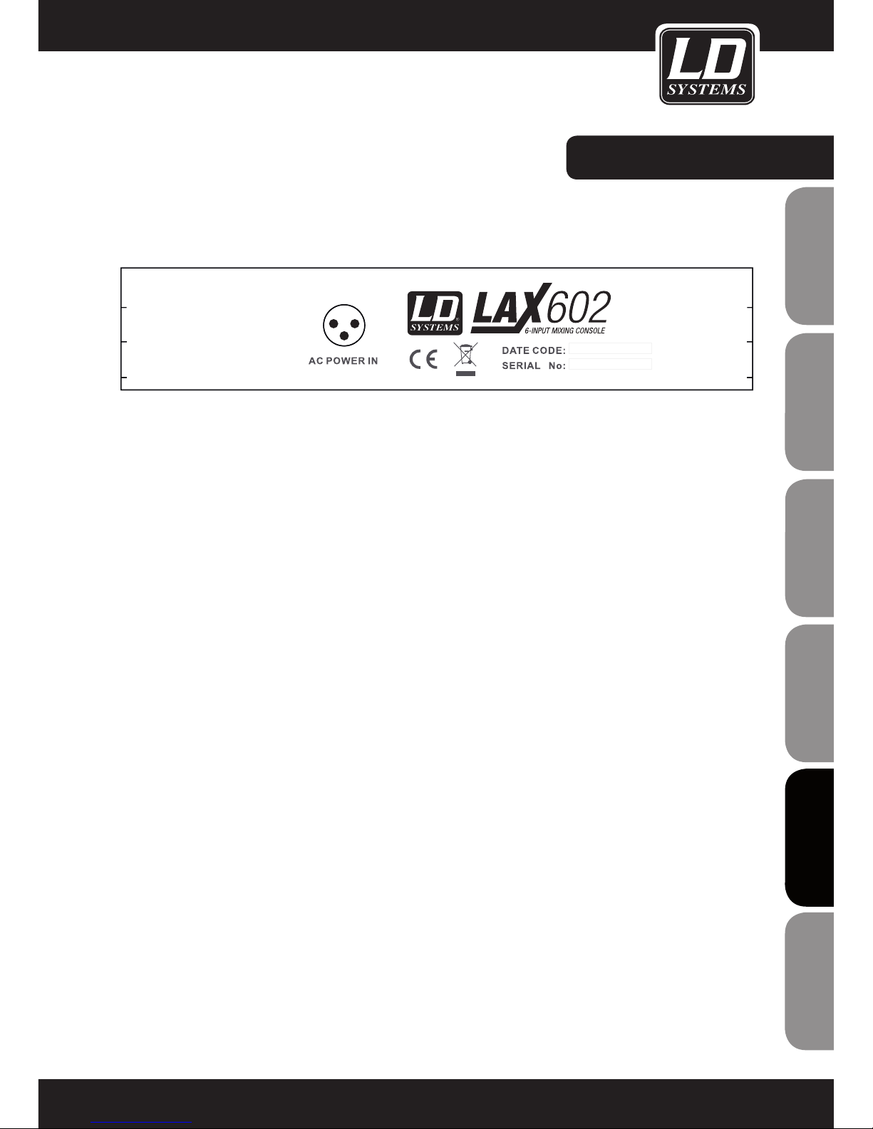
PANEL TYLNY:
GNIAZDO ZASILANIA
Przewód zasilacza należy podłączyć do 3-pinowego gniazda w tylnej części obudowy urządzenia. Urządzenie
należy podłączyć do sieci energetycznej za pośrednictwem dołączonego zasilacza. Zasilacz spełnia wszystkie
obowiązujące normy bezpieczeństwa.
- Należy korzystać wyłącznie z zasilacza dostarczonego wraz z urządzeniem.
- Nigdy nie podłączać miksera LAX do zasilacza uprzednio podłączonego do sieci elektrycznej! Najpierw
podłączyć konsoletę do zasilacza, następnie zasilacz do sieci energetycznej.
77
ITALIANO
POLSKI
ESPAÑOL
FRANCAIS
FRANCAIS
FRANCAIS
FRANCAIS
FRANCAIS
DEUTSCH
ENGLISH
Page 78
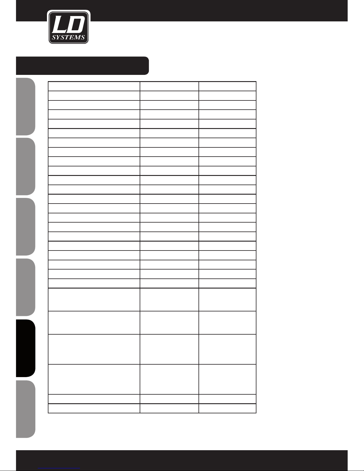
78
ENGLISHDEUTSCHFRANCAIS
FRANCAISFRANCAIS
FRANCAISFRANCAIS
ESPAÑOLPOLSKIITALIANO
DANE TECHNICZNE:
Model Name: LDLAX502 LAX602
Channels: 5 6
Mono Mic and Line Input Channels: 1 2
Mono Mic and Line Input Connectors: XLR, Jack 6,3 mm XLR, Jack 6,3 mm
Stereo Line Input Channels: 2 2
Stereo Line Input Connectors: Jack 6,3 mm mono Jack 6,3 mm mono
AUX / Effects Send Channels: 1
AUX / Effects Send Connectors: Jack 6,3 mm
Stereo AUX Return: 1
AUX Return Connectors: Jack 6,3 mm
Stereo Tape Out: 1 1
Stereo Tape Out Connectors: RCA RCA
Stereo Tape In: 1 1
Stereo Tape In Connenctors: RCA RCA
Stereo Main Out Unbalanced: 1 1
Stereo Main Out Unbalanced Connectors: Jack 6,3 mm Jack 6,3 mm
Stereo Control Room Out: 1
Stereo Control Room Out Connectors: Jack 6,3 mm
Headphones Out: 1 1
Headphones Out Connectors: Jack 6,3 mm Jack 6,3 mm
DFX: No No
Number of presets:
Controls Mono Mic and Line Input
Channels:
Gain, 2-Band EQ, Pan,
Channel Volume
Gain, 3-Band EQ, FX
Send, Pan, Channel
Volume
Controls Stereo Line Input Channels: Balance, Channel Volume 3-Band EQ, FX Send,
Balance, Channel
Volume
Controls Main Section: Phones Volume, Master
Volume, Tape to Phones,
Tape to Mix, Phantom
Power
Phones Volume, Master
Volume, Tape to Phones
/ Control Room, Tape to
Mix, Phantom Power
Indicators: Mono Channel Peak,
Power, 4 Segment Level
Meter, Phantom Power
Mono Channel Peak,
Stereo Channel Peak,
Power, 4 Segment Level
Meter, Phantom Power
Power Supply: external AC Adapter external AC Adapter
Dimensions (W x H x D): 125 x 45 x 195 mm 193 x 55 x 240 mm
Page 79

79
ITALIANO
POLSKI
ESPAÑOL
FRANCAIS
FRANCAIS
FRANCAIS
FRANCAIS
FRANCAIS
DEUTSCH
ENGLISH
DEKLARACJE PRODUCENTA:
GWARANCJA PRODUCENTA
Niniejsza gwarancja obejmuje zakupiony przez Państwa produkt Adam Hall marki LDSYSTEM. Niniejsza gwarancja nie
narusza ustawowych praw wynikających z rękojmi wobec sprzedawcy. Gwarancja ta określa dodatkowe oddzielne
roszczenia wobec firmy Adam Hall.
Udzielając niniejszej gwarancji, firma Adam Hall zapewnia, że zakupiony przez Państwa w firmie Adam Hall lub u
partnera firmy Adam Hall produkt przy normalnym użytkowaniu w okresie 2 lat od daty zakupu będzie wolny od wad
materiałowych lub wad technologicznych. Okres gwarancji rozpoczyna się z dniem zakupu. Potwierdzenie daty zakupu niezbędne dla dochodzenia roszczenia gwarancyjnego następuje poprzez okazanie paragonu opatrzonego datą
zakupu lub dowodu dostawy opatrzonego datą zakupu. Użytkownik ma prawo do serwisu gwarancyjnego zgodnie
z warunkami i postanowieniami wymienionymi w niniejszym dokumencie, jeśli wymagana jest naprawa w trakcie
okresu gwarancyjnego.
Niniejsza gwarancja przysługuje wyłącznie pierwotnemu kupującemu, który nabył produkt oferowany przez firmę
Adam Hall i nie podlega przeniesieniu na osoby, na które pierwotny kupujący przeniósł własność w odniesieniu do
produktu firmy Adam Hall.
W trakcie trwania okresu gwarancji wadliwe komponenty lub produkt firmy Adam Hall podlegają naprawie lub
wymianie. Wszystkie komponenty wymienione lub usunięte w ramach niniejszej gwarancji stają się własnością
firmy Adam Hall.
W mało prawdopodobnym przypadku, gdy w zakupionym przez Państwa produkcie firmy Adam Hall wada wystąpiłaby
wielokrotnie, firma Adam Hall może, według własnego uznania, zadecydować o wymianie tego produktu na porównywalny
produkt o co najmniej takich samych parametrach.
Firma Adam Hall nie udziela gwarancji na bezzakłóceniowe lub bezawaryjne działanie niniejszego produktu. Firma
Adam Hall nie ponosi odpowiedzialności za szkody wynikłe z nieprzestrzegania instrukcji objętych zakresem dostawy.
Niniejsza gwarancja nie obejmuje:
- części zużywalnych (np. akumulatora, lamp elektronowych);
- urządzeń, z których usunięto numer seryjny lub które zostały uszkodzone w wyniku wypadku;
- nieodpowiedniej lub nieprawidłowej eksploatacji lub innych przyczyn zewnętrznych;
- urządzeń, które były eksploatowane niezgodnie z parametrami pracy określonymi w dokumentacji użytkownika
objętej zakresem dostawy produktu;
- urządzeń, które były naprawiane przy użyciu części, których nie wyprodukowała lub nie sprzedała firma Adam Hall;
- urządzeń, które były serwisowane, modyfikowane lub naprawiane przez inne osoby niż firma Adam Hall lub jej
autoryzowany partner serwisowy.
Niniejsze postanowienia i warunki stanowią kompletną i wyłączną umowę gwarancyjną między klientem a firmą
Adam Hall dotyczącą zakupionego przez klienta produktu Adam Hall.
Niniejsza gwarancja jest ważna tylko na terenie Europy. Poza Europą proszę kontaktować się z naszymi oficjalnymi
dystrybutorami.
Page 80
80
ENGLISHDEUTSCHFRANCAIS
FRANCAISFRANCAIS
FRANCAISFRANCAIS
ESPAÑOLPOLSKIITALIANO
DEKLARACJE PRODUCENTA:
OGRANICZENIE ODPOWIEDZIALNOŚCI
Jeśli w produktach sprzętowych firmy Adam Hall w trakcie trwania okresu gwarancji wystąpią szkody
materiałowe lub technologiczne (zgodnie z powyższym oświadczeniem gwarancyjnym), jedyne i wyłączne
prawo klienta wynikające z niniejszej gwarancji dotyczy naprawy lub wymiany urządzenia. Maksymalna
odpowiedzialność firmy Adam Hall jest zgodnie z niniejszą gwarancją wyraźnie ograniczona do ceny kupna lub
kosztów naprawy lub wymiany (w zależności od tego, która z tych kwot będzie niższa) elementów uszkodzonych
podczas normalnego użytkowania.
Adam Hall nie ponosi odpowiedzialności za żadne szkody spowodowane przez produkt lub jego nieprawidłowe
działanie, włącznie z utraconym zyskiem i niepowstałymi oszczędnościami oraz szkodami szczególnymi,
pośrednimi i wynikowymi. Ponadto Adam Hall nie ponosi odpowiedzialności za roszczenia prawne osób trzecich
ani roszczenia zgłoszone przez klienta w imieniu osób trzecich.
Niniejsze ograniczenie odpowiedzialności obowiązuje niezależnie od tego, czy szkody są dochodzone na drodze
sądowej lub czy roszczenia odszkodowawcze wnoszone są w ramach niniejszej gwarancji w wyniku niedozwolonych działań (włącznie z niedbalstwem i odpowiedzialnością z tytułu zagrożenia) lub w wyniku roszczeń
umownych lub innych. Nie może ono zostać także przez nikogo zniesione ani zmienione. Niniejsze ograniczenie
odpowiedzialności obowiązuje także wówczas, gdy klient poinformuje firmę Adam Hall lub autoryzowanego
przedstawiciela firmy Adam Hall o możliwości wystąpienia takich szkód, nie obowiązuje natomiast w przypadku
roszczeń odszkodowawczych związanych ze szkodami na osobie.
Niniejsza gwarancja producenta przyznaje klientowi określone prawa. W zależności od jurysdykcji (państwo lub
kraj związkowy) klientowi może przysługiwać prawo zgłoszenia dalszych roszczeń. W takich przypadkach zaleca
się zastosowanie odpowiednich przepisów umożliwiających skorzystanie z pełni przysługujących danej osobie
praw.
SKORZYSTANIE Z GWARANCJI
W razie wystąpienia przypadku objętego gwarancją należy zwrócić się bezpośrednio do firmy Adam Hall lub do
autoryzowanego sprzedawcy, u którego produkt został zakupiony.
DEKLARACJA ZGODNOŚCI WE
Sprzedawane przez firmę Adam Hall urządzenia są zgodne z podstawowymi wymogami i pozostałymi
obowiązującymi specyfikacjami określonymi dyrektywami 1999/5/WE (R&TTE), 2004/108/WE (EMC) i 2006/95/
WE (LVD) (o ile mają zastosowanie). Dalsze informacje dostępne są na stronie www.adamhall.com.
Page 81
81
ITALIANO
POLSKI
ESPAÑOL
FRANCAIS
FRANCAIS
FRANCAIS
FRANCAIS
FRANCAIS
DEUTSCH
ENGLISH
DEKLARACJE PRODUCENTA:
PRAWIDŁOWA UTYLIZACJA NINIEJSZEGO PRODUKTU
(dotyczy Unii Europejskiej i innych krajów europejskich, w których stosuje się segregację odpadów)
Niniejszy symbol na produkcie lub związanych z nim dokumentach wskazuje, iż po zakończeniu okresu
użytkowania urządzenie nie może być utylizowane razem ze standardowymi odpadami domowymi, ponieważ
mogłoby to spowodować szkody w środowisku lub szkody na osobie powstałe w wyniku niekontrolowanego
usuwania odpadów. Niniejszy produkt należy utylizować oddzielnie od innych odpadów i przekazać do punktu
recyklingu w celu wspierania ruchu okrężnego w gospodarce w ramach idei zrównoważonego rozwoju.
Klienci prywatni otrzymują informacje w zakresie przyjaznych dla środowiska możliwości usuwania odpadów od
sprzedawcy, u którego produkt został zakupiony, lub w odpowiednich placówkach regionalnych.
Użytkownicy będący przedsiębiorcami proszeni są o kontakt ze swoimi dostawcami i ewentualne sprawdzenie
uzgodnionych umownie warunków utylizacji urządzeń. Niniejszy produkt nie może być utylizowany razem z
innymi odpadami przemysłowymi.
OCHRONA ŚRODOWISKA I OSZCZĘDZANIE ENERGII
Oszczędzanie energii stanowi aktywny wkład w ochronę środowiska. Należy wyłączać wszystkie nieużywane
urządzenia elektryczne. Aby zapobiec zużywaniu prądu przez nieużywane urządzenia znajdujące się w trybie
czuwania (standby), należy wyjąć wtyczkę z gniazda sieciowego.
Adam Hall GmbH, wszystkie prawa zastrzeżone. Dane techniczne i funkcjonalne produktu mogą podlegać
modyfikacjom. Kopiowanie, tłumaczenie i pozostałe formy reprodukcji fragmentów lub całości tej instrukcji
obsługi są zabronione.
Page 82

82
ENGLISHDEUTSCHFRANCAIS
FRANCAISFRANCAIS
FRANCAISFRANCAIS
ESPAÑOLPOLSKIITALIANO
Acquistando un prodotto LD Systems avete fatto la scelta giusta!
Quest'apparecchio è stato sviluppato e prodotto secondo elevati standard qualitativi che garantiscono un funzionamento regolare per molti anni. Per questo motivo LD Systems, con il suo nome e la pluriennale esperienza,
rappresenta un'azienda produttrice di prodotti audio di qualità.
Leggete attentamente questo manuale d'uso per utilizzare al meglio il vostro nuovo amplificatore LD Systems.
Per ulteriori informazioni sui prodotti LD Systems consultate il nostro sito internet WWW.LD-SYSTEMS.COM
Page 83
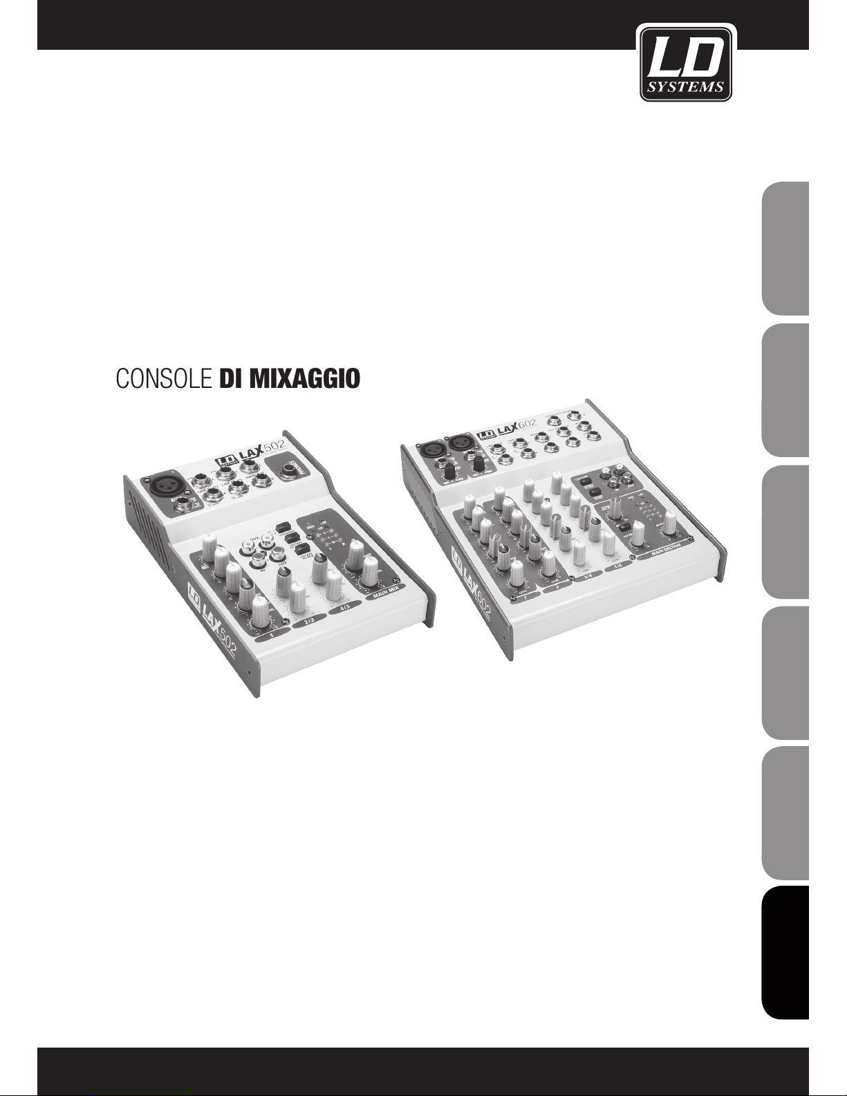
LD SERIE LAX
502 / 602
CONSOLE DI MIXAGGIO
83
ITALIANO
POLSKI
ESPAÑOL
FRANCAIS
FRANCAIS
FRANCAIS
FRANCAIS
FRANCAIS
DEUTSCH
ENGLISH
Page 84
84
ENGLISHDEUTSCHFRANCAIS
FRANCAISFRANCAIS
FRANCAISFRANCAIS
ESPAÑOLPOLSKIITALIANO
1. Attenersi alle avvertenze di sicurezza e leggere attentamente il presente manuale.
2. Conservare in un luogo sicuro tutte le avvertenze e le indicazioni.
3. Utilizzare l'apparecchio solo nei modi previsti dal manuale.
4. Rispettare le leggi in vigore nel paese di installazione sullo smaltimento. Separare la plastica dalla carta e
dal cartone per lo smaltimento.
5. Se l'apparecchio non funziona più correttamente, è stato esposto a liquidi o è stato in qualche modo
danneggiato, rivolgersi esclusivamente a personale autorizzato per le dovute riparazioni.
6. Tenere l'apparecchio lontano da fonti di calore come stufe, termosifoni o altro (anche amplificatori).
Controllare che l'apparecchio sia sempre posizionato in modo tale che si possa raffreddare e che non si
surriscaldi.
7. Controllare tutte le linee alle quali l'apparecchio è collegato per evitare danni o incidenti.
8 Utilizzare esclusivamente supporti stabili e adeguati per fissare l'apparecchio. Verificare che l'apparecchio
sia installato in modo stabile e non possa cadere.
ATTENZIONE:
Non togliere mai il coperchio di protezione: pericolo di scosse elettriche.
All'interno dell'apparecchio non ci sono parti che possono essere controllate o riparate dall'utente.
Per la riparazione rivolgersi esclusivamente a personale qualificato.
Questo simbolo avverte del pericolo dovuto alla presenza di una tensione pericolosa non isolata
all'interno dell'apparecchio che può causare scosse pericolose.
Questo simbolo indica avvertenze e istruzioni d'uso importanti.
Attenzione! Volume alto!
Questi sistemi di trasmissione vengono utilizzati dall'utente per scopi professionali. Pertanto l'uso per scopi
commerciali è soggetto alle norme e ai regolamenti delle associazioni di categoria competenti. Adam Hall,
in qualità di produttore, è perciò obbligato a segnalare espressamente la presenza di possibili rischi per la
salute.
Questi altoparlanti possono generare elevate pressioni sonore. 85db è la pressione sonora massima che per
legge può essere esercitata sull'udito umano in una giornata lavorativa. Questo valore è stato stabilito in
base a quanto rilevato nel campo della medicina del lavoro. Suoni di maggiore intensità o più prolungati possono provocare danni all'apparato uditivo. Nel caso di volumi più elevati sarà necessario diminuire il tempo
di esposizione per evitare eventuali danni all'udito. Alcuni campanelli di allarme che indicano una prolungata
esposizione a suoni troppo forti sono:
- La presenza di suoni o fischi all'interno dell'orecchio!
- La sensazione di non sentire più i suoni ad alta frequenza!
AVVERTENZE:
CAUTION
RISK OF ELECTRIC SHOCK
DO NOT OPEN
Page 85

INTRODUZIONE:
Congratulazioni! Con LAX 502/602 avete acquistato una console di mixaggio che nonostante le dimensioni
compatte è in grado di garantire versatilità e performance audio eccezionali.
Il sistema dispone di preamplificatori microfonici con alimentazione phantom opzionale. Inoltre è presente un
ingresso di linea bilanciato e una sezione effetti estremamente potente. Le console di mixaggio della serie LAX
sono ottimizzate per garantire performance di alto livello sia dal vivo che in studio. Grazie ad una circuiteria
all'avanguardia le console LAX sono in grado di restituire un suono analogico caldo che non ha rivali. I canali
microfonici dispongono di preamplificatori microfonici high-end LAX che reggono bene il confronto con preamplificatori esterni di fascia alta per quanto riguarda la qualità del suono e la dinamica. Le loro caratteristiche sono
le seguenti.
- Spettro dinamico di 130 dB che garantisce un headroom incredibile.
- Una larghezza di banda che si estende da meno 10 Hz fino ad arrivare a 20 KHz per una riproduzione impeccabile anche delle sfumature più sottili.
- La circuiteria estremamente silenziosa e senza distorsioni garantisce un riproduzione del segnale naturale e
trasparente.
- I mixer si adattano perfettamente a qualsiasi microfono con un guadagno fino a 60 dB e un'alimentazione
phantom a +48 volt.
- Inoltre permettono di sfruttare al meglio lo spettro dinamico estremamente ampio del registratore HDD da 24bit / 192 kHz, mantenendo allo stesso tempo una qualità audio ottimale.
Gli equalizzatori utilizzati nella serie LAX sono basati sulla circuiteria leggendaria delle straordinarie console
britanniche, rinomate in tutto il mondo perché in grado di restituire un suono incredibilmente caldo e musicale.
Questi equalizzatori sono infatti in grado di garantire una qualità del suono eccellente anche con impostazioni di
guadagno estreme.
85
ITALIANO
POLSKI
ESPAÑOL
FRANCAIS
FRANCAIS
FRANCAIS
FRANCAIS
FRANCAIS
DEUTSCH
ENGLISH
Page 86
FUNZIONI / USO:
FUNZIONI GENERALI DELLA CONSOLE DI MIXAGGIO
Una console di mixaggio svolge principalmente tre funzioni:
- elaborazione del segnale: preamplificazione, regolazione del livello, mixaggio di effetti. Equalizzazione della
frequenza.
- distribuzione del segnale: somma dei segnali verso le mandate aux per l'elaborazione di effetti e per il monitor
mix, distribuzione verso una o più tracce di registrazione, amplificatore/i di potenza, control room e uscite a due
tracce.
- Mixaggio: impostazione del volume, della distribuzione della frequenza e del posizionamento dei singoli segnali
nel campo stereo, controllo del livello del mixaggio totale per allinearlo ai dispositivi di registrazione, al crossover
e al/agli amplificatore/i di potenza. Tutte le altre funzioni di mixaggio possono essere incluse in questa funzione
generale.
OPERAZIONI PRELIMINARI
Assicurarsi che vi sia sufficiente spazio libero intorno all'unità in modo da garantirne il raffreddamento. Non posizionare la console di mixaggio in prossimità di dispositivi che raggiungono temperature elevate come radiatori
o amplificatori di potenza per evitare il surriscaldamento. Utilizzare il cavo fornito per collegare la console alla
rete. La console risponde agli standard di sicurezza richiesti.
- Non collegare mai LAX all'unità di alimentazione quando quest'ultima è già collegata alla rete elettrica. Collegare prima la console all'unità di alimentazione e successivamente quest'ultima alla rete elettrica.
- Assicurarsi che tutte le unità siano debitamente collegate a terra. Per motivi di sicurezza è vietato rimuovere
qualsiasi connettore di terra dai dispositivi elettrici o dai cavi di alimentazione o disattivarli.
-Assicurarsi che la console di mixaggio venga installata e utilizzata esclusivamente da personale qualificato.
86
ENGLISHDEUTSCHFRANCAIS
FRANCAISFRANCAIS
FRANCAISFRANCAIS
ESPAÑOLPOLSKIITALIANO
Page 87
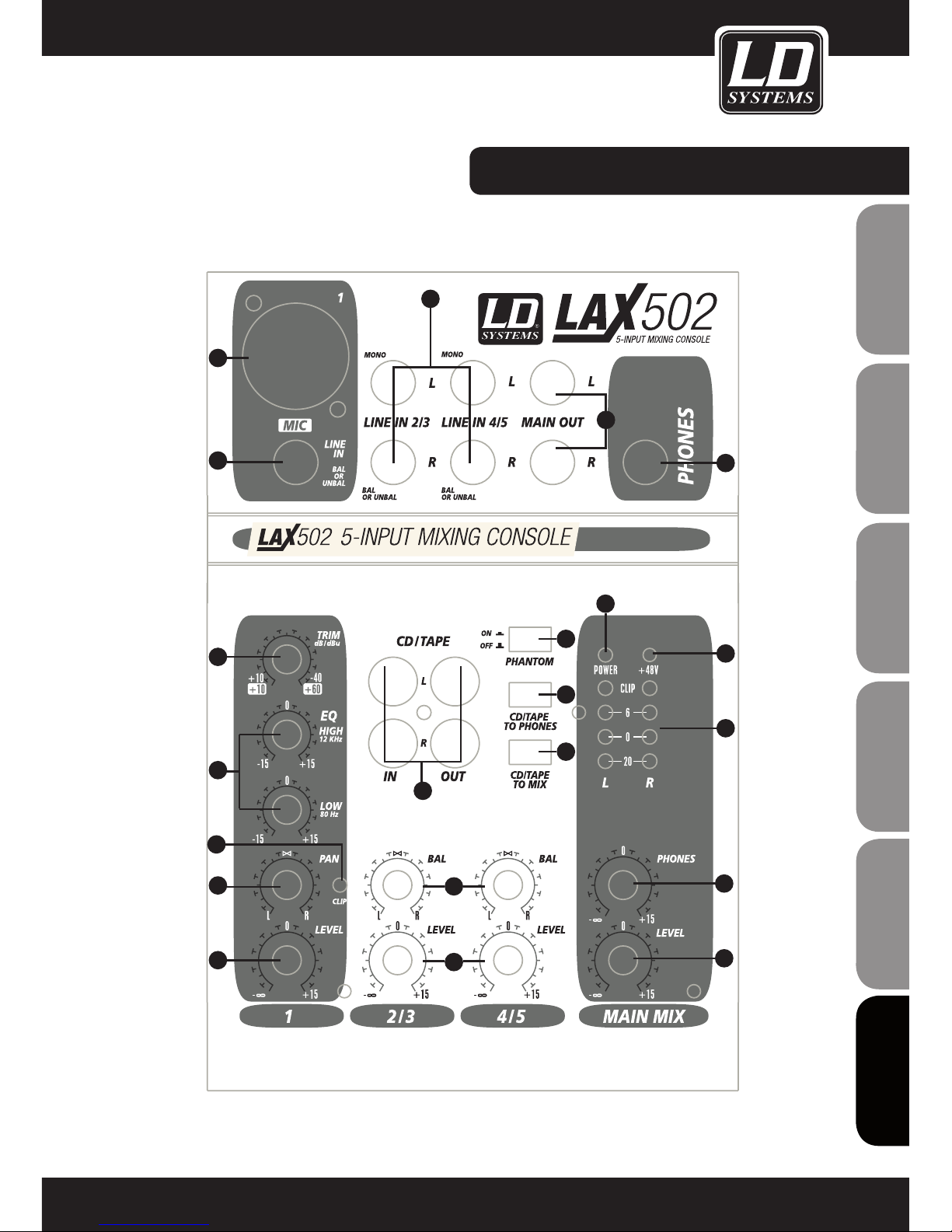
DISPOSITIVI DI COMANDO:
87
ITALIANO
POLSKI
ESPAÑOL
FRANCAIS
FRANCAIS
FRANCAIS
FRANCAIS
FRANCAIS
DEUTSCH
ENGLISH
1
2
3
4
5
6
7
8
9
10
11
12
13
14
15
16
18
19
20
21
17
Page 88
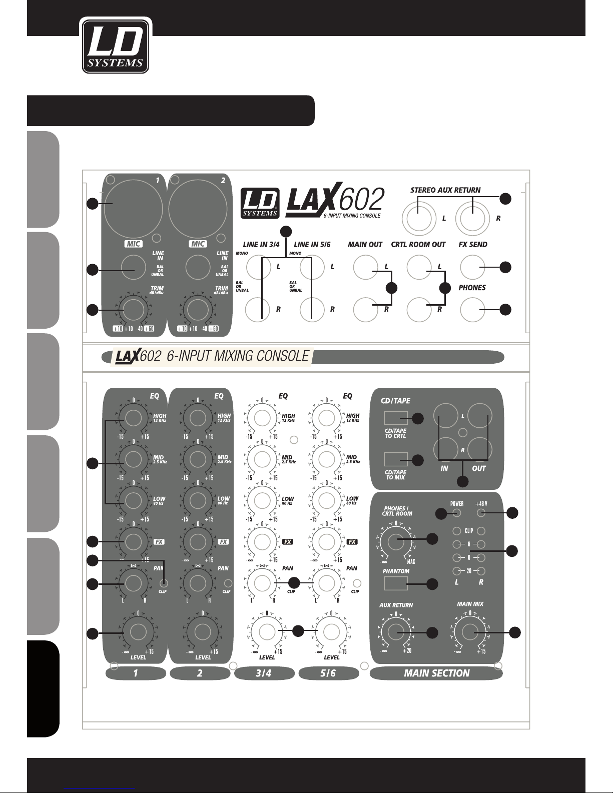
DISPOSITIVI DI COMANDO:
88
ENGLISHDEUTSCHFRANCAIS
FRANCAISFRANCAIS
FRANCAISFRANCAIS
ESPAÑOLPOLSKIITALIANO
1
2
3
4
5
6
7
8
9
10
11
12
13
14
15
16
18
19
20
21
17
22
23
26
24
25
Page 89
DISPOSITIVI DI COMANDO:
1
MIC
Ogni canale di ingresso mono è dotato di un ingresso microfonico bilanciato tramite un connettore XLR nonché di un’alimentazione phantom +48 V selezionabile per microfoni a condensatore. I preamplificatori LAX
offrono un guadagno privo di fruscii e distorsioni solitamente garantito soltanto da preamplificatori esterni di
alta fascia.
2
LINE IN
Ogni ingresso mono è dotato inoltre di un ingresso di linea bilanciato tramite connettore jack da 6,3 mm. A
questi ingressi è possibile collegare anche dispositivi sbilanciati (jack mono).
3
TRIM
Utilizzare il controllo TRIM per regolare il guadagno in ingresso. Ogni volta che si collega o si scollega una
fonte di segnale ad uno degli ingressi ruotare questa manopola completamente verso sinistra.
Sul controllo sono presenti due scale di valori: la prima scala (da +10 a +60 dB) si riferisce all’ingresso MIC
e mostra il livello di amplificazione del relativo segnale in ingresso, mentre la seconda scala (da +10 a -40
dB) si riferisce all’ingresso di linea e indica la sua sensibilità.
4
EQ
Tutti i canali di ingresso mono sono dotati di un equalizzatore a tre bande (equalizzatore a due bande per LAX
502). Ogni banda permette di regolare il taglio e l’enfasi fino a 15 dB. Quando si trova in posizione centrale
l’equalizzatore è disattivato.
5
PAN
Il controllo PAN determina la posizione del segnale del canale all’interno dell’immagine stereo.
6
LEVEL
Il controllo LEVEL determina il livello del segnale del canale nel main mix.
- Attenzione: il percorso FX del processore di effetti è collegato post fader quindi il controllo LEVEL deve essere attivato per consentire al segnale del canale di raggiungere il processore di effetti. (escluso LAX 502)
7
CLIP
Il led del CLIP sui canali mono si illumina quando il segnale di ingresso è troppo elevato e potrebbe causare
delle distorsioni. Quando il led si illumina, utilizzare il controllo TRIM per ridurre il livello del preamplificatore
fino a quando il led non si spegne.
8
LINE IN
Ogni canale stereo è dotato di due ingressi di livello linea bilanciati attraverso connettori jack da 6,3 mm per
i canali di destra e di sinistra. Se si utilizza soltanto il connettore "L" (sinistro), il canale viene attivato in modalità mono. I canali stereo sono progettati per gestire segnali di livello linea standard. Entrambi gli ingressi
permettono anche il collegamento di connettori sbilanciati.
89
ITALIANO
POLSKI
ESPAÑOL
FRANCAIS
FRANCAIS
FRANCAIS
FRANCAIS
FRANCAIS
DEUTSCH
ENGLISH
Page 90
DISPOSITIVI DI COMANDO:
9
BAL
Il controllo del bilanciamento server a bilanciare il livello dei segnali di ingresso sinistro e destro prima che
entrambi vengano inviati al bus di mixaggio del main stereo. Se sull'ingresso di linea il canale funziona in
modalità mono, questo controllo ha la stessa funzione del controllo PAN utilizzato nei canali mono.
10
LEVEL
Il controllo LEVEL determina il livello del segnale del canale nel main mix.
11
MAIN OUT
I connettori MAIN OUT sono connettori mono sbilanciati.
12
CD / TAPE
INGRESSI
Gli ingressi CD/MP3/TAPE sono utilizzati per collegare una sorgente di segnale esterna (ad es. lettore CD,
cassette, etc.) alla console. Questi ingressi possono essere utilizzati anche come ingressi di linea stereo
standard, quindi come uscite di un secondo mixer LAX.
USCITE
Questi connettori RCA sono collegati in parallelo ai connettori MAIN OUT. A questi connettori è possibile collegare l'ingresso di una scheda audio di un computer o l'ingresso di un registratore. Il livello del segnale di
uscita viene poi regolato utilizzando il fader MAIN MIX ad alta precisione.
13
PHONES
Jack stereo da 6,3 mm per cuffie.
14
LIVELLO PHONES
LIVELLO CONTROL ROOM (escluso LAX 502)
Utilizzare il controllo del livello PHONES / CONTROL ROOM per regolare il livello del segnale sulle uscite
PHONES / CONTROL ROOM.
15
LIVELLO MAIN MIX
Utilizzare il controllo del livello MAIN MIX per regolare il livello del segnale sulle uscite MAIN MIX.
16
PHANTOM POWER
L'alimentazione phantom è necessaria per utilizzare i microfoni a condensatore e può essere attivata tramite
l'interruttore PHANTOM POWER. (disponibile solo con ingressi mic XLR)
17
LED ALIMENTAZIONE PHANTOM +48V
Il led +48 V si illumina quando è attiva l'alimentazione phantom.
- Attenzione! Non utilizzare connettori XLR sbilanciati (PIN da 1 a 3 collegati) sui connettori di ingresso MIC
se si intende utilizzare l'alimentazione phantom.
90
ENGLISHDEUTSCHFRANCAIS
FRANCAISFRANCAIS
FRANCAISFRANCAIS
ESPAÑOLPOLSKIITALIANO
Page 91
DISPOSITIVI DI COMANDO:
- Non collegare i microfoni al mixer (o allo stagebox / armadio rack) fin quando l'alimentazione phantom è attiva.
Collegare i microfoni prima di collegare il dispositivo alla rete. Inoltre è necessario disattivare gli altoparlanti PA e
monitor prima di attivare l'alimentazione phantom. Dopo l'accensione attendere circa un minuto per permettere la
stabilizzazione del sistema.
18
CD/TAPE TO PHONES
CD/TAPE TO CONTROL ROOM (escluso LAX 502)
Premere il pulsante CD/TAPE TO PHONES / CONTROL ROOM per monitorare l'ingresso a due traccie tramite
l'uscita PHONES e l'uscita CONTROL ROOM.
19
CD/TAPE TO MIX
Premere il pulsante CD/TAPE TO MIX per monitorare l'ingresso a due traccie tramite l'uscita MIX.
20
LED ALIMENTAZIONE
Il led si illumina quando il mixer è acceso.
21
LED DEL SEGNALE E DI CLIP
L’indicatore di livello a 4 segmenti permette di visualizzare il livello del segnale. Il led del CLIP si illumina
quando il segnale di uscita è troppo elevato e potrebbe causare delle distorsioni. Quando il led si illumina
utilizzare il controllo MAIN LEVEL per ridurre il livello generale fino a quando il led non si spegne.
22
FX
I controlli FX SEND dei canali stereo funzionano in modo simile ai controlli dei canali mono. Tuttavia, dal
momento che i bus di mandata FX sono entrambi mono, i segnali provenienti dall’ingresso stereo dovranno
essere sommati in mono prima di essere inviati al bus FX.
23
CONNETTORE FX SEND
Il connettore FX SEND permette l’uscita del segnale scelto per ogni singolo canale utilizzando i controlli FX
SEND. Questo segnale può essere collegato all’ingresso di un processore di effetti esterno per elaborare il
segnale master del bus FX. Una volta creato l’effetto desiderato, il segnale può essere trasferito nuovamente
dal processore di effetti al mixer attraverso un INGRESSO DI LINEA STEREO o attraverso l’ingresso STEREO
AUX RETURN (solo LAX 602).
24
STEREO AUX RETURN (solo LAX 602)
I connettori STEREO AUX RETURN sono utilizzati per importare nuovamente il segnale di uscita proveniente
dal processore di effetti (il cui ingresso proviene dalle mandate aux) all’interno della console. Questi connettori possono essere utilizzati anche come ingressi supplementari, ma in questo caso il segnale proveniente da
un processore di effetti dovrà essere reimportato nella console attraverso un normale canale stereo. Questa
soluzione permette però di utilizzare l’equalizzatore del canale sul segnale di ritorno degli effetti se necessario.
- Nel caso in cui il percorso di ritorno degli effetti sia un canale stereo, il controllo FX dovrà essere impostato
al minimo per evitare sgradevoli rumori di ritorno.
91
ITALIANO
POLSKI
ESPAÑOL
FRANCAIS
FRANCAIS
FRANCAIS
FRANCAIS
FRANCAIS
DEUTSCH
ENGLISH
Page 92
DISPOSITIVI DI COMANDO:
25
CONTROLLO STEREO AUX RETURN (solo LAX 602)
Utilizzare il controllo AUX RETURN per determinare il livello del segnale degli effetti che viene inviato al main
mix. Nel caso in cui venga utilizzato soltanto il connettore sinistro, il controllo AUX RETURN funziona automaticamente in modalità mono.
26
CONTROL ROOM OUT
Il connettore sbilanciato CTRL ROOM OUT trasporta i segnali degli effetti sommati e del main mix. Il controllo
PHONE/CONTROL ROOM permette di regolare il livello sia delle cuffie sia delle USCITE CONTROL ROOM.
92
ENGLISHDEUTSCHFRANCAIS
FRANCAISFRANCAIS
FRANCAISFRANCAIS
ESPAÑOLPOLSKIITALIANO
Page 93
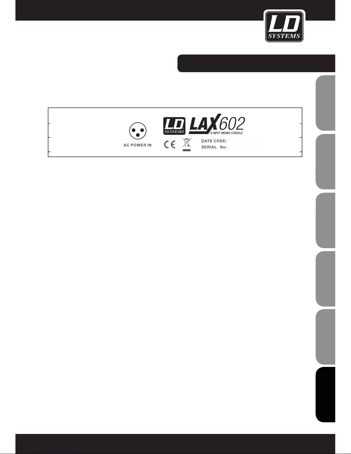
PANNELLO POSTERIORE:
CONNETTORE DI ALIMENTAZIONE AC
Utilizzare il connettore di rete tripolare posto sul pannello posteriore fornire alimentazione alla console. Utilizzare
l'adattatore AC fornito per collegare la console alla rete. L'adattatore è conforme a tutti gli standard di sicurezza
applicabili.
- Utilizzare esclusivamente l'unità di alimentazione fornita insieme alla console.
- Non collegare mai il mixer LAX all'unità di alimentazione quando quest'ultima è già collegata alla rete elettrica.
Collegare prima la console all'unità di alimentazione e successivamente quest'ultima alla rete elettrica.
93
ITALIANO
POLSKI
ESPAÑOL
FRANCAIS
FRANCAIS
FRANCAIS
FRANCAIS
FRANCAIS
DEUTSCH
ENGLISH
Page 94
94
ENGLISHDEUTSCHFRANCAIS
FRANCAISFRANCAIS
FRANCAISFRANCAIS
ESPAÑOLPOLSKIITALIANO
DATI TECNICI:
Model Name: LDLAX502 LAX602
Channels: 5 6
Mono Mic and Line Input Channels: 1 2
Mono Mic and Line Input Connectors: XLR, Jack 6,3 mm XLR, Jack 6,3 mm
Stereo Line Input Channels: 2 2
Stereo Line Input Connectors: Jack 6,3 mm mono Jack 6,3 mm mono
AUX / Effects Send Channels: 1
AUX / Effects Send Connectors: Jack 6,3 mm
Stereo AUX Return: 1
AUX Return Connectors: Jack 6,3 mm
Stereo Tape Out: 1 1
Stereo Tape Out Connectors: RCA RCA
Stereo Tape In: 1 1
Stereo Tape In Connenctors: RCA RCA
Stereo Main Out Unbalanced: 1 1
Stereo Main Out Unbalanced Connectors: Jack 6,3 mm Jack 6,3 mm
Stereo Control Room Out: 1
Stereo Control Room Out Connectors: Jack 6,3 mm
Headphones Out: 1 1
Headphones Out Connectors: Jack 6,3 mm Jack 6,3 mm
DFX: No No
Number of presets:
Controls Mono Mic and Line Input
Channels:
Gain, 2-Band EQ, Pan,
Channel Volume
Gain, 3-Band EQ, FX
Send, Pan, Channel
Volume
Controls Stereo Line Input Channels: Balance, Channel Volume 3-Band EQ, FX Send,
Balance, Channel
Volume
Controls Main Section: Phones Volume, Master
Volume, Tape to Phones,
Tape to Mix, Phantom
Power
Phones Volume, Master
Volume, Tape to Phones
/ Control Room, Tape to
Mix, Phantom Power
Indicators: Mono Channel Peak,
Power, 4 Segment Level
Meter, Phantom Power
Mono Channel Peak,
Stereo Channel Peak,
Power, 4 Segment Level
Meter, Phantom Power
Power Supply: external AC Adapter external AC Adapter
Dimensions (W x H x D): 125 x 45 x 195 mm 193 x 55 x 240 mm
Page 95

95
ITALIANO
POLSKI
ESPAÑOL
FRANCAIS
FRANCAIS
FRANCAIS
FRANCAIS
FRANCAIS
DEUTSCH
ENGLISH
DICHIARAZIONI DEL PRODUTTORE:
GARANZIA DEL PRODUTTORE
Questa garanzia copre il prodotto Adam Hall della marca LDSYSTEMS da Lei acquistato. I diritti legali di garanzia
verso il venditore non sono oggetto della presente garanzia. Questa garanzia costituisce piuttosto la base di altri
diritti verso Adam Hall.
Con la presente garanzia, Adam Hall assicura che il prodotto acquistato presso Adam Hall o un partner di Adam
Hall, in normali condizioni d‘uso resterà privo di difetti di materiale e di lavorazione per un periodo di 2 anni dalla
data di acquisto. Il periodo di garanzia inizia con la data dell‘acquisto. La certificazione della data di acquisto,
necessaria a rendere valido il diritto ai servizi di garanzia, avviene attraverso lo scontrino oppure con la bolla di
spedizione riportanti la data di acquisto. L‘acquirente ha diritto al servizio di garanzia alle condizioni e secondo
le disposizioni riportate in questo documento, qualora sia necessaria una riparazione durante il periodo di durata
della garanzia.
Questa garanzia vale solo per l‘acquirente originale del prodotto distribuito da Adam Hall e non è trasferibile a terzi
cui sia stata trasferita la proprietà del prodotto Adam Hall da parte dell‘acquirente originale.
Durante il periodo di validità della garanzia, i componenti difettosi o il prodotto Adam Hall vengono riparati o
sostituiti. Tutti i componenti sostituiti e/o rimossi durante la presente garanzia diventano proprietà di Adam Hall.
Nell‘improbabile caso in cui il prodotto Adam Hall acquistato presenti ripetutamente un difetto, Adam Hall può decidere,
a propria discrezione, di sostituire il suddetto prodotto con un prodotto simile che offra almeno le stesse prestazioni.
Adam Hall non garantisce il funzionamento privo di guasti o difetti del prodotto. Adam Hall esclude qualsiasi responsabilità
per danni attribuibili alla mancata osservanza delle istruzioni incluse nella dotazione.
Questa garanzia non è estesa a quanto segue:
- Parti soggette ad usura (ad es. batteria, tubi)
- Apparecchi di cui sia stato rimosso o danneggiato il numero di serie o sui quali siano insorti difetti in conseguenza
di un incidente
- Utilizzo non conforme o errato o altre cause esterne
- Apparecchi che non siano stati utilizzati conformemente ai parametri di esercizio, stabiliti nei documenti per
l‘utente inclusi nella dotazione del prodotto
- Apparecchi che siano stati riparati a causa dell‘impiego di parti non prodotto
- Apparecchi che siano stati sottoposti a interventi di manutenzione, modifica o riparazione da terzi che non siano
Adam Hall o un partner di assistenza autorizzato
Le presenti disposizioni e condizioni costituiscono l‘accordo di garanzia completo ed esclusivo tra l‘Acquirente e
Adam Hall per il prodotto Adam Hall acquistato.
Questa garanza è valida solo all‘interno del territorio europeo. Fuori dall‘Europa, si prega di rivolgersi ai nostri
partner rivenditori ufficiali.
Page 96
96
ENGLISHDEUTSCHFRANCAIS
FRANCAISFRANCAIS
FRANCAISFRANCAIS
ESPAÑOLPOLSKIITALIANO
DICHIARAZIONI DEL PRODUTTORE:
LIMITAZIONE DI RESPONSABILITÀ
Laddove nei prodotti hardware Adam Hall insorgessero difetti di materiale o di fabbricazione (in conformità con
la dichiarazione di garanzia di cui sopra) durante il periodo di garanzia, il Cliente usufruirebbe, come unico ed
esclusivo diritto previsto dalla presente garanzia, della riparazione o sostituzione dell‘apparecchio. La massima responsabilità di Adam Hall è limitata, come espressamente indicato nella presente garanzia, al prezzo
d‘acquisto o ai costi di riparazione o sostituzione (optando per l‘importo minore) dei componenti che risultano
difettosi nonostante siano stati correttamente utilizzati.
Adam Hall non è responsabile di alcun danno provocato dal prodotto o dal suo malfunzionamento, ivi compresi
mancati guadagni, perdite e danni speciali indiretti o conseguenti. Adam Hall inoltre non è responsabile verso
reclami presentati da terzi né verso richieste avanzate dal cliente a nome di terzi.
La presente limitazione di responsabilità vale indipendentemente dal fatto che i danni siano oggetto di procedimenti giudiziari o che le richieste di risarcimento danni siano presentate ai sensi della presente garanzia o per
atti illeciti (incluse negligenza e responsabilità oggettiva) o per pretese contrattuali o di altra natura, e non può
essere né annullata né modificata da nessuno. La presente limitazione di responsabilità è valida anche nel caso
in cui l‘utente abbia avvisato Adam Hall o un rappresentante autorizzato circa la possibilità di tali danni. Tale
limitazione non è però valevole in caso di richieste per risarcimento danni in relazione a danni a persone.
La garanzia del produttore accorda all‘Acquirente determinati diritti; possono tuttavia competere ulteriori diritti in
funzione della giurisdizione di pertinenza (stato o regione). Si consiglia quindi di consultare le leggi applicabili per
determinare in modo esaustivo i propri diritti.
RICORSO ALLA GARANZIA
Per usufruire della garanzia, rivolgersi direttamente ad Adam Hall o al rivenditore autorizzato Adam Hall, presso il
quale è stato acquistato il prodotto.
DICHIARAZIONE DI CONFORMITÀ CE
I dispositivi distribuiti da Adam Hall ottemperano (ove del caso) ai requisiti essenziali e ad altre specifiche rilevanti delle direttive 1999/5/CE (R&TTE - Apparecchiature radio e apparecchiature terminali di telecomunicazione),
2004/108/CE (EMC - Compatibilità elettromagnetica) e 2006/95/CE (LVD - Materiale elettrico a bassa tensione).
Per ulteriori informazioni, consultare il sito www.adamhall.com.
Page 97
97
ITALIANO
POLSKI
ESPAÑOL
FRANCAIS
FRANCAIS
FRANCAIS
FRANCAIS
FRANCAIS
DEUTSCH
ENGLISH
DICHIARAZIONI DEL PRODUTTORE:
CORRETTO SMALTIMENTO DEL PRODOTTO
(In vigore nell‘Unione Europea e in altri paesi europei in cui si attui la raccolta differenziata)
Questo simbolo apposto sul prodotto o sui relativi documenti indica che, per evitare danni all‘ambiente e alle
persone causati da uno smaltimento incontrollato dei rifiuti, alla fine del suo ciclo di vita l‘apparecchio non deve
essere smaltito insieme ai normali rifiuti domestici. Il prodotto deve quindi essere smaltito separatamente da altri
rifiuti e riciclato nell‘ottica dell‘incentivazione di cicli economici sostenibili.
I clienti privati possono richiedere informazioni sulle possibilità di smaltimento ecosostenibile al rivenditore
presso il quale è stato acquistato il prodotto o presso le autorità regionali competenti.
I clienti aziendali devono invece contattare il proprio fornitore e controllare le eventuali condizioni contrattuali
inerenti allo smaltimento degli apparecchi. Questo prodotto non deve essere smaltito assieme ad altri rifiuti
industriali.
PROTEZIONE DELL'AMBIENTE E RISPARMIO ENERGETICO
Il risparmio energetico contribuisce attivamente alla protezione ambientale. Spegnere tutti i dispositivi elettrici
non utilizzati. Staccare la spina dei dispositivi non utilizzati per evitare che consumino corrente in modalità
stand-by.
Adam Hall GmbH, tutti i diritti riservati. I dati tecnici e le caratteristiche del prodotto possono essere soggetti a
modifiche. È vietata la copia, la traduzione e qualsiasi altra riproduzione delle presenti istruzioni d‘uso o di parte
di esse senza previa autorizzazione.
Page 98

98
Page 99

99
Page 100

100
Adam Hall GmbH | Daimlerstrasse 9 | 61267 Neu-Anspach | Germany
Tel. +49(0)6081/9419-0 | Fax +49(0)6081/9419-1000
web : www.adamhall.com | e-mail : [email protected]
WWW.LD-SYSTEMS.COM
 Loading...