

Ldsolar LD2420C User Manual
0
Instruction of Solar Charge
Controller
User’s Manual
12V/24V 10A/20A
Dear Users:
Thank you for selecting our product. Please read this
manual carefully before you use this product.

1
Major Functions
The controller is for off-grid solar system and
control the charging and discharging of the battery.
Main function is protecting battery. The intelligent
charging process has been optimized for long battery
life and improved system performance.
The features are listed below:
Automatic Identification System Voltage, 12V 24V
auto recognition
Humanized LCD displaying and double button
operation of man-machine interface.
Completed technical data for setup and modify.
High efficiency intelligent PWM 3stage charging
The load control mode can be selected, the timer
function can be reset for street light at night.
Reliable over voltage protection 、 short circuit
protection 、 over load protection 、 overcharge
protection、 over-discharge protection.
Accurate temperature compensation, correcting the

2
Important Safety Information
charging and discharging voltage automatically,
improving the battery lifetime.
Roundly reverse connected protection.
Solar Panels, Battery, Solar Charge Controller positive
poles are all connected together, adopting negative
MOSFET in series control circuit.
It is better to install the controller in the room. If
installed the controller outside, please keep the
environment dry, avoid direct sunlight.
The controller will be hot in process of working, please
keep the environment ventilation, away from
flammable.
The open circuit voltage of solar panel is too high,
(especially 24V system), please take care.
The battery has acidic electrolysis, please put on
goggles during installation. If you accidentally
exposed to the electrolysis, please rinse with water.
The battery has huge power, prohibit any conductor

3
The suggestion of using
short circuit the positive and negative pole of battery.
Suggest to adding a fuse between battery and
controller. (Slow motion type, the action current of the
fuse should be 1.5 times rated current of controller.)
The controller could detect the temperature of
environment to adjust the voltage of charging, so that
the controller should be closed to battery as near as
possible.
Recommend system current density of cables less
than 3A/mm2.
Try to use multi strand copper wire in order to
connecting with the terminal firmly. Loose power
connection and/or corroded wires may result in
resistive connections that melt wire insulation, burn
surrounding materials or even cause fire.
The battery should be full charged each month. Or the
battery will be destroyed.

4
The feature of LCD graphic symbol
1. The default night display of controller: When the solar
panel input voltage have been detected by controller
less than sensor identification point voltage, this
graphic symbol will be light.
2. The default daytime display of controller: When the
solar panel input voltage have been detected by
controller more than sensor identification point voltage,
this graphic symbol will be light.
3. The indicator of PV array parameter: When the solar
panels data was displaying, this graphic symbol will be
light. For example the voltage of solar panel.
5
4. The indicator of battery parameter: When the battery
parameter was displaying, this graphic symbol will be
light. For example the voltage of battery, temperature
of battery.
5. The indicator of load parameter: When the load
parameter was displaying, this graphic symbol will be
light.
6. System Voltage: When the LCD shows different system
voltage, the controller will adjust the technical data
automatically.
7. Numerical Display Area
8. Timer Setting Function
9. Switch Graphic Symbol.
10. Unit Symbol Value
11. Warning: When there is fault, this graphic symbol will
be light.
12. The indicator of Load status: Load on, Load off.
13. The indicator of Output power: When the load terminal

6
Installation Instructions
have output, this graphic symbol will be light.
14. The indicator of capacity of battery: When the battery
was in different capacity, the strip-type will show.
15. The indicator of charge status: When the controller is
charging, the symbol will be light, float charge will be
flash, no charging no display.
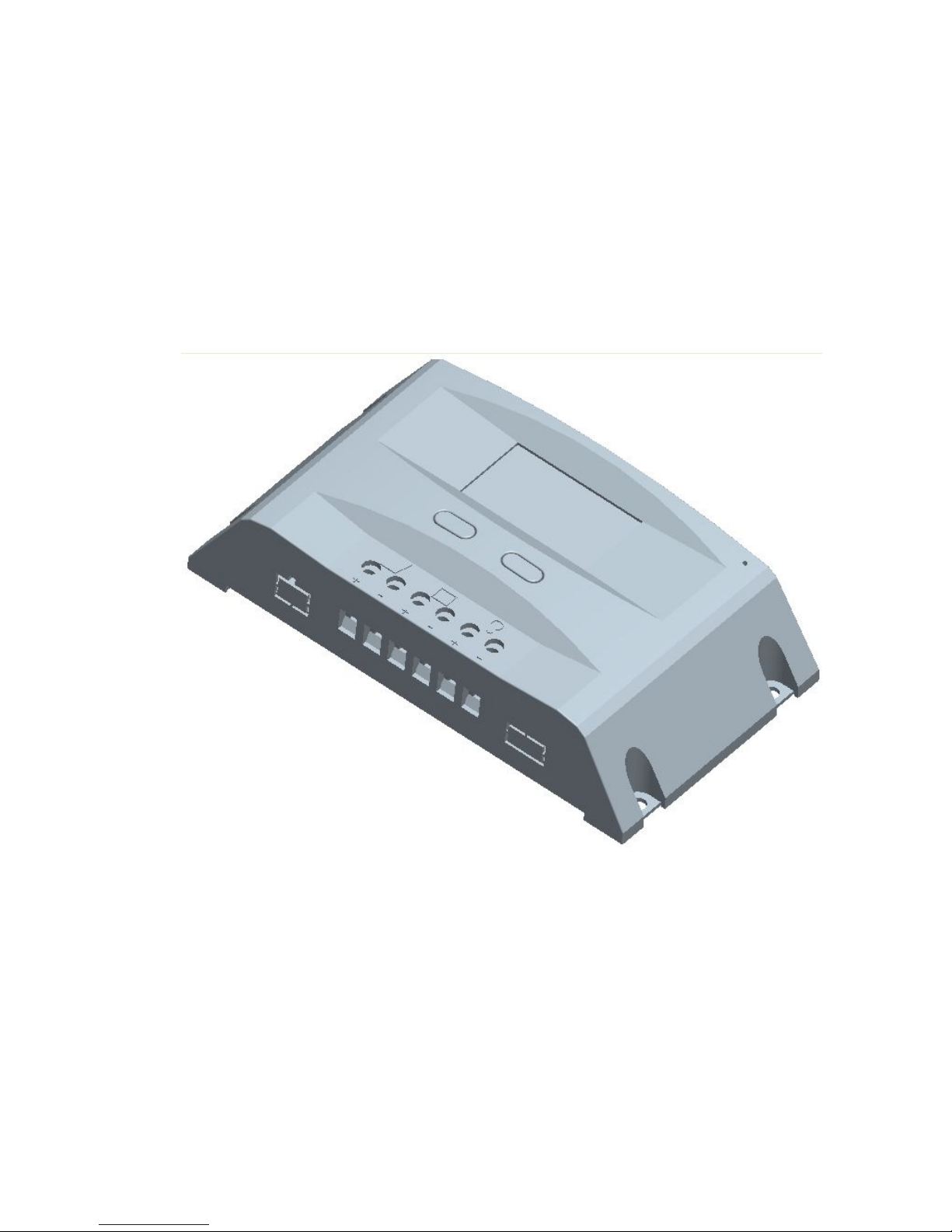
Controller Fixed
1) The controller should be installed well-ventilated place,
avoid direct sunlight, high temperature and do not
install in location where water can enter the controller.
2) Please select correct screw to fix the controller on the
wall or other platform. Screw M4 or M5, Screw cap
diameter less than 10mm.
3) Please reserve enough space between the wall and
controller, to allow for cooling and cable connection.
4) The mounting holes distance is 155.8mm*63mm,
diameter of the hole is 5mm.
 Loading...