

Page 1
LEVP-14W LED Series
INSTALLATION INSTRUCTIONS
Read instructions carefully before attempting to install fixture. Save these instructions.
WARNING: Disconnect power during installation and before servicing.
SAFETY: This fixture must be wired in accordance with the National Electric Code, and
applicable local codes and ordinances.
Proper grounding is required to insure personal safety.
A qualified electrician should perform all wiring.
Junction Box install method
Remove the Junction Box side cover screw.(Remo
the wire comes into the junction Box, install the UL listed conduit(1/2 trade size) and UL listed conduit
fitting(waterproof) to the junction Box, also the Junction Box just for one light fixture
Ceiling Mounting: “version A”
1. Attach the cast junction box to surface with screws (hardware by others).
2. Run conduit to junction box if application calls for it and pull supply leads into junction box
Note: Be sure to use Teflon tape to seal 1/2" NPT threads for Wet Location Environments!
3. Place gasket (from polybag) and make wiring connections from driver in LED Heatsink to supply leads as indicated
below on “Wiring Connections”.
4. Remove PC Lens with the gasket in place, attach LED Heatsink to junction box by using the two (2)
screws provided
the holes on
5. Replace PC Lens onto fixture by threading until tight (care must be given to not cross thread).
(Glass & Guard),
in polybag. Insert the screws through the holes on the inside of LED He
the “Adaptor Plate” mounted on the “Junction Box”and tighten.
(Glass & Guard),
Wall Mounting: “version B”
1. Attach the cast junction box to surface with screws (hardware by others).
2. Run conduit to junction box if application calls for it and pull supply leads into junction box with at least 6” lead showing.
Note: Be sure to
3. Connect the wires from the“Quick Disconnect”wiring harness provided in polybag, to the supply side wires from the
junction box as indicated below on “Wiring Connections”.
4. Next mount the “Wall Bracket”, first place gasket between J- box and Wall Bracket then insert the “Quick Disconnect
wiring harness through the inside of Wall Bracket, now attach Wall Bracket to junction box using
screws provided in
5. Next, using gasket provided in polybag, thread wiring through the gasket opening. Take the LED Heatsink and snap
together the two (2) “Quick Disconnects” one leading from the driver and the other coming out from the Wall Bracket.
6. Remove PC Lens
Insert
Bracket and
7. Replace PC Lens onto fixture by threading until tight (care must be given to not cross thread).
the
use Teflon tape to seal 1/
polybag and tighten securely.
(Glass & Guard),
screws through the holes on the inside of LED
tighten securely.
(Glass & Guard),
Form #D-1281 LDPI, Inc. 1-800-854-0021 Web:http://www.ldpi-inc.com Email: [email protected]
2" NPT threads for Wet Location Environments!
attach LED Heatsink to Wall Bracket using the two (2) screws provided in polybag.
ve only one screw of the Junction Box), depends which way
Heatsink. Next align the screws with the ho
with at least 6” lead showing.
atsink. Next align the screws with
the four (4) 3/4” long
les on the Wall
Page1
Page 2
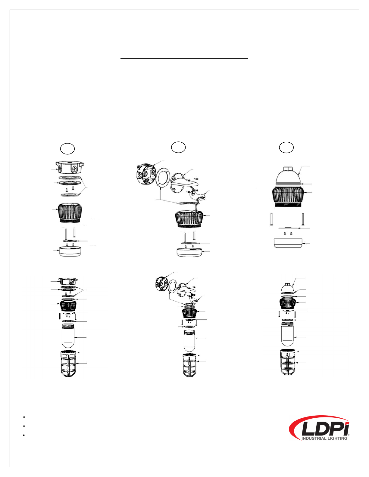
Junction Box
Adaptor Plate
LED Heatsink
Reflector
PC Lens
Gasket
Junction Box
Wall Bracket
Quick
LED Heatsink
Reflector
PC Lens
Gasket
PC Lens
Reflector
LED Heatsink
Gasket
Pendant Hub
A
C
INSTALLATION INSTRUCTIONS
Pendant Mounting:
1. Thread 1/2“ Pendant Hub onto conduit and pull supply wiring through conduit.
Note: Be sure to use Teflon tape to seal 1/2" NPT threads for Wet Location Environments!
2. Remove PC Lens using gasket provided in polybag, thread wiring through the gasket opening and make
wiring
connection as indicated below. Next attach LED Heatsink to Pendant Hub using the two (2) screws provided in
polybag. Insert the screws through the holes on the in
Hub and tighten securely
3. Replace PC Lens onto fixture by threading until tight (care must be given to not cross thread).
“version C”
(Glass & Guard),
(Glass & Guard),
ide of LED Heatsink and align the screws with the holes on the
s
Disconnect
Junction Box
Cover
Heatsink
Gasket
O-ring
Reflector
Gasket
Globe
Guard
Junction Box
Gasket
O-ring
Gasket
Wall Mount Arm
Disconnector
Heatsink
Reflector
Globe
Guard
Wiring Connections:
CAUTION: Check that supply voltage is compatible with fixture ballast.
Use approved connectors for all electrical connections.
Connect the black fixture wire to the black supply wire (line).
Connect the white fixture wire to the white supply w
Connect the green fixture wire to the junction box ground wire.
Form #D-1281 LDPI, Inc. 1-800-854-0021 Web:http://www.ldpi-inc.com Email: [email protected]
ire (neutral).
Pendant Hub
Gasket
O-ring
Heatsink
Reflector
Gasket
Globe
Guard
Page2
 Loading...